RU2534846C2 - Sewing system and device - Google Patents
Sewing system and device Download PDFInfo
- Publication number
- RU2534846C2 RU2534846C2 RU2012106297/14A RU2012106297A RU2534846C2 RU 2534846 C2 RU2534846 C2 RU 2534846C2 RU 2012106297/14 A RU2012106297/14 A RU 2012106297/14A RU 2012106297 A RU2012106297 A RU 2012106297A RU 2534846 C2 RU2534846 C2 RU 2534846C2
- Authority
- RU
- Russia
- Prior art keywords
- needle
- head
- capsule
- shaft
- longitudinal axis
- Prior art date
Links
Images

Classifications
-
- A—HUMAN NECESSITIES
- A61—MEDICAL OR VETERINARY SCIENCE; HYGIENE
- A61B—DIAGNOSIS; SURGERY; IDENTIFICATION
- A61B17/00—Surgical instruments, devices or methods, e.g. tourniquets
- A61B17/04—Surgical instruments, devices or methods, e.g. tourniquets for suturing wounds; Holders or packages for needles or suture materials
- A61B17/0482—Needle or suture guides
-
- A—HUMAN NECESSITIES
- A61—MEDICAL OR VETERINARY SCIENCE; HYGIENE
- A61B—DIAGNOSIS; SURGERY; IDENTIFICATION
- A61B17/00—Surgical instruments, devices or methods, e.g. tourniquets
- A61B17/04—Surgical instruments, devices or methods, e.g. tourniquets for suturing wounds; Holders or packages for needles or suture materials
- A61B17/0469—Suturing instruments for use in minimally invasive surgery, e.g. endoscopic surgery
-
- A—HUMAN NECESSITIES
- A61—MEDICAL OR VETERINARY SCIENCE; HYGIENE
- A61B—DIAGNOSIS; SURGERY; IDENTIFICATION
- A61B17/00—Surgical instruments, devices or methods, e.g. tourniquets
- A61B17/04—Surgical instruments, devices or methods, e.g. tourniquets for suturing wounds; Holders or packages for needles or suture materials
- A61B17/06—Needles ; Sutures; Needle-suture combinations; Holders or packages for needles or suture materials
- A61B17/06066—Needles, e.g. needle tip configurations
-
- A—HUMAN NECESSITIES
- A61—MEDICAL OR VETERINARY SCIENCE; HYGIENE
- A61B—DIAGNOSIS; SURGERY; IDENTIFICATION
- A61B17/00—Surgical instruments, devices or methods, e.g. tourniquets
- A61B17/04—Surgical instruments, devices or methods, e.g. tourniquets for suturing wounds; Holders or packages for needles or suture materials
- A61B17/06—Needles ; Sutures; Needle-suture combinations; Holders or packages for needles or suture materials
- A61B17/062—Needle manipulators
- A61B17/0625—Needle manipulators the needle being specially adapted to interact with the manipulator, e.g. being ridged to snap fit in a hole of the manipulator
-
- A—HUMAN NECESSITIES
- A61—MEDICAL OR VETERINARY SCIENCE; HYGIENE
- A61B—DIAGNOSIS; SURGERY; IDENTIFICATION
- A61B17/00—Surgical instruments, devices or methods, e.g. tourniquets
- A61B17/04—Surgical instruments, devices or methods, e.g. tourniquets for suturing wounds; Holders or packages for needles or suture materials
- A61B17/06—Needles ; Sutures; Needle-suture combinations; Holders or packages for needles or suture materials
- A61B17/06004—Means for attaching suture to needle
- A61B2017/06009—Means for attaching suture to needle having additional means for releasably clamping the suture to the needle, e.g. actuating rod slideable within the needle
-
- A—HUMAN NECESSITIES
- A61—MEDICAL OR VETERINARY SCIENCE; HYGIENE
- A61B—DIAGNOSIS; SURGERY; IDENTIFICATION
- A61B17/00—Surgical instruments, devices or methods, e.g. tourniquets
- A61B17/04—Surgical instruments, devices or methods, e.g. tourniquets for suturing wounds; Holders or packages for needles or suture materials
- A61B17/06—Needles ; Sutures; Needle-suture combinations; Holders or packages for needles or suture materials
- A61B17/06004—Means for attaching suture to needle
- A61B2017/06042—Means for attaching suture to needle located close to needle tip
-
- A—HUMAN NECESSITIES
- A61—MEDICAL OR VETERINARY SCIENCE; HYGIENE
- A61B—DIAGNOSIS; SURGERY; IDENTIFICATION
- A61B17/00—Surgical instruments, devices or methods, e.g. tourniquets
- A61B17/28—Surgical forceps
- A61B17/29—Forceps for use in minimally invasive surgery
- A61B17/2909—Handles
- A61B2017/2912—Handles transmission of forces to actuating rod or piston
- A61B2017/2919—Handles transmission of forces to actuating rod or piston details of linkages or pivot points
- A61B2017/292—Handles transmission of forces to actuating rod or piston details of linkages or pivot points connection of actuating rod to handle, e.g. ball end in recess
-
- A—HUMAN NECESSITIES
- A61—MEDICAL OR VETERINARY SCIENCE; HYGIENE
- A61B—DIAGNOSIS; SURGERY; IDENTIFICATION
- A61B17/00—Surgical instruments, devices or methods, e.g. tourniquets
- A61B17/28—Surgical forceps
- A61B17/29—Forceps for use in minimally invasive surgery
- A61B17/2909—Handles
- A61B2017/2912—Handles transmission of forces to actuating rod or piston
- A61B2017/2923—Toothed members, e.g. rack and pinion
-
- A—HUMAN NECESSITIES
- A61—MEDICAL OR VETERINARY SCIENCE; HYGIENE
- A61B—DIAGNOSIS; SURGERY; IDENTIFICATION
- A61B90/00—Instruments, implements or accessories specially adapted for surgery or diagnosis and not covered by any of the groups A61B1/00 - A61B50/00, e.g. for luxation treatment or for protecting wound edges
- A61B90/08—Accessories or related features not otherwise provided for
- A61B2090/0807—Indication means
- A61B2090/0811—Indication means for the position of a particular part of an instrument with respect to the rest of the instrument, e.g. position of the anvil of a stapling instrument
Landscapes
- Health & Medical Sciences (AREA)
- Life Sciences & Earth Sciences (AREA)
- Surgery (AREA)
- Heart & Thoracic Surgery (AREA)
- Engineering & Computer Science (AREA)
- Biomedical Technology (AREA)
- Nuclear Medicine, Radiotherapy & Molecular Imaging (AREA)
- Medical Informatics (AREA)
- Molecular Biology (AREA)
- Animal Behavior & Ethology (AREA)
- General Health & Medical Sciences (AREA)
- Public Health (AREA)
- Veterinary Medicine (AREA)
- Surgical Instruments (AREA)
- Portable Nailing Machines And Staplers (AREA)
Abstract
Description
Предпосылки создания изобретенияBACKGROUND OF THE INVENTION
Интракорпоральное сшивание ткани во время хирургических операций представляет трудности в том, что хирург должен работать сшивающими инструментами в пределах сравнительно небольшого надреза, образованного в теле пациента. В некоторых случаях хирург пальцами ощупывает необходимое место для размещения шва и не может видеть местоположение шва.Intracorporeal tissue stitching during surgery presents difficulties in that the surgeon has to work with stapling instruments within a relatively small incision formed in the patient’s body. In some cases, the surgeon feels with his fingers the necessary place to place the seam and cannot see the location of the seam.
Усовершенствованные сшивающие инструменты и усовершенствованные методы наложения швов были бы одобрены штатом хирургов.Advanced stapling tools and advanced suturing techniques would be approved by surgeons.
Сущность изобретенияSUMMARY OF THE INVENTION
Один аспект предоставляет сшивающее устройство, приспособленное накладывать шов в ткани. Сшивающее устройство включает рукоятку, имеющую привод, вал, соединенный с рукояткой, и головку, соединенную с валом. Головка включает ближнюю часть, содержащую иглу, которая может перемещаться через отверстие выхода иглы, и дальний конец, отделенный от ближней части горлышком, дальний конец определяет полость. Привод приспособлен выдвигать иглу из отверстия выхода иглы, образованного в ближней части головки, и через горлышко, чтобы зацеплять капсулу, расположенную в полости, образованной в дальнем конце головки, где капсула прикреплена к нити.One aspect provides a stapler adapted to suture tissue. The stapler includes a handle having a drive, a shaft connected to the handle, and a head connected to the shaft. The head includes a proximal portion containing a needle that can be moved through the needle exit hole, and a distal end separated from the proximal portion by the neck, the distal end defines a cavity. The drive is adapted to push the needle out of the needle exit hole formed in the proximal part of the head and through the neck to engage the capsule located in the cavity formed at the far end of the head, where the capsule is attached to the thread.
Краткое описание графических материаловA brief description of the graphic materials
Сопроводительные графические материалы подаются для обеспечения лучшего понимания вариантов осуществления и включаются в и представляют собой часть этого описания. Графические материалы иллюстрируют варианты осуществления и вместе с описанием служат для объяснения принципов вариантов осуществления. Другие варианты осуществления и множество задуманных преимуществ вариантов осуществления будут легко оценены, когда они станут более понятны благодаря обращению к последующему подробному описанию. Элементы графических материалов не обязательно представлены в масштабе друг относительно друга. Одинаковые номера позиций обозначают соответствующие подобные части.The accompanying graphic materials are provided to provide a better understanding of the embodiments and are included in and constitute a part of this description. The graphic materials illustrate embodiments and, together with the description, serve to explain the principles of the embodiments. Other embodiments and the many intended advantages of the embodiments will be readily appreciated when they become clearer by referring to the following detailed description. Elements of graphic materials are not necessarily scaled relative to each other. Identical reference numbers indicate corresponding similar parts.
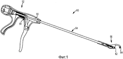
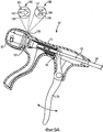
Фигура 1 представляет собой общий вид сбоку сшивающего инструмента согласно одному варианту осуществления.Figure 1 is a side elevational view of a stapling tool according to one embodiment.
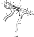
Фигура 2 представляет собой вид в поперечном сечении одного варианта осуществления рукоятки сшивающего инструмента, показанного на фигуре 1.Figure 2 is a cross-sectional view of one embodiment of the handle of the stapling tool shown in Figure 1.
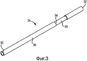
Фигура 3 представляет собой вид сбоку одного варианта осуществления вала сшивающего инструмента, показанного на фигуре 1.Figure 3 is a side view of one embodiment of the shaft of the stapling tool shown in Figure 1.
Фигура 4 представляет собой вид в поперечном сечении одного варианта осуществления толкающего стержня, расположенного в вале, показанном на фигуре 3.Figure 4 is a cross-sectional view of one embodiment of a push rod located in the shaft shown in Figure 3.
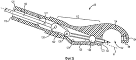
Фигура 5 представляет собой вид в поперечном сечении головки сшивающего инструмента, показанного на фигуре 1, включая подвижную иглу, согласно одному варианту осуществления.Figure 5 is a cross-sectional view of the head of the stapling tool shown in Figure 1, including a movable needle, according to one embodiment.
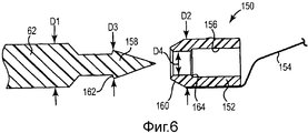
Фигура 6 представляет собой вид в поперечном сечении узла нити, включающего нить, прикрепленную к капсуле, которая приспособлена соединяться с иглой сшивающего инструмента, показанного на фигуре 1, согласно одному варианту осуществления.Figure 6 is a cross-sectional view of a yarn assembly including a thread attached to a capsule that is adapted to connect to the needle of the stapling tool shown in Figure 1, according to one embodiment.
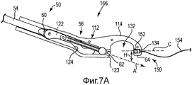
Фигура 7А представляет собой схематическое изображение в поперечном сечении головки сшивающего инструмента, показанной на фигуре 5, с иглой, втянутой в головку, согласно одному варианту осуществления.Figure 7A is a schematic cross-sectional view of the head of the stapling tool shown in Figure 5 with a needle pulled into the head, according to one embodiment.
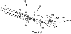
Фигура 7В представляет собой вид в поперечном сечении головки сшивающего инструмента, показанной на фигуре 5, с иглой, частично выступающей из отверстия выхода иглы в головке, согласно одному варианту осуществления.Figure 7B is a cross-sectional view of the head of the stapling tool shown in Figure 5, with a needle partially protruding from the needle exit hole in the head, according to one embodiment.
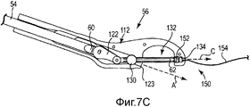
Фигура 7С представляет собой вид в поперечном сечении головки сшивающего инструмента, показанной на фигуре 5, с иглой, переброшенной в дальний конец головки и скрепленной с узлом нити, показанным на фигуре 6, согласно одному варианту осуществления.Figure 7C is a cross-sectional view of the head of the stapling tool shown in Figure 5 with a needle thrown to the far end of the head and fastened to the thread assembly shown in Figure 6 according to one embodiment.
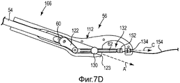
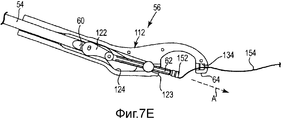
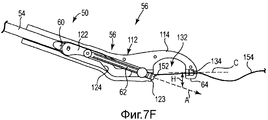
Фигуры 7D-7F представляют собой схематические изображения в поперечном сечении иглы сшивающего инструмента, показанного на фигуре 1, сцепленной с узлом нити и отводящей капсулу узла нити обратно в ближайшую крайнюю часть головки, согласно одному варианту осуществления изобретения.Figures 7D-7F are schematic cross-sectional views of the needle of the stapling tool shown in Figure 1, coupled to the thread assembly and leading the capsule of the thread assembly back to the closest end of the head, according to one embodiment of the invention.
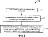
Фигура 8 представляет собой блок-схему способа сшивания ткани согласно одному варианту осуществления.Figure 8 is a flowchart of a method for stitching tissue according to one embodiment.
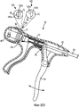
Фигура 9А представляет собой вид в поперечном сечении еще одного варианта осуществления рукоятки, приспособленной для использования со сшивающим инструментом, показанным на фигуре 1.Figure 9A is a cross-sectional view of yet another embodiment of a handle adapted for use with the stapling tool shown in Figure 1.
Фигура 9В представляет собой вид в поперечном сечении еще одного варианта осуществления рукоятки, приспособленной для использования со сшивающим инструментом, показанным на фигуре 1.Figure 9B is a cross-sectional view of yet another embodiment of a handle adapted for use with the stapling tool shown in Figure 1.
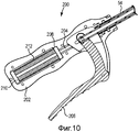
Фигура 10 представляет собой вид в поперечном сечении еще одного варианта осуществления рукоятки, приспособленной для использования со сшивающим инструментом, показанным на фигуре 1.Figure 10 is a cross-sectional view of yet another embodiment of a handle adapted for use with the stapling tool shown in Figure 1.
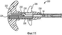
Фигура 11 представляет собой вид в поперечном сечении еще одного варианта осуществления рукоятки, приспособленной для использования со сшивающим инструментом, показанным на фигуре 1.Figure 11 is a cross-sectional view of yet another embodiment of a handle adapted for use with the stapling tool shown in Figure 1.
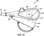
Фигура 12 представляет собой вид в поперечном сечении еще одного варианта осуществления рукоятки, приспособленной для использования со сшивающим инструментом, показанным на фигуре 1.Figure 12 is a cross-sectional view of yet another embodiment of a handle adapted for use with the stapling tool shown in Figure 1.
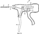
Фигура 13 представляет собой вид в поперечном сечении еще одного варианта осуществления рукоятки, приспособленной для использования со сшивающим инструментом, показанным на фигуре 1.Figure 13 is a cross-sectional view of yet another embodiment of a handle adapted for use with the stapling tool shown in Figure 1.
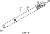
Фигура 14 представляет собой общий вид еще одного варианта осуществления вала, приспособленного для использования со сшивающим инструментом, показанным на фигуре 1.Figure 14 is a General view of another embodiment of a shaft adapted for use with the stapling tool shown in Figure 1.
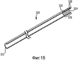
Фигура 15 представляет собой вид в поперечном сечении еще одного варианта осуществления вала, приспособленного для использования со сшивающим инструментом, показанным на фигуре 1.Figure 15 is a cross-sectional view of yet another embodiment of a shaft adapted for use with the stapling tool shown in Figure 1.
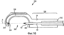
Фигура 16 представляет собой вид в поперечном сечении еще одного варианта осуществления головки, приспособленной для использования со сшивающим инструментом, показанным на фигуре 1.Figure 16 is a cross-sectional view of yet another embodiment of a head adapted for use with the stapling tool shown in Figure 1.
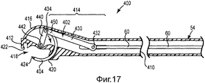
Фигура 17 представляет собой вид в поперечном сечении еще одного варианта осуществления головки, приспособленной для использования со сшивающим инструментом, показанным на фигуре 1.Figure 17 is a cross-sectional view of yet another embodiment of a head adapted for use with the stapling tool shown in Figure 1.
Подробное описание изобретенияDETAILED DESCRIPTION OF THE INVENTION
В следующем подробном описании производятся ссылки на сопутствующие графические материалы, которые образуют его часть, и на которых при помощи примеров показываются характерные варианты осуществления, в которых изобретение может быть осуществлено на практике. В этом отношении термины, обозначающие направленность, такие как «верх», «низ», «перед», «зад», «ведущий», «замыкающий» и т.п. используются в отношении направленности описываемой фигуры (фигур). Поскольку компоненты вариантов осуществления могут размещаться при помощи ряда различных положений, термины направленности используются с иллюстративной целью и ни в коем случае не являются ограничивающими. Следует понимать, что могут использоваться другие варианты осуществления, а конструкционные или логические изменения могут производиться без отступления от объема данного изобретения. Следующее подробное описание, таким образом, не следует воспринимать в ограничивающем смысле, а объем настоящего изобретения определяется прилагаемой формулой изобретения.In the following detailed description, reference is made to the accompanying graphic materials, which form a part of it, and on which, by way of examples, characteristic embodiments are shown in which the invention can be practiced. In this regard, terms indicating directionality, such as “top”, “bottom”, “front”, “backside”, “leading”, “closing”, etc. are used in relation to the direction of the described figure (s). Since the components of the embodiments may be placed using a number of different provisions, the directivity terms are used for illustrative purposes and are by no means limiting. It should be understood that other embodiments may be used, and structural or logical changes may be made without departing from the scope of the present invention. The following detailed description, therefore, should not be taken in a limiting sense, and the scope of the present invention is defined by the attached claims.
Нужно понимать, что свойства разнообразных иллюстративных вариантов осуществления, описанных здесь, могут сочетаться друг с другом, если только другое не указано отдельно.It should be understood that the properties of the various illustrative embodiments described herein may be combined with each other, unless otherwise indicated separately.
Ткань включает мягкую ткань, которая включает кожную ткань, подкожную ткань, связки, сухожилия или мембраны. Так, как понимается в этом описании, термин «ткань» не включает кость.Tissue includes soft tissue, which includes skin tissue, subcutaneous tissue, ligaments, tendons, or membranes. So, as understood in this description, the term "tissue" does not include bone.
В этом описании «сдвиг» обозначает перемещение объекта от первой оси к другой оси, которая отлична от первой оси. Например, в одном варианте осуществления сшивающее устройство включает иглу, которая перемещается в первом направлении (например, вдоль продольной оси) и затем перемещается во втором направлении, отличном от первого направления (то есть, от продольной оси); таким образом, игла сдвигается от продольной оси, когда вводится в действие из устройства.In this description, “shift” refers to the movement of an object from a first axis to another axis that is different from the first axis. For example, in one embodiment, the stapler includes a needle that moves in a first direction (eg, along a longitudinal axis) and then moves in a second direction other than the first direction (i.e., from a longitudinal axis); thus, the needle moves away from the longitudinal axis when brought into use from the device.
В этом описании «крайний» обозначает «самый крайний», а «часть конца» означает ту часть, которая находится рядом с концом и протягивается из конца. Например, ближний конец - это тот крайний участок ручного инструмента, который является ближайшим к пользователю, а часть ближнего конца - это та часть (например, рукоятка ручного инструмента), которая находится рядом с и вытягивается наружу из ближнего конца.In this description, “extreme” means “the most extreme”, and “part of the end” means that part which is near the end and extends from the end. For example, the proximal end is the extreme portion of the hand tool that is closest to the user, and the proximal end is the part (for example, the handle of the hand tool) that is near and extends outward from the proximal end.
Варианты осуществления предоставляют сшивающее устройство, имеющее иглу, расположенную в части ближнего конца головки устройства, где игла вводится в действие продольно из части ближнего конца головки через массу ткани и затем захватывает узел нити. Игла втягивается после зацепления узла нити и тянет узел нити через игольное отверстие (например, повреждение), образованное в ткани. Таким образом, сшивающее устройство проходит сквозь ткань, захватывает узел нити и втягивает узел нити через ткань, чтобы завершить «стежок» в ткани.Embodiments provide a stapler having a needle located in a portion of the proximal end of the head of the device, where the needle is inserted longitudinally from a portion of the proximal end of the head through a mass of fabric and then grips the thread assembly. The needle retracts after the thread assembly is engaged and pulls the thread assembly through the needle hole (eg, damage) formed in the fabric. Thus, the stapler passes through the fabric, grabs the thread unit and draws the thread unit through the fabric to complete the “stitch” in the fabric.
В одном варианте осуществления предоставляется шовная система, которая включает узел нити и капсулу, которая прикрепляется к отрезку хирургической нити. Варианты осуществления сшивающего устройства включают головку, имеющую дальний конец, который определяет полость, имеющую такой размер, чтобы удерживать капсулу. Игла размещается в части ближнего конца головки и может перемещаться из отверстия выхода иглы в полость, образованную в дальнем конце головки. Игла приспособлена зацеплять капсулу узла нити.In one embodiment, a suture system is provided that includes a suture unit and a capsule that is attached to a piece of surgical suture. Embodiments of the crosslinking device include a head having a distal end that defines a cavity having such a size as to hold the capsule. The needle is placed in the part of the proximal end of the head and can move from the outlet of the needle to the cavity formed at the far end of the head. The needle is adapted to engage the thread unit capsule.
Варианты осуществления предоставляют сшивающее устройство, имеющее линейную головку, которая приспособлена выбрасывать иглу в продольном направлении из отверстия выхода иглы, через пространство горлышка, и в полость, образованную в дальнем конце линейной головки.Embodiments provide a stapler having a linear head that is adapted to eject the needle in the longitudinal direction from the needle exit hole, through the neck space, and into a cavity formed at the far end of the linear head.
Варианты осуществления предоставляют сшивающее устройство, имеющее головку с радиально смещенным дальним концом, где головка приспособлена выбрасывать иглу вдоль в первом направлении через отверстие выхода иглы, передвигать иглу с продольной оси во втором направлении, отличном от первого направления, и в полость, образованную в радиально смещенном дальнем конце.Embodiments provide a stapler having a head with a radially offset distal end, where the head is adapted to eject the needle lengthwise in the first direction through the needle exit hole, move the needle from the longitudinal axis in a second direction different from the first direction, and into the cavity formed in the radially offset far end.
Варианты осуществления предоставляют сшивающее устройство, приспособленное выбрасывать иглу в сцепление трения с капсулой, тянущей отрезок нити. Сшивающее устройство размещает стежок в ткани каждый раз, когда капсула возвращается, и хирург, увидев вернувшуюся капсулу, получает визуальную положительную обратную связь об успешном наложении шва.Embodiments provide a stapler adapted to eject a needle into friction engagement with a capsule pulling a length of thread. A stapler places a stitch in the tissue each time the capsule returns, and the surgeon, upon seeing the capsule return, receives visual positive feedback about successful stitching.
Фигура 1 представляет собой общий вид сбоку сшивающего устройства 50, приспособленного размещать шов в ткани, согласно одному варианту осуществления. Сшивающее устройство 50 включает рукоятку 52, вал 54, соединенный с рукояткой 52, и головку 56, соединенную с валом 54. Рукоятка 52, таким образом, определяет ближний конец сшивающего устройства 50 и является ближайшей к пользователю сшивающего устройства 50.Figure 1 is a side elevational view of a
В одном варианте осуществления рукоятка 52 включает привод 58, сообщающийся со стержнем 60, который располагается в вале 54. Когда привод 58 активируется, стержень 60 перемещается через вал 54, чтобы протягивать иглу 62, хранящуюся в части ближнего конца головки 56, наружу в направлении оси через ткань и по направлению к дальнему концу 64 головки 56. Таким образом, игла 62 перемещается от пользователя (который держит рукоятку 52 за ближний конец сшивающего устройства 50) по направлению к дальнему концу 64 сшивающего устройства 50.In one embodiment, the
В одном варианте осуществления капсула (не показана) удерживается в дальнем конце 64, а игла 62 имеет такую форму, чтобы трением сцепляться и сопрягаться с капсулой, извлекать капсулу из дальнего конца 64, и втягивать капсулу в часть ближнего конца головки 56. Таким образом, нить, тянущаяся за капсулой, «пробрасывается» через ткань. Варианты осуществления, описанные ниже, включают направляющий штифт, расположенный в головке 56, который приспособлен отцеплять капсулу от иглы 62.In one embodiment, a capsule (not shown) is held at the
Сшивающее устройство 50 подходит для интракорпорального наложения швов на ткань во время хирургических операций, и в одном варианте осуществления предоставляется как стерильный одноразовый хирургический инструмент, который выбрасывают после хирургической процедуры. С этой целью компоненты устройства 50 выбираются так, чтобы подходить для газовой, паровой или радиационной стерилизации.A
Фигура 2 представляет собой вид в поперечном сечении одного варианта осуществления рукоятки 52. В одном варианте осуществления рукоятка 52 находится на линии с главной продольной осью А и включает корпус 70, тянущийся между дальним концом 72 и ближним концом 74, скобу 76 для большого пальца, выходящую вбок из корпуса 70, курок 78, разнесенный со скобой 76 для большого пальца, и ручку 80, соединенную с ближним концом 74.Figure 2 is a cross-sectional view of one embodiment of the
В одном варианте осуществления корпус 70 производится из пластмассы, например, при помощи литья под давлением. Подходящие пластмассы для производства корпуса 70, скобы 76 и ручки 80 включают, в качестве примеров, поликарбонат, полиэтилен, акрилонитрил-бутадиен-стирол, акриловую смолу или нейлон. В одном варианте осуществления скоба 76 целостно отлита с корпусом 70 типа ракушки, и эти две детали соединяются вместе, чтобы удерживать курок 78 и рукоятку 80. Курок 78 создается с существенной прочностью, чтобы выдерживать изгиб при приведение в действие рукой человека. Подходящие материалы для создания курка 78 включают металл, такой как алюминий, или пластмассы, такие как полиэфиримид или поли-эфир-эфир-кетон.In one embodiment, the
Вал 54 соединяется с дальним концом 72 корпуса70, а стержень 60 располагается в вале 54 и соединяется с курком 78. В одном варианте осуществления привод 58 включает курок 78, скрепленный со стержнем 60, и пружину 82, расположенную в толкателе 84 пружины и смещенную к внутреннему ребру 86. Курок 78 может перемещаться в направлении к скобе 76 для большого пальца, чтобы продольно передвигать стержень 60 в периферическом направлении в вале 54, который сжимает пружину 82. Когда курок 78 освобождается, пружина 82 вытягивается, чтобы толкать толкатель 84 пружины проксимально, что отводит или возвращает стержень 60 в направлении ближнего конца 74. Курок разнесен со скобой 76 для большого пальца на расстояние примерно 4-12 см, чтобы дать возможность пальцам пользователя удобно приводить курок 78 в действие. Курок 78 размещается под углом В относительно продольной оси А корпуса 70, и в иллюстративном варианте осуществления угол В находится в диапазоне от 70 до 110 градусов, так что курок 78 примерно перпендикулярен продольной оси А.The
Привод 58 приспособлен передвигать стержень 60 вперед в периферическом направлении и обратно в направлении к центру в вале 54. В одном варианте осуществления желательно передвигать стержень 60 назад на дополнительное расстояние, чтобы отцеплять узел нити, описанный ниже, от иглы 62 (фигура 1). Чтобы облегчить это, стержень 60 включает втулку (не показана), которая сообщается через толкатель 84 пружины и захватывается в окне 88. Когда ручка 80 поворачивается, поворачивается толкатель 84 пружины, и втулка, скрепленная со стержнем 60, втягивается назад в периферическом направлении благодаря углу окна 88, которое втягивает стержень 60 на дополнительное расстояние в корпус 70. Например, в одном варианте осуществления ручка 80 устроена так, что поворот ручки 80 на 180 градусов по часовой стрелке относительно конца 74 вытягивает стержень 60 в корпус 70 на дополнительное расстояние около 2 мм. Хотя ручка 80 приспособлена втягивать стержень 60 дальше в корпус 70 посредством вращательного движения, для втягивания стержня 60 назад с определенным шагом также приемлемыми являются и другие механизмы, такие как рычаги или тяговые брусья.The
Фигура 3 представляет собой вид сбоку вала 54. Один применимый вариант осуществления вала 54 включает в значительной мере кольцеобразную жесткую алюминиевую трубку, протягивающуюся между ближним концом, который скрепляется с рукояткой 52 (фигура 1), и дальним концом, который скрепляется с головкой 56. Другие в значительной мере жесткие материалы, такие как нержавеющая сталь, также являются подходящим выбором для изготовления вала 54. Другой вариант осуществления вала 54 включает часть дальнего конца, связанную с дальним концом 92, которая является гибкой и приспособлена изгибаться в сторону относительно первой части 96, чтобы позволять хирургу избирательно направлять головку 56 в желаемое положение.Figure 3 is a side view of the
Например, один вариант осуществления вала 54 включает ближний конец 90, который скрепляется с рукояткой 52 (фигура 1), дальний конец 92, который скрепляется с головкой 56 (фигура 1), и сгиб 94 или сварной шов 94 соединяет первую часть 96 со второй частью 98. В одном варианте осуществления вал 54 образован в виде тонкостенной трубки с первой частью 96, образованной из первого материала, а вторая часть 98, образуется из другого второго материала. В иллюстративном варианте осуществления первая часть 96 выполнена из алюминия ряда 6000, а вторая часть 98 выполнена из алюминия ряда 3000, где эти две металлические части 96, 98 соединяются вместе сгибом/сварным швом 94. Алюминий ряда 6000 выбирается так, чтобы иметь модуль сдвига достаточной величины, чтобы не давать пользователю согнуть первую часть 96 при работе с инструментом 50. Например, в одном варианте осуществления модуль сдвига первой части 96 примерно равен 30 ГН/м2. Алюминий ряда 3000 выбирается так, чтобы иметь модуль сдвига достаточной величины, чтобы позволять пользователю сгибать вторую часть 98 своими руками, что дает возможность пользователю определять форму и направлять вторую часть 98 (которая скрепляется с головкой 56) при контроле и направлении размещения швов головкой 56. Например, в одном варианте осуществления модуль сдвига второй части 98 примерно равен 10 ГН/м2. В другом примере, в одном варианте осуществления предел текучести первой части 96 примерно равен 30 ГН/м2. Алюминий ряда 3000 выбирается так, чтобы иметь предел текучести достаточной величины, чтобы позволять пользователю сгибать вторую часть 98 своими руками, что дает возможность пользователю определять форму и направлять вторую часть 98 (которая скрепляется с головкой 56) при контроле и направлении размещения швов головкой 56. Например, в одном варианте осуществления предел текучести второй части 98 примерно равен 10 ГН/м2.For example, one embodiment of the
В одном примере подходящими длинами для частей 96, 98 являются, для первой части 96 - иметь длину от 4 до 24 см, для второй части 98 - иметь длину от 1 до 10 см. Другие длины для частей 96, 98 также допустимы. В одном варианте осуществления сгиб/сварной шов 94 представлен в виде металлического сгиба по краю, скрепляющего первую часть 96 со второй частью 98.In one example, suitable lengths for
Фигура 4 представляет собой вид в поперечном сечении стержня 60, расположенного в вале 54. Стержень 60, как правило, включает ближний конец 100, который соединяется с толкателем 84 (фигура 2), и дальний конец 102, который сообщается с иглой 62. В одном варианте осуществления ближний конец 100 стержня 60 является жестким, а остальная часть стержня 60 образуется так, чтобы включать спиральную пружину, где многочисленные витки 104 поджимают так, что стержень 60 имеет достаточную прочность на сжатие (например, вдоль своей главной оси), чтобы давать возможность стержню 60 приводить в действие иглу 62, и обеспечивается гибкостью, чтобы сгибаться в сторону. В одном варианте осуществления вся длина стержня 60 образуется из спиральной пружины из нержавеющей стали и заключается в вале 54 (фигура 3), чтобы обеспечивать стержень 60 прочностью на сжатие, способной противодействовать изгибу под осевыми нагрузками, а витки 104 приспособлены позволять головке 56 (фигура 1) сгибаться и передвигаться в сторону при приложении радиальной нагрузки. Таким образом, пользователь инструмента 50 (фигура 1) может прилагать усилие к валу 54 и стержню 60, чтобы прикладывать направленную вперед силу, в то же время имея в своем распоряжении гибкость и контроль над конфигурацией того, где головка 56 ориентируется относительно рукоятки 52.Figure 4 is a cross-sectional view of the
В одном варианте осуществления стержень 60 образуется из спиральной пружины из нержавеющей стали и включает полиэтиленовый кожух, как один пример, расположенный вокруг спиральной пружины.In one embodiment, the
В одном варианте осуществления только ведущая часть 106 стержня 60 образуется из спиральных пружин 104, где ведущая часть 106 соответствует гибкой второй части 98 вала 54, так что стержень 60 обеспечивается в значительной мере той же поперечной гибкостью, что вал 54.In one embodiment, only the driving
В одном варианте осуществления стержень 60 образуется из алюминия и сконфигурирован иметь такую же гибкость, как вал 54.In one embodiment, the
Фигура 5 представляет собой вид головки 56 в поперечном сечении. В одном варианте осуществления головка 56 образуется из двух сочетающихся скрепляющихся компонентов, и изображение фигуры 5 дается с одной снятой половиной скрепляющейся конструкции, так что видны внутренние свойства головки 56. Головка 56 отливается из пластмассы, например, из полиэфиримидной пластмассы, продаваемой под торговой маркой Ultem, или из стеклонаполненных полиэстеримидных пластмасс, также продаваемых под торговой маркой Ultem.Figure 5 is a cross-sectional view of a
В одном варианте осуществления головка 56 включает ближний конец 110, противоположный дальнему концу 64, часть 112 ближнего конца, протягивающуюся из ближнего конца 110, и шейку 114, которая протягивается между частью 112 ближнего конца и дальним концом 64. Головка 56 крепится к валу 54 и в одном варианте осуществления включает отверстие 120, имеющее такой размер, чтобы принимать вал 54, так что стержень 60 протягивается в часть 112 ближнего конца и соединяется с тягой 122, которая скрепляется с иглой 62. В одном варианте осуществления дальний конец 64 не выровнен с, а скорее смещен радиально от продольной оси А, чтобы более удобно для хирурга располагать вал 54 для манипулирования, когда головка 56 сцеплена с тканью.In one embodiment,
В одном варианте осуществления шплинтуемый штифт 121 соединяет ближний крайний конец тяги 122 со стержнем 60, а дальний конец тяги 122 соединяется с иглой 62. Движение стержня 60 перемещает тягу 122, которая выдвигает иглу 62 в и из отверстия 123 выхода иглы, образованного в части 112 ближнего конца. В одном варианте осуществления дорожка 124, которая образована на внутренней поверхности 125 части 112 ближнего конца головки 56, и тяга 122 приспособлена передвигаться и вращаться в дорожке 124, чтобы перемещать иглу 62 вдоль оси А и отклонять иглу вверх/вниз относительно оси А. Например, в одном варианте осуществления тяга 122 включает первый шплинт 126, который соединяется со скобой 121, и второй шплинт 128, который соединяется с иглой 62. Осевое движение стержня 60 переводится в осевое движение тяги 122 и иглы 62, и тяга 122 вращается вокруг шплинтов 126, 128, чтобы сдвинуть путь иглы 62 с оси А.In one embodiment, the
Тяга, таким образом, приспособлена перемещаться в дорожке 124, чтобы двигать иглу 62 внутрь/вовне относительно отверстия 123 выхода иглы, и вращаться относительно шплинтов 126, 128, чтобы направлять движение иглы 62 вниз/вверх относительно продольной оси А. В одном варианте осуществления часть 112 ближнего конца включает направляющий штифт 130, который определяет канал такого размера, чтобы принимать иглу 62. Игла 62 способна скользить через канал, образованный в направляющем штифте 130, и направляющий штифт 130 может вращаться, чтобы позволять игле 62 отклоняться от продольной оси А, когда игла 62 перемещается в осевом направлении, например, когда игла 62 перемещается в сцепление с дальним концом 64.The rod is thus adapted to move in
Шейка 114 протягивается между частью 112 ближнего конца и дальним концом 64 и определяет горлышко 132. Игла 62 может передвигаться от части 112 ближнего конца, из отверстия 123 выхода иглы, через горлышко 132 и в полость 134, образованную в дальнем конце 64. В одном варианте осуществления и дальний конец 64, и полость 134 радиально разнесены с продольной осью А, и направляющий штифт 130 вращается, чтобы дать возможность игле 62 выдвигаться из отверстия 123 выхода иглы, наклоняться вверх и в полость 134. В одном варианте осуществления верхняя сторона шейки 114 определяет свободный открытый желоб, приспособленный принимать и направлять нить, которая вытягивается из капсулы 152 (фигура 6), захваченной в полости 134, обратно к рукоятке 52 (фигура 1).The
Как описано ниже, полость 134 приспособлена удерживать капсулу, скрепленную с нитью (см. фигуру 7), а игла 62 приспособлена проходить ткань и входить в полость 134, скрепляться с капсулой и тянуть капсулу через ткань в отверстие 123 выхода иглы, чтобы «пробрасывать» нить через горлышко 132. Как описано ниже, варианты осуществления головки 56 включают механизмы, приспособленные линейно направлять иглу 62 из отверстия 123 выхода иглы через горлышко 132 и в полость 134 для сцепления с капсулой. Другие варианты осуществления головки 56 включают механизмы, приспособленные сдвигать иглу 62 (например, наклонять иглу 62 вверх относительно оси А из отверстия 123 выхода иглы и в полость 134 для сцепления с капсулой).As described below, the
Фигура 6 представляет собой вид сбоку иглы 62, выровненной для сцепления с узлом 150 нити согласно одному варианту осуществления. Игла 62 предпочтительно изготавливается из металла, такого как нержавеющая сталь или сплав с памятью формы, например, такой как NITINOL (никель-титановый сплав лаборатории вооружений ВМС США). Узел 150 нити включает капсулу 152 и нить 154, вытягивающуюся из капсулы 152. В одном варианте осуществления капсула 152 отливается под давлением из пластмассы, чтобы полностью захватывать нить 154. Пригодные пластмассы для изготовления капсулы 152 включают, например, полипропилен, полисульфон, уретан или полиэфирамид. Нить 154 включает, например, моноволоконную нить, плетеную нить, нить с покрытием или подобные.6 is a side view of a
Капсула 152 имеет такой размер, чтобы располагаться и удерживаться в полости 134 (фигура 5) и определяет выемку 156, приспособленную принимать ведущий конец 158 иглы 62. В одном варианте осуществления игла 62 имеет размер, способствующий надежному сцеплению с капсулой 152, а ведущий конец 158 имеет форму конического острия с выступом 162, который имеет такой размер, чтобы вдавливаться в сцепление с кромкой 164 выемки 156. Например, кромка 164, которая имеет такой размер и форму, чтобы трением сцепляться (например, защелкиваться) «фиксирующимся» образом с выступом 162 иглы 62, когда игла 62 вводится в выемку 156. Капсула 152 приспособлена открепляться от иглы 62 при помощи направляющего штифта 130 (фигура 5) после того, как игла 62 затягивает капсулу 152 обратно в ближнем направлении в головку 56.The
Коническое острие иглы 62 приспособлено образовывать канал при продвижении через ткань, а капсула 152 имеет такой размер, чтобы протягиваться через канал в ткани, созданный иглой 62. В одном варианте осуществления ведущий конец 160 капсулы 152 скошен, а игла 62 приспособлена протягивать скошенный (или усеченный) конец 160 капсулы 152 первым через ткань. В одном варианте осуществления ведущий конец 160 капсулы 152 является тупым концом, похожим на тот, что показан для замыкающего конца капсулы 152, а игла 62 приспособлена протягивать тупой конец 160 капсулы 152 тупым концом вперед через ткань.The conical tip of the
Например, в одном варианте осуществления игла 62 имеет первый диаметр D1, а капсула 152 имеет диаметр D2, где диаметр D1 равен или превосходит диаметр D2. Таким образом, капсула 152 имеет такой размер, чтобы следовать за иглой 62 и протягиваться через канал, созданный в ткани иглой 62.For example, in one embodiment, the
Ведущий конец 158 иглы 62 имеет такой размер, чтобы сцепляться трением с выемкой 156, образованной в капсуле 152. Например, в одном варианте осуществления ведущий конец 158 имеет диаметр D3, который немного больше, чем диаметр D4, образованный в отверстии выемки 156. Таким образом, когда ведущий конец 158 иглы 62 вставляется в выемку 156, ведущий конец 158 вводится с усилием и устанавливается в и захватывает капсулу 152.The
Фигуры 7A-7F представляют собой схематические изображения в поперечном сечении, демонстрирующие сшивающую систему 166, включающую сшивающий инструмент 50 и узел 150 нити, используемую для проталкивания иглы 62 из ближнего положения в дальнее положение головки 56, сцепления иглы 62 с капсулой 152/нитью 154 узла 150, и протягивания капсулы 152/нити 154 через ткань.Figures 7A-7F are schematic cross-sectional views illustrating a
Фигура 7А представляет собой схематическое изображение в поперечном сечении устройства 166 с иглой 62, полностью втянутой в отверстие 123 выхода иглы части 112 ближнего конца головки 56. Капсула 152 усаживается в полости 134 с нитью 154, тянущейся позади головки 56. В одном варианте осуществления рекомендуется, чтобы хирург направлял замыкающий конец нити 154 через дальний конец 64 головки 56 и обратно по направлению к ближнему концу вала 54 для облегчения управления узлом 150 нити во время процедуры. Например, один вариант осуществления дальнего конца 64 включает прорезь, приспособленную позволять нити 154 проходить через дальний конец 64, чтобы способствовать заведению капсулы 152 в полость 134. В одном варианте осуществления стержень 60 и игла 62 выровнены на оси А, когда игла 62 втянута в часть 112 ближнего конца, как показано, а капсула 152 выровнена по оси С, которая не совпадает с осью А.Figure 7A is a cross-sectional diagram of a
Фигура 7В представляет собой схематическое изображение в поперечном сечении устройства 166 с иглой 62, частично выходящей из отверстия 123 выхода иглы после приведения в действие привода 58 (фигура 1). Движущийся по оси в периферическом направлении стержень 60 выдвигает иглу 62 из отверстия 123 выхода иглы в первом направлении вдоль оси А. В одном варианте осуществления дальний конец 64 радиально разнесен с продольной осью А на расстояние H, так что первое направление направлено вдоль оси А, что приводит к тому, что траектория иглы 62 смещается от полости 134 на расстояние H. Часть иглы 62 вытягивается из отверстия 123 выхода иглы до некоторой степени через горлышко 132, а направляющий штифт 130 приспособлен вращаться против часовой стрелки, чтобы обеспечивать движение тяги 122 в дорожке 124, чтобы сдвигать ведущий конец 158 иглы 62 с первого направления, направленного вдоль оси А, на второе направление, совмещенное с осью С, которая протягивается через полость 134.Figure 7B is a schematic cross-sectional view of a
Фигура 7С представляет собой схематическое изображение в поперечном сечении устройства 166, включающего иглу 62, сдвинутую с продольной оси А тягой 122 и штифтом 130, перемещенную во втором направлении вдоль оси С стержнем 60, и сцепленную с капсулой 152. Направляющий штифт 130 вращается против часовой стрелки, чтобы обеспечить перемещение тяги 122 в дорожке 124, чтобы сдвинуть направление иглы 62 от совмещения с осью А и в совмещение с осью С. Дополнительное движение вперед стержня 60 также направит иглу 62 через горлышко 132 и в сцепление с капсулой 152. Как описано ниже, игла 62 может двигаться назад вдоль траекторий, совпадающих с осью С и осью А, чтобы втягивать иглу 62 и капсулу 152 в отверстие 123 выхода иглы.Figure 7C is a schematic cross-sectional view of a
Фигуры 7D-7F представляют собой схематические изображения в поперечном сечении иглы 62, сцепленной с капсулой 152 и готовой для втягивания и установки капсулы 152 обратно в части 112 ближнего конца головки 56.Figures 7D-7F are schematic cross-sectional views of a
Фигура 7D представляет собой схематическое изображение иглы 62, сцепленной с капсулой 152 и оттянутой вдоль оси С на короткое расстояние, так что капсула 152 извлечена из полости 134 и в горлышко 132. Дополнительное втягивание назад стержня 60 приведет к вращению штифта 130 по часовой стрелке, чтобы обеспечить движение тяги 122 в дорожке 124, чтобы сместить иглу 62 с оси С и совместить с осью А. Нить 154 тянется за капсулой 152 и из задней стороны полости 134.Figure 7D is a schematic representation of a
Фигура 7E представляет собой схематическое изображение иглы 62, частично втянутой в часть 112 ближнего конца головки 56. Тяга 122 переместилась в центр дорожки 124, так что игла 62 и капсула 152 сместились вниз в совмещение с осью А. Втягивание стержня 60 в осевом направлении в вал 54 тянет иглу 62 и капсулу 152 в отверстие 123 выхода иглы.Figure 7E is a schematic illustration of a
Фигура 7F представляет собой схематическое изображение иглы 62, втянутой в головку 56 с капсулой 152, установленной в отверстии 123 выхода иглы. В одном варианте осуществления отверстие 123 выхода иглы имеет такой размер, чтобы принимать капсулу 152, так что это отверстие 123 образует укрытие 123 капсулы, в которое капсула 152 устанавливается после извлечения из полости 134. Стержень 60 оттянул тягу 122 в полное обратное сцепление с дорожкой 124, так что игла 62 совмещена с осью А и втянута в головку 56. Капсула 152 установлена внутри отверстия 123 выхода головки, а нить 154 протягивается через горлышко 132, что предоставляет хирургу управление и контроль над нитью.Figure 7F is a schematic illustration of a
В одном варианте осуществления, и как описано выше со ссылкой на фигуру 2, ручка 80 способна вращаться, чтобы с определенным шагом втягивать стержень 60 на дополнительное расстояние в рукоятку 52, что отделяет иглу 62 от капсулы 152, которая установлена в отверстии 123 выхода иглы. Например, дополнительное втягивание иглы 62 обратным движением стержня 60 приводит к тому, что капсула 152 прижимается к направляющему штифту 130, что сдвигает капсулу 152 с иглы 62. Игла 62, таким образом, выходит из зацепления с капсулой 152, что оставляет капсулу 152 установленной в отверстии 123 выхода иглы. Удаление инструмента 50 с операционного поля предоставляет хирургу доступ к головке 56 для извлечения капсулы 152 из отверстия 123 выхода иглы. После этого хирург связывает и отсекает нить по своему усмотрению.In one embodiment, and as described above with reference to FIG. 2, the
Варианты осуществления сшивающего устройства, описанные здесь, предоставляют способ наложения швов на ткань, применимый во многих хирургических процедурах, включая лечение опущения тазовых органов. Например, варианты осуществления предоставляют сшивающее устройство, подходящее для хирургического лечения опущения тазовых органов, которое используется для пришивания каркаса или другой опоры к связкам или другим тканям, расположенным рядом с диафрагмой таза. В некоторых хирургических процедурах желательно накладывать швы на крестцово-остистую связку и/или связку сухожильной дуги, чтобы прикреплять к ним искусственный каркас, который приспособлен поддерживать диафрагму таза и уменьшать или устранять нежелательные последствия опущения тазовых органов.Embodiments of the stapler described herein provide a method for suturing tissue that is applicable to many surgical procedures, including treating pelvic prolapse. For example, embodiments provide a stapler suitable for surgical treatment of pelvic prolapse, which is used to suture a scaffold or other support to ligaments or other tissues adjacent to the pelvic diaphragm. In some surgical procedures, it is desirable to stitch the sacrospinous ligament and / or ligament of the tendon arch to attach an artificial scaffold that is able to maintain the diaphragm of the pelvis and reduce or eliminate the undesirable effects of pelvic prolapse.
Фигура 8 представляет собой блок-схему 170 способа сшивания ткани. Способ включает сцепление ткани со сшивающей головкой на этапе 172. Например, катетер размещается в уретре U пациента, наряду с другими рекомендуемыми, желательными и предварительными этапами подготовки к хирургической операции. Пациент обычно размещается на операционном столе в литотомическом положении, когда ягодицы располагаются сразу за краем стола. Пациенту, находящемуся под наркозом, хирург делает вагинальный разрез (женщине) или паховый разрез (мужчине). После этого хирург, как правило, пальпирует пациента, чтобы идентифицировать необходимый ориентир, такой как крестцово-остистая связка или связка сухожильной дуги, или другую опознавательную точку ткани. Хирург определяет опознавательную точку, например, пальцем, и затем вводит стерильный инструмент 50 и сцепляет горлышко 132 (фигура 5) с определенной опознавательной точкой.Figure 8 is a
На этапе 174 способ включает проведение иглы из части ближнего конца сшивающей головки через ткань. Обращаясь, в качестве примера, к фигуре 1, хирург приводит в действие привод 58, чтобы вывести иглу 62 из части ближнего конца 112 головки 56, через ткань, и в определенную связку.At
На этапе 176 способ включает зацепление капсулы, содержащейся в дальнем конце сшивающей головки, иглой, капсула включает отрезок нити, присоединенный к ней. Например, врач направляет иглу 62 через необходимое местоположение ткани при помощи привода 58, пока игла 62 не сцепится с капсулой 152. Игла 62 образует рассечение в ткани, а втягивание иглы 62 тянет капсулу 152 через рассечение с нитью 154, следующей позади. Головка 56 выходит из зацепления с опознавательной точкой и сшивающее устройство удаляется из пациента, чтобы врач мог получить доступ к нити и завязать ее.At
Вышеописанная методология может повторяться в другом месте путем вставки новой, второй капсулы и узла нити в полость 134 головки 56 и установки нового узла 150 нити в другое место ткани пациента. После завершения процедуры сшивающее устройство 50 (фигура 1) надлежащим образом утилизируется в предназначенном для этого мусоросборнике операционной комнаты.The above methodology can be repeated elsewhere by inserting a new, second capsule and thread assembly into the
Игла 62 выпускается из головки 56, и головка 56 может сочетаться с множеством разных конфигураций рукояток и/или валов, некоторые из которых описываются ниже.The
Фигура 9А представляет собой схематическое изображение в поперечном сечении рукоятки 52, включающей визуальный индикатор 180. Рукоятка 52 подобна рукоятке, показанной на фигуре 2, и включает курок 78, который приспособлен передвигать стержень 60 вперед и назад в направлении оси в вале 54. В одном варианте осуществления визуальный индикатор 180 выполняется в виде прозрачного окна 186, которое позволяет пользователю смотреть сквозь корпус 70 рукоятки 52, чтобы распознавать позиционное состояние толкающего стержня 60.FIG. 9A is a cross-sectional diagram of a
В одном варианте осуществления визуальный индикатор 180 приспособлен указывать первое состояние, в котором игла 62 восприимчива к приводу 58 и готова к выходу для сцепления с капсулой 152 (фигура 7А), и второе состояние, указывающее, что ручка 80 была повернута, чтобы отцепить капсулу 152 от иглы 62 (фигура 7F), а игла 62 не готова к выходу для сцепления с другой капсулой 152.In one embodiment, the
Например, как описано выше, ручка 80 применяется (например, поворачивается), чтобы далее оттянуть стержень 60 в рукоятку 52 и отцепить капсулу 152 от иглы 62. Когда ручка 80 была повернута и капсула 152 была отцеплена от иглы 62, стержень 60 «захватывается» ручкой 80 и не может двигаться вперед, когда курок 78 приводится в действие. Возвращение ручки 80 в ее начальное положение позволяет курку 78 запускать (или толкать) иглу 62 в сцепление с полостью 134 и капсулой 152 в полости 134.For example, as described above, the
В одном варианте осуществления ближний конец 181 стержня 60 включает индикатор 182 размещения и отдельный отведенный индикатор 184. Индикатор 182 приспособлен указывать, что стержень 60 готов для перемещения вперед в направлении оси в вале 54, чтобы толкать иглу 62 из отверстия 123 выхода иглы. Например, когда индикатор 182 размещения виден в окне 186, пользователь информируется о том, что стержень 60 готов выводить иглу 62 и захватывать капсулу 152 (действие которой называется «пробрасывание нити»).In one embodiment, the
Возвратный стержень 60, например, при помощи действия пружины, описанного выше, возвращает стержень 60 в отведенное положение, указанное на фигуре 9А. Когда стержень 60 с определенным шагом втягивается далее назад в рукоятку 52 посредством поворачиваемой ручки 80, например, чтобы отцепить капсулу 152 от иглы 62 (фигура 7F), отведенный индикатор 184 становится виден в окне 186. Наличие отведенного индикатора 184 в окне 186 указывает, что игла 62 была отцеплена от капсулы 152 и что ручка 80 не была возвращена в свое начальное положение (и, таким образом, стержень 60 не готов запускать иглу 62).The
В одном варианте осуществления индикатор 182 размещения предоставляется как первый цвет, а отведенный индикатор 184 предоставляется как второй цвет, отличный от первого цвета. Например, в одном варианте осуществления индикатор 182 размещения зеленый, чтобы указывать, что игла 62 готова для броска, чтобы сцепляться с капсулой 152, а отведенный индикатор 184 красный, чтобы указывать, что ручка 80 была повернута и игла 62 не на месте или не готова запускаться к капсуле 152. В другом иллюстративном варианте осуществления индикатор 182 размещения предоставляется как стрелка, чтобы указывать, что игла 62 готова для броска, чтобы сцепляться с капсулой 152, а отведенный индикатор 184 предоставляется как «X», чтобы указывать, что ручка 80 была повернута и игла 62 не на месте или не готова запускаться к капсуле 152.In one embodiment, the
Фигура 9В представляет собой изображение в поперечном сечении другого варианта осуществления индикатора 183 для рукоятки 52. В одном варианте осуществления индикатор 183 включает первую отметку 183a, расположенную на ручке 80, и вторую отметку 183b, расположенную на корпусе 70 рукоятки 52. Дополнительно ссылаясь на фигуры 7А-7F, первая отметка 183a выравнивается со второй отметкой 183b, когда стержень 60 находится в положении для запуска иглы 62 в сцепление с капсулой 152, или когда ручка 80 была возвращена в свое начальное положение, чтобы привести стержень 60 в готовность запустить иглу 62 в сцепление с капсулой 152. Например, первая отметка 183a является полукругом или зеркальным изображением второй отметки 183b. Когда первая отметка 183a выравнивается со второй отметкой 183b и стержень 60 готов запустить иглу 62, изображения выравниваются, как показано.Figure 9B is a cross-sectional view of another embodiment of
Когда ручка 80 была повернута, чтобы втянуть стержень 60 и отцепить капсулу 152 от иглы 62, первая отметка 183a не выровнена со второй отметкой 183b, что указывает пользователю, что игла 62 не готова к запуску. Например, полуовал первой отметки 183a не выровнен со своим зеркальным изображением полуовала второй отметки 183b, как показано. Однако ручка 80 может быть повернута пользователем, чтобы возвратить ее в начальное положение, в котором стержень 60 находится в положении для запуска иглы 62 в сцепление с капсулой 152, в таком случае 183a выравнивается с 183b. Индикатор 183 включает цветовые индикаторы, геометрические формы на рукоятке 52 и ручке 80, которые совмещаются, чтобы обозначать выравнивание ручки 80 с рукояткой 52 (как показано), или буквы или цифры, которые обозначают выравнивание и/или невыравнивание ручки 80 с рукояткой 52.When the
Фигура 10 представляет собой схематическое изображение в поперечном сечении другой рукоятки 200, приспособленной для использования со сшивающим инструментом 50, показанным на фигуре 1. Рукоятка изготавливается из материалов, подобно рукоятке 52, описанной выше.Figure 10 is a cross-sectional diagram of another
В одном варианте осуществления рукоятка 200 включает захват 202, соединенный с валом 54, стержень 204, расположенный в вале 54, и курок 206, соединенный со стержнем 204 и приспособленный смещать стержень 204 в вале 54 в направлении оси. В одном варианте осуществления захват 202 включает неподвижный хомут 208, а стержень 204 включает основание 210, которое передвигается относительно хомута 208, когда нажимается курок 206. В одном варианте осуществления между хомутом 208 и основанием 210 располагается смещающий элемент 212. Нажатие на курок 206 тянет основание 210 к неподвижному хомуту 208, что передвигает стержень 204 в периферическом направлении и запасает энергию в смещающем элементе 212. Освобождение курка 206 приводит к тому, что смещающий элемент 212 принуждает основание 210 возвращаться в ближнем направлении в его нейтральное состояние. Таким образом, рукоятка 200 предоставляет рукоятку типа велосипедного тормоза, которая при приведении в действие курка 206 позволяет стержню 204 двигаться вперед и назад в вале 54.In one embodiment, the
В одном варианте осуществления рукоятка 200 предоставляется в привычном для использования виде «велосипедного тормоза», что предоставляет собой курок 206, соединенный с захватом 202 под углом от 0 до 10 градусов относительно оси вала 54. В одном примере типа велосипедного тормоза курок 206 в значительной мере параллелен захвату 202.In one embodiment, the
Фигура 11 представляет собой схематическое изображение в поперечном сечении другой рукоятки 220, приспособленной для использования со сшивающим инструментом 50, показанным на фигуре 1. В одном варианте осуществления рукоятка 220 включает ближнюю рукоятку 222, смещающий элемент 224, расположенный в ближней рукоятке 222, хомут 226, первую зубчатую рейку 228, скрепленную с хомутом 226 и сообщающуюся со смещающим элементом 224, вторую зубчатую рейку 230, расположенную в ближней рукоятке 222, и закрепленную шестерню 232, расположенную между первой зубчатой рейкой 228 и второй зубчатой рейкой 230.Figure 11 is a cross-sectional diagram of another
В одном варианте осуществления ближняя рукоятка 222 изогнута, чтобы размещать ладонь пользователя, а хомут 226 приспособлен захватываться пальцами пользователя, чтобы оттягивать хомут 226 к рукоятке 222. Первая зубчатая рейка 228 закреплена относительно хомута 226, а вторая зубчатая рейка 230 скреплена с толкателем 234. Рейки зубчатой передачи 228, 230 движутся друг относительно друга посредством действия шестерни 230, которая зацеплена между рейками 228, 230. Когда хомут 226 прижимается к ближней рукоятке 222, шестерня 232 вращается по часовой стрелке и зубчатая рейка 228 движется к ближней рукоятке 222, что сжимает смещающий элемент 224. Вращение шестерни 232 заставляет зубчатую рейку 230 перемещаться в периферическом направлении (например, вперед, вместе с рукояткой 222), что толкает стержень 234 в направлении вперед. Поскольку стержень 234 соединен с иглой 62 (фигура 5), игла 62, таким образом, перемещается вперед (например, выбрасывается), когда хомут 226 прижимается к изогнутой ближней рукоятке 222 рукоятки 220. Смещающий элемент 224 смещает хомут 226 от рукоятки 222, когда прижимающая сила ослабевает, это «переводит» хомут 226 для следующего метания дополнительных швов. Широкая область ближней рукоятки 222 удобно распределяет прикладываемую силу по руке пользователя, а хомут 226 обеспечивает надежное сцепление с пальцами. Все вместе эти особенности позволяют пользователю направлять достаточные уровни усилия на толкатель 234 удобным образом небольшим усилием, что может быть преимуществом для пользователя с небольшими руками.In one embodiment, the
Фигура 12 представляет собой схематическое изображение в поперечном сечении другой рукоятки 240, приспособленной для использования со сшивающим инструментом 50, показанным на фигуре 1. Ручка 240 устроена так, что сжимающее движение, направленное в сторону относительно вала 54, приводит к перемещению иглы 62 в направлении оси из головки 56 (фигура 5).Figure 12 is a schematic cross-sectional view of another
В одном варианте осуществления рукоятка 240 включает захват 242, определяющий дальнюю крайнюю часть 244, противоположную ближнему концу 246, сжимаемый элемент 248, прикрепленный к части 244 дальнего конца захвата 242, и привод 250, который приспособлен преобразовывать поперечное сжимающее движение сжимаемого элемента 248 в осевое движение стержня 254, расположенного в вале 54. В одном иллюстративном варианте осуществления привод 250 включает первую шестерню 260, расположенную в захвате 242 и сопряженную со второй шестерней 262, а сжимаемый элемент 248 включает зубчатую рейку 264, которая сцепляется со второй шестерней 262. Стержень 254 соединяется с первой шестерней 260. Когда сжимаемый элемент 248 вжимается сбоку в захват 242, зубчатая рейка 264 перемещается в сторону и вращает шестерню 262 против часовой стрелки, что заставляет шестерню 260 вращаться по часовой стрелке. Вращение шестерни 260 преобразуется в осевое перемещение стержня 254 (и, таким образом, - иглы 62). В другом иллюстративном варианте осуществления шестерня 260 скрепляется с парой тросиков, которые разнесены на 180 градусов на круглой шестерне 260. Тросики тянутся к передней шестерне или шкиву, расположенному в головке 56 (фигура 5). Тросики уравновешены в приспособлении шкива так, что вращение шестерни 260 по часовой стрелке натягивает верхний тросик, что вращает переднюю шестерню по часовой стрелке, чтобы натягивать нижний тросик. Таким образом, тросики заменяют толкательную/тяговую функцию стержня 254.In one embodiment, the
В одном варианте осуществления захват 242 изготавливается из пластмассы, подобно ручкам для инструмента 50, описанного выше, и отливается под давлением в виде удобной каплевидной формы.In one embodiment, the
Фигура 13 представляет собой схематическое изображение другой рукоятки 280, приспособленной для использования со сшивающим инструментом 50, показанным на фигуре 1. Ручка 280 похожа на рукоятку 52 (фигура 1) и включает курок 286, который приспособлен выбрасывать иглу 62 из головки 56 при первом нажатии курка 286 и втягивать иглу 62 в головку 56 при следующем нажатии курка 286.Figure 13 is a schematic illustration of another
В одном варианте осуществления рукоятка 280 включает однонаправленную шестерню 282, соединенную с рейкой 284, которая имеет две степени свободы. Например, курок 286 скрепляется с рейкой 284, а тяга 288 скрепляется с шестерней 282 и стержнем 60. Шестерня 282 способна вращаться только в одном направлении (т.е., однонаправлено), в этом варианте осуществления - против часовой стрелки. В начальном положении тяга 288 размещается в положении 3 часа шестерни 282 (например, наверху), а сжимающий курок 286 вращает шестерню 282 против часовой стрелки в положение 9 часов, что смещает тягу 288 вперед в периферическом направлении, чтобы толкать стержень 60 вперед. Спуск курка 286 заставляет рейку 284 подниматься и перескакивать через зубцы в шестерне 282 (т.е., без зацепления шестерни 282 с рейкой 284), оставляя тягу 288 в положении 9 часов. Итак, рейка 284 имеет, по крайней мере, две степени свободы: в сторону влево и вправо, как ориентирована на фигуре 13, и вверх/вниз, чтобы выходить из зацепления с шестерней 282. Таким образом, рейка 284 втягивается обратно к ближнему концу относительно шестерни 282 без вращения шестерни 282. Второе нажатие курка 286 снова тянет рейку 284 вперед и в зацепление с шестерней 282, вращая шестерню 282 против часовой стрелки, что тянет тягу 288 обратно из положения 9 часов назад и вверх в положение 3 часа, чтобы втянуть толкатель 60 в вал 54. Таким образом, рукоятка 280 предоставляет курок 286 двойного действия, способный накладывать шов передвижением иглы 62 вперед первым нажатием курка 286 и втягивать иголку вторым нажатием курка 286.In one embodiment, the
Вышеописанные рукоятки позволяют хирургу точно и надежно накладывать шов на ткань. В одном варианте осуществления вал 54 предоставляется в виде жесткого вала. Однако хирург может по желанию регулировать положение головки 56 во время наложения шва, или во время наложения последующих швов. Инструмент 50 обеспечивает позиционную гибкость головки 56, например, при помощи гибкой крайней части 98 вала 54 (фигура 3). Дополнительные варианты осуществления гибких валов, которые предоставляют хирургу возможность маневрирования при размещении швов, описываются ниже.The handles described above allow the surgeon to precisely and reliably suture tissue. In one embodiment,
Фигура 14 представляет собой общий вид другого варианта осуществления вала 300, приспособленного для использования со сшивающим инструментом 50, показанным на фигуре 1. Вал 300 включает ближний конец 302, который крепится к рукоятке (такой как рукоятка 52 на фигуре 1), и дальний конец 304, который соединяется с головкой, пробрасывающей нить (такой как головка 56 на фигуре 1). В одном варианте осуществления часть 306 дальнего конца вала 300 включает рифленый участок, который обеспечивает часть дальнего конца 306 поперечной гибкостью относительно части 308. В одном варианте осуществления вал 300 изготавливается из нержавеющей стали, а периферическая часть 306 снабжается рифленой конструкцией типа гармошки, которая придает поперечную гибкость дальнему концу 304 вала 300. Подходящие металлы для вала 300 включают алюминий, сталь, включая нержавеющую сталь, метал с высокой ковкостью, такой как медь, или другие подобные подходящие металлы.Figure 14 is a perspective view of another embodiment of a
Фигура 15 представляет собой общий вид другого варианта осуществления вала 320, приспособленного для использования со сшивающим инструментом 50, показанным на фигуре 1. Вал 320 включает ближний конец 322, который скрепляется с рукояткой (такой как ручка 52 на фигуре 1), противоположный дальнему концу 324, который соединяется с головкой, пробрасывающей нить (такой как головка 56 на фигуре 1), и дальнюю крайнюю часть 326, включающую одну или больше гибких витков 328. В одном варианте осуществления витки 328 скреплены с крайней частью 330 вала 320, например, пайкой или сваркой. В другом варианте осуществления витки 328 располагаются над жесткой крайней частью вала 320 и зажаты на месте. То есть, в одном варианте осуществления витки 328 выполнены как целое с валом 320, а в другом варианте осуществления витки 328 выполнены отдельно от вала 320 и затем крепятся к нему. В любом случае часть 326 дальнего конца вала 320 обеспечивается гибкостью в поперечном направлении, которая позволяет хирургу двигать головку 56 поперечно относительно продольной оси вала 320. В одном варианте осуществления витки 328 выполняются из меди и крепятся к крайней части 330 вала 320 из нержавеющей стали.FIG. 15 is a perspective view of another embodiment of a
Фигура 16 представляет собой изображение в поперечном сечении другой головки 350, приспособленной для использования со сшивающим устройством 50, показанным на фигуре 1. Головка 350 соединяется с валом 54, так что стержень 60 вытягивается через часть головки 350, чтобы соединяться с иглой 62.FIG. 16 is a cross-sectional view of another
В одном варианте осуществления головка 350 включает ближний конец 352, противоположный дальнему концу 354, часть 356 ближнего конца, протягивающуюся от ближнего конца 352, и шейку 358, которая протягивается между частью ближнего конца 356 и дальним концом 354. В одном варианте осуществления горлышко 360 образуется между частью 356 ближнего конца и дальним концом 354, где часть ближнего конца 356 определяет отверстие 362 выхода иглы, через которое перемещается игла 62.In one embodiment,
В одном варианте осуществления головка 350 выполнена в виде линейной головки, имеющей дальний конец 354, который определяет полость 364, выровненную с главной продольной осью А сшивающего устройства. Полость 364 имеет такой размер и выполнена таким образом, чтобы удерживать капсулу 152 сшивающего устройства 150 (фигура 7). В одном варианте осуществления игла 62 выполнена в виде в значительной мере прямой иглы, которая выровнена с осью А вала 54, когда убрана (например, сохранена или установлена) в ближней части 356 головки 350. Игла 62 выходит из отверстия 362 выхода иглы в продольном направлении вдоль в значительной мере линейной (прямой) линии и пересекает горлышко 360, проходя вдоль оси А. Как описано выше, игла 62 способна зацеплять капсулу 152, вынимать капсулу 152 из полости 364 и тянуть капсулу 152 (и нить, прикрепленную к капсуле 152) назад проксимально через горлышко 360, чтобы наложить шов на ткань, захваченную в горлышке 360.In one embodiment, the
Головка 56 (фигура 5) предоставляет смещенный дальний конец 64, а головка 350 альтернативно предоставляет линейное размещение между частью ближнего конца 356 и дальним концом 354. Стержень 60 жестко соединен с иглой 62, хотя допустимо иметь тягу, присоединенную между стержнем 60 и иглой 62, как описано выше, где тяга перемещается в канале, чтобы передвигать иглу 62 вдоль оси А и в сцепление с капсулой 152 (фигура 7), которая удерживается в полости 364. В одном предпочтительном варианте осуществления стержень 60 жестко соединен с иглой 62 и приспособлен перемещать иглу 62 прямо через горлышко 360 и в сцепление с капсулой/узлом нити, размещенным в полости 364. Другие механизмы для линейной доставки иглы 62 из части 356 ближнего конца головки 350 также приемлемы.The head 56 (FIG. 5) provides a biased
Фигура 17 представляет собой изображение в поперечном сечении другой головки 400, приспособленной для использования со сшивающим устройством 50, показанным на фигуре 1. Головка 400 приспособлена соединяться с валом 54, так что стержень 60 протягивается через часть головки 400, чтобы соединяться с тягой 402, которая сообщается с изогнутой иглой 404.FIG. 17 is a cross-sectional view of another
Головка 400 включает ближний конец 410, противоположный дальнему концу 412, часть 414 ближнего конца, протягивающуюся из ближнего конца 410, и шейку 416, которая протягивается между частью ближнего конца 414 и дальним концом 412. В одном варианте осуществления горлышко 418 образуется между частью 414 ближнего конца и дальним концом 412, где часть ближнего конца 414 определяет отверстие 420 выхода иглы, через которое изогнутая игла 404 выходит из части 414 ближнего конца.
В одном варианте осуществления дальний конец 412 определяет полость 422, которая имеет такой размер и приспособлена так, чтобы удерживать капсулу 152 сшивающего устройства 150 (фигура 7). Нить 154 (фигура 7) узла 150 нити направляется через дальний конец 412 и часть 414 ближнего конца хирургу для управления возле рукоятки, расположенной проксимально от инструмента. В этом варианте осуществления изогнутая игла 404 выдвигается по часовой стрелке из отверстия 420 выхода иглы и включает ведущий конец 424, который приспособлен сцепляться с капсулой 152, вынимать капсулу 152 из полости 422 и тянуть капсулу 152 (и нить, прикрепленную к капсуле 152) против часовой стрелки обратно через горлышко 418, чтобы накладывать шов на ткань, захваченную в горлышке 418.In one embodiment, the
В одном иллюстративном варианте осуществления тяга 402 включает первое звено 430 и второе звено 440, где первое звено 430 включает штифт 432, соединенный со стержнем 60, и второй штифт 434, соединенный со вторым звеном 440. Второе звено 440 имеет штифт 442, который определяет центр вращения, вокруг которого вращаются звено 440 и игла 404. В одном варианте осуществления замыкающий конец 450 изогнутой иглы 404 соединяется со стыком первого звена 430 и второго звена 440 штифтом 434.In one illustrative embodiment, the
Стержень 60 может втягиваться, например, с помощью привода 58, показанного на фигуре 1. Движение стержня 60 к дальнему концу 412 головки 400 перемещает первое звено 430 в направлении вперед, вынуждая второе звено 440 вращаться вокруг центра 442 вращения. В частности, штифт 434 во втором звене 440 движется против часовой стрелки относительно центра 442 вращения. Движение против часовой стрелки штифта 434 тянет изогнутую иглу 404 втягивающим движением против часовой стрелки, которое открывает горлышко 418. Наоборот, стержень 60 может двигаться обратно в ближнем направлении, что тянет штифт 432 и звено 430 назад, что вращает штифт 434 по часовой стрелке. Вращение по часовой стрелке штифта 434, подключенного между звеном 430 и звеном 440, заставляет изогнутую иглу 404 двигаться по часовой стрелке через горлышко 418 и в полость 422. Таким образом, тяга 402 перемещает изогнутую иглу 404 из отверстия 420 выхода иглы и из части 414 ближнего конца, через горлышко 418 и в полость 422, образованную в дальнем конце 412 головки 400.The
Головка 400, таким образом, предоставляет обратный изогнутый игольчатый метатель шва, который приспособлен перемещать изогнутую иглу 404 из части 414 ближнего конца по дуге, через горлышко 418 и в сцепление с капсулой 152 (фигура 7), удерживаемой в полости 422. Движение стержня 60, как описано выше, вытягивает капсулу из полости 422 и тянет ее обратно в отверстие 420 выхода иглы.The
Сшивающая система предоставляет сшивающий инструмент, имеющий иглу, расположенную в части ближнего конца головки, где игла может перемещаться в продольном направлении из части ближнего конца головки через ткань, чтобы затем захватывать колпачок, прикрепленный к нити. Игла втягивается после сцепления с колпачком и тянет нить через разрез, образованный иглой в ткани, чтобы эффективно пробрасывать и возвращать нить.The stapling system provides a stapling tool having a needle located in a portion of the proximal end of the head, where the needle can be moved longitudinally from a portion of the proximal end of the head through the fabric, to then grab the cap attached to the thread. The needle retracts after engaging with the cap and pulls the thread through the incision formed by the needle into the fabric to effectively forward and return the thread.
Хотя в этом документе были показаны и описаны конкретные варианты осуществления, средним специалистам в данной области техники будет понятно, что вместо показанных и описанных конкретных вариантов осуществления может быть предложено большое количество альтернативных и/или эквивалентных осуществлений, не отступая от объема настоящего изобретения.Although specific embodiments have been shown and described in this document, those of ordinary skill in the art will understand that instead of the specific embodiments shown and described, a large number of alternative and / or equivalent embodiments may be offered without departing from the scope of the present invention.
Цель данной заявки заключается в охвате любых модификаций или разновидностей медицинских устройств, как описано здесь. Следовательно, предполагается, что это изобретение ограничивается лишь формулой изобретения и ее эквивалентами.The purpose of this application is to cover any modifications or variations of medical devices, as described here. Therefore, it is intended that this invention be limited only by the claims and their equivalents.
Claims (12)
рукоятку, содержащую привод;
вал, соединенный с рукояткой; и
головку, соединенную с валом, причем головка содержит ближнюю часть, укрывающую иглу, которая способна выдвигаться через отверстие выхода иглы, и дальний конец, отделенный от ближней части горлышком, при этом дальний конец определяет полость, причем ближняя часть головки и вал выровнены по продольной оси сшивающего устройства и отверстие выхода иглы образовано на указанной продольной оси, при этом дальний конец головки смещен радиально от продольной оси;
где привод приспособлен выдвигать иглу из отверстия для выхода иглы, образованного в ближней части головки вдоль продольной оси, и сдвигать иглу с продольной оси, чтобы зацеплять капсулу, расположенную в полости, образованной в дальнем конце головки, при этом капсула скреплена с нитью.1. A stapler designed to suture a fabric, the stapler comprising:
a handle containing a drive;
a shaft connected to the handle; and
a head connected to the shaft, the head comprising a proximal portion covering the needle, which is able to extend through the needle exit hole, and a distal end separated from the proximal portion by the neck, the distal end defining a cavity, the proximal end of the head and the shaft aligned along the longitudinal axis a stapler and a needle exit hole are formed on said longitudinal axis, wherein the distal end of the head is offset radially from the longitudinal axis;
where the drive is adapted to extend the needle from the hole for the exit of the needle formed in the proximal part of the head along the longitudinal axis and move the needle from the longitudinal axis to engage the capsule located in the cavity formed at the far end of the head, while the capsule is fastened with thread.
узел нити, содержащий нить, соединенную с капсулой; и
сшивающий инструмент, содержащий вал, соединенный с головкой, где головка образует кожух для иглы, которая способна перемещаться через отверстие выхода иглы, и дальний конец, отделенный от отверстия выхода иглы горлышком, причем дальний конец определяет полость, приспособленную съемно удерживать капсулу узла нити;
где игла способна выдвигаться из отверстия выхода иглы в полость, образованную в дальнем конце головки, и приспособлена зацеплять капсулу узла нити.7. A crosslinking system comprising:
a thread unit containing a thread connected to the capsule; and
a stapling tool comprising a shaft connected to the head, where the head forms a casing for the needle, which is able to move through the needle exit hole, and a distal end separated from the needle exit hole by the neck, the far end defining a cavity adapted to removably hold the thread unit capsule;
where the needle is able to extend from the outlet of the needle into the cavity formed at the far end of the head, and is adapted to engage the capsule of the thread assembly.
вал, определяющий продольную ось;
головку, соединенную с валом, где головка содержит:
ближнюю крайнюю часть, содержащую иглу, которая способна перемещаться в первом продольном направлении через отверстие выхода иглы, образованное в части ближнего конца, и
дальний конец, отделенный от части ближнего конца головки горлышком, где дальний конец определяет полость, которая
радиально смещена с продольной оси; и
средство для сдвига иглы в сторону во втором направлении от продольной оси и в полость, образованную в дальнем конце головки.11. A stapler device comprising:
a shaft defining a longitudinal axis;
a head connected to the shaft, where the head contains:
a proximal end portion containing a needle that is capable of moving in a first longitudinal direction through a needle exit hole formed in a proximal end portion, and
the distal end, separated from the portion of the proximal end of the head by the neck, where the distal end defines a cavity that
radially offset from the longitudinal axis; and
means for shifting the needle to the side in the second direction from the longitudinal axis and into the cavity formed at the far end of the head.
Applications Claiming Priority (5)
| Application Number | Priority Date | Filing Date | Title |
|---|---|---|---|
| DKPA200970073 | 2009-07-22 | ||
| DKPA200970073A DK200970073A (en) | 2009-07-22 | 2009-07-22 | Suturing system and assembly |
| US12/545,905 US8545520B2 (en) | 2009-07-22 | 2009-08-24 | Tissue suturing method |
| US12/545,905 | 2009-08-24 | ||
| PCT/DK2010/050195 WO2011009464A2 (en) | 2009-07-22 | 2010-07-22 | Suturing system and assembly |
Publications (2)
| Publication Number | Publication Date |
|---|---|
| RU2012106297A RU2012106297A (en) | 2013-08-27 |
| RU2534846C2 true RU2534846C2 (en) | 2014-12-10 |
Family
ID=43497955
Family Applications (1)
| Application Number | Title | Priority Date | Filing Date |
|---|---|---|---|
| RU2012106297/14A RU2534846C2 (en) | 2009-07-22 | 2010-07-22 | Sewing system and device |
Country Status (9)
| Country | Link |
|---|---|
| US (4) | US8545520B2 (en) |
| EP (1) | EP2456364B1 (en) |
| CN (1) | CN102469997B (en) |
| BR (1) | BR112012001371A2 (en) |
| DK (2) | DK200970073A (en) |
| ES (1) | ES2558947T3 (en) |
| IN (1) | IN2012DN00590A (en) |
| RU (1) | RU2534846C2 (en) |
| WO (1) | WO2011009464A2 (en) |
Families Citing this family (77)
| Publication number | Priority date | Publication date | Assignee | Title |
|---|---|---|---|---|
| US9861354B2 (en) | 2011-05-06 | 2018-01-09 | Ceterix Orthopaedics, Inc. | Meniscus repair |
| US9314234B2 (en) | 2007-07-03 | 2016-04-19 | Ceterix Orthopaedics, Inc. | Pre-tied surgical knots for use with suture passers |
| US9211119B2 (en) | 2007-07-03 | 2015-12-15 | Ceterix Orthopaedics, Inc. | Suture passers and methods of passing suture |
| US8465505B2 (en) | 2011-05-06 | 2013-06-18 | Ceterix Orthopaedics, Inc. | Suture passer devices and methods |
| US10441273B2 (en) | 2007-07-03 | 2019-10-15 | Ceterix Orthopaedics, Inc. | Pre-tied surgical knots for use with suture passers |
| US8663253B2 (en) | 2007-07-03 | 2014-03-04 | Ceterix Orthopaedics, Inc. | Methods of meniscus repair |
| US8560064B2 (en) * | 2008-07-31 | 2013-10-15 | Medtronic, Inc. | Extravascular arrhythmia induction |
| DK200970073A (en) | 2009-07-22 | 2011-01-23 | Coloplast As | Suturing system and assembly |
| US20110046642A1 (en) * | 2009-08-21 | 2011-02-24 | Coloplast A/S | Suture assembly and system |
| US8758371B2 (en) * | 2009-10-20 | 2014-06-24 | Coloplast A/S | Method of fixing a suture to tissue |
| DK201070272A (en) * | 2009-10-19 | 2011-04-20 | Coloplast As | Finger guided suture fixation system |
| US9848868B2 (en) | 2011-01-10 | 2017-12-26 | Ceterix Orthopaedics, Inc. | Suture methods for forming locking loops stitches |
| US9011454B2 (en) | 2009-11-09 | 2015-04-21 | Ceterix Orthopaedics, Inc. | Suture passer with radiused upper jaw |
| US11744575B2 (en) | 2009-11-09 | 2023-09-05 | Ceterix Orthopaedics, Inc. | Suture passer devices and methods |
| US8398657B2 (en) * | 2009-11-19 | 2013-03-19 | Lsi Solutions, Inc. | Multi-fire suturing instrument with proximal ferrule release feature |
| EP2590580B1 (en) | 2010-07-11 | 2019-05-08 | Mininvasive Ltd. | Circular bone tunneling device |
| US10098631B2 (en) | 2010-09-10 | 2018-10-16 | Pivot Medical, Inc. | Method and apparatus for passing suture through tissue |
| EP3062713B1 (en) | 2010-09-10 | 2024-09-25 | Stryker Corporation | Apparatus for passing suture through tissue |
| EP2613712B1 (en) | 2010-09-10 | 2018-04-04 | Pivot Medical, Inc. | Apparatus for passing suture through tissue |
| US9161751B2 (en) * | 2010-12-02 | 2015-10-20 | Coloplast A/S | Suture system and assembly |
| US8568428B2 (en) * | 2011-01-05 | 2013-10-29 | Coloplast A/S | Suture system and assembly including a tubular leader having a clasp |
| US9913638B2 (en) | 2011-01-10 | 2018-03-13 | Ceterix Orthopaedics, Inc. | Transosteal anchoring methods for tissue repair |
| US20120197270A1 (en) | 2011-01-28 | 2012-08-02 | Coloplast A/S | Suture system and assembly including a leader plug |
| US9220495B2 (en) | 2011-02-10 | 2015-12-29 | Coloplast A/S | Suture system and assembly including a suture clip |
| US8591528B2 (en) * | 2011-02-24 | 2013-11-26 | Coloplast A/S | Suture system and assembly including a suture cap formed around a tubular sleeve |
| DK201170308A (en) * | 2011-06-17 | 2012-12-18 | Coloplast As | Suturing assembly providing bi-directional needle movement through uni-directional actuator movement |
| US8882834B2 (en) | 2011-07-08 | 2014-11-11 | Smith & Nephew, Inc. | Soft tissue repair |
| US9357997B2 (en) | 2011-07-08 | 2016-06-07 | Smith & Nephew, Inc. | Suture passer and method |
| US9662105B2 (en) | 2011-07-08 | 2017-05-30 | Smith & Nephew, Inc. | Suture passer and method |
| CN104039252B (en) * | 2011-07-08 | 2019-10-15 | 史密夫和内修有限公司 | Orthopaedic instrumentation |
| US8992550B2 (en) * | 2011-07-20 | 2015-03-31 | Coloplast A/S | Suture system with capsule eyelet providing multiple suture tissue fixation |
| US9125644B2 (en) | 2011-08-14 | 2015-09-08 | SafePath Medical, Inc. | Apparatus and method for suturing tissue |
| EP2744422B1 (en) * | 2011-08-18 | 2019-05-01 | Anchor Orthopedics XT Inc. | Bi-directional suture passer and kit |
| CA2846004A1 (en) * | 2011-08-24 | 2013-02-28 | Mininvasive Ltd. | Arthroscopic surgical device |
| US9820754B2 (en) | 2011-08-24 | 2017-11-21 | Mininvasive Ltd. | Circular bone tunneling device employing a stabilizing element |
| DK201170532A (en) * | 2011-09-26 | 2013-03-27 | Coloplast As | Suturing device with suturing capsule removal mechanism |
| US10524778B2 (en) | 2011-09-28 | 2020-01-07 | Ceterix Orthopaedics | Suture passers adapted for use in constrained regions |
| ES2690591T3 (en) * | 2012-01-08 | 2018-11-21 | Mininvasive Ltd. | Arthroscopic Surgical Device |
| US9451952B2 (en) | 2012-03-22 | 2016-09-27 | Boston Scientific Scimed, Inc. | Suturing device |
| US10799235B2 (en) | 2012-08-16 | 2020-10-13 | Boston Scientific Scimed, Inc. | Suturing device for treament of pelvic floor disorders |
| US9173655B2 (en) * | 2012-12-13 | 2015-11-03 | Ethicon Endo-Surgery, Inc. | Needle driver and pawl mechanism for circular needle applier |
| WO2014141208A1 (en) * | 2013-03-15 | 2014-09-18 | Anchor Orthopedics Xt Inc. | Apparatus and methods for loading suture |
| ES2827249T3 (en) | 2013-03-18 | 2021-05-20 | Mininvasive Ltd | Arthroscopic surgical device |
| US9247935B2 (en) | 2013-09-23 | 2016-02-02 | Ceterix Orthopaedics, Inc. | Arthroscopic knot pusher and suture cutter |
| CN104939875B (en) | 2013-12-16 | 2019-07-26 | 赛特里克斯整形公司 | Automatically suture passer device and method are reloaded |
| EP2929841B1 (en) | 2014-04-08 | 2017-11-15 | Ceterix Orthopaedics, Inc. | Suture passers adapted for use in constrained regions |
| US10098628B2 (en) | 2014-07-22 | 2018-10-16 | Cook Medical Technologies Llc | Anchor deployment system, device, and method of treatment |
| ES2691712T3 (en) | 2014-09-09 | 2018-11-28 | Mininvasive Ltd. | Padded transosseous suture |
| US11020107B2 (en) * | 2015-03-09 | 2021-06-01 | T.A.G. Medical Devices—Agriculture Cooperative Ltd. | Suture capturing device for use in arthroscopic procedures |
| US10327756B2 (en) | 2015-06-01 | 2019-06-25 | Lsi Solutions, Inc. | Re-arming apparatus for a minimally invasive surgical suturing device |
| US11918204B2 (en) | 2015-06-01 | 2024-03-05 | Lsi Solutions, Inc. | Suturing device for minimally invasive surgery and needles and methods thereof |
| CA2992566A1 (en) * | 2015-07-13 | 2017-01-19 | Surgimatix, Inc. | Laparoscopic suture device with release mechanism |
| US10226245B2 (en) | 2015-07-21 | 2019-03-12 | Ceterix Orthopaedics, Inc. | Automatically reloading suture passer devices that prevent entanglement |
| JP6773769B2 (en) * | 2015-09-24 | 2020-10-21 | ミニンバシブ リミテッド | Arthroscopic surgical device |
| US10405853B2 (en) | 2015-10-02 | 2019-09-10 | Ceterix Orthpaedics, Inc. | Knot tying accessory |
| CN105434002B (en) * | 2015-10-16 | 2017-11-17 | 逸思(苏州)医疗科技有限公司 | The surgical instruments that a kind of actuator can curve |
| US9662104B1 (en) * | 2015-12-15 | 2017-05-30 | Heartstitch, Inc. | Throw and catch suturing device with a curved needle |
| US10183159B2 (en) | 2015-12-15 | 2019-01-22 | Heartstitch, Inc. | Constriction valve |
| US10835234B2 (en) * | 2015-12-31 | 2020-11-17 | Mininvasive Ltd. | Arthroscopic surgical device |
| EP3481307A1 (en) * | 2016-07-08 | 2019-05-15 | Biomet Sports Medicine, LLC | Suture passer/retriever |
| CN106264639B (en) * | 2016-09-30 | 2019-05-31 | 江苏风和医疗器材股份有限公司 | A kind of moving link and its detection device for stapler percussion force checking device |
| US10143465B2 (en) | 2016-10-24 | 2018-12-04 | ReViable Surgical, Inc. | Laparoscopic suturing devices, needles, sutures, and drive systems |
| US11344294B2 (en) | 2016-10-24 | 2022-05-31 | ReViable Surgical, Inc. | Laparoscopic suturing devices, needles, sutures, and drive systems |
| AU2017350787A1 (en) * | 2016-10-27 | 2019-05-23 | Smith & Nephew, Inc. | Tissue repair device |
| US10945723B2 (en) | 2016-11-17 | 2021-03-16 | SafePath Medical, Inc. | Systems and methods for suturing tissue |
| EP3342355B1 (en) * | 2016-12-29 | 2020-04-22 | Medtentia International Ltd Oy | Medical securing device for securing an object with a securing member |
| US10751044B2 (en) | 2017-02-02 | 2020-08-25 | Covidien Lp | Vaginal tissue closure |
| US10603031B2 (en) * | 2017-02-03 | 2020-03-31 | Lsi Solutions, Inc. | Suturing device for minimally invasive surgery |
| CN107582119B (en) * | 2017-10-19 | 2023-08-18 | 中国人民解放军第三军医大学第二附属医院 | Medical electric stitching instrument with guiding device and guiding method |
| WO2019152317A1 (en) | 2018-01-28 | 2019-08-08 | Lsi Solutions, Inc. | Suturing device for minimally invasive surgery and needles and methods thereof |
| JP7188435B2 (en) * | 2018-03-09 | 2022-12-13 | 日本ゼオン株式会社 | Suture device |
| WO2021016436A1 (en) * | 2019-07-24 | 2021-01-28 | Boston Scientific Scimed, Inc. | Fastening device |
| CN111956284B9 (en) * | 2020-08-17 | 2022-07-29 | 王中显 | Sacrospinous ligament sewing device |
| US12011161B2 (en) * | 2021-01-21 | 2024-06-18 | Ethicon, Inc. | Suture needle adaptors for delivering suture needles through cannulas while simultaneously visualizing the delivery of the suture needles through the cannulas |
| KR102589511B1 (en) * | 2021-02-19 | 2023-10-16 | 고려대학교 산학협력단 | Endoscopic suturing apparatus |
| KR102557714B1 (en) * | 2021-03-29 | 2023-07-20 | 고려대학교 산학협력단 | Endoscopic suturing apparatus |
| CN116636891B (en) * | 2023-07-26 | 2023-11-28 | 中南大学 | Convenient detachable continuous reciprocating motion laparoscope stitching instrument with curved needle |
Citations (5)
| Publication number | Priority date | Publication date | Assignee | Title |
|---|---|---|---|---|
| SU376089A1 (en) * | 1970-09-09 | 1973-04-05 | ||
| SU415008A1 (en) * | 1972-01-28 | 1974-02-15 | ||
| GB2179967A (en) * | 1985-09-06 | 1987-03-18 | Micra Ltd | Surgical needle |
| US5843099A (en) * | 1997-01-16 | 1998-12-01 | Bei Medical Systems, Inc. | Single system ligature carrier and tissue clamp for sacrospinous colpopexy |
| EP1629780A1 (en) * | 2004-08-27 | 2006-03-01 | FOGEL, Roberto | Endoscopic tissue apposition device |
Family Cites Families (134)
| Publication number | Priority date | Publication date | Assignee | Title |
|---|---|---|---|---|
| US2029975A (en) | 1934-02-23 | 1936-02-04 | Winchester Hubert Douglas | Holder for threads, cords, lines, wires, fly-casts and the like |
| US2365647A (en) | 1943-12-20 | 1944-12-19 | Bobbie Gene Ogburn | Suturing instrument |
| US2376151A (en) | 1943-12-21 | 1945-05-15 | Singer Mfg Co | Suture spool for surgical stitching instruments |
| US2376152A (en) | 1943-12-28 | 1945-05-15 | Singer Mfg Co | Spool for surgical sutures |
| US2824709A (en) | 1956-11-19 | 1958-02-25 | South Bend Tackle Company Inc | Dispenser for filamentary material |
| FR1238904A (en) | 1959-07-09 | 1960-08-19 | Robert & Carriere Lab | Device for packaging filiform articles, in particular surgical ligatures |
| US3112825A (en) | 1962-02-23 | 1963-12-03 | Ethicon Inc | Suture and holder |
| US3376973A (en) | 1966-07-15 | 1968-04-09 | American Cyanamid Co | Package for surgical sutures |
| US3545608A (en) | 1968-06-28 | 1970-12-08 | Ethicon Inc | Suture package |
| US3638653A (en) | 1969-07-31 | 1972-02-01 | H Lee Berry | Suturing device |
| US3964468A (en) | 1975-05-30 | 1976-06-22 | The Board Of Trustees Of Leland Stanford Junior University | Bioptome |
| FR2320253A2 (en) | 1975-08-05 | 1977-03-04 | Synthelabo | Bobbin carrier for surgical thread - has coil of thread housed in annular spool in antiseptic bath and fitted with brake |
| JPS57170239A (en) | 1981-04-13 | 1982-10-20 | Janome Sewing Machine Co Ltd | Holding of shuttle of suturing device for operation |
| DE3223153C1 (en) | 1982-06-22 | 1983-08-11 | B. Braun Melsungen Ag, 3508 Melsungen | Medical needle-thread combination |
| US4699271A (en) | 1984-06-14 | 1987-10-13 | Lincoln Jay P | Plastic dispensing pack for surgical sutures |
| US4706843A (en) | 1986-11-07 | 1987-11-17 | Thornton Theodore W | Dispensing chain of loop lengths of dental floss or the like and method of forming same |
| US5290300A (en) | 1989-07-31 | 1994-03-01 | Baxter International Inc. | Flexible suture guide and holder |
| US5123911A (en) | 1989-09-27 | 1992-06-23 | United States Surgical Corporation | Method for attaching a surgical needle to a suture |
| US5037433A (en) | 1990-05-17 | 1991-08-06 | Wilk Peter J | Endoscopic suturing device and related method and suture |
| JP2545558Y2 (en) | 1990-10-23 | 1997-08-25 | ジョンソン・エンド・ジョンソンメディカル株式会社 | Deep suture instrument |
| US5320629B1 (en) | 1991-01-07 | 2000-05-02 | Advanced Surgical Inc | Device and method for applying suture |
| US5131534A (en) | 1991-01-07 | 1992-07-21 | United States Surgical Corporation | Suture dispenser |
| US5391174A (en) | 1991-11-29 | 1995-02-21 | Weston; Peter V. | Endoscopic needle holders |
| US5192483A (en) | 1991-12-02 | 1993-03-09 | W. L. Gore & Associates, Inc. | Method of thermoforming a sheet around a suture needle to form a holder |
| WO1993010713A1 (en) | 1991-12-02 | 1993-06-10 | W.L. Gore & Associates, Inc. | A needle holder for a suture package |
| US5201743A (en) | 1992-05-05 | 1993-04-13 | Habley Medical Technology Corp. | Axially extendable endoscopic surgical instrument |
| US5271495A (en) | 1992-04-01 | 1993-12-21 | Ethicon, Inc. | Oval wrap suture package with rotary wheel |
| US5392903A (en) | 1992-06-11 | 1995-02-28 | United States Surgical Corporation | Package for retaining surgical sutures |
| US5306281A (en) | 1992-08-31 | 1994-04-26 | Merrimac Industries, Inc. | Suturing cassette device |
| US5458609A (en) | 1992-09-04 | 1995-10-17 | Laurus Medical Corporation | Surgical needle and retainer system |
| US5364408A (en) | 1992-09-04 | 1994-11-15 | Laurus Medical Corporation | Endoscopic suture system |
| US5540704A (en) | 1992-09-04 | 1996-07-30 | Laurus Medical Corporation | Endoscopic suture system |
| US5578044A (en) | 1992-09-04 | 1996-11-26 | Laurus Medical Corporation | Endoscopic suture system |
| US6048351A (en) | 1992-09-04 | 2000-04-11 | Scimed Life Systems, Inc. | Transvaginal suturing system |
| US7060077B2 (en) | 1992-09-04 | 2006-06-13 | Boston Scientific Scimed, Inc. | Suturing instruments and methods of use |
| US5713910A (en) | 1992-09-04 | 1998-02-03 | Laurus Medical Corporation | Needle guidance system for endoscopic suture device |
| US5336229A (en) * | 1993-02-09 | 1994-08-09 | Laparomed Corporation | Dual ligating and dividing apparatus |
| US5307924A (en) | 1993-03-26 | 1994-05-03 | Abbott Laboratories | Packaging for T-shaped tension devices |
| US5562687A (en) | 1993-07-12 | 1996-10-08 | Mitek Surgical Products, Inc. | Surgical repair kit and its method of use |
| US5478344A (en) | 1993-10-08 | 1995-12-26 | United States Surgical Corporation | Surgical suturing apparatus with loading mechanism |
| WO1995011630A1 (en) | 1993-10-25 | 1995-05-04 | Children's Medical Center Corporation | Retractable suture needle with self-contained driver |
| US5431666A (en) | 1994-02-24 | 1995-07-11 | Lasersurge, Inc. | Surgical suture instrument |
| US5364407A (en) | 1994-03-21 | 1994-11-15 | Poll Wayne L | Laparoscopic suturing system |
| GB9405790D0 (en) | 1994-03-23 | 1994-05-11 | Univ London | Sewing device |
| US5568865A (en) | 1994-07-28 | 1996-10-29 | Depuy Inc. | Surgical cable packaging apparatus |
| US5478345A (en) | 1994-08-19 | 1995-12-26 | United States Surgical Corporation | Mechanism for endoscopic suturing device |
| CA2157744C (en) | 1994-10-07 | 2005-08-23 | Charles R. Sherts | Endoscopic vascular suturing apparatus |
| US5938668A (en) | 1994-10-07 | 1999-08-17 | United States Surgical | Surgical suturing apparatus |
| US5562686A (en) | 1995-04-19 | 1996-10-08 | United States Surgical Corporation | Apparaus and method for suturing body tissue |
| US5755729A (en) | 1995-04-27 | 1998-05-26 | General Surgical Innovations, Inc. | Magazine for loading a needle and a length of suture onto a surgical instrument |
| US5630825A (en) | 1995-04-27 | 1997-05-20 | De La Torre; Roger A. | Magazine for loading a needle onto a stitching instrument and for loading a length of suture onto a suture dispensing instrument |
| US5628395A (en) | 1995-06-23 | 1997-05-13 | Ethicon, Inc. | Suture tray package having grooved winding surface |
| US6117144A (en) | 1995-08-24 | 2000-09-12 | Sutura, Inc. | Suturing device and method for sealing an opening in a blood vessel or other biological structure |
| US5860992A (en) * | 1996-01-31 | 1999-01-19 | Heartport, Inc. | Endoscopic suturing devices and methods |
| US5728135A (en) | 1996-02-09 | 1998-03-17 | Ethicon, Inc. | Stiffened suture for use in a suturing device |
| US5746753A (en) | 1996-05-13 | 1998-05-05 | Boston Scientific Corporation | Needle grasping apparatus |
| US5992787A (en) | 1997-02-06 | 1999-11-30 | Burke; Donald D. | Cord reel and storage device |
| US5810849A (en) * | 1997-06-09 | 1998-09-22 | Cardiologics, L.L.C. | Device and method for suturing blood vessels and the like |
| AT408832B (en) | 1997-09-09 | 2002-03-25 | Werner Ing Fuchs | SURGICAL SEWING PLIERS |
| US5919199A (en) | 1998-01-14 | 1999-07-06 | Mers Kelly; William Charles | Suture device |
| IL123275A0 (en) | 1998-02-12 | 1998-09-24 | Urogyn Ltd | Surgical suture instrument |
| AU744956B2 (en) | 1998-03-20 | 2002-03-07 | Boston Scientific Limited | Endoscopic suture systems |
| US5931844A (en) | 1998-03-31 | 1999-08-03 | Smith & Nephew, Inc. | Surgical drive tool |
| US5918733A (en) | 1998-04-08 | 1999-07-06 | Ethicon, Inc. | Ligating reel package |
| US6044847A (en) | 1998-06-23 | 2000-04-04 | Surx, Inc. | Tuck and fold fascia shortening for incontinence |
| US6964668B2 (en) * | 1999-03-04 | 2005-11-15 | Abbott Laboratories | Articulating suturing device and method |
| US6071289A (en) | 1999-03-15 | 2000-06-06 | Ethicon Endo-Surgery, Inc. | Surgical device for suturing tissue |
| US6592625B2 (en) | 1999-10-20 | 2003-07-15 | Anulex Technologies, Inc. | Spinal disc annulus reconstruction method and spinal disc annulus stent |
| US7052516B2 (en) | 1999-10-20 | 2006-05-30 | Anulex Technologies, Inc. | Spinal disc annulus reconstruction method and deformable spinal disc annulus stent |
| US7004970B2 (en) | 1999-10-20 | 2006-02-28 | Anulex Technologies, Inc. | Methods and devices for spinal disc annulus reconstruction and repair |
| US6805695B2 (en) | 2000-04-04 | 2004-10-19 | Spinalabs, Llc | Devices and methods for annular repair of intervertebral discs |
| US6475135B1 (en) | 2000-05-25 | 2002-11-05 | Urogyn Ltd. | Finger-guided suture device |
| EP1303221A2 (en) | 2000-07-21 | 2003-04-23 | Atropos Limited | A surgical instrument |
| US6554845B1 (en) | 2000-09-15 | 2003-04-29 | PARÉ Surgical, Inc. | Suturing apparatus and method |
| US6551330B1 (en) | 2000-09-21 | 2003-04-22 | Opus Medical, Inc. | Linear suturing apparatus and methods |
| US6533796B1 (en) | 2000-10-11 | 2003-03-18 | Lsi Solutions, Inc. | Loader for surgical suturing instrument |
| GB2368575A (en) | 2000-10-13 | 2002-05-08 | Plymouth Hospitals Nhs Trust | A spool for filamentary material |
| US6638286B1 (en) * | 2000-11-16 | 2003-10-28 | Vascular Control Systems, Inc. | Doppler directed suture ligation device and method |
| US6595911B2 (en) | 2001-04-03 | 2003-07-22 | Lovuolo Michael | Method and device for anchor implantation and support of bodily structures |
| US6997932B2 (en) | 2001-05-21 | 2006-02-14 | Boston Scientific Scimed, Inc. | Suture passer |
| CA2443714A1 (en) | 2001-05-30 | 2002-12-05 | Ams Research Corporation | Surgical suture passer |
| WO2002102253A1 (en) | 2001-06-15 | 2002-12-27 | Hill Donald J | Suture placement apparatus |
| US6719764B1 (en) | 2001-08-24 | 2004-04-13 | Scimed Life Systems, Inc. | Forward deploying suturing device and methods of use |
| US7879046B2 (en) | 2001-10-01 | 2011-02-01 | Depuy Mitek, Inc. | Suturing apparatus and method |
| US20030078601A1 (en) | 2001-10-22 | 2003-04-24 | Oleg Shikhman | Crimping and cutting device |
| US7118583B2 (en) | 2001-10-23 | 2006-10-10 | Arthrex, Inc. | Meniscal suturing instrument and method |
| ATE326906T1 (en) | 2001-10-23 | 2006-06-15 | Arthrex Inc | SURGICAL DEVICE FOR SEWING TISSUE |
| US20030122023A1 (en) | 2001-12-31 | 2003-07-03 | Pitcher David E. | Hanging cable shortener apparatus |
| US20030149447A1 (en) | 2002-02-01 | 2003-08-07 | Morency Steven David | Barbed surgical suture |
| US6921408B2 (en) | 2002-03-12 | 2005-07-26 | Lsi Solutions, Inc. | Apparatus for sewing tissue and method of use |
| US6951565B2 (en) | 2002-04-24 | 2005-10-04 | Linvatec Biomaterials Ltd. | Device for inserting surgical implants |
| WO2003090628A1 (en) | 2002-04-25 | 2003-11-06 | Terumo Kabushiki Kaisha | Organism tissue suturing apparatus |
| US7122039B2 (en) | 2002-05-01 | 2006-10-17 | Boston Scientific Scimed, Inc. | Tying knots |
| EP1511429B1 (en) | 2002-06-12 | 2009-07-22 | Boston Scientific Limited | Suturing instruments |
| US6936054B2 (en) | 2002-07-22 | 2005-08-30 | Boston Scientific Scimed, Inc. | Placing sutures |
| US7041111B2 (en) | 2002-08-02 | 2006-05-09 | Boston Scientific Scimed, Inc. | Placing sutures |
| US20040068273A1 (en) | 2002-10-02 | 2004-04-08 | Ibionics Corporation | Automatic laparoscopic incision closing apparatus |
| US7090690B2 (en) | 2002-11-19 | 2006-08-15 | Arthrocare Corporation | Devices and methods for repairing soft tissue |
| US8187288B2 (en) | 2003-03-10 | 2012-05-29 | Boston Scientific Scimed, Inc. | Re-shapeable medical device |
| US7322928B2 (en) | 2003-03-17 | 2008-01-29 | Medi-Physics, Inc. | Products and methods for brachytherapy |
| CN1822794B (en) | 2003-05-16 | 2010-05-26 | C.R.巴德有限公司 | Single intubation, multi-stitch endoscopic suturing system |
| US7935128B2 (en) | 2003-05-21 | 2011-05-03 | Boston Scientific Scimed, Inc. | Remotely-reloadable suturing device |
| US20050247320A1 (en) | 2003-10-10 | 2005-11-10 | Stack Richard S | Devices and methods for retaining a gastro-esophageal implant |
| WO2005070305A1 (en) | 2004-01-14 | 2005-08-04 | Lsi Solutions, Inc. | Running stitch suturing device |
| US7211093B2 (en) | 2004-01-14 | 2007-05-01 | Lsi Solutions, Inc. | Sew-right running stitch instrument |
| US7455683B2 (en) | 2004-02-26 | 2008-11-25 | Depuy Mitek, Inc. | Methods and devices for repairing triangular fibrocartilage complex tears |
| US20060004409A1 (en) | 2004-05-14 | 2006-01-05 | Nobis Rudolph H | Devices for locking and/or cutting a suture |
| US7232448B2 (en) | 2004-06-17 | 2007-06-19 | Ethicon, Inc. - Usa | Minimally invasive stitching device |
| US8123762B2 (en) | 2004-08-19 | 2012-02-28 | Boston Scientific Scimed, Inc. | Suturing instrument |
| WO2008147555A2 (en) | 2007-05-24 | 2008-12-04 | Suturtek Incorporated | Apparatus and method for minimally invasive suturing |
| US8211143B2 (en) | 2005-03-31 | 2012-07-03 | David Stefanchik | Suturing device |
| WO2007001936A2 (en) | 2005-06-20 | 2007-01-04 | Sutura, Inc. | Method and apparatus for applying a knot to a suture |
| US20060293699A1 (en) | 2005-06-28 | 2006-12-28 | Boston Scientific Scimed, Inc | Low profile suturing instrument |
| WO2007019016A1 (en) | 2005-08-08 | 2007-02-15 | Abbott Laboratories | Vascular suturing device |
| US20070198035A1 (en) | 2006-02-17 | 2007-08-23 | Threlkeld Judson E | Method and surgical instrument operable for percutaneous ligation of a vein or vessel |
| CA2644983C (en) | 2006-03-16 | 2015-09-29 | Boston Scientific Limited | System and method for treating tissue wall prolapse |
| US7731727B2 (en) | 2006-04-26 | 2010-06-08 | Lsi Solutions, Inc. | Medical instrument to place a pursestring suture, open a hole and pass a guidewire |
| AU2007285898B2 (en) | 2006-08-16 | 2013-07-11 | Cook Medical Technologies Llc | Suturing device |
| US20080051833A1 (en) | 2006-08-25 | 2008-02-28 | Vincent Gramuglia | Suture passer and method of passing suture material |
| WO2008030893A2 (en) | 2006-09-05 | 2008-03-13 | Cayenne Medical, Inc. | Arthroscopic soft tissue plication systems and methods |
| US7947052B2 (en) | 2006-09-15 | 2011-05-24 | Ethicon Endo-Surgery, Inc. | Suturing device with angled head |
| US20080082105A1 (en) | 2006-10-03 | 2008-04-03 | Boston Scientific Scimed, Inc. | Systems, devices and methods for treating pelvic floor disorders |
| US8702729B2 (en) | 2006-10-13 | 2014-04-22 | Boston Scientific Scimed, Inc. | Placing multiple sutures |
| US8562629B2 (en) * | 2006-10-24 | 2013-10-22 | Arthrocare Corporation | Suture device having selective needle actuation and related method |
| WO2008058067A1 (en) | 2006-11-07 | 2008-05-15 | Boston Scientific Limited | Delivering sutures |
| US8075572B2 (en) | 2007-04-26 | 2011-12-13 | Ethicon Endo-Surgery, Inc. | Surgical suturing apparatus |
| US20090012538A1 (en) * | 2007-07-03 | 2009-01-08 | Justin Saliman | Methods and devices for continuous suture passing |
| WO2009005527A1 (en) | 2007-07-03 | 2009-01-08 | Revolutionary Surgical Device, Llc | Methods and devices for continuous suture passing |
| US20110130773A1 (en) | 2007-07-03 | 2011-06-02 | Saliman Justin D | Methods for continuous suture passing |
| US8702731B2 (en) | 2007-07-03 | 2014-04-22 | Ceterix Orthopaedics, Inc. | Suturing and repairing tissue using in vivo suture loading |
| US8888795B2 (en) | 2007-09-07 | 2014-11-18 | Boston Scientific Scimed, Inc. | Suture passer |
| US9622743B2 (en) | 2008-10-02 | 2017-04-18 | Covidien Lp | Suture packaging |
| DK200970073A (en) | 2009-07-22 | 2011-01-23 | Coloplast As | Suturing system and assembly |
| US8398657B2 (en) | 2009-11-19 | 2013-03-19 | Lsi Solutions, Inc. | Multi-fire suturing instrument with proximal ferrule release feature |
-
2009
- 2009-07-22 DK DKPA200970073A patent/DK200970073A/en not_active Application Discontinuation
- 2009-08-24 US US12/545,905 patent/US8545520B2/en not_active Expired - Fee Related
-
2010
- 2010-07-09 US US12/833,006 patent/US8282657B2/en active Active
- 2010-07-22 IN IN590DEN2012 patent/IN2012DN00590A/en unknown
- 2010-07-22 BR BR112012001371A patent/BR112012001371A2/en not_active IP Right Cessation
- 2010-07-22 CN CN201080032843.XA patent/CN102469997B/en not_active Expired - Fee Related
- 2010-07-22 EP EP10739477.7A patent/EP2456364B1/en not_active Not-in-force
- 2010-07-22 ES ES10739477.7T patent/ES2558947T3/en active Active
- 2010-07-22 WO PCT/DK2010/050195 patent/WO2011009464A2/en active Application Filing
- 2010-07-22 RU RU2012106297/14A patent/RU2534846C2/en not_active IP Right Cessation
-
2011
- 2011-07-13 DK DKPA201170380A patent/DK201170380A/en not_active Application Discontinuation
-
2012
- 2012-08-22 US US13/591,235 patent/US8545521B2/en not_active Expired - Fee Related
-
2013
- 2013-06-24 US US13/924,636 patent/US8852212B2/en not_active Expired - Fee Related
Patent Citations (5)
| Publication number | Priority date | Publication date | Assignee | Title |
|---|---|---|---|---|
| SU376089A1 (en) * | 1970-09-09 | 1973-04-05 | ||
| SU415008A1 (en) * | 1972-01-28 | 1974-02-15 | ||
| GB2179967A (en) * | 1985-09-06 | 1987-03-18 | Micra Ltd | Surgical needle |
| US5843099A (en) * | 1997-01-16 | 1998-12-01 | Bei Medical Systems, Inc. | Single system ligature carrier and tissue clamp for sacrospinous colpopexy |
| EP1629780A1 (en) * | 2004-08-27 | 2006-03-01 | FOGEL, Roberto | Endoscopic tissue apposition device |
Also Published As
| Publication number | Publication date |
|---|---|
| RU2012106297A (en) | 2013-08-27 |
| EP2456364B1 (en) | 2015-10-21 |
| US20110022063A1 (en) | 2011-01-27 |
| CN102469997B (en) | 2016-03-16 |
| DK201170380A (en) | 2011-07-13 |
| US20110046644A1 (en) | 2011-02-24 |
| IN2012DN00590A (en) | 2015-06-12 |
| US8852212B2 (en) | 2014-10-07 |
| ES2558947T3 (en) | 2016-02-09 |
| DK200970073A (en) | 2011-01-23 |
| EP2456364A2 (en) | 2012-05-30 |
| US8545520B2 (en) | 2013-10-01 |
| CN102469997A (en) | 2012-05-23 |
| US8282657B2 (en) | 2012-10-09 |
| US20130282030A1 (en) | 2013-10-24 |
| US20120323263A1 (en) | 2012-12-20 |
| US8545521B2 (en) | 2013-10-01 |
| WO2011009464A3 (en) | 2011-03-17 |
| WO2011009464A2 (en) | 2011-01-27 |
| BR112012001371A2 (en) | 2017-07-11 |
Similar Documents
| Publication | Publication Date | Title |
|---|---|---|
| RU2534846C2 (en) | Sewing system and device | |
| US10363027B2 (en) | Suture assembly including a suture attached to a leader | |
| EP2749233B1 (en) | Suture assembly including a tubular leader having a clasp | |
| US10278691B2 (en) | Suture assembly including a suture clip | |
| EP2677940B1 (en) | Suture system and assembly including a suture cap formed around a tubular sleeve | |
| WO2013010541A1 (en) | Suture system with capsule eyelet providing multiple suture tissue fixation | |
| EP2667788A1 (en) | Suture system and assembly including a leader plug | |
| US8728100B2 (en) | Suturing assembly providing bi-directional needle movement through uni-directional actuator movement | |
| EP2572652B1 (en) | Suturing device with suturing capsule removal mechanism |
Legal Events
| Date | Code | Title | Description |
|---|---|---|---|
| HC9A | Changing information about inventors | ||
| MM4A | The patent is invalid due to non-payment of fees |
Effective date: 20180723 |