RU2534603C2 - Method of group transmission operation - Google Patents
Method of group transmission operation Download PDFInfo
- Publication number
- RU2534603C2 RU2534603C2 RU2011138068/11A RU2011138068A RU2534603C2 RU 2534603 C2 RU2534603 C2 RU 2534603C2 RU 2011138068/11 A RU2011138068/11 A RU 2011138068/11A RU 2011138068 A RU2011138068 A RU 2011138068A RU 2534603 C2 RU2534603 C2 RU 2534603C2
- Authority
- RU
- Russia
- Prior art keywords
- divider
- gearbox
- drive unit
- neutral position
- main gearbox
- Prior art date
Links
- 230000005540 biological transmission Effects 0.000 title claims abstract description 40
- 238000000034 method Methods 0.000 title claims abstract description 25
- 230000007935 neutral effect Effects 0.000 claims abstract description 39
- 238000000926 separation method Methods 0.000 claims description 8
- 238000010276 construction Methods 0.000 claims description 3
- 230000000694 effects Effects 0.000 abstract 1
- 239000000126 substance Substances 0.000 abstract 1
- 238000010586 diagram Methods 0.000 description 3
- 230000002349 favourable effect Effects 0.000 description 3
- 230000001360 synchronised effect Effects 0.000 description 2
- 238000002485 combustion reaction Methods 0.000 description 1
- 230000001419 dependent effect Effects 0.000 description 1
- 230000009365 direct transmission Effects 0.000 description 1
- 239000007858 starting material Substances 0.000 description 1
Images
Classifications
-
- F—MECHANICAL ENGINEERING; LIGHTING; HEATING; WEAPONS; BLASTING
- F16—ENGINEERING ELEMENTS AND UNITS; GENERAL MEASURES FOR PRODUCING AND MAINTAINING EFFECTIVE FUNCTIONING OF MACHINES OR INSTALLATIONS; THERMAL INSULATION IN GENERAL
- F16H—GEARING
- F16H61/00—Control functions within control units of change-speed- or reversing-gearings for conveying rotary motion ; Control of exclusively fluid gearing, friction gearing, gearings with endless flexible members or other particular types of gearing
- F16H61/70—Control functions within control units of change-speed- or reversing-gearings for conveying rotary motion ; Control of exclusively fluid gearing, friction gearing, gearings with endless flexible members or other particular types of gearing specially adapted for change-speed gearing in group arrangement, i.e. with separate change-speed gear trains arranged in series, e.g. range or overdrive-type gearing arrangements
-
- F—MECHANICAL ENGINEERING; LIGHTING; HEATING; WEAPONS; BLASTING
- F16—ENGINEERING ELEMENTS AND UNITS; GENERAL MEASURES FOR PRODUCING AND MAINTAINING EFFECTIVE FUNCTIONING OF MACHINES OR INSTALLATIONS; THERMAL INSULATION IN GENERAL
- F16H—GEARING
- F16H61/00—Control functions within control units of change-speed- or reversing-gearings for conveying rotary motion ; Control of exclusively fluid gearing, friction gearing, gearings with endless flexible members or other particular types of gearing
- F16H61/20—Preventing gear creeping ; Transmission control during standstill, e.g. hill hold control
- F16H2061/207—Preventing gear creeping ; Transmission control during standstill, e.g. hill hold control by neutral control
-
- F—MECHANICAL ENGINEERING; LIGHTING; HEATING; WEAPONS; BLASTING
- F16—ENGINEERING ELEMENTS AND UNITS; GENERAL MEASURES FOR PRODUCING AND MAINTAINING EFFECTIVE FUNCTIONING OF MACHINES OR INSTALLATIONS; THERMAL INSULATION IN GENERAL
- F16H—GEARING
- F16H2312/00—Driving activities
- F16H2312/14—Going to, or coming from standby operation, e.g. for engine start-stop operation at traffic lights
-
- F—MECHANICAL ENGINEERING; LIGHTING; HEATING; WEAPONS; BLASTING
- F16—ENGINEERING ELEMENTS AND UNITS; GENERAL MEASURES FOR PRODUCING AND MAINTAINING EFFECTIVE FUNCTIONING OF MACHINES OR INSTALLATIONS; THERMAL INSULATION IN GENERAL
- F16H—GEARING
- F16H61/00—Control functions within control units of change-speed- or reversing-gearings for conveying rotary motion ; Control of exclusively fluid gearing, friction gearing, gearings with endless flexible members or other particular types of gearing
- F16H61/20—Preventing gear creeping ; Transmission control during standstill, e.g. hill hold control
-
- Y—GENERAL TAGGING OF NEW TECHNOLOGICAL DEVELOPMENTS; GENERAL TAGGING OF CROSS-SECTIONAL TECHNOLOGIES SPANNING OVER SEVERAL SECTIONS OF THE IPC; TECHNICAL SUBJECTS COVERED BY FORMER USPC CROSS-REFERENCE ART COLLECTIONS [XRACs] AND DIGESTS
- Y10—TECHNICAL SUBJECTS COVERED BY FORMER USPC
- Y10T—TECHNICAL SUBJECTS COVERED BY FORMER US CLASSIFICATION
- Y10T74/00—Machine element or mechanism
- Y10T74/19—Gearing
- Y10T74/19219—Interchangeably locked
Landscapes
- Engineering & Computer Science (AREA)
- General Engineering & Computer Science (AREA)
- Mechanical Engineering (AREA)
- Control Of Transmission Device (AREA)
- Arrangement Of Transmissions (AREA)
- Gear-Shifting Mechanisms (AREA)
Abstract
Description
Изобретение относится к способу эксплуатации групповой коробки передач автомобиля в соответствии с ограничительной частью пункта 1 или же пункта 8 формулы изобретения.The invention relates to a method for operating a group transmission of a car in accordance with the restrictive part of paragraph 1 or paragraph 8 of the claims.
Групповые коробки передач с многоступенчатой основной коробкой передач и установленным перед или за основной коробкой передач задним делителем, а также с установленным перед или за основной коробкой передач делителем относительно давно известны и применяются, предпочтительно, в грузовых автомобилях. С помощью, например, выполненного двухступенчатым делителя с соответствующим примерно половине среднего интервала передаточных чисел между двумя следующими друг за другом ступенями основной коробки передач интервалом передаточных чисел интервалы передаточных чисел основной коробки передач делятся пополам, и число в общем имеющихся в распоряжении передач групповой коробки передач удваивается. С помощью, например, двухступенчатого заднего делителя с интервалом передаточных чисел, превышающим примерно на средний интервал передаточных чисел между двумя следующими друг за другом ступенями основной коробки передач общий интервал передаточных чисел основной коробки передач разводка групповой коробки передач примерно удваивается, и число в общем имеющихся в распоряжении передач еще раз удваивается.Group transmissions with a multi-stage main gearbox and a rear divider installed in front of or behind the main gearbox, as well as with a divider installed in front of or behind the main gearbox, have been known for a relatively long time and are used, preferably, in trucks. Using, for example, a two-stage divider with approximately half the average gear ratio interval between two successive steps of the main gearbox, the gear ratio interval, the gear ratio intervals of the main gearbox are divided in half, and the number of gearboxes available in general is doubled . Using, for example, a two-stage rear splitter with a gearbox spacing greater than about the average gearbox spacing between two successive steps of the main gearbox, the total gearbox spacing of the main gearbox is approximately doubled for the group transmission, and the number disposal gear doubles again.
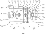
На фиг. 1 и 2 соответственно показана схема принадлежащей заявителю групповой коробки передач так называемого семейства AS-Tronic. Изображенная на фиг. 1 и 2 групповая коробка СТ передач содержит основную коробку HG передач, установленный с точки зрения привода перед основной коробкой HG передач делитель GV, а также установленный за основной коробкой HG передач задний делитель GP. Основная коробка HG передач групповой коробки СТ передач согласно фиг. 1 и 2 выполнена как коробка HG с прямой передачей в конструкции с промежуточными валами и имеет вторичный вал WH и два промежуточных вала WVG1 и WVG2, при этом первый промежуточный вал WVG1 снабжен управляемым воздействующим на трансмиссию тормозным механизмом Вr.In FIG. 1 and 2 respectively show a diagram of a group gearbox belonging to the applicant of the so-called AS-Tronic family. Depicted in FIG. 1 and 2, the group gearbox CT of the gearbox contains the main gearbox HG, installed from the point of view of the drive in front of the main gearbox HG gearshift divider GV, as well as the rear gearshift GP installed behind the main gearbox HG. The main gearbox HG of the group transmission gearbox ST according to FIG. 1 and 2 are designed as a direct-drive gearbox HG in a design with countershafts and have a secondary shaft W H and two countershafts W VG1 and W VG2 , while the first countershaft W VG1 is equipped with a transmission-controlled brake mechanism Br.
Основная коробка HG передач выполнена трехступенчатой с тремя ступенями G1, G2 и G3 для движения вперед и одной ступенью R для движения назад. Свободные шестерни ступеней G1, G2 и R соответственно установлены с возможностью вращения на вторичном валу WH и с возможностью включения через приданные им кулачковые муфты. Фиксированные шестерни установлены без возможности вращения на промежуточных валах WVG1 и WVG2.The main gearbox HG is made in three stages with three stages G1, G2 and G3 for forward movement and one stage R for reverse movement. The free gears of the steps G1, G2 and R are respectively mounted rotatably on the secondary shaft W H and can be switched on via cam clutches attached to them. The fixed gears are mounted rotatably on the intermediate shafts W VG1 and W VG2 .
Выполненная в виде прямой передачи наивысшая ступень G3 основной коробки HG передач является включаемой через муфту прямого включения. Муфты переключения ступеней G3 и G2, а также муфты переключения ступеней G1 и R сосредоточены соответственно в одном общем пакете S1 или же S2 переключения. Основная коробка HG передач является переключаемой несинхронизировано.Made in the form of a direct transmission, the highest stage G3 of the main gearbox HG is switched on via a direct connection clutch. The switching clutches of the stages G3 and G2, as well as the switching clutches of the stages G1 and R, are respectively concentrated in one common switching packet S1 or S2. The main HG gearbox is shiftable unsynchronized.
Делитель GV групповой коробки СТ передач согласно фиг. 1 и 2 выполнен двухступенчатым и тоже в конструкции с промежуточными валами, при этом обе ступени К1 и К2 делителя GV образуют две переключаемых входных константы основной коробки HG передач. За счет меньшей разности передаточных чисел обеих ступеней К1, К2 группа GV рассчитана как делитель. Свободная шестерня первой ступени К1 установлена с возможностью вращения на входном валу WGE, который посредством управляемого разделительного сцепления К находится в соединении с не показанным, выполненным в виде двигателя внутреннего сгорания приводным агрегатом.The gearbox divider GV of the PT gearbox according to FIG. 1 and 2 are made in two stages and also in a construction with intermediate shafts, while both stages K1 and K2 of the divider GV form two switchable input constants of the main gearbox HG. Due to the smaller difference in gear ratios of both stages K1, K2, group GV is calculated as a divider. The free gear of the first stage K1 is rotatably mounted on the input shaft W GE , which, by means of a controlled separation clutch K, is connected to a drive unit not shown, made in the form of an internal combustion engine.
Свободная шестерня второй ступени К2 установлена с возможностью вращения на вторичном валу WH. Фиксированные шестерни обеих ступеней К1, К2 делителя GV соответственно расположены без возможности вращения с удлиненными со стороны входа промежуточными валами WVG1 и WVG2 основной коробки передач. Выполненные синхронизированными муфты переключения передач делителя GV сосредоточены в совместном пакете SV переключений. На фиг. 1 показан делитель GV в нейтральном положении, а на фиг. 2 - в положении с силовым замыканием.The free gear of the second stage K2 is mounted rotatably on the secondary shaft W H. The fixed gears of both stages K1, K2 of the divider GV are respectively rotatably located with the intermediate shafts W VG1 and W VG2 of the main gearbox extended from the input side. The synchronized gearshift clutches made by the GV divider are concentrated in a joint SV gearshift package. In FIG. 1 shows the GV divider in the neutral position, and FIG. 2 - in position with power circuit.
Расположенный за основной коробкой HG передач задний делитель GP групповой коробки СТ передач согласно фиг. 1 и 2 также выполнен двухступенчатым, однако в планетарной конструкции с простым набором планетарных шестерен. Солнечная шестерня PS без возможности вращения соединена с удлиненным с выходной стороны вторичным валом WH основной коробки HG передач. Водило РТ планетарной передачи без возможности вращения соединено с выходным валом WGA групповой коробки СТ передач. Коронная шестерня РН находится в соединении с пакетом SP переключений с двумя синхронизированными муфтами переключения передач, посредством которых задний делитель GP является выборочно переключаемым посредством соединения коронной шестерни РН с неподвижной корпусной деталью в ступень L медленного движения, а посредством соединения коронной шестерни РН с вторичным валом WH или же солнечной шестерней PS в ступень S быстрого движения. Задний делитель GP является синхронизировано переключаемым.Located behind the main gearbox HG, the rear splitter GP of the group transmission gearbox ST according to FIG. 1 and 2 are also made in two stages, however, in a planetary design with a simple set of planetary gears. The sun gear PS is rotatably connected to the secondary shaft W H of the main gearbox HG extended on the output side elongated on the output side. The planet carrier PT of the planetary gear is rotationally connected to the output shaft W GA of the group transmission gearbox ST. The ring gear PH is connected to the gearshift package SP with two synchronized gearshift clutches, by means of which the rear gear divider GP is selectively switched by connecting the ring gear of the pH with the stationary body part to the slow speed step L, and by connecting the ring gear of the pH to the secondary shaft W H or the sun gear PS to step S of fast movement. The rear GP divider is synchronously switchable.
Тогда, когда автомобиль с групповой коробкой СТ передач согласно фиг. 1 и 2 ставится на стоянку с выключенным приводным агрегатом, делитель GV групповой коробки СТ передач типично занимает показанное на фиг. 2 положение с силовым замыканием. Если затем приводной агрегат запускается, то, чтобы облегчит его запуск, разделительное сцепление К разобщается, так как в том случае, если при запуске приводного агрегата делитель GV занимает показанное на фиг. 2 положение с силовым замыканием, при замкнутом сцеплении неизбежно заодно приводится в движение множество шестерен и валов, так, например, оба промежуточных вала WVG1 и WVG2. Чтобы предотвратить это, в соответствии с практикой для запуска приводного агрегата разделительное сцепление К разобщается, а именно, через исполнительный механизм сцепления. При низких температурах окружающей среды ниже -20°С при заданных обстоятельствах разделительное сцепление К больше не может быть разобщено исполнительным механизмом сцепления. Так как, кроме того, при таких низких температурах окружающей среды повышается вязкость масла в групповой коробке СТ передач, при запуске приводного агрегата в групповой коробке СТ передач должно преодолеваться большое сопротивление, которые при заданных обстоятельствах настолько велико, что приводной агрегат более не может быть запущен.Then, when the car with the group gearbox ST of the gears according to FIG. 1 and 2 are parked with the drive unit turned off, the divider GV of the group transmission gearbox ST typically occupies the position shown in FIG. 2 position with power circuit. If, then, the drive unit starts up, then, to facilitate its start-up, the separation clutch K is disconnected, since in the case when the drive unit starts up, the divider GV occupies the one shown in FIG. 2 position with a power circuit, when the clutch is closed, inevitably at the same time many gears and shafts are driven, for example, both intermediate shafts W VG1 and W VG2 . In order to prevent this, in accordance with the practice of starting the drive unit, the separation clutch K is disengaged, namely, through the clutch actuator. At low ambient temperatures below -20 ° C under the given circumstances, the clutch release K can no longer be disconnected by the clutch actuator. Since, in addition, at such low ambient temperatures, the viscosity of the oil in the group box of ST transmissions increases, when starting the drive unit in the group box of ST transmissions, great resistance must be overcome, which under given circumstances is so great that the drive unit can no longer be started .
Поэтому существует потребность в способе эксплуатации групповой коробки передач трансмиссии автомобиля, с помощью которого при низких температурах окружающей среды может быть обеспечен надежный запуск приводного агрегата.Therefore, there is a need for a method of operating a group transmission of a vehicle’s transmission, with which a reliable start-up of the drive unit can be ensured at low ambient temperatures.
Из DE 197 26 567 А1 известен способ эксплуатации групповой коробки передач автомобиля, в котором является возможной синхронизация вторичного вала групповой коробки передач при выполнении переключения.From DE 197 26 567 A1, a method for operating a group transmission of a car is known, in which it is possible to synchronize the secondary shaft of a group transmission during a shift.
DE 103 25 666 А1 раскрывает способ эксплуатации обычной коробки передач автомобиля, при котором для защиты коробки передач при холодном пуске в зависимости от уровня температуры целенаправленно ограничивается функциональность коробки передач.DE 103 25 666 A1 discloses a method of operating a conventional automobile gearbox, in which the functionality of the gearbox is purposefully limited to protect the gearbox during cold start-up depending on the temperature level.
Исходя из этого, в основе настоящего изобретения лежит проблема создания нового способа эксплуатации групповой коробки передач автомобиля.Based on this, the present invention is based on the problem of creating a new method of operating a group transmission of a car.
Эта проблема в соответствии с первым аспектом изобретения решена посредством способа по пункту 1 формулы изобретения. В соответствии с ним для пуска приводного агрегата установленный перед основной коробкой передач делитель и/или установленный перед ней задний делитель переводят в нейтральное положение.This problem in accordance with the first aspect of the invention is solved by the method according to claim 1. In accordance with it, to start the drive unit, the divider installed in front of the main gearbox and / or the rear divider installed in front of it are put into a neutral position.
В соответствии со вторым аспектом изобретения эта проблема решена посредством способа по пункту 8 формулы изобретения. В соответствии с ним при выключении приводного агрегата установленный перед основной коробкой передач делитель и/или установленный перед ней задний делитель переводят в нейтральное положение.According to a second aspect of the invention, this problem is solved by the method of claim 8. In accordance with it, when the drive unit is turned off, the divider installed in front of the main gearbox and / or the rear divider installed in front of it are transferred to the neutral position.
Общим для обоих аспектов настоящего изобретения является то, что установленный перед основной коробкой передач делитель и/или установленный перед ней задний делитель переводится в нейтральное положение для того, чтобы даже при низких температурах окружающей среды обеспечивать беспроблемный запуск приводного агрегата содержащей групповую коробку передач трансмиссии.A common feature of both aspects of the present invention is that the splitter installed in front of the main gearbox and / or the rear splitter mounted in front of it is put into a neutral position so that, even at low ambient temperatures, the drive unit containing the group transmission has a trouble-free start-up.
В соответствии с первым аспектом настоящего изобретения для этого для пуска приводного агрегата установленный перед основной коробкой передач делитель и/или установленный перед ней задний делитель переводится в нейтральное положение, причем указанный перевод делителя и/или заднего делителя в нейтральное положение выполняют исключительно при наличии заданных условий эксплуатации трансмиссии для запуска приводного агрегата, если не может быть разобщено разделительное сцепление, предпочтительно после включения зажигания. В соответствии со вторым аспектом настоящего изобретения при выключении приводного агрегата установленный перед основной коробкой передач делитель и/или установленный перед ней задний делитель переводится в нейтральное положение.In accordance with the first aspect of the present invention, for this to start the drive unit, a divider installed in front of the main gearbox and / or a rear divider installed in front of it is put into neutral position, and said divider and / or rear divider is put into neutral position only under specified conditions operation of the transmission to start the drive unit, if the separation clutch cannot be disconnected, preferably after ignition is turned on. According to a second aspect of the present invention, when the drive unit is turned off, a divider installed in front of the main gearbox and / or a rear divider installed in front of it is put into a neutral position.
Предпочтительные усовершенствования изобретения следуют из зависимых пунктов формулы и нижеследующего описания. Пример осуществления изобретения, более детально поясняется на чертежах, на которых показано:Preferred improvements of the invention result from the dependent claims and the following description. An example embodiment of the invention is explained in more detail in the drawings, which show:
Фиг.1: схема групповой коробки передач в первом состоянии переключения делителя; иFigure 1: diagram of a group gearbox in a first state of switching a divider; and
Фиг.2: схема групповой коробки передач во втором состоянии переключения делителя.Figure 2: diagram of a group gearbox in the second state of switching the divider.
Настоящее изобретение относится к способу эксплуатации групповой коробки передач автомобиля, прежде всего показанной на фиг.1 и 2, уже детально описанной автоматической групповой коробки СТ передач. Способ согласно изобретению относится к таким деталям, с помощью которых приводной агрегат может быть запущен без проблем.The present invention relates to a method for operating a group transmission of a car, primarily shown in FIGS. 1 and 2, of the automatic group transmission CT of gears already described in detail. The method according to the invention relates to such parts by which the drive unit can be started without problems.
В соответствии с первым аспектом настоящего изобретения тогда, когда трансмиссия, которая содержит приводной агрегат и групповую коробку СТ передач, прежде всего согласно фиг.1 и 2, должна быть запущена, для пуска приводного агрегата установленный перед основной коробкой HG передач делитель GV переводится в нейтральное положение. За счет этого обеспечивается, что для пуска приводного агрегата подлежащие вращению в коробке передач валы и шестерни уменьшаются до абсолютного минимума для того, чтобы таким образом свести к минимуму сопротивление групповой коробки СТ передач при пуске приводного агрегата.In accordance with the first aspect of the present invention, when the transmission, which contains the drive unit and the group gearbox ST of the gears, primarily according to FIGS. 1 and 2, must be started, to start the drive unit, the divider GV installed in front of the main gearbox HG is converted to neutral position. This ensures that to start the drive unit shafts and gears to be rotated in the gearbox are reduced to an absolute minimum in order to minimize the resistance of the group transmission gearbox ST when starting the drive unit.
В соответствии с первым благоприятным усовершенствованием первого аспекта настоящего изобретения для пуска приводного агрегата установленный перед основной коробкой HG передач делитель GV переводится в нейтральное положение согласно фиг.1 исключительно при наличии заданных условий эксплуатации трансмиссии. Так, например, может быть предусмотрено, что делитель GV переводится в нейтральное положение согласно фиг.1 для пуска приводного агрегата только тогда, когда при пуске приводного агрегата температура окружающей среды или температура коробки передач меньше заданной предельной величины, например меньше, чем -20°C. В качестве альтернативы или дополнительно, делитель GV для пуска приводного агрегата может быть переведен в нейтральное положение тогда, когда при пуске приводного агрегата не может быть разобщено разделительное сцепление К, при этом это может быть обнаружено, например, с помощью приданного разделительному сцеплению К датчика, который контролирует положение разделительного сцепления К. В качестве альтернативы или дополнительно, делитель GV для пуска приводного агрегата может быть переведен в нейтральное положение тогда, когда при предшествующем процессе пуска приводной агрегат не мог быть запущен.According to a first advantageous development of the first aspect of the present invention, for starting the drive unit, the divider GV installed in front of the main gearbox HG is brought into the neutral position according to FIG. 1 solely in the presence of predetermined transmission operating conditions. So, for example, it can be provided that the divider GV is brought to the neutral position according to FIG. 1 for starting the drive unit only when, when starting the drive unit, the ambient temperature or the temperature of the gearbox is less than a predetermined limit value, for example less than -20 ° C. Alternatively or additionally, the divider GV for starting the drive unit can be put into neutral position when the separation clutch K cannot be disconnected when starting the drive unit, and this can be detected, for example, using a sensor attached to the clutch clutch K, which controls the position of the clutch release K. Alternatively or additionally, the GV divider for starting up the drive unit can be put into neutral when stvuyuschem during start-up drive unit can not be started.
В соответствии со вторым благоприятным усовершенствованием первого аспекта настоящего изобретения также является возможным, при каждом процессе пуска приводного агрегата переводить установленный перед основной коробкой HG передач делитель GV в нейтральное положение согласно фиг.1.According to a second advantageous development of the first aspect of the present invention, it is also possible, at each start-up process of the drive unit, to put the divider GV installed in front of the main gearbox HG into the neutral position according to FIG.
Перевод делителя GV в нейтральное положение для пуска приводного агрегата в соответствии с первым аспектом изобретения происходит каждый раз после включения зажигания.The transfer of the GV divider to the neutral position for starting the drive unit in accordance with the first aspect of the invention occurs each time after ignition is turned on.
Таким образом, в соответствии с первым аспектом настоящего изобретения для пуска приводного агрегата делитель GV групповой коробки СТ передач переводится в нейтральное положение согласно фиг.1. При этом стартер должен приводить в движение только входной вал WGE групповой коробки СТ передач вместе с ведомым диском сцепления и не показанным подшипником. Промежуточные валы WVG1 и WVG2, все входящие в зацепление с зубчатыми венцами промежуточной передачи шестерни и подшипники, напротив, остаются неподвижными, в результате чего может быть явно уменьшено сопротивление, которое оказывает групповая коробка СТ передач при пуске приводного агрегата.Thus, in accordance with the first aspect of the present invention, to start the drive unit, the splitter GV of the group transmission CT is shifted to the neutral position according to FIG. In this case, the starter should only drive the input shaft W GE of the group transmission CT transmission together with the clutch plate and the bearing not shown. The intermediate shafts W VG1 and W VG2 , all gears and bearings engaged with the gears of the intermediate gear, on the contrary, remain stationary, as a result of which the resistance of the group transmission gearbox when starting the drive unit can be clearly reduced.
Предпочтительно, для пуска приводного агрегата происходит перевод делителя GV в нейтральное положение при низких температурах окружающей среды или же низких температурах коробки передач, которые ниже заданной предельной величины температуры. При относительно долгой стоянке автомобиля температура коробки передач примерно соответствует температуре окружающей среды.Preferably, to start the drive unit, the GV divider is brought to a neutral position at low ambient temperatures or low gearbox temperatures that are below a predetermined temperature limit. When the vehicle is parked for a relatively long time, the gearbox temperature is approximately the same as the ambient temperature.
В том случае, если перед основной коробкой HG передач установлен задний делитель, для пуска приводного агрегата задний делитель переводится в нейтральное положение. В том случае, если перед основной коробкой HG передач установлено несколько делителей, например, делитель и задний делитель, для пуска приводного агрегата в нейтральное положение переводится по меньшей мере тот делитель, пакет переключения которого посредством входного вала групповой коробки передач соединен с ведомым диском разделительного сцепления К. На фиг. 1 и 2 это относится к пакету SV переключения делителя GV.In the event that a rear divider is installed in front of the main HG gearbox, the rear divider is set to the neutral position to start the drive unit. In the event that several dividers are installed in front of the main HG gearbox, for example, a divider and a rear divider, at least the divider is switched to start the drive unit in the neutral position, the switching package of which is connected to the driven clutch disc by the input shaft of the group gearbox K. In FIG. 1 and 2 this refers to the SV packet of switching the GV divider.
В соответствии со вторым аспектом настоящего изобретения при выключении приводного агрегата установленный перед основной коробкой передач делитель GV переводится в нейтральное положение.According to a second aspect of the present invention, when the drive unit is turned off, the divider GV installed in front of the main gearbox is put into neutral position.
В соответствии с первым благоприятным усовершенствованием второго аспекта настоящего изобретения это может происходить исключительно при наличии заданных условий эксплуатации трансмиссии или в соответствии со вторым благоприятным усовершенствованием второго аспекта изобретения при каждом выключении приводного агрегата. В том случае, если при выключении приводного агрегата делитель переводится в нейтральное положение исключительно при наличии заданных условий эксплуатации для трансмиссии, это происходит тогда, когда температура окружающей среды при постановке автомобиля на стоянку и тем самым при выключении приводного агрегата меньше, чем заданная предельная величина, например, меньше чем -20°С. Тем самым может быть обеспечено, что при последующем запуске приводного агрегата делитель GV групповой коробки СТ передач уже занимает нейтральное положение, и поэтому при запуске приводного агрегата должно быть преодолено лишь небольшое сопротивление групповой коробки СТ передач.In accordance with the first favorable improvement of the second aspect of the present invention, this can happen solely in the presence of predetermined transmission operating conditions or in accordance with the second favorable improvement of the second aspect of the invention each time the drive unit is turned off. In the event that when the drive unit is turned off, the divider is brought to the neutral position only if the specified operating conditions for the transmission are present, this happens when the ambient temperature when parking the vehicle and thereby when the drive unit is turned off is less than the specified limit value, for example, less than -20 ° C. Thereby, it can be ensured that the next time the drive unit is started, the divider GV of the group transmission gearbox ST is already in a neutral position, and therefore, when starting the drive unit, only a small resistance of the group transmission gearbox ST should be overcome.
В том случае, когда при реализации первого благоприятного усовершенствования второго аспекта настоящего изобретения автомобиль не имеет собственного температурного датчика для измерения температуры окружающей среды, при запуске приводного агрегата может быть сохранена температура коробки передач, которая при запуске приводного агрегата примерно соответствует температуре окружающей среды для того, чтобы при следующем выключении приводного агрегата перевести делитель GV групповой коробки СТ передач в нейтральное положение тогда, когда сохраненная при последнем запуске приводного агрегата температура меньше, чем заданная, заданная предельная величина. Если же автомобиль имеет отдельный датчик температуры окружающей среды, то в зависимости от измеренной им температуры окружающей среды может происходить перевод делителя GV в нейтральное положение.In the case when, when implementing the first favorable improvement of the second aspect of the present invention, the car does not have its own temperature sensor for measuring the ambient temperature, when starting the drive unit, the temperature of the gearbox can be stored, which when starting the drive unit is approximately the same as the ambient temperature, so that the next time the drive unit is turned off, put the divider GV of the group transmission ST gear in neutral position, then where the temperature stored during the last start of the drive unit is less than the set, set limit value. If the car has a separate ambient temperature sensor, then depending on the ambient temperature measured by it, the GV divider may be switched to the neutral position.
В соответствии с первым аспектом настоящего изобретения второй аспект настоящего изобретения может быть применен и в случае с групповыми коробками передач, в котором перед их основной коробкой передач установлены задний делитель или делитель и задний делитель. В том случае, если перед основной коробкой HG передач установлен задний делитель, при выключении приводного агрегата задний делитель переводится в нейтральное положение. В том случае, если перед основной коробкой HG передач установлено несколько делителей, например делитель и задний делитель, при выключении приводного агрегата в нейтральное положение переводится по меньшей мере тот делитель, пакет переключения которого посредством входного вала групповой коробки передач соединен с ведомым диском разделительного сцепления К. На фиг. 1 это относится к пакету SV переключения делителя GV.In accordance with the first aspect of the present invention, the second aspect of the present invention can be applied in the case of group transmissions in which a rear divider or a divider and a rear divider are installed in front of their main gearbox. In the event that a rear splitter is installed in front of the main HG gearbox, when the drive unit is turned off, the rear splitter is switched to the neutral position. In the event that several dividers are installed in front of the main HG gearbox, for example, a divider and a rear divider, when the drive unit is turned off, at least that divider is switched into a neutral position, the switching package of which is connected to the driven disc of the separation clutch K via the input shaft of the group gearbox In FIG. 1 this refers to the GV divider switch SV packet.
Claims (11)
Applications Claiming Priority (3)
| Application Number | Priority Date | Filing Date | Title |
|---|---|---|---|
| DE102009001030.0 | 2009-02-20 | ||
| DE102009001030A DE102009001030A1 (en) | 2009-02-20 | 2009-02-20 | Method for operating a group transmission |
| PCT/EP2010/050148 WO2010094518A1 (en) | 2009-02-20 | 2010-01-08 | Method for operating a group transmission |
Publications (2)
| Publication Number | Publication Date |
|---|---|
| RU2011138068A RU2011138068A (en) | 2013-03-27 |
| RU2534603C2 true RU2534603C2 (en) | 2014-11-27 |
Family
ID=41719017
Family Applications (1)
| Application Number | Title | Priority Date | Filing Date |
|---|---|---|---|
| RU2011138068/11A RU2534603C2 (en) | 2009-02-20 | 2010-01-08 | Method of group transmission operation |
Country Status (6)
| Country | Link |
|---|---|
| US (1) | US20110296937A1 (en) |
| EP (1) | EP2399049B1 (en) |
| CN (1) | CN102326015B (en) |
| DE (1) | DE102009001030A1 (en) |
| RU (1) | RU2534603C2 (en) |
| WO (1) | WO2010094518A1 (en) |
Families Citing this family (6)
| Publication number | Priority date | Publication date | Assignee | Title |
|---|---|---|---|---|
| DE102014202381A1 (en) * | 2014-02-11 | 2015-08-13 | Zf Friedrichshafen Ag | Method for operating a transmission device |
| WO2018158713A1 (en) * | 2017-02-28 | 2018-09-07 | Eaton Intelligent Power Limited | System, method, and apparatus for managing transmission shutdown operations |
| US11105412B2 (en) | 2016-12-22 | 2021-08-31 | Eaton Cummins Automated Transmission Technologies Llc | System, method, and apparatus for managing transmission shutdown operations |
| WO2018118131A1 (en) | 2016-12-22 | 2018-06-28 | Eaton Corporation | System, method, and apparatus for operating a high efficiency, high output transmission |
| US10584778B2 (en) | 2016-12-22 | 2020-03-10 | Eaton Cummins Automated Transmission Technologies, Llc | High efficiency, high output transmission |
| WO2019091953A1 (en) * | 2017-11-09 | 2019-05-16 | Cnh Industrial Italia S.P.A. | Improvements in or relating to dual-clutch transmissions |
Citations (4)
| Publication number | Priority date | Publication date | Assignee | Title |
|---|---|---|---|---|
| EP1101980A2 (en) * | 1999-11-10 | 2001-05-23 | Isuzu Motors Limited | Multi-stage transmission for a vehicle |
| EP1662185A1 (en) * | 2004-11-26 | 2006-05-31 | ZF FRIEDRICHSHAFEN Aktiengesellschaft | Method and control device to securely interrupt the power flow in a driveline |
| RU2321506C2 (en) * | 2003-07-25 | 2008-04-10 | Хюн-Ох ШИН | System for and method of safe starting of automobile |
| WO2010027321A1 (en) * | 2008-09-08 | 2010-03-11 | Scania Cv Ab (Publ) | Method and computer programme product for improving performance of a motor vehicle |
Family Cites Families (11)
| Publication number | Priority date | Publication date | Assignee | Title |
|---|---|---|---|---|
| DE19726567B4 (en) | 1997-06-23 | 2006-12-21 | Zf Friedrichshafen Ag | Transmission main shaft synchronization method |
| US6732529B2 (en) * | 2001-11-16 | 2004-05-11 | Pratt & Whitney Canada Corp. | Off loading clutch for gas turbine engine starting |
| SE523670C2 (en) * | 2002-09-09 | 2004-05-11 | Volvo Lastvagnar Ab | Stepper gearbox for motor vehicles |
| DE10325666A1 (en) | 2003-06-06 | 2004-12-23 | Zf Friedrichshafen Ag | Protecting gearbox of motor vehicle during a cold start involves implementing protection functions for one or more temperature stages by limiting gearbox functions depending on temperature stages |
| JP4459645B2 (en) * | 2004-02-09 | 2010-04-28 | 株式会社 神崎高級工機製作所 | PTO transmission structure |
| DE102005002496A1 (en) * | 2005-01-19 | 2006-07-27 | Zf Friedrichshafen Ag | Method for switching control of an automated manual transmission |
| DE102006024370A1 (en) * | 2006-05-24 | 2007-12-13 | Zf Friedrichshafen Ag | Multi-group transmission and method for changing gears in a multi-group transmission |
| DE102006043333A1 (en) * | 2006-09-15 | 2008-03-27 | Daimler Ag | Commercial vehicle transmission with a main group and a rear group |
| DE102007010827A1 (en) * | 2007-03-06 | 2008-09-11 | Zf Friedrichshafen Ag | Method for switching control of an automated group transmission |
| DE102007010829A1 (en) * | 2007-03-06 | 2008-09-11 | Zf Friedrichshafen Ag | Method for switching control of an automated group transmission |
| US8140231B2 (en) * | 2007-11-22 | 2012-03-20 | Nissan Motor Co., Ltd. | Abnormal-period automatic shift control apparatus of automated manual transmission |
-
2009
- 2009-02-20 DE DE102009001030A patent/DE102009001030A1/en not_active Withdrawn
-
2010
- 2010-01-08 EP EP10700316.2A patent/EP2399049B1/en not_active Not-in-force
- 2010-01-08 US US13/143,384 patent/US20110296937A1/en not_active Abandoned
- 2010-01-08 RU RU2011138068/11A patent/RU2534603C2/en not_active IP Right Cessation
- 2010-01-08 WO PCT/EP2010/050148 patent/WO2010094518A1/en not_active Ceased
- 2010-01-08 CN CN201080008871.8A patent/CN102326015B/en not_active Expired - Fee Related
Patent Citations (4)
| Publication number | Priority date | Publication date | Assignee | Title |
|---|---|---|---|---|
| EP1101980A2 (en) * | 1999-11-10 | 2001-05-23 | Isuzu Motors Limited | Multi-stage transmission for a vehicle |
| RU2321506C2 (en) * | 2003-07-25 | 2008-04-10 | Хюн-Ох ШИН | System for and method of safe starting of automobile |
| EP1662185A1 (en) * | 2004-11-26 | 2006-05-31 | ZF FRIEDRICHSHAFEN Aktiengesellschaft | Method and control device to securely interrupt the power flow in a driveline |
| WO2010027321A1 (en) * | 2008-09-08 | 2010-03-11 | Scania Cv Ab (Publ) | Method and computer programme product for improving performance of a motor vehicle |
Also Published As
| Publication number | Publication date |
|---|---|
| CN102326015A (en) | 2012-01-18 |
| US20110296937A1 (en) | 2011-12-08 |
| RU2011138068A (en) | 2013-03-27 |
| WO2010094518A1 (en) | 2010-08-26 |
| DE102009001030A1 (en) | 2010-08-26 |
| EP2399049A1 (en) | 2011-12-28 |
| EP2399049B1 (en) | 2013-05-01 |
| CN102326015B (en) | 2014-05-14 |
Similar Documents
| Publication | Publication Date | Title |
|---|---|---|
| US8161835B2 (en) | Multi-group transmission and method for changing gear in a multi-group transmission | |
| CN101622479B (en) | Method for switching control of automated combinatory transmission | |
| US8197380B2 (en) | Motor vehicle automated gearbox and method for the operation thereof | |
| US7976431B2 (en) | Method for shifting actuation of an automated group transmission | |
| US8561493B2 (en) | Automated multi-group transmission of a motor vehicle and method for operating an automated multi-group transmission | |
| US8230752B2 (en) | Automatic group transmission | |
| US7632211B2 (en) | Shift control method for an automatic gearbox | |
| US7878942B2 (en) | Method for shifting actuation of an automated transmission | |
| US8066606B2 (en) | Multi-group transmission of a motor vehicle | |
| US9239106B2 (en) | Method for running a drive line | |
| US8444528B2 (en) | Method for operating a drive train | |
| RU2534603C2 (en) | Method of group transmission operation | |
| US8069742B2 (en) | Multi-group transmission of a motor vehicle | |
| US20090272211A1 (en) | Multi-group transmission of a motor vehicle | |
| US9068636B2 (en) | Multigroup transmission of a motor vehicle | |
| KR20190046049A (en) | Power transmission apparatus for vehicle | |
| US8979707B2 (en) | Method for operating a drive train | |
| US20080245168A1 (en) | Automatic Transmission and Shift Control Method For Said Transmission | |
| US20130053204A1 (en) | Gearbox arrangement which comprises a first gearbox with an adjoining range gearbox | |
| CN101617148A (en) | Method for operating a vehicle driveline | |
| US20090266190A1 (en) | Multi-group transmission of a motor vehicle | |
| US20030125156A1 (en) | Shift control method for an automatic transmission | |
| JP2003287088A (en) | Automatic transmission | |
| US20090280956A1 (en) | Multi-group transmission of a motor vehicle | |
| CN116964360B (en) | Method and control device for operating a drive train |
Legal Events
| Date | Code | Title | Description |
|---|---|---|---|
| MM4A | The patent is invalid due to non-payment of fees |
Effective date: 20150109 |