RU2532557C2 - Device and method for lubricant feed - Google Patents
Device and method for lubricant feed Download PDFInfo
- Publication number
- RU2532557C2 RU2532557C2 RU2012122508/05A RU2012122508A RU2532557C2 RU 2532557 C2 RU2532557 C2 RU 2532557C2 RU 2012122508/05 A RU2012122508/05 A RU 2012122508/05A RU 2012122508 A RU2012122508 A RU 2012122508A RU 2532557 C2 RU2532557 C2 RU 2532557C2
- Authority
- RU
- Russia
- Prior art keywords
- lubricant
- mixing
- cartridge
- chamber
- cleaning rod
- Prior art date
Links
Images

Classifications
-
- B—PERFORMING OPERATIONS; TRANSPORTING
- B05—SPRAYING OR ATOMISING IN GENERAL; APPLYING FLUENT MATERIALS TO SURFACES, IN GENERAL
- B05B—SPRAYING APPARATUS; ATOMISING APPARATUS; NOZZLES
- B05B7/00—Spraying apparatus for discharge of liquids or other fluent materials from two or more sources, e.g. of liquid and air, of powder and gas
- B05B7/02—Spray pistols; Apparatus for discharge
-
- B—PERFORMING OPERATIONS; TRANSPORTING
- B05—SPRAYING OR ATOMISING IN GENERAL; APPLYING FLUENT MATERIALS TO SURFACES, IN GENERAL
- B05B—SPRAYING APPARATUS; ATOMISING APPARATUS; NOZZLES
- B05B17/00—Apparatus for spraying or atomising liquids or other fluent materials, not covered by the preceding groups
-
- B—PERFORMING OPERATIONS; TRANSPORTING
- B29—WORKING OF PLASTICS; WORKING OF SUBSTANCES IN A PLASTIC STATE IN GENERAL
- B29B—PREPARATION OR PRETREATMENT OF THE MATERIAL TO BE SHAPED; MAKING GRANULES OR PREFORMS; RECOVERY OF PLASTICS OR OTHER CONSTITUENTS OF WASTE MATERIAL CONTAINING PLASTICS
- B29B7/00—Mixing; Kneading
- B29B7/74—Mixing; Kneading using other mixers or combinations of mixers, e.g. of dissimilar mixers ; Plant
- B29B7/76—Mixers with stream-impingement mixing head
- B29B7/7663—Mixers with stream-impingement mixing head the mixing head having an outlet tube with a reciprocating plunger, e.g. with the jets impinging in the tube
- B29B7/7678—Mixers with stream-impingement mixing head the mixing head having an outlet tube with a reciprocating plunger, e.g. with the jets impinging in the tube of the gun type, i.e. hand-held units
-
- B—PERFORMING OPERATIONS; TRANSPORTING
- B29—WORKING OF PLASTICS; WORKING OF SUBSTANCES IN A PLASTIC STATE IN GENERAL
- B29B—PREPARATION OR PRETREATMENT OF THE MATERIAL TO BE SHAPED; MAKING GRANULES OR PREFORMS; RECOVERY OF PLASTICS OR OTHER CONSTITUENTS OF WASTE MATERIAL CONTAINING PLASTICS
- B29B7/00—Mixing; Kneading
- B29B7/74—Mixing; Kneading using other mixers or combinations of mixers, e.g. of dissimilar mixers ; Plant
- B29B7/76—Mixers with stream-impingement mixing head
- B29B7/7663—Mixers with stream-impingement mixing head the mixing head having an outlet tube with a reciprocating plunger, e.g. with the jets impinging in the tube
- B29B7/7684—Parts; Accessories
- B29B7/7689—Plunger constructions
Abstract
Description
Настоящее изобретение относится к устройствам подачи нескольких компонентов и, более конкретно, к смазке стержня механической очистки устройства подачи нескольких компонентов.The present invention relates to multiple component feed devices and, more particularly, to the lubrication of a mechanical cleaning rod of a multiple component feed device.
Обычно несколько компонентов, к подаче которых относится настоящее изобретение, представляют собой смолу, которая сама по себе химически инертна, и изоцианатный материал, который также сам по себе химически инертен. Когда изоцианат и смолу соединяют, то немедленно начинается химическая реакция, в результате которой происходит перекрестное сшивание, схватывание и отвердение смеси. Поэтому два компонента подаются в подающем устройстве раздельно до наконечника, в котором они смешиваются и из которого они подаются наружу. В промежутках между подачами отдельных порций смеси зону смешивания и наконечник подающего устройства необходимо очищать от смеси, поскольку в противном случае она будет затвердевать, в результате чего работа устройства будет нарушаться. Однако очистка зоны смешивания и наконечника подающего устройства может представлять трудности в связи с высокой (и увеличивающейся) вязкостью твердеющей смеси компонентов.Typically, the several components to which the present invention relates are a resin, which itself is chemically inert, and an isocyanate material, which is also chemically inert by itself. When the isocyanate and the resin are combined, a chemical reaction immediately begins, resulting in cross-linking, setting and hardening of the mixture. Therefore, the two components are fed separately to the tip in the feeder, in which they are mixed and from which they are fed out. In the intervals between the feeds of individual portions of the mixture, the mixing zone and the tip of the feeding device must be cleaned of the mixture, because otherwise it will harden, as a result of which the device will be disturbed. However, cleaning the mixing zone and the tip of the feed device can be difficult due to the high (and increasing) viscosity of the hardening mixture of components.
КРАТКОЕ ОПИСАНИЕ ИЗОБРЕТЕНИЯSUMMARY OF THE INVENTION
В настоящем изобретении предлагается подающее устройство, содержащее смесительную головку для смешивания по меньшей мере двух текучих компонентов, с очистным стержнем, расположенным в смесительной головке с возможностью скольжения. Очистной стержень может занимать переднее положение, в котором предотвращается поток из впускных отверстий для компонентов, и заднее положение, в котором разрешается поток из впускных отверстий для компонентов, причем перемещение очистного стержня между этими положениями осуществляется приводом. Подающее устройство содержит также смазочную камеру, в которой на очистной стержень подается смазочный материал, поступающий из картриджа со смазочным материалом.The present invention provides a feed device comprising a mixing head for mixing at least two fluid components with a cleaning rod slidingly disposed in the mixing head. The cleaning rod may occupy a forward position in which flow from the component inlets is prevented, and a rear position in which flow from the component inlets is allowed, wherein the cleaning rod is moved between these positions by the drive. The supply device also contains a lubricating chamber in which lubricant is supplied to the cleaning rod from the lubricant cartridge.
В другом варианте подающее устройство имеет корпус и картридж со смазочным материалом, вставляемый в корпус. Подающее устройство содержит также внутри корпуса канал для смазочного материала, который соединен с картриджем со смазочным материалом, и смесительный механизм, прикрепленный к корпусу. Смесительный механизм предназначен для смешивания по меньшей мере двух текучих компонентов. Очистной стержень установлен в смесительном механизме с возможностью скольжения. С каналом для смазочного материала внутри корпуса соединяется другой канал для смазочного материала внутри смесительного механизма, обеспечивающий подачу смазочного материала к очистному стержню.In another embodiment, the feed device has a housing and a cartridge with lubricant inserted into the housing. The supply device also comprises a channel for lubricant inside the housing, which is connected to the cartridge with the lubricant, and a mixing mechanism attached to the housing. The mixing mechanism is designed to mix at least two fluid components. The cleaning rod is mounted in the mixing mechanism with the possibility of sliding. With the channel for lubricant inside the housing, another channel for lubricant inside the mixing mechanism is connected, which provides the supply of lubricant to the treatment rod.
В изобретении предлагается также способ осуществления работы подающего устройства, который включает обеспечение повышенного давления двух текучих компонентов и обеспечение повышенного давления в картридже со смазочным материалом, который прикреплен к подающему устройству. Способ включает также перемещение очистного стержня в заднее положение, в котором разрешается поступление потоков двух текучих компонентов в смесительную камеру, где происходит смешивание компонентов. Также способ включает непрерывное смазывание очистного стержня смазочным материалом, находящимся под давлением, в процессе работы подающего устройства, и предотвращение попадания смазочного материала в смесительную камеру.The invention also provides a method for operating a feed device, which comprises providing increased pressure to two fluid components and providing increased pressure to a lubricant cartridge that is attached to the delivery device. The method also includes moving the cleaning rod to the rear position, in which flows of two fluid components are allowed to enter the mixing chamber, where the components are mixed. The method also includes the continuous lubrication of the cleaning rod with a lubricant under pressure during operation of the feeding device, and preventing the lubricant from entering the mixing chamber.
КРАТКОЕ ОПИСАНИЕ ЧЕРТЕЖЕЙBRIEF DESCRIPTION OF THE DRAWINGS
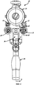
Фигура 1 - вид сбоку подающего (раздаточного) устройства и картриджа со смазочным материалом.Figure 1 is a side view of the supply (distributing) device and the cartridge with lubricant.
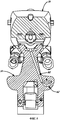
Фигура 2 - вид сзади подающего устройства, показанного на фигуре 1, со вставленным в него картриджем со смазочным материалом.Figure 2 is a rear view of the feed device shown in Figure 1, with a lubricant cartridge inserted therein.
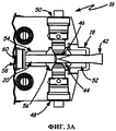
Фигура 3А - вид сверху сечения смесительной головки по линии 3-3 фигуры 1, когда смесь компонентов подается через смесительную головку, и очистной стержень находится в заднем положении.Figure 3A is a top view of the cross section of the mixing head along line 3-3 of Figure 1, when the mixture of components is fed through the mixing head, and the cleaning rod is in the rear position.
Фигура 3В - вид сверху сечения смесительной головки по линии 3-3 фигуры 1, когда прекращается подача смеси компонентов через смесительную головку, и очистной стержень находится в переднем положении.Figure 3B is a top view of the cross section of the mixing head along line 3-3 of Figure 1, when the flow of the mixture of components through the mixing head stops, and the cleaning rod is in the front position.
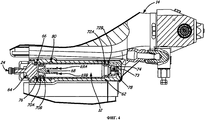
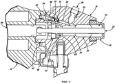
Фигура 4 - вид сбоку сечения подающего устройства по линии 4-4 фигуры 2, на котором показан смазочный цилиндр с поршнем.Figure 4 is a side view of the cross section of the feeding device along the line 4-4 of figure 2, which shows a lubricating cylinder with a piston.
Фигура 5 - вид сверху сечения подающего устройства по линии 5-5 фигуры 1, на котором показан канал для смазки.Figure 5 is a top view of the cross section of the feeding device along the line 5-5 of figure 1, which shows the channel for lubrication.
Фигура 6 - вид сбоку сечения смесительной головки по линии 6-6 фигуры 2, на котором показана смазочная камера.Figure 6 is a side view of the cross section of the mixing head along the line 6-6 of figure 2, which shows the lubrication chamber.
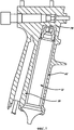
Фигура 7 - вид сбоку другого варианта подающего устройства, показанного на фигуре 2, по линии 7-7 фигуры 2, на котором показан картридж со смазкой, расположенный в ручке подающего устройства.Figure 7 is a side view of another embodiment of the feeding device shown in Figure 2, taken along line 7-7 of Figure 2, which shows a grease cartridge located in the handle of the feeding device.
ПОДРОБНОЕ ОПИСАНИЕ ИЗОБРЕТЕНИЯDETAILED DESCRIPTION OF THE INVENTION
На фигуре 1 приведен вид сбоку подающего устройства (шприца, пистолета) 10 с картриджем 12. На фигуре 2 приведен вид сзади подающего устройства 10. Как показано на фигурах 1, 2, подающее устройство 10 содержит картридж 12, цилиндр 14, смесительную головку 16, наконечник 18, очистной стержень 20, впускной патрубок 22 первого компонента, впускной патрубок 24 газа, ручку 26, спусковой крючок 28, вывод 30 управления, ввод 32 управления, смотровое окошко 34, электромагнит 36, дозирующая система 38 и впускной патрубок 40 второго компонента. Ниже приводится описание со ссылками на фигуры 1,2.The figure 1 shows a side view of the feeding device (syringe, gun) 10 with a
Основными конструктивными частями подающего устройства 10 являются: цилиндр 14, смесительная головка 16 и ручка 26. Смесительная головка 16 установлена на переднем конце цилиндра 14 и содержит наконечник 18, очистной стержень 20, впускной патрубок 22 первого компонента и впускной патрубок 40 второго компонента. Впускной патрубок 22 первого компонента и впускной патрубок 40 второго компонента подсоединяются к задней части смесительной головки 16. Наконечник 18 подсоединен к передней части смесительной головки 16, и очистной стержень 20 установлен с возможностью скольжения внутри смесительной головки 16 и наконечника 18. Ручка 26 прикреплена к нижней стороне цилиндра 14 и содержит спусковой крючок 28 и вывод 30 управления. Спусковой крючок 28 присоединен к ручке 26 с возможностью поворота, и вывод 30 управления прикреплен к задней части ручки 26.The main structural parts of the
Цилиндр 14 имеет входной патрубок 24 газа, смотровое окошко 34 и электромагнит 36. Впускной патрубок 24 газа прикреплен к задней части цилиндра 14, и смотровое окошко 34 проходит по боковой стороне цилиндра 14. Электромагнит 36 прикреплен к нижней стороне цилиндра 14, между цилиндром 14 и ручкой 26. К задней части электромагнита 36 прикреплен ввод 32 управления.The
Дозирующая система 38 соединена с подающим устройством 10, сообщаясь с впускным патрубком 22 первого компонента, впускным патрубком 24 газа и впускным патрубком 40 второго компонента. Дозирующая система 38 электрически подсоединена к подающему устройству 10 через вывод 30 управления и ввод 32 управления.The metering system 38 is connected to the
Подающее устройство 10 работает, когда пользователь нажимает на спусковой крючок 28. При этом через вывод 30 управления в дозирующую систему 38 передается электрический сигнал. Затем дозирующая система 38 через ввод 32 управления передает соответствующий сигнал в электромагнит 36. Электромагнит 36 осуществляет управление пневматической системой привода подающего устройства 10. В одном из вариантов электромагнит 36 подает газ из дозирующей системы 38 для привода газового поршня внутри цилиндра 14. Газовый поршень перемещает очистной стержень 20 назад (влево, если смотреть на фигуру 1), и в этом случае осуществляется подача смеси 42 компонентов (как описывается далее со ссылками на фигуру 3А). Когда спусковой крючок отпущен, на электромагнит 36 подаются сигналы управления для перемещения газового поршня в обратном направлении. В этом случае очистной стержень 20 перемещается вперед (направо, если смотреть на фигуру 1), в результате чего поток смеси 42 компонентов прекращается. Однако в другом варианте электромагнит 36 может быть заменен механическим золотниковым клапаном. Управление таким золотниковым клапаном осуществляется механическим перемещением спускового крючка 28 (нажатие или отпускание). В этом случае золотниковый клапан управляет пневматической системой привода, содержащей газовый поршень. Поскольку в данном случае используется механическая система управления, вывод 30 управления и ввод 32 управления исключаются.The
Сжатый газ, который обеспечивается дозирующей системой 38 и который входит через впускной патрубок 24, также используется для создания давления в картридже 12. Давление в картридже 12 создается, когда его вставляют в цилиндр 14. Картридж 12 содержит смазочный материал, который выдавливается через цилиндр 14 в смесительную головку 16, где он смазывает очистной стержень 20.Compressed gas, which is provided by the metering system 38 and which enters through the
Части и конфигурация подающего устройства 10, как показано на фигурах 1, 2, обеспечивают подачу смеси 42 нескольких компонентов из подающего устройства 10. Это происходит частично в связи с тем, что картридж 12 обеспечивает смазку очистного стержня 20. При расходовании смазочного материала в картридже 12 пользователь может видеть количество материала, остающегося в картридже 12, через смотровое окошко 34. После израсходования всего смазочного материала в картридже 12 он может быть удален, и новый картридж 12 можно вставить в подающее устройство 10 для обеспечения смазки очистного стержня 20.The parts and configuration of the
Специалисту в данной области техники будет понятно, что смазочный материал может содержать одно или несколько различных смазывающих веществ. В рассматриваемом варианте в качестве смазочного материала используется смазка TSL, предлагаемая компанией Graco Inc., г.Миннеаполис, штат Миннесота. Однако в других вариантах могут использоваться и другие смазочные материалы. Предпочтительно картридж 12 имеет прозрачный корпус или хотя бы полупрозрачный. В этом случае пользователь может видеть количество смазочного материала в картридже 12 через смотровое окошко 34.One skilled in the art will recognize that a lubricant may contain one or more different lubricants. In this embodiment, TSL grease, offered by Graco Inc., Minneapolis, Minnesota, is used as a lubricant. However, in other embodiments, other lubricants may be used. Preferably, the
На фигурах 3А, 3В приведены виды сверху сечения смесительной головки 16 по линии 3-3 фигуры 1, причем на фигуре 3а показано положение, в которое через смесительную головку 16 подается смесь 42 компонентов, а на фигуре 3В смесь 42 компонентов не подается. На фигурах 3А, 3В показаны: смесительная головка 16, наконечник 18, очистной стержень 20, смесь 42 компонентов, первый компонент 44, второй компонент 46, первая выпускная головка 48, вторая выпускная головка 50, смазочная камера 54, смесительный модуль 56, нажимная гайка 58 уплотнения и корпус 60 уплотнения.In figures 3A, 3B shows a top view of the cross section of the mixing
Как показано на фигуре 3А, первая выпускная головка 48 и вторая выпускная головка 50 прикреплены к противолежащим сторонам смесительной головки 16. Первая выпускная головка 48 и вторая выпускная головка 50 прикреплены к впускному патрубку 22 первого компонента и ко второму патрубку 40 второго компонента, соответственно (как показано на фигуре 2) и сообщаются с ними. Внутри смесительной головки 16, между первой выпускной головкой 48 и второй выпускной головкой 50, расположен смесительный модуль 56. Как уже указывалось, наконечник 18 прикреплен к передней части смесительной головки 16, и внутри наконечника 18 расположена опорная втулка 52.As shown in FIG. 3A, the
Позади смесительного модуля 56 находится смазочная камера 54. Смазочная камера 54 представляет собой полость в смесительной головке 16, содержащей смазочный материал, которая граничит впереди со смесительным модулем 56 и сзади с корпусом 60 уплотнения. Корпус 60 уплотнения находится внутри смесительной головки 16 и удерживается в нужном положении нажимной гайкой 58, которая закреплена внутри смесительной головки 16. Очистной стержень 20 установлен внутри смесительной головки 16 с возможностью скольжения, в частности, проходит внутри наконечника 18, опорной втулки 52, смесительного модуля 56, смазочной камеры 54, корпуса 60 уплотнения и зажимной гайки 58.Behind the
Смесительная головка 16 показана в положении подачи смеси 42 компонентов. Подачи смеси происходит, поскольку первый компонент 44 и второй компонент 46 подаются под давлением дозирующей системой 38 (показана на фигуре 1). Первый компонент 44 и второй компонент 46 транспортируются из дозирующей системы 38 через впускной патрубок 22 первого компонента и впускной патрубок 40 второго компонента, соответственно, и далее в первую выпускную головку 48 и вторую выпускную головку 50, соответственно. Когда очистной стержень 20 отводится к задней части подающего устройства 10, давление обеспечивает подачу первого компонента 44 и второго компонента 46 из первой выпускной головки 48 и из второй выпускной головки 50, соответственно, в смесительный модуль 56. Затем первый компонент 44 и второй компонент 50 смешиваются и формируют смесь 42 компонентов, которая начинает отвердевать. Однако смесь 42 компонентов выводится из подающего устройства 10 через опорную втулку 52 и наконечник 18 до отверждения смеси.The mixing
На фигуре 3В очистной стержень 20 показан в переднем положении. В этом положении очистной стержень 20 препятствует выходу первого компонента 44 и второго компонента 46 из первой выпускной головки 48 и из второй выпускной головки 50, соответственно. Кроме того, когда очистной стержень 20 перемещается вперед из заднего положения (показанного на фигуре 3А), он выталкивает первый компонент 44, второй компонент 46 и смесь 42 компонентов, которая находится в смесительном модуле 56, в опорной втулке 52 и в наконечнике 18.In figure 3B, the cleaning
Части и конфигурация подающего устройства 10, как показано на фигурах 3, обеспечивают смешивание первого компонента 44 и второго компонента 46 для формирования смеси 42 компонентов, которая подается из наконечника 18. Кроме прекращения потока первого компонента 44 и потока второго компонента 46 очистной стержень 20 при его перемещении вперед очищает подающее устройство 10 от твердеющей смеси 42 компонентов. В результате предотвращается возможность забивания подающего устройства 10 затвердевшей смесью 42 компонентов. Как описывается далее со ссылками на фигуры 4-7, смазочный материал подается из картриджа 12 в смазочную камеру 54 для обеспечения скольжения очистного стержня 20.The parts and configuration of the
На фигуре 4 приведен вид сбоку сечения подающего устройства 10 по линии 4-4 фигуры 2. На фигуре 4 показаны: картридж 12, цилиндр 14, впускной патрубок 24 газа, отсек 62 для картриджа, головка 64 картриджа, заднее уплотнение 66 картриджа, поршень 68 картриджа, крючки 69А, 69В поршня картриджа, уплотнения 70А, 70В поршня картриджа, передние уплотнения 72А, 72В картриджа, кольцо 73 картриджа, торцевая запечатывающая крышка 74 картриджа, вентиляционное отверстие 76 картриджа, прокалывающий элемент 78 и уплотнение 80 отсека для картриджа.The figure 4 shows a side view of the cross section of the
Картридж 12 снабжен головкой 64, прикрепленной к одному его концу. Кроме того, возле этого конца снаружи картриджа 12 расположено заднее уплотнение 66 картриджа, поршень 68 картриджа расположен внутри картриджа 12 с возможностью скольжения, и вентиляционное отверстие 76 картриджа проходит сквозь стенку картриджа 12. Уплотнения 70А, 70В поршня картриджа охватывают поршень 68, на передней части которого имеются крючки 69А, 69В, и перед поршнем 68 картриджа находится смазочный материал. На противоположном конце картриджа 12 расположены передние уплотнения 72А, 72В картриджа и кольцо 73 картриджа. К самому концу картриджа 12 прикреплена торцевая запечатывающая крышка 74 картриджа.The
Как показано на фигуре 4, картридж 12 введен в цилиндр 14, более конкретно, в полость цилиндра 14, указываемую как отсек 62 для картриджа. К цилиндру 14 у переднего конца отсека 62 для картриджа прикреплен прокалывающий элемент 78. Когда картридж 12 вставлен в отсек 62, прокалывающий элемент 78 прокалывает торцевую запечатывающую крышку 74 картриджа. В рассматриваемом варианте торцевая запечатывающая крышка 74 картриджа представляет собой металлическую фольгу, прикрепленную к торцу картриджа 12.As shown in figure 4, the
В рассматриваемом варианте головка 64 картриджа имеет лепестковые выступы, которые отходят перпендикулярно относительно центральной оси картриджа 12. В цилиндре 14 имеют соответствующие прорези, по которым эти выступы входят в отсек 62 для картриджа. После полного введения картриджа 12 в отсек 62 пользователь может повернуть картридж 12 на 90 градусов. В результате, лепестковые выступы на головке 64 будет предотвращать возможность вытягивания картриджа из отсека 62. Это связано с тем, что цилиндр 14 не имеет соответствующих прорезей, которые позволяли бы вытянуть картридж 12 из отсека 62, когда картридж повернут на 90 градусов.In the present embodiment, the
Сжатый газ из дозирующей системы 38 (как показано на фигуре 1) направляется через впускной патрубок 24 газа в отсек 62 для картриджа. В частности, газ вводится между задним уплотнением 66 картриджа и уплотнением 80 отсека картриджа, которое расположено в отсеке 62 картриджа впереди вентиляционного отверстия 76. Таким образом, газ поступает в картридж 12 позади поршня 68 картриджа, толкая его вперед. Поскольку торцевая запечатывающая крышка 74 картриджа проколота прокалывающим элементом 78, смазочный материал выдавливается в передний конец отсека 62 картриджа. Однако передние уплотнения 72А, 72В препятствуют выходу смазочного материала в заднюю часть отсека 62 картриджа.Compressed gas from the metering system 38 (as shown in FIG. 1) is guided through the
По мере расходования смазочного материала сжатый газ будет перемещать вперед поршень 68 картриджа. Когда поршень 68 картриджа продвинется вперед в достаточной степени, крючки 69А, 69В будут отгибаться в направлении друг к другу, чтобы они могли пройти через кольцо 73 картриджа. Однако как только передние концы крючков 69А, 69 В поршня картриджа пройдут кольцо 73 картриджа, они отойдут обратно в свое прежнее положение. В этом положении поршень 68 картриджа запирается впереди и не может быть больше отведен назад.As the lubricant is consumed, the compressed gas will move the
Части и конфигурация подающего устройства 10, показанные на фигуре 4, позволяют прикрепить запечатанный картридж 12 к цилиндру 14. В частности, картридж 12 практически полностью заключен внутри цилиндра 14. Из этого положения картридж 12 вскрывается, и в него подается сжатый газ, обеспечивающий поток смазочного материала в цилиндр 14. Поскольку в рассматриваемой конструкции используется поршень, перемещаемый сжатым газом, то подающее устройство 10 может работать под любым углом наклона и в любой ориентации. Кроме того, в результате запирания поршня 68 картриджа в крайнем переднем положении его уже нельзя отвести назад, в результате чего исключается засасывание воздуха, смеси 42 компонентов или иных посторонних материалов в смазочную камеру 54, канал 82 в цилиндре (показан на фигуре 5) или в канал в смесительной головке (показан на фигуре 6).The parts and configuration of the
На фигуре 4 иллюстрируется один из вариантов осуществления настоящего изобретения. Возможны и другие варианты. Например, картридж 12 может удерживаться внутри отсека 62 с помощью защелки или другого фиксирующего средства, такого резьбовое соединение, для чего в цилиндрическом отсеке 62 нарезается резьба.Figure 4 illustrates one embodiment of the present invention. Other options are possible. For example, the
На фигуре 5 приведен вид сбоку сечения подающего устройства 10 по линии 5-5 фигуры 1. На фигуре 5 показаны: цилиндр 14, смесительная головка 16, отсек 62 картриджа, прокалывающий элемент 78 и канал 82 в цилиндре. Канал 82 в цилиндре обеспечивает проход для смазочного материала внутри цилиндра 14. В рассматриваемом варианте канал 82 в цилиндре проходит непосредственно между отсеком 62 для картриджа и смесительной головкой 16. Канал 82 в цилиндре обеспечивает подачу смазочного материала под давлением сжатого газа из конца отсека 62 картриджа в смесительную головку 16.The figure 5 shows a side view of the cross section of the
На фигуре 5 иллюстрируется один из вариантов осуществления настоящего изобретения. Возможны и другие варианты. Например, канал 82 в цилиндре может проходить в другом направлении и может иметь несколько секций. Такие варианты позволяют провести 82 в цилиндре в обход других частей в цилиндре 14, таких как пневматическая система, включая электромагнит 36.Figure 5 illustrates one embodiment of the present invention. Other options are possible. For example, the
На фигуре 6 приведен вид сбоку сечения смесительной головки 16 по линии 6-6 фигуры 2. На фигуре 6 показаны: цилиндр 14, смесительная головка 16, наконечник 18, очистной стержень 20, опорная втулка 52, смазочная камера 54, смесительный модуль 56, зажимная гайка 58, корпус 60 уплотнения, канал 82 в цилиндре, канал 84 в смесительной головке, узел 86 запорного клапана, седло 88 запорного клапана, шарик 90 запорного клапана, пружина 92 запорного клапана, выпускное отверстие 94, винт 96 выпускного отверстия, шток 98 газового поршня и манжетное уплотнение 100.The figure 6 shows a side view of the cross section of the mixing
Смесительная головка 16 вводится в цилиндр 14 и прикрепляется к нему. Канал 82 в цилиндре проходит вверх от нижней задней части смесительной головки 16. Затем канал 82 в цилиндре обходит по меньшей мере одну сторону задней части смесительной головки 16 и выходит в зону возле верхней стороны задней части смесительной головки 16.The mixing
Части и соединения смесительной головки 16 соответствуют вышеприведенному описанию со ссылками на фигуры 3А - 3В, с некоторыми дополнительными особенностями, показанными на фигуре 6. Например, с проходом 82 в цилиндре сообщается канал 84 в смесительной головке. К заднему концу канала 84 в смесительной головке присоединен узел 86 запорного клапана. Узел 86 запорного клапана содержит седло 88 запорного клапана, шарик 90 и пружину 92 запорного клапана. Седло 88 запорного клапана прикреплено к смесительной головке 16, и передний конец пружины 92 запорного клапана опирается на раззенкованный уступ в канале 84 в смесительной головке. Шарик 90 запорного клапана расположен между седлом 88 и пружиной 92 запорного клапана. Кроме того, выпускное отверстие 94 сообщается с каналом 84 в смесительной головке. Однако в нормальном состоянии винт 96 выпускного отверстия прикреплен к смесительной головке 16 и препятствует вытеканию смазочного материала через выпускное отверстие 94. С каналом 84 в смесительной головке также сообщается смазочная камера 54.Parts and connections of the mixing
Как уже указывалось, очистной стержень 20 расположен в смесительной головке 16 с возможностью скольжения. Задний конец очистного стержня 20 соединен со штоком 98 газового поршня. Как уже указывалось со ссылками на фигуру 1, внутри цилиндра 14 имеется газовый поршень, шток 98 которого перемещает очистной стержень 20. Также возле заднего конца очистного стержня 20 расположено манжетное уплотнение 100. Это уплотнение находится между нажимной гайкой 58 и корпусом 60 уплотнения.As already indicated, the cleaning
Когда в картридже 12 создано давление (как это было описано со ссылками на фигуру 4), смазочный материал может перемещаться из канала 82 в цилиндре в канал 84 в смесительной головке. Оттуда смазочный материал может проходить через узел 86 запорного клапана, поскольку давление отжимает шарик 90 от седла 88 запорного клапана. В результате, смазочный материал может обтекать шарик 90 запорного клапана и затем поступать в смазочную камеру 54.When pressure is created in the cartridge 12 (as described with reference to FIG. 4), the lubricant can move from the
Чтобы выпустить воздух или другую текучую среду, которая может быть в канале 82 в цилиндре или в канале 84 в смесительной головке, можно извлечь винт 96 выпускного отверстия, чтобы текучая среда могла выходить, когда смазочный материал проходит через канал 82 в цилиндре и через канал 84 в смесительной головке. Когда смазочный материал оказывается в смазочной камере 54, он омывает очистной стержень 20 и смазывает его, когда стержень скользит взад и вперед в смесительной головке 16. Смазочная камера 54 герметизируется манжетным уплотнением 100, которое предотвращает утечку смазочного материала из камеры 54. Также утечка смазочного материала и его попадание в смесительный модуль 56, в опорную втулку 52 и в наконечник 18 предотвращается плотной посадкой очистного стержня 20 в смесительном модуле 56. Однако все-таки небольшие количества смазочного материала могут теряться при утечке, и из картриджа 12 может расходоваться больше смазочного материала, чем это требуется.To release air or other fluid, which may be in
Части и конфигурация подающего устройства 10, показанные на фигуре 6, обеспечивают попадание смазочного материала на очистной стержень 20. Узел 86 запорного клапана предотвращает обратный поток в канале 84 в смесительной головке. Смазка очистного стержня 20 способствует его скольжению и обеспечению им начала и прекращения подачи смеси 42 компонентов. Кроме того, смазочная камера 54 уплотнена для предотвращения утечки и потери смазочного материала.The parts and configuration of the
На фигуре 7 приведен вид сбоку сечения другого варианта ручки 26 по линии 7-7 фигуры 2. На фигуре 7 показаны: картридж 12, ручка 26, отсек 62 для картриджа и прокалывающий элемент 78. В рассматриваемом варианте отсек 62 для картриджа и прокалывающий элемент 78 расположены в ручке 26, то есть, картридж 12 вставляют в ручку 26. Однако эти части функционируют так же, как и части конструкции, показанной на фигуре 4. В таком варианте в ручке 26 имеется канал (не показан), который служит в качестве прохода для смазочного материала и сообщается с каналом 82 в цилиндре, так чтобы смазочный материал мог достичь смесительной головки 16 (как показано на фигуре 6). Таким образом, в этом варианте подающее устройство 10 действует аналогичным образом, как и в варианте, описанном выше со ссылками на фигуры 1-6.The figure 7 shows a side sectional view of another embodiment of the
Следует понимать, что настоящее изобретение обеспечивает ряд преимуществ и достоинств. Например, смазка очистного стержня 20 очень полезна ввиду высокой вязкости первого компонента 44, второго компонента 46 и смести 42 компонентов. Полезность изобретения также связана с тем обстоятельством, что смесь 42 компонентов отверждается при ее подаче подающим устройством. Кроме того, картридж 12 прикрепляется к подающему устройству 10, что делает ненужным его дополнительное сообщение с дозирующей системой 38, и система смазки становится автономной. Еще одно достоинство изобретения заключается в том, что картридж 12 легко может быть заменен, и его можно видеть снаружи, так что можно быстро пополнить запас смазочного материала в подающем устройстве 10 для обеспечения непрерывной смазки очистного стержня 20.It should be understood that the present invention provides a number of advantages and advantages. For example, lubrication of the cleaning
Хотя изобретение было описано со ссылками на конкретные варианты его осуществления, однако специалистам в данной области техники будет очевидно, что в эти варианты могут быть внесены различные изменения, и их элементы могут быть заменены эквивалентами без выхода за пределы объема изобретения. Кроме того, могут быть осуществлены различные модификации для адаптации изобретения к конкретным применениям или к конкретным материалам без выхода за пределы сущности и объема изобретения. Поэтому объем изобретения не ограничивается рассмотренными в описании конкретными вариантами, и изобретение включает все возможные варианты, охватываемые объемом прилагаемой формулы.Although the invention has been described with reference to specific embodiments, it will be apparent to those skilled in the art that various changes may be made to these embodiments and their elements may be replaced by equivalents without departing from the scope of the invention. In addition, various modifications may be made to adapt the invention to specific applications or to specific materials without departing from the spirit and scope of the invention. Therefore, the scope of the invention is not limited to the specific options considered in the description, and the invention includes all possible options covered by the scope of the attached claims.
Claims (20)
смесительную головку для смешивания по меньшей мере двух текучих компонентов, которая имеет впускные отверстия по меньшей мере для двух текучих компонентов и смесительный модуль между этими впускными отверстиями;
очистной стержень, который расположен внутри смесительной головки с возможностью скольжения и может занимать по меньшей мере два положения: переднее положение, в котором предотвращается поток из впускных отверстий по меньшей мере для двух текучих компонентов, и заднее положение, в котором разрешается поток из впускных отверстий по меньшей мере для двух текучих компонентов в смесительный модуль;
привод, соединенный с очистным стержнем, для его перемещения между передним положением и задним положением;
смазочную камеру, расположенную позади смесительной камеры, внутри которой расположен очистной стержень с возможностью скольжения, причем в смазочной камере обеспечивается подача смазочного материала на очистной стержень; и
картридж, который содержит смазочный материал и сообщается со смазочной камерой.1. A feed device for lubrication, containing:
a mixing head for mixing at least two fluid components, which has inlets for at least two fluid components and a mixing module between these inlets;
a cleaning rod that is slidable inside the mixing head and can occupy at least two positions: a front position in which at least two fluid components flow from the inlets is prevented, and a rear position in which the flow from the inlets is allowed to pass through for at least two fluid components in a mixing module;
an actuator connected to the treatment rod to move it between the front position and the rear position;
a lubricant chamber located behind the mixing chamber, within which the cleaning rod is slidably located, wherein a lubricant is supplied to the cleaning rod in the lubricant chamber; and
a cartridge that contains lubricant and communicates with the lubricant chamber.
корпус;
отсек для картриджа; и
канал для смазочного материала внутри корпуса, сообщающийся со смазочной камерой и с отсеком для картриджа.8. A feed device according to claim 1, further comprising:
housing;
compartment for a cartridge; and
a channel for lubricant inside the housing, communicating with the lubricant chamber and the compartment for the cartridge.
корпус;
картридж, который содержит смазочный материал и может быть введен в корпус;
смесительный механизм, прикрепленный к корпусу, для смешивания по меньшей мере двух текучих компонентов;
очистной стержень, установленный в смесительном механизме с возможностью скольжения; и
канал для смазочного материала, соединяющий смесительный механизм с картриджем со смазочным материалом, для подачи смазочного материала к очистному стержню.12. A feed device comprising:
housing;
a cartridge that contains lubricant and can be introduced into the housing;
a mixing mechanism attached to the housing for mixing at least two fluid components;
a cleaning rod installed in the mixing mechanism with the possibility of sliding; and
a channel for lubricant connecting the mixing mechanism with the cartridge with the lubricant for supplying lubricant to the treatment rod.
запечатывающую крышку на одном из концов картриджа; и
прокалывающий элемент, прикрепленный к корпусу, для прокалывания запечатывающей крышки, когда картридж со смазочным материалом вводится в корпус.17. A feed device according to 12, further comprising:
a sealing cap at one end of the cartridge; and
a piercing element attached to the housing for piercing the sealing cover when a lubricant cartridge is inserted into the housing.
обеспечение повышенного давления для первого текучего компонента;
обеспечение повышенного давления для второго текучего компонента;
обеспечение повышенного давления в картридже со смазочным материалом, прикрепляемом к подающему устройству;
перемещение назад очистного стержня для обеспечения потоков первого и второго текучих компонентов;
смешивание первого и второго текучих компонентов в смесительной камере;
непрерывное смазывание очистного стержня смазочным материалом, находящимся под давлением, в процессе работы подающего устройства; и
предотвращение попадания смазочного материала в смесительную камеру.18. The method of supplying lubricant, including:
providing increased pressure for the first fluid component;
providing increased pressure for the second fluid component;
providing increased pressure in the cartridge with a lubricant attached to the feeding device;
moving back the cleaning rod to provide flows of the first and second fluid components;
mixing the first and second fluid components in the mixing chamber;
continuous lubrication of the cleaning rod with pressurized lubricant during operation of the feeding device; and
preventing lubricant from entering the mixing chamber.
Applications Claiming Priority (3)
| Application Number | Priority Date | Filing Date | Title |
|---|---|---|---|
| US25789609P | 2009-11-04 | 2009-11-04 | |
| US61/257,896 | 2009-11-04 | ||
| PCT/US2010/055479 WO2011056992A2 (en) | 2009-11-04 | 2010-11-04 | Integrated valving rod lubrication cartridge |
Publications (2)
| Publication Number | Publication Date |
|---|---|
| RU2012122508A RU2012122508A (en) | 2013-12-10 |
| RU2532557C2 true RU2532557C2 (en) | 2014-11-10 |
Family
ID=43970758
Family Applications (1)
| Application Number | Title | Priority Date | Filing Date |
|---|---|---|---|
| RU2012122508/05A RU2532557C2 (en) | 2009-11-04 | 2010-11-04 | Device and method for lubricant feed |
Country Status (10)
| Country | Link |
|---|---|
| US (1) | US20130146673A1 (en) |
| EP (1) | EP2496362A4 (en) |
| JP (1) | JP2013509989A (en) |
| KR (1) | KR20120103615A (en) |
| CN (1) | CN102574139A (en) |
| AU (1) | AU2010315096A1 (en) |
| BR (1) | BR112012006248A2 (en) |
| IN (1) | IN2012DN01429A (en) |
| RU (1) | RU2532557C2 (en) |
| WO (1) | WO2011056992A2 (en) |
Families Citing this family (4)
| Publication number | Priority date | Publication date | Assignee | Title |
|---|---|---|---|---|
| WO2010099360A1 (en) | 2009-02-25 | 2010-09-02 | Mohamed Rashwan Mahfouz | Customized orthopaedic implants and related methods |
| CN102648057A (en) * | 2009-12-08 | 2012-08-22 | 格瑞克明尼苏达有限公司 | Tool-less quick-change valving rod |
| KR101458476B1 (en) * | 2013-01-30 | 2014-11-07 | 신규철 | Cartridge injection type chemical anchor |
| WO2021069080A1 (en) * | 2019-10-11 | 2021-04-15 | Kraussmaffei Technologies Gmbh | Lubricated mixing device for reaction plastics |
Citations (3)
| Publication number | Priority date | Publication date | Assignee | Title |
|---|---|---|---|---|
| SU952362A1 (en) * | 1981-01-15 | 1982-08-23 | Предприятие П/Я А-1080 | Apparatus for applying two-component materials |
| SU1740081A1 (en) * | 1986-01-23 | 1992-06-15 | Предприятие П/Я А-1080 | Apparatus for mixing and applying multiple-component materials |
| RU2268093C2 (en) * | 2001-06-13 | 2006-01-20 | Фишерверке Артур Фишер ГмбХ унд Ко. КГ | Ejection device for cartridge having two concentric chambers |
Family Cites Families (19)
| Publication number | Priority date | Publication date | Assignee | Title |
|---|---|---|---|---|
| US3786990A (en) * | 1972-07-17 | 1974-01-22 | Graco Inc | Plural component gun |
| DE2550882B2 (en) * | 1975-11-12 | 1978-08-03 | The Upjohn Co., Kalamzoo, Mich. (V.St.A.) | Mixing head |
| US4372352A (en) * | 1981-03-09 | 1983-02-08 | Olin Corporation | Foam dispensing apparatus |
| US4838458A (en) * | 1988-02-23 | 1989-06-13 | Olin Corporation | Adjustable valving rod |
| US5163584A (en) * | 1990-12-18 | 1992-11-17 | Polyfoam Products, Inc. | Method and apparatus for mixing and dispensing foam with injected low pressure gas |
| US5265761A (en) * | 1992-07-10 | 1993-11-30 | Insta-Foam Products, Inc. | High performance foam dispensing gun |
| JP3092643B2 (en) * | 1992-12-25 | 2000-09-25 | セイコーエプソン株式会社 | Ink jet recording device and ink cartridge |
| JPH06281095A (en) * | 1993-03-30 | 1994-10-07 | Fanuc Ltd | Lubricant feeder |
| US6681959B2 (en) * | 1994-04-29 | 2004-01-27 | N.V. Soudan Patrimonium And Consulting | System for shutting-off and relieving the pressure in a liquid supply line |
| JP2000117159A (en) * | 1998-10-12 | 2000-04-25 | Kansai Paint Co Ltd | Coating material feeder for color mixing spray system |
| DE19910972C1 (en) * | 1999-03-09 | 2000-10-26 | Omrix Biopharm Sa | Device for applying a flowable medium, in particular a tissue adhesive |
| US7980755B2 (en) * | 2000-05-02 | 2011-07-19 | Renfro Charles K | Method for mixing additive into viscous material |
| US6752781B2 (en) * | 2001-06-08 | 2004-06-22 | Sergio Landau | Durable hypodermic jet injector apparatus and method |
| CN101537399B (en) * | 2002-10-22 | 2012-07-18 | 格雷索明尼苏达有限公司 | Plural component spray gun for fast setting materials |
| WO2004091802A2 (en) * | 2003-04-09 | 2004-10-28 | Graco Minnesota Inc. | Plural component spray gun for fast setting materials |
| KR200385780Y1 (en) * | 2005-03-14 | 2005-06-02 | 이승환 | Spray Gun |
| JP4689515B2 (en) * | 2006-03-30 | 2011-05-25 | Thk株式会社 | Lubricant filled container for motion guide device |
| ITMI20062315A1 (en) * | 2006-11-30 | 2008-06-01 | Afros Spa | METHOD AND HIGH PRESSURE MIXING EQUIPMENT WITH SCRAPING AND FLUSHING SELF-LUBRICATION DEVICE |
| CN102648057A (en) * | 2009-12-08 | 2012-08-22 | 格瑞克明尼苏达有限公司 | Tool-less quick-change valving rod |
-
2010
- 2010-11-04 WO PCT/US2010/055479 patent/WO2011056992A2/en active Application Filing
- 2010-11-04 KR KR1020127014529A patent/KR20120103615A/en not_active Application Discontinuation
- 2010-11-04 CN CN2010800435268A patent/CN102574139A/en active Pending
- 2010-11-04 AU AU2010315096A patent/AU2010315096A1/en not_active Abandoned
- 2010-11-04 US US13/579,379 patent/US20130146673A1/en not_active Abandoned
- 2010-11-04 EP EP10829103.0A patent/EP2496362A4/en not_active Withdrawn
- 2010-11-04 IN IN1429DEN2012 patent/IN2012DN01429A/en unknown
- 2010-11-04 BR BR112012006248A patent/BR112012006248A2/en not_active IP Right Cessation
- 2010-11-04 JP JP2012537225A patent/JP2013509989A/en active Pending
- 2010-11-04 RU RU2012122508/05A patent/RU2532557C2/en not_active IP Right Cessation
Patent Citations (3)
| Publication number | Priority date | Publication date | Assignee | Title |
|---|---|---|---|---|
| SU952362A1 (en) * | 1981-01-15 | 1982-08-23 | Предприятие П/Я А-1080 | Apparatus for applying two-component materials |
| SU1740081A1 (en) * | 1986-01-23 | 1992-06-15 | Предприятие П/Я А-1080 | Apparatus for mixing and applying multiple-component materials |
| RU2268093C2 (en) * | 2001-06-13 | 2006-01-20 | Фишерверке Артур Фишер ГмбХ унд Ко. КГ | Ejection device for cartridge having two concentric chambers |
Non-Patent Citations (1)
| Title |
|---|
| ) * |
Also Published As
| Publication number | Publication date |
|---|---|
| IN2012DN01429A (en) | 2015-06-05 |
| KR20120103615A (en) | 2012-09-19 |
| JP2013509989A (en) | 2013-03-21 |
| AU2010315096A1 (en) | 2012-03-08 |
| EP2496362A2 (en) | 2012-09-12 |
| BR112012006248A2 (en) | 2019-09-24 |
| RU2012122508A (en) | 2013-12-10 |
| CN102574139A (en) | 2012-07-11 |
| WO2011056992A3 (en) | 2011-09-22 |
| US20130146673A1 (en) | 2013-06-13 |
| WO2011056992A2 (en) | 2011-05-12 |
| EP2496362A4 (en) | 2013-04-10 |
Similar Documents
| Publication | Publication Date | Title |
|---|---|---|
| CA2812684C (en) | Spray gun with paint cartridge | |
| RU2532557C2 (en) | Device and method for lubricant feed | |
| US4471887A (en) | Dispensing device | |
| CA2723546C (en) | Spray gun with paint cartridge | |
| KR101116711B1 (en) | Liquid material ejector | |
| US5246143A (en) | Thermal insulation grade foam dispensing system | |
| KR101471384B1 (en) | Dispenser | |
| EP2481485B1 (en) | Air bubble ingress prevention mechanism, liquid discharge device, and liquid discharge method | |
| US11370596B1 (en) | Micro-volume dispense pump systems and methods | |
| US20190091720A1 (en) | Battery powered dispenser for one and two component foils and cartridges | |
| US6196016B1 (en) | Multiple-dose, flush-through injector | |
| US5350084A (en) | Mixing, metering and dispensing device | |
| KR20180067380A (en) | Liquid Type Dispenser | |
| KR20030033936A (en) | Paint Supply Method and Paint Supply System | |
| US7350672B1 (en) | Fluid dispensing apparatus | |
| US4046358A (en) | Method and apparatus for mixing and dispensing material | |
| US6929153B1 (en) | Fluid dispensing apparatus with check-valve operated mixing ability | |
| JP2003200084A (en) | Method and apparatus for feeding coating material | |
| CN217857005U (en) | Glue dripping system | |
| CN113477472A (en) | Glue dripping system | |
| JP4358585B2 (en) | Paint supply device and valve unit thereof | |
| JP2020040068A (en) | Discharge apparatus of liquid material, discharge method, and coating apparatus | |
| JP2020063735A (en) | Injection oiler | |
| US20090090744A1 (en) | Dispensing apparatus | |
| PL225713B1 (en) | Supervising device |
Legal Events
| Date | Code | Title | Description |
|---|---|---|---|
| MM4A | The patent is invalid due to non-payment of fees |
Effective date: 20151105 |