RU2531741C2 - Block for mobile cantilever gate and method of its manufacturing - Google Patents
Block for mobile cantilever gate and method of its manufacturing Download PDFInfo
- Publication number
- RU2531741C2 RU2531741C2 RU2010115964/12A RU2010115964A RU2531741C2 RU 2531741 C2 RU2531741 C2 RU 2531741C2 RU 2010115964/12 A RU2010115964/12 A RU 2010115964/12A RU 2010115964 A RU2010115964 A RU 2010115964A RU 2531741 C2 RU2531741 C2 RU 2531741C2
- Authority
- RU
- Russia
- Prior art keywords
- profiled
- support
- cavity
- gate
- block
- Prior art date
Links
- 238000004519 manufacturing process Methods 0.000 title claims description 19
- 238000000034 method Methods 0.000 title description 5
- 239000002184 metal Substances 0.000 claims description 6
- 238000003466 welding Methods 0.000 claims description 6
- 238000005452 bending Methods 0.000 claims description 2
- 238000010276 construction Methods 0.000 abstract description 3
- 238000009434 installation Methods 0.000 abstract description 3
- 239000000126 substance Substances 0.000 abstract 1
- 239000000463 material Substances 0.000 description 6
- 238000005520 cutting process Methods 0.000 description 4
- 229910000831 Steel Inorganic materials 0.000 description 2
- 230000002411 adverse Effects 0.000 description 2
- 239000010959 steel Substances 0.000 description 2
- 239000002131 composite material Substances 0.000 description 1
- 230000007547 defect Effects 0.000 description 1
- 238000003698 laser cutting Methods 0.000 description 1
- 230000007257 malfunction Effects 0.000 description 1
- 238000000465 moulding Methods 0.000 description 1
- 230000001105 regulatory effect Effects 0.000 description 1
- 230000003014 reinforcing effect Effects 0.000 description 1
- 230000033764 rhythmic process Effects 0.000 description 1
- 125000006850 spacer group Chemical group 0.000 description 1
Images
Classifications
-
- E—FIXED CONSTRUCTIONS
- E05—LOCKS; KEYS; WINDOW OR DOOR FITTINGS; SAFES
- E05D—HINGES OR SUSPENSION DEVICES FOR DOORS, WINDOWS OR WINGS
- E05D15/00—Suspension arrangements for wings
- E05D15/06—Suspension arrangements for wings for wings sliding horizontally more or less in their own plane
- E05D15/0617—Suspension arrangements for wings for wings sliding horizontally more or less in their own plane of cantilever type
-
- E—FIXED CONSTRUCTIONS
- E05—LOCKS; KEYS; WINDOW OR DOOR FITTINGS; SAFES
- E05D—HINGES OR SUSPENSION DEVICES FOR DOORS, WINDOWS OR WINGS
- E05D15/00—Suspension arrangements for wings
- E05D15/06—Suspension arrangements for wings for wings sliding horizontally more or less in their own plane
- E05D15/0621—Details, e.g. suspension or supporting guides
- E05D15/066—Details, e.g. suspension or supporting guides for wings supported at the bottom
- E05D15/0665—Details, e.g. suspension or supporting guides for wings supported at the bottom on wheels with fixed axis
-
- E—FIXED CONSTRUCTIONS
- E05—LOCKS; KEYS; WINDOW OR DOOR FITTINGS; SAFES
- E05Y—INDEXING SCHEME ASSOCIATED WITH SUBCLASSES E05D AND E05F, RELATING TO CONSTRUCTION ELEMENTS, ELECTRIC CONTROL, POWER SUPPLY, POWER SIGNAL OR TRANSMISSION, USER INTERFACES, MOUNTING OR COUPLING, DETAILS, ACCESSORIES, AUXILIARY OPERATIONS NOT OTHERWISE PROVIDED FOR, APPLICATION THEREOF
- E05Y2900/00—Application of doors, windows, wings or fittings thereof
- E05Y2900/40—Application of doors, windows, wings or fittings thereof for gates
- E05Y2900/402—Application of doors, windows, wings or fittings thereof for gates for cantilever gates
Landscapes
- Engineering & Computer Science (AREA)
- Mechanical Engineering (AREA)
- Gates (AREA)
- Pinball Game Machines (AREA)
- Friction Gearing (AREA)
Abstract
Description
ОБЛАСТЬ ПРИМЕНЕНИЯAPPLICATION AREA
Данное изобретение касается блока для передвижных консольных ворот и способа его изготовления согласно ограничительной части соответствующих независимых пунктов 1 и 5 формулы изобретения.This invention relates to a block for a mobile cantilever gate and a method for its manufacture according to the restrictive part of the respective
Данное изобретение относится к области производства оборудования для ворот, которые предназначены для регулирования возможности проезда транспортных средств или прохода пешеходов к любому имуществу, строительной площадке, компании, зданию или саду.This invention relates to the production of equipment for gates, which are designed to regulate the possibility of vehicles or pedestrians to any property, construction site, company, building or garden.
Блок в соответствии с настоящим изобретением предназначен преимущественно для установки на передвижных консольных воротах, даже значительного размера, особенно для обеспечения доступа к промышленным зданиям, или, по меньшей мере, для использования в жилых зонах.The unit in accordance with the present invention is intended primarily for installation on mobile cantilever gates, even of significant size, especially to provide access to industrial buildings, or at least for use in residential areas.
УРОВЕНЬ ТЕХНИКИBACKGROUND
Передвижные консольные ворота известных типов обычно включают несущий каркас, который имеет нижнюю перекладину, на нижней части которой закреплен продольный рельс по всей длине ворот.Cantilever sliding gates of known types typically include a supporting frame that has a lower crossbeam, on the lower part of which a longitudinal rail is fixed along the entire length of the gate.
Под рельсом расположено два блока, несущие конструкции которых жестко прикреплены к земле на определенном расстоянии одна от другой с выравниванием относительно направления перемещения ворот.Under the rail there are two blocks, the supporting structures of which are rigidly attached to the ground at a certain distance from one another with alignment with respect to the direction of movement of the gate.
На несущей конструкции каждого из блоков установлено несколько колес без самостоятельного привода, которые вращаются внутри рельса, расположенного под воротами для их направления при открытии и закрытии.On the supporting structure of each of the blocks, several wheels without an independent drive are installed, which rotate inside the rail located under the gate for their direction when opening and closing.
Обычно это движение происходит автоматически и обеспечивается с помощью двигателя, установленного внутри стояка у ворот и соединенного передачей с шестерней с вертикальной осью, которая сцеплена с зубчатым рельсом, закрепленным на одной стороне каркаса ворот.Usually this movement occurs automatically and is ensured by an engine mounted inside the riser at the gate and connected by a gear with a gear with a vertical axis, which is coupled with a toothed rail fixed to one side of the gate frame.
Следует отметить, что каждый блок имеет две опорных пары колес с горизонтальными, в целом, осями вращения, на которые приходится вес ворот, а также, по меньшей мере, одно направляющее колесо с вертикальной, в целом, осью вращения, которое расположено между двумя парами опорных колес.It should be noted that each block has two supporting pairs of wheels with horizontal, in general, axes of rotation, which account for the weight of the gate, and at least one steering wheel with a vertical, generally, axis of rotation, which is located between two pairs supporting wheels.
Направляющие колеса этих двух блоков взаимодействуют между собой во избежание поперечных отклонений ворот во время движения.The guide wheels of these two blocks interact with each other to avoid lateral deviations of the gate during movement.
По меньшей мере, одна пара опорных колес каждых ворот является регулируемой, и ее положение по вертикали может также регулироваться для изменения высоты ворот после того, как последние будут установлены в положение, в котором указанные ворота являются полностью подвешенными. Для этого предусмотрены средства регулировки, которые передвигают ось вращения вышеупомянутой пары регулируемых опорных колес.At least one pair of support wheels of each gate is adjustable, and its vertical position can also be adjusted to change the height of the gate after the latter are installed in a position in which said gate is completely suspended. For this, adjustment means are provided that move the axis of rotation of the aforementioned pair of adjustable support wheels.
Как известно, на настоящее время опорные конструкции блоков включают большое количества составных элементов, и, в частности, в них используются несколько пластин, которые должны быть соединены между собой в единый узел с помощью трудоемких сварочных операций.As you know, at present, the supporting structures of the blocks include a large number of composite elements, and, in particular, they use several plates, which must be interconnected into a single unit using labor-intensive welding operations.
Это отрицательно сказывается на процессе изготовления, который вследствие этого становится более длительным и дорогостоящим. Кроме того, опорная конструкция, полученная в результате этого процесса путем сборки многочисленных компонентов, не является достаточно прочной с механической точки зрения.This adversely affects the manufacturing process, which consequently becomes longer and more expensive. In addition, the support structure obtained as a result of this process by assembling numerous components is not mechanically strong enough.
Известные типы производственных процессов по изготовлению блоков часто предусматривают, кроме прочего, в качестве заключительных операций нарезку отверстий, в которые ввинчиваются крепежные и/или регулировочные винты. В частности, направляющая, как правило, фиксируется к опорной структуре с помощью винта, устанавливаемого в резьбу в вертикальной пластине опорной конструкции. Эти операции являются, кроме прочего, достаточно трудоемкими и отрицательно влияют на ритм производственного цикла.Known types of production processes for the manufacture of blocks often include, inter alia, as final operations, cutting holes into which fastening and / or adjusting screws are screwed. In particular, the guide is generally fixed to the support structure using a screw mounted in a thread in a vertical plate of the support structure. These operations are, among other things, quite time-consuming and adversely affect the rhythm of the production cycle.
Качество функционирования ворот в значительной мере зависит от точности изготовления блоков, поскольку даже минимальное отклонение от оснований или дефекты несущего элемента могут привести к неисправности ворот или стать причиной раздражающего шума.The quality of the gate’s functioning to a large extent depends on the accuracy of the production of blocks, since even a minimal deviation from the bases or defects of the supporting element can lead to malfunction of the gate or cause annoying noise.
Сложные производственные режимы, которые в соответствии с данным изобретением используются в процессе изготовления в настоящее время, не обеспечивают точность готового изделия и не способствуют облегчению монтажа ворот.Complex production modes, which in accordance with this invention are currently used in the manufacturing process, do not ensure the accuracy of the finished product and do not facilitate the installation of gates.
КРАТКОЕ ОПИСАНИЕ ИЗОБРЕТЕНИЯSUMMARY OF THE INVENTION
В указанных условиях задачей настоящего изобретения является устранить недостатки существующих на настоящее время прототипов и предложить блок для передвижных консольных ворот, который возможно изготовить из небольшого числа компонентов.Under these conditions, the object of the present invention is to eliminate the disadvantages of the currently existing prototypes and to propose a block for mobile cantilever gates, which can be made from a small number of components.
Одна из целей настоящего изобретения - предложить блок для передвижных консольных ворот, который был бы конструктивно простым, экономичным в изготовлении и абсолютно надежным.One of the objectives of the present invention is to propose a block for mobile cantilever gates, which would be structurally simple, economical to manufacture and absolutely reliable.
Еще одна цель настоящего изобретения - предложить блок для передвижных консольных ворот, который соответствовал высоким требованиям безопасности.Another objective of the present invention is to propose a block for a mobile cantilever gate that meets high security requirements.
Кроме того, целью настоящего изобретения является предложение быстрого, простого и экономичного способа изготовления блока для передвижных консольных ворот.In addition, the aim of the present invention is to provide a quick, simple and economical method of manufacturing a block for a mobile cantilever gate.
КРАТКОЕ ОПИСАНИЕ ГРАФИЧЕСКОГО МАТЕРИАЛАBRIEF DESCRIPTION OF THE GRAPHICAL MATERIAL
Технические характеристики изобретения в соответствии с указанными выше целями изложены в формуле изобретения, которая приводится ниже; их преимущества будут понятны из приведенного ниже описания со ссылками на прилагаемые графические материалы; при этом графические материалы приводятся исключительно для иллюстрации и не ограничивают изобретение.The technical characteristics of the invention in accordance with the above objectives are set forth in the claims below; their advantages will be clear from the description below with reference to the attached graphic materials; however, the graphic materials are for illustration only and do not limit the invention.
На фиг.1 показан общий схематический вид передвижных консольных ворот с двумя установленными блоками по данному изобретению;Figure 1 shows a General schematic view of a mobile cantilever gate with two mounted units according to this invention;
На фиг.2 показан общий вид передвижных консольных ворот с установленными двумя блоками по данному изобретению;Figure 2 shows a General view of a mobile cantilever gate with two units installed according to this invention;
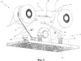
На фиг.3 показан второй общий вид блока для передвижных консольных ворот по данному изобретению, с удалением некоторых элементов для того, чтобы можно было лучше видеть другие элементы;Figure 3 shows a second General view of the block for a mobile cantilever gate according to this invention, with the removal of some elements in order to better see other elements;
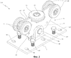
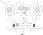
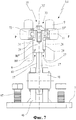
На фиг.4 показан аксонометрический вид сбоку блока для передвижных консольных ворот по данному изобретению;Figure 4 shows a perspective view of a side block for a mobile cantilever gate according to this invention;
На фиг.5 показан аксонометрический вид сверху блока для передвижных консольных ворот по данному изобретению;Figure 5 shows a perspective view from above of a block for a mobile cantilever gate according to this invention;
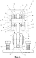
На фиг.6 показан вид блока для передвижных консольных ворот по данному изобретению, в разрезе вдоль линии VI-VI, изображенной на фиг.4, с указанием пунктирной линией направляющей рельсы, уже зафиксированной на воротах.FIG. 6 is a sectional view of the cantilever gate unit of the present invention, in section along the line VI-VI shown in FIG. 4, with a dashed line of the guide rail already fixed to the gate.
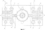
На фиг.7 приводится изображение блока для передвижных консольных ворот по данному изобретению, в разрезе вдоль линии VII-VIII, изображенной на фиг.4.In Fig.7 shows a block image for a mobile cantilever gate according to this invention, in section along the line VII-VIII depicted in Fig.4.
ПОДРОБНОЕ ОПИСАНИЕ ПРЕИМУЩЕСТВЕННЫХ ВАРИАНТОВ ОСУЩЕСТВЛЕНИЯ ИЗОБРЕТЕНИЯDETAILED DESCRIPTION OF THE PREFERRED EMBODIMENTS
Что касается графических материалов, под номером 1 приводится пример установки передвижных консольных ворот, которые поддерживаются двумя опорными блоками 3, 4 по данному изобретению, на их нижней части.As for graphic materials, number 1 gives an example of installing a mobile cantilever gate, which is supported by two support blocks 3, 4 according to this invention, on their lower part.
Термин "ворота" в рамках защиты прав настоящего изобретения включает все возможные ворота, например основные внешние двери или ворота, которые перемещаются из положения открытия в положение закрытия и наоборот, выполняя традиционную функцию регулирования возможности проезда транспортных средств или прохода пешеходов к любому имуществу, строительной площадке, компании, зданию или саду.The term "gate" in the framework of protecting the rights of the present invention includes all possible gates, for example, main external doors or gates that move from the open position to the closed position and vice versa, performing the traditional function of regulating the possibility of vehicles or pedestrians to any property, construction site , company, building or garden.
В соответствии с прилагаемыми графическими материалами ворота 1 имеют несущий каркас 2, который в целом выполнен из стали и который преимущественно выступает вдоль направления движения Х ворот 1. Этот несущий каркас 2 образован металлической рамой, то есть определенным количеством стоек и перекладин. Он обычно оборудуется окрашенными панелями или решетками.In accordance with the accompanying graphic materials, the gate 1 has a supporting frame 2, which is generally made of steel and which mainly protrudes along the direction of movement X of the gate 1. This supporting frame 2 is formed by a metal frame, that is, a certain number of racks and crossbars. It is usually equipped with painted panels or grilles.
Ворота 1 опираются с возможностью движения в двух положениях - открытия и закрытия в направлении движения Х - на два блока 3 и 4, которые расположены на определенном расстоянии один от другого и в целом установлены ровно относительно вышеупомянутого направления движения X.The gate 1 is supported with the possibility of movement in two positions - opening and closing in the direction of movement X - on two blocks 3 and 4, which are located at a certain distance from one another and are generally installed exactly relative to the aforementioned direction of movement X.
Оба блока 3, 4 расположены вне габаритов проходного отверстия и размещены на определенном расстоянии один от другого, что и позволяет им обеспечивать консольную поддержку ворот 1 традиционным способом: один блок обеспечивает тягу, а другой - опору, в зависимости от того, в каком положении находятся ворота 1 - открытом или закрытом.Both blocks 3, 4 are located outside the dimensions of the passage opening and are placed at a certain distance from each other, which allows them to provide console support for the gate 1 in the traditional way: one block provides traction and the other supports, depending on the position in which gate 1 - open or closed.
Чтобы выдержать механические нагрузки, которые передаются воротами 1, каждый из блоков 3, 4 жестко закреплен на поверхности земли с помощью собственной опоры.To withstand the mechanical loads that are transmitted by the gates 1, each of the blocks 3, 4 is rigidly fixed to the ground using its own support.
Также обычно устанавливают средства (не показанные здесь) для передвижения ворот 1 вдоль направления движения X, которые обычно включают зубчатый рельс с креплением к каркасу 2 ворот 1 и закрепленный двигатель в стояке рядом с воротами, который соединяется с помощью шестерни с зубчатым рельсом для обеспечения движения ворот 1.Means are also usually installed (not shown here) for moving the gate 1 along the direction of travel X, which typically include a toothed rail mounted to the carcass 2 of the gate 1 and a fixed motor in a riser near the gate, which is connected by a gear to the toothed rail to allow movement gate 1.
На нижней части ворот 1 с помощью сварки, механического соединения и/или крепежных винтов крепится рельс 5. Этот рельс размещается, в целом, по всей длине ворот 1 и формирует вытянутый полый профиль, внутри которого устанавливаются несколько колес без самостоятельного привода, как будет показано дальше. Эти колеса без самостоятельного привода в состоянии направлять ворота 1 вдоль направления движения Х между положениями открытия и закрытия.A
Следует отметить, что каждый блок 3, 4 содержит опорную конструкцию 6, образованную опорной основой 7, которая должна крепиться к фундаменту в земле (например, с помощью анкерных креплений, устанавливаемых в отверстии 95 опорной основы 7), и несущим элементом 8, который должен крепиться к опорной основе 7, на которую приходится вес ворот 1. На опорной основе 7 могут также устанавливаться регулировочные болты 97 по высоте блоков 3, 4.It should be noted that each block 3, 4 contains a supporting
Соединение между опорной основой 7, включающей металлическую пластину, и несущей стенкой 8 осуществляется, как показано на фигуре, с помощью двух параллельных плоскостей 90, проходящих вертикально от опорной основы, и которые крепятся главным образом путем сваривания 96 и поддерживают вдоль горизонтальной оси 91 несущую стенку 8.The connection between the supporting
Вышеупомянутая несущая стенка 8 элемента конструкции 6 блоков 3, 4 имеет две пары опорных колес 9, 10, установленные с возможностью вращения (в предпочтительном варианте используются две пары опорных колес, но речь может идти об одной или трех парах) и способные, в целом, свободно вращаться на горизонтальной оси в рельсе 5, а также направляющее колесо 11, которое, в целом, может свободно вращаться на вертикальной оси в рельсе 5.The aforementioned bearing wall 8 of the
С функциональной точки зрения две пары опорных колес 9, 10 принимают на себя вес ворот 1 и должны вращаться в рельсе 2, чтобы предоставить воротам 1 возможность двигаться, а направляющее колесо 11 взаимодействует с рельсом, чтобы не допустить отклонений отмеченных ворот 1 перпендикулярно направлению движения X.From a functional point of view, two pairs of
Для этого, как можно видеть на фиг.6, полый профиль рельса 5 (обозначенный пунктирной линией) имеет трубчатую форму, открывается снизу продольной прорезью 12 и имеет противоположно расположенные поперечные и вертикальные, в целом, стенки 13, на которые опирается направляющее колесо 11, а также горизонтальные, в целом, верхнюю 14 и нижнюю 15 противоположные стенки, на которые опираются отмеченные две пары опорных колес 9, 10.For this, as can be seen in Fig.6, the hollow profile of the rail 5 (indicated by a dashed line) has a tubular shape, opens from below by a
В соответствии с идеей, лежащей в основе настоящего изобретения, несущая стенка 8 опорной конструкции 6 содержит, по меньшей мере, две профилированные пластины 17, 17', жестко и параллельно соединенные между собой с помощью средств фиксации 20.In accordance with the idea underlying the present invention, the supporting wall 8 of the supporting
Указанные средства фиксации 20 включают заклепки, винты или шайбы, что позволяет избежать при соединении двух профилированных пластин 17, 17' сварки и, соответственно, сократить время технологического процесса.These fixing means 20 include rivets, screws or washers, which avoids welding when connecting two profiled
Следует отметить, что каждая из профилированных пластин 17, 17' имеет два первых сквозных отверстия 21, совмещенных с соответствующими первыми отверстиями 21', другой профилированной пластины 17', 17 таким образом, что они вместе образовывают два первых гнезда 23, приспособленных для размещения первых опорных элементов 24 для поддержки двух пар опорных колес 9, 10.It should be noted that each of the profiled
Каждая из несущих пластин 17, 17' имеет также углубление 25, совмещенное с соответствующим углублением на другой несущей стенке 17', 17 таким образом, что они вместе образуют второе гнездо 26 для размещения направляющего колеса 11, которое, в свою очередь, опирается с возможностью вращения на второй опорный элемент 27.Each of the
Кроме того, на каждой профилированной пластине 17, 17' имеется выпуклость 28 от верхнего профиля профилированной пластины, которая соответствует вогнутости 25, имеет углубление и направлена в сторону другой профилированной пластины 17, 17'. Вместе они образуют полость 29, связанную, по меньшей мере, частично, со вторыми опорными элементами 27 направляющего колеса 11 и вторым гнездом 26.In addition, on each profiled
Указанная выше выпуклость 28 имеет преимущественно полуцилиндрическую форму, получаемую путем штамповки.The
Как видно из фиг.7, указанные вторые опорные элементы 27 имеют, по меньшей мере, одну первую прокладку 34 с соответствующими отверстиями, установленную во второе гнездо 26 над верхним профилем профилированных плит 17, 17', чтобы удерживать внутреннее кольцо подшипника 72, на внешнем кольце которого установлено упомянутое направляющее колесо 11.As can be seen from Fig.7, these
Полость 29 проходит вертикально вниз и заканчивается в третьем гнезде 30, образуемом вторыми отверстиями 31, выполненными совмещением с двух профилированных пластин 17, 17'. На фиг.3 показана профилированная пластина 17 со стойкой 80, установленной в полость 29 с верхней частью 80' во втором отверстии 31 профилированной пластины 17'.The
Вторые опоры 27 имеют стойку 80 с широкой верхней частью 80', установленную в указанном выше третьем гнезде 32, и хвостовик 80′′, полностью нарезной, установленный в полости 29. Кроме того, указанные вторые опорные элементы 27 имеют стопорный винт 33 с головкой 33', который упирается на внутреннее кольцо подшипника 72, и хвостовик 33′′, который находится в зацеплении с резьбой хвостовика 80′′ стойки 80.The
Таким образом, подшипник 72, опирающийся на направляющее колесо 11, удерживается в указанном втором гнезде 26 внутренним кольцом, зафиксированным между головкой 33′ стопорного винта 33 и распоркой 34.Thus, the
Широкая верхняя часть 80′ стойки 80 имеет прямоугольную форму и соединена с третьим гнездом 30 таким образом, чтобы не давать стойке 80 вращаться вокруг ее оси.The wide
Как правило, ширина третьего гнезда 30 не позволяет вращаться верхней части стойки коммерческих размеров.As a rule, the width of the
Первые опорные элементы 24, поддерживающие две пары опорных колес 9, 10, имеют центральную стойку 37, установленную в соответствующем гнезде 23 с помощью подшипников 50 на две пары опорных колес 9, 10.The
Между первыми отверстиями 21 профилированных плит 17, 17' и подшипниками 50 установлены вторые и третьи распорки 51, 52.Between the
Преимуществом является то, что, по меньшей мере, одна (9) из двух пар опорных колес 9, 10 может регулироваться по высоте для того, чтобы можно было контролировать часть ворот 1, находящихся в закрытом положении.An advantage is that at least one (9) of the two pairs of
Для этого несущий элемент 8 удерживается над плоскостью 90 на опорной основе 7. Под несущим элементом 8 установлен винт 92, который находится в резьбовом отверстии опорной основы 7. Винт 92 устанавливается на нижнюю поверхность профиля 8′′ несущего элемента 8 и может завинчиваться или развинчиваться для того, чтобы менять наклон несущего элемента 8, а также высоту соответствующей пары опорных колес 9. Заданная высота поддерживается также опорной основой 7 с контргайкой 93.For this, the carrier 8 is held above the
Следует отметить, что опорная основа 7 может быть выполнена с помощью изгиба, как правило, горизонтального, на каждой профилированной пластине 17, 17', образуя несущий элемент, направленный в противоположную сторону от изгиба другой профилированной пластины 17', 17.It should be noted that the
В последнем случае регулирование наклона блока 1 может осуществляться в основном так, как указано в заявке ЕР-А-08425418.4, которая приводится для ссылки, на странице 8, строка 22, на странице 9, строка 18, и на фигуре 10.In the latter case, the tilt adjustment of the block 1 can be carried out mainly as described in the application EP-A-08425418.4, which is given for reference, on page 8, line 22, on
Несущий элемент 8 представляет интерес исключительно с точки зрения более высоких механических нагрузок на основание 7. Тем не менее, для того чтобы определить толщину профилированных плит с учетом механического сопротивления для несущего элемента 8, необходимы дополнительные расчеты. В данном случае предпочтительно установить между двумя профилированными пластинами 17, 17' усиливающий несущий элемент (не показан), состоящий из внешнего профиля, подобного тому, который имеет две профилированные пластины 17, 17', с отверстиями 21, 31 внутри, полость 25 в соответствии с отверстиями 21, 31 и полость 25 двух профилированных пластин 17, 17'. При этом не должны вноситься изменения в рабочие характеристики.The carrier element 8 is of interest solely from the point of view of higher mechanical loads on the
Преимуществом является то, что ось вращения Х опорных колес 9, 10 расположена выше средней плоскости точки Р направляющего колеса 11.The advantage is that the axis of rotation X of the
Предметом данного изобретения является также процесс изготовления блока 3, 4 для консольных ворот 1, в частности, указанного выше типа, отличающихся простой использования.The subject of this invention is also the manufacturing process of a block 3, 4 for cantilever gates 1, in particular of the type indicated above, characterized by simple use.
В соответствии с изобретением способ включает этап нарезки профиля из металлического листа, обычно стального, например, путем отрезания или лазерной резки для того, чтобы получить, по меньшей мере, две плоские профилированные пластины 17, 17' с первыми отверстиями 21, вторыми отверстиями 31 и полостью 25, о которых говорилось выше.In accordance with the invention, the method includes the step of cutting a profile of a metal sheet, usually steel, for example, by cutting or laser cutting in order to obtain at least two flat profiled
Кроме того, предусмотрен этап штамповки, в ходе которого с помощью пресса на профилированных пластинах 17, 17' изготавливаются выпуклости, соответствующие полости 29.In addition, a stamping step is provided during which convexes corresponding to the
После нарезки профилированные пластины 17, 17' механически соединяются между собой на этапе фиксации. При этом для изготовления несущего элемента 8 должны быть подготовлены соответствующие отверстия 21, 31 и полость 25.After cutting, the profiled
Несущий элемент 8 жестко крепится к опорной основе 7 на этапе сборки, подробное описание которого приводится ниже. С этого момента можно приступать к установке на несущем элементе 8 двух пар опорных колес 9, 10 и направляющего колеса 11 соответственно с помощью предназначенных для этого первых и вторых опорных элементов 24, 27, установленных в первые гнезда 23 и во второе гнездо 26.The supporting element 8 is rigidly attached to the
Кроме того, этап формовки включает жесткое крепление опорной основы 7 к несущему элементу 8 путем приваривания на опорной пластине, а также параллельную установку пары металлических плоскостей 90 и соединение несущего элемента 8 на горизонтальной стойке 91, установленной на концах указанной выше пары плоскостей 90.In addition, the molding step includes rigidly attaching the
В ходе указанного выше этапа жесткое соединение опорной основы 7 к несущему элементу 8 с помощью прямоугольного изгиба металлического листа, предназначенного для формирования профилированных пластин 17, 17' и формирования, таким образом, части основы, которая будет установлена на этапе фиксации профилированных пластин 17, 17' в направлении, противоположном направлению части основы другой профилированной пластины 8.During the aforementioned step, the rigid connection of the
В данном случае регулировка наклона блока 3, 4 может осуществляться, как указано в заявке ЕР-А-08425418.4, которая приводится для ссылки, страница 8, строка 22, страница 9, строка 18 и фиг.10.In this case, the adjustment of the inclination of the block 3, 4 can be carried out, as indicated in the application EP-A-08425418.4, which is given for reference, page 8, line 22,
Путем выполнения указанных действий возможно достижение установленных целей.By performing these actions, it is possible to achieve the established goals.
При практическом изготовлении могут использоваться также другие формы и конфигурации, отличающиеся от указанных выше без выхода за пределы объема защиты.In practical manufacturing, other shapes and configurations may also be used that differ from those indicated above without going beyond the scope of protection.
Следует отметить, что все детали могут быть заменены эквивалентными с технической точки зрения элементами, а используемые размеры, формы и материалы могут быть любыми в зависимости от потребностей.It should be noted that all parts can be replaced by elements equivalent from a technical point of view, and the sizes, shapes and materials used can be any depending on the needs.
Claims (7)
- опорную конструкцию, которая содержит:
- основание, которое должно крепиться к земле, и
- несущий элемент, который крепится к указанному основанию;
- по меньшей мере, одну пару опорных колес, которые установлены на несущем элементе указанной опорной конструкции и могут свободно вращаться вокруг в целом горизонтальных осей вращения в указанном рельсе для удержания веса указанных ворот;
по меньшей мере, одно направляющее колесо, которое установлено на несущем элементе указанной опорной конструкции и может свободно вращаться вокруг вертикальной, в целом, оси вращения в отмеченном рельсе, во избежание отклонений указанных ворот перпендикулярно направлению их движения;
отличающийся тем, что несущий элемент указанной опорной конструкции формируется, по меньшей мере, двумя профилированными пластинами, жестко и параллельно соединенными между собой с помощью креплений, каждая из которых содержит:
два первых отверстия, совмещенные с соответствующими первыми отверстиями другой профилированной пластины, которые образуют вместе два первых гнезда для размещения первых опорных элементов, и, по меньшей мере, одной пары опорных колес;
вогнутость на верхнем профиле указанной профилированной пластины, совмещенную с подобной вогнутостью другой профилированной пластины, которые образуют вместе второе гнездо для направляющего колеса с возможностью вращения и опорой на вторые опорные элементы;
выпуклость, идущую от верхнего профиля указанной профилированной пластины, соответствующую полости и имеющую углубление, противоположное углублению другой профилированной пластины, которые образуют вместе полость для размещения, по меньшей мере, частичного, вторых опорных элементов указанного направляющего колеса, и для соединения с указанным вторым гнездом.1. The block for a mobile cantilever gate with a supporting frame, placed along the direction of movement of the gate with a hollow rail fixed to its lower part and along the marked direction of movement for the direction of the specified gate, including:
- supporting structure, which contains:
- the base, which should be attached to the ground, and
- a supporting element that is attached to the specified base;
- at least one pair of support wheels that are mounted on the supporting element of the specified supporting structure and can freely rotate around the generally horizontal axes of rotation in the specified rail to hold the weight of the specified gate;
at least one steering wheel, which is mounted on the supporting element of the indicated supporting structure and can freely rotate around the vertical, in general, axis of rotation in the marked rail, in order to avoid deviations of these gates perpendicular to the direction of their movement;
characterized in that the supporting element of the indicated supporting structure is formed by at least two profiled plates rigidly and parallelly interconnected by means of fasteners, each of which contains:
two first holes, combined with the corresponding first holes of another profiled plate, which form together the first two slots for accommodating the first support elements, and at least one pair of support wheels;
concavity on the upper profile of the specified profiled plate, combined with a similar concavity of the other profiled plate, which together form a second slot for the guide wheel with the possibility of rotation and support on the second supporting elements;
a bulge extending from the upper profile of said profiled plate, corresponding to a cavity and having a recess opposite to that of another profiled plate, which together form a cavity for receiving at least partial second support elements of said guide wheel and for connecting to said second socket.
стадия, на котором нарезают профиль толстого листа с целью получения, по меньшей мере, двух плоских пластин определенной формы с выполненными на них отмеченными первыми отверстиями и полостями;
этап штамповки, в ходе которой с помощью пресса на профилированных пластинах изготавливают выпуклости, определяющие полость;
этап, на котором фиксируют указанные профилированные пластины с соответствующими первыми отверстиями и полостью для изготовления указанного несущего элемента;
этап сборки, на котором жестко соединяют указанное основание с указанным несущим элементом;
этап, на котором монтируют отмеченные опорные колеса и указанное направляющее колесо в указанных первых гнездах и во втором гнезде соответственно с помощью указанных первых и вторых опорных элементов.5. A method of manufacturing a block for a mobile cantilever gate according to claim 1, characterized in that it includes the following stages:
the stage at which the profile of the thick sheet is cut in order to obtain at least two flat plates of a certain shape with the first holes and cavities marked on them;
stamping stage, during which using the press on the profiled plates produce bulges defining the cavity;
a step in which the said profiled plates are fixed with the corresponding first holes and a cavity for manufacturing said carrier element;
an assembly step in which said base is rigidly connected to said carrier element;
a step in which the marked support wheels and said guide wheel are mounted in said first slots and in a second slot, respectively, using said first and second support elements.
Applications Claiming Priority (2)
| Application Number | Priority Date | Filing Date | Title |
|---|---|---|---|
| ITPD2009A000107 | 2009-04-23 | ||
| ITPD2009A000107A IT1393733B1 (en) | 2009-04-23 | 2009-04-23 | TROLLEY FOR SLIDING GATE AND THE PROCEDURE FOR ITS REALIZATION |
Publications (2)
| Publication Number | Publication Date |
|---|---|
| RU2010115964A RU2010115964A (en) | 2011-10-27 |
| RU2531741C2 true RU2531741C2 (en) | 2014-10-27 |
Family
ID=41278528
Family Applications (1)
| Application Number | Title | Priority Date | Filing Date |
|---|---|---|---|
| RU2010115964/12A RU2531741C2 (en) | 2009-04-23 | 2010-04-22 | Block for mobile cantilever gate and method of its manufacturing |
Country Status (2)
| Country | Link |
|---|---|
| IT (1) | IT1393733B1 (en) |
| RU (1) | RU2531741C2 (en) |
Cited By (1)
| Publication number | Priority date | Publication date | Assignee | Title |
|---|---|---|---|---|
| IT201800003082A1 (en) * | 2018-02-27 | 2019-08-27 | Comunello Flii Spa | CARRIAGE FOR CANTILEVERED SLIDING GATES |
Citations (3)
| Publication number | Priority date | Publication date | Assignee | Title |
|---|---|---|---|---|
| DE2743007A1 (en) * | 1977-09-23 | 1979-03-29 | Hoermann Kg Antrieb Steuertec | Powered sliding doorway plinth beam - has fittings for optionally shaped blocking devices along its length |
| FR2710945A1 (en) * | 1993-10-06 | 1995-04-14 | Ouest Travaux Generaux | Self-supporting cantilevered sliding gate |
| DE29915745U1 (en) * | 1999-09-08 | 2001-01-11 | Schmid, Peter, 72116 Mössingen | Roller block for supporting a running rail of a sliding gate |
Family Cites Families (1)
| Publication number | Priority date | Publication date | Assignee | Title |
|---|---|---|---|---|
| DE4236962A1 (en) * | 1992-11-02 | 1994-05-05 | Huegle Pfullendorf Kipptor | Cantilever sliding gate |
-
2009
- 2009-04-23 IT ITPD2009A000107A patent/IT1393733B1/en active
-
2010
- 2010-04-22 RU RU2010115964/12A patent/RU2531741C2/en active
Patent Citations (3)
| Publication number | Priority date | Publication date | Assignee | Title |
|---|---|---|---|---|
| DE2743007A1 (en) * | 1977-09-23 | 1979-03-29 | Hoermann Kg Antrieb Steuertec | Powered sliding doorway plinth beam - has fittings for optionally shaped blocking devices along its length |
| FR2710945A1 (en) * | 1993-10-06 | 1995-04-14 | Ouest Travaux Generaux | Self-supporting cantilevered sliding gate |
| DE29915745U1 (en) * | 1999-09-08 | 2001-01-11 | Schmid, Peter, 72116 Mössingen | Roller block for supporting a running rail of a sliding gate |
Cited By (1)
| Publication number | Priority date | Publication date | Assignee | Title |
|---|---|---|---|---|
| IT201800003082A1 (en) * | 2018-02-27 | 2019-08-27 | Comunello Flii Spa | CARRIAGE FOR CANTILEVERED SLIDING GATES |
Also Published As
| Publication number | Publication date |
|---|---|
| ITPD20090107A1 (en) | 2010-10-24 |
| IT1393733B1 (en) | 2012-05-08 |
| RU2010115964A (en) | 2011-10-27 |
Similar Documents
| Publication | Publication Date | Title |
|---|---|---|
| RU2485272C2 (en) | Trolley for sliding supported gates and method of its manufacture | |
| EP2105573A2 (en) | A sliding door arrangement | |
| JP2012517361A (en) | Modular building construction equipment | |
| RU2531741C2 (en) | Block for mobile cantilever gate and method of its manufacturing | |
| CN107816136B (en) | Built-in fitting positioner | |
| KR101590093B1 (en) | Mounting apparatus for open-joint type finishing panel | |
| EP3064112B1 (en) | Locking device and shower room assembly | |
| CN115627832A (en) | Assembled building steel structure connecting piece | |
| CN215442899U (en) | Assembled ground basic unit system | |
| EP3650624B1 (en) | Carriage for a cantilever slidable gate | |
| KR100638804B1 (en) | Structure for supporting window boxing of building | |
| JP7393118B2 (en) | Starter parts, exterior walls, and construction methods for exterior walls | |
| EP2886763A1 (en) | Glass element | |
| CN220365146U (en) | Building steel structure support piece | |
| CN220908849U (en) | Double-T plate beam structure connecting device with stretching and folding functions | |
| CN220766196U (en) | Cage rail at bottom of construction elevator | |
| CN220080298U (en) | Steel structure upright post | |
| CN220767826U (en) | Highway bridge anticollision limit for height compound enhancement formula steel column roof beam | |
| CN220645364U (en) | Post-cast strip strutting arrangement | |
| CZ30697U1 (en) | Construction of an elevator shaft | |
| CN219344101U (en) | Temporary wall supporting device | |
| CN221249393U (en) | Trompil location auxiliary device | |
| CN219632935U (en) | Steel construction welding construction support | |
| JP2012244139A (en) | Solar cell panel installation structure | |
| CN117027243B (en) | Three-dimensional adjustment switching structure and adjustment method for spherical curtain wall unit plate |