RU2530334C2 - Target visual tracking - Google Patents
Target visual tracking Download PDFInfo
- Publication number
- RU2530334C2 RU2530334C2 RU2011132029/08A RU2011132029A RU2530334C2 RU 2530334 C2 RU2530334 C2 RU 2530334C2 RU 2011132029/08 A RU2011132029/08 A RU 2011132029/08A RU 2011132029 A RU2011132029 A RU 2011132029A RU 2530334 C2 RU2530334 C2 RU 2530334C2
- Authority
- RU
- Russia
- Prior art keywords
- model
- depth
- synthesized
- pixel
- observed
- Prior art date
Links
Images
Classifications
-
- G—PHYSICS
- G06—COMPUTING; CALCULATING OR COUNTING
- G06T—IMAGE DATA PROCESSING OR GENERATION, IN GENERAL
- G06T7/00—Image analysis
- G06T7/20—Analysis of motion
- G06T7/246—Analysis of motion using feature-based methods, e.g. the tracking of corners or segments
- G06T7/251—Analysis of motion using feature-based methods, e.g. the tracking of corners or segments involving models
-
- A—HUMAN NECESSITIES
- A63—SPORTS; GAMES; AMUSEMENTS
- A63F—CARD, BOARD, OR ROULETTE GAMES; INDOOR GAMES USING SMALL MOVING PLAYING BODIES; VIDEO GAMES; GAMES NOT OTHERWISE PROVIDED FOR
- A63F13/00—Video games, i.e. games using an electronically generated display having two or more dimensions
- A63F13/20—Input arrangements for video game devices
- A63F13/21—Input arrangements for video game devices characterised by their sensors, purposes or types
- A63F13/213—Input arrangements for video game devices characterised by their sensors, purposes or types comprising photodetecting means, e.g. cameras, photodiodes or infrared cells
-
- A—HUMAN NECESSITIES
- A63—SPORTS; GAMES; AMUSEMENTS
- A63F—CARD, BOARD, OR ROULETTE GAMES; INDOOR GAMES USING SMALL MOVING PLAYING BODIES; VIDEO GAMES; GAMES NOT OTHERWISE PROVIDED FOR
- A63F13/00—Video games, i.e. games using an electronically generated display having two or more dimensions
- A63F13/40—Processing input control signals of video game devices, e.g. signals generated by the player or derived from the environment
- A63F13/42—Processing input control signals of video game devices, e.g. signals generated by the player or derived from the environment by mapping the input signals into game commands, e.g. mapping the displacement of a stylus on a touch screen to the steering angle of a virtual vehicle
- A63F13/428—Processing input control signals of video game devices, e.g. signals generated by the player or derived from the environment by mapping the input signals into game commands, e.g. mapping the displacement of a stylus on a touch screen to the steering angle of a virtual vehicle involving motion or position input signals, e.g. signals representing the rotation of an input controller or a player's arm motions sensed by accelerometers or gyroscopes
-
- A—HUMAN NECESSITIES
- A63—SPORTS; GAMES; AMUSEMENTS
- A63F—CARD, BOARD, OR ROULETTE GAMES; INDOOR GAMES USING SMALL MOVING PLAYING BODIES; VIDEO GAMES; GAMES NOT OTHERWISE PROVIDED FOR
- A63F2300/00—Features of games using an electronically generated display having two or more dimensions, e.g. on a television screen, showing representations related to the game
- A63F2300/10—Features of games using an electronically generated display having two or more dimensions, e.g. on a television screen, showing representations related to the game characterized by input arrangements for converting player-generated signals into game device control signals
- A63F2300/1087—Features of games using an electronically generated display having two or more dimensions, e.g. on a television screen, showing representations related to the game characterized by input arrangements for converting player-generated signals into game device control signals comprising photodetecting means, e.g. a camera
- A63F2300/1093—Features of games using an electronically generated display having two or more dimensions, e.g. on a television screen, showing representations related to the game characterized by input arrangements for converting player-generated signals into game device control signals comprising photodetecting means, e.g. a camera using visible light
-
- A—HUMAN NECESSITIES
- A63—SPORTS; GAMES; AMUSEMENTS
- A63F—CARD, BOARD, OR ROULETTE GAMES; INDOOR GAMES USING SMALL MOVING PLAYING BODIES; VIDEO GAMES; GAMES NOT OTHERWISE PROVIDED FOR
- A63F2300/00—Features of games using an electronically generated display having two or more dimensions, e.g. on a television screen, showing representations related to the game
- A63F2300/60—Methods for processing data by generating or executing the game program
- A63F2300/66—Methods for processing data by generating or executing the game program for rendering three dimensional images
- A63F2300/6607—Methods for processing data by generating or executing the game program for rendering three dimensional images for animating game characters, e.g. skeleton kinematics
-
- G—PHYSICS
- G06—COMPUTING; CALCULATING OR COUNTING
- G06T—IMAGE DATA PROCESSING OR GENERATION, IN GENERAL
- G06T2207/00—Indexing scheme for image analysis or image enhancement
- G06T2207/10—Image acquisition modality
- G06T2207/10016—Video; Image sequence
- G06T2207/10021—Stereoscopic video; Stereoscopic image sequence
-
- G—PHYSICS
- G06—COMPUTING; CALCULATING OR COUNTING
- G06T—IMAGE DATA PROCESSING OR GENERATION, IN GENERAL
- G06T2207/00—Indexing scheme for image analysis or image enhancement
- G06T2207/10—Image acquisition modality
- G06T2207/10028—Range image; Depth image; 3D point clouds
-
- G—PHYSICS
- G06—COMPUTING; CALCULATING OR COUNTING
- G06T—IMAGE DATA PROCESSING OR GENERATION, IN GENERAL
- G06T2207/00—Indexing scheme for image analysis or image enhancement
- G06T2207/30—Subject of image; Context of image processing
- G06T2207/30196—Human being; Person
Abstract
Description
Уровень техникиState of the art
Многие компьютерные игры и другие компьютерные видеопрограммы используют сложные управляющие действия, чтобы дать возможность пользователям управлять игровыми персонажами или другими аспектами прикладной программы. Такие управляющие действия могут быть сложными для изучения и тем самым создают барьер для доступа ко многим играм и другим прикладным программам. Кроме того, такие управляющие действия могут сильно отличаться от фактических игровых действий или других действий прикладной программы, для которых они используются. Например, игровое управляющее действие, которое заставляет игрового персонажа размахнуться бейсбольной битой, может быть не похоже на фактическое движение размаха бейсбольной битой.Many computer games and other computer video programs use complex control actions to enable users to control game characters or other aspects of the application program. Such control actions can be difficult to learn and thereby create a barrier to access to many games and other applications. In addition, such control actions can be very different from the actual game actions or other actions of the application for which they are used. For example, a game control action that causes a game character to swing a baseball bat may not look like the actual movement of the swing with a baseball bat.
СУЩНОСТЬ ИЗОБРЕТЕНИЯSUMMARY OF THE INVENTION
Это описание сущности изобретения предоставлено для того, чтобы в упрощенной форме представить подборку концепций, которые далее описаны в подробном описании. Это описание сущности изобретения не предназначено для выявления ключевых признаков или основных признаков заявленного изобретения, а также не предназначено для использования в качестве ограничения объема заявленного изобретения. Кроме того, заявленное изобретение не ограничено реализациями, которые устраняют какие-либо или все из недостатков, отмеченных в любой части этого раскрытия.This description of the invention is provided in order to simplify the presentation of a selection of concepts, which are further described in the detailed description. This description of the invention is not intended to identify key features or main features of the claimed invention, nor is it intended to be used as a limitation on the scope of the claimed invention. In addition, the claimed invention is not limited to implementations that eliminate any or all of the disadvantages noted in any part of this disclosure.
В данном документе рассматриваются различные варианты воплощения, относящиеся к визуальному отслеживанию цели. Один раскрытый вариант воплощения включает в себя отслеживание цели посредством приема от источника наблюдаемого изображения цели с глубиной и получения находящейся в позе модели цели. Находящаяся в позе модель растеризуется в синтезированное изображение с глубиной. Затем поза модели корректируется, по меньшей мере частично, на основе различий между наблюдаемым изображением с глубиной и синтезированным изображением с глубиной.This document discusses various embodiments related to visual tracking of a target. One disclosed embodiment includes tracking a target by receiving a target with depth from a source of the observed image and acquiring a target model. The model in the pose is rasterized into a synthesized image with depth. The model posture is then corrected, at least in part, based on the differences between the observed image with depth and the synthesized image with depth.
КРАТКОЕ ОПИСАНИЕ ЧЕРТЕЖЕЙBRIEF DESCRIPTION OF THE DRAWINGS
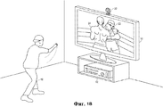
Фиг.1А показывает вариант воплощения иллюстративной системы распознавания, анализа и отслеживания цели, отслеживающей игрока, играющего в игру с имитацией бокса.1A shows an embodiment of an illustrative target recognition, analysis, and tracking system tracking a player playing a simulated boxing game.
Фиг.1В показывает игрока, показанного на фиг.1А, наносящего удар, который отслеживается и интерпретируется как игровое управляющее действие, которое заставляет видеообраз проигрывателя нанести удар в игровом пространстве.FIG. 1B shows the player of FIG. 1A, striking, which is tracked and interpreted as a game control action that causes the video image of the player to strike in the playing space.
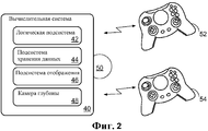
Фиг.2 схематично показывает вычислительную систему в соответствии с вариантом воплощения настоящего раскрытия.Figure 2 schematically shows a computing system in accordance with an embodiment of the present disclosure.
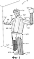
Фиг.3 показывает иллюстративную модель тела, используемую для представления цели-человека.Figure 3 shows an illustrative model of the body used to represent the human target.
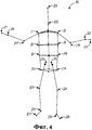
Фиг.4 показывает в значительной степени вид спереди иллюстративной скелетной модели, используемой для представления цели-человека.Figure 4 shows a large extent front view of an illustrative skeletal model used to represent a human target.
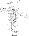
Фиг.5 показывает вид под углом иллюстративной скелетной модели, используемой для представления цели-человека.5 shows an angled view of an illustrative skeletal model used to represent a human target.
Фиг.6 показывает иллюстративную сеточную модель, используемую для представления цели-человека.6 shows an illustrative grid model used to represent a human target.
Фиг.7 показывает блок-схему последовательности операций иллюстративного способа визуального отслеживания цели.7 shows a flowchart of an illustrative method for visually tracking a target.
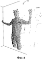
Фиг.8 показывает иллюстративное наблюдаемое изображение с глубиной.8 shows an illustrative observed image with depth.
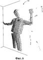
Фиг.9 показывает иллюстративное синтезированное изображение с глубиной.Fig.9 shows an illustrative synthesized image with depth.
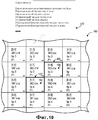
Фиг.10 схематично показывает некоторые из пикселей, составляющих синтезированное изображение с глубиной.10 schematically shows some of the pixels constituting a synthesized image with depth.
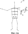
Фиг.11А схематично показывает приложение силы к месту приема силы модели.11A schematically shows the application of force to the place of reception of the force of the model.
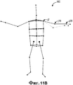
Фиг.11В схематично показывает результат приложения силы к месту приема силы модели, показанной на фиг.11А.FIG. 11B schematically shows the result of applying force to the power receiving location of the model shown in FIG. 11A.
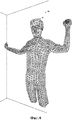
Фиг.12А показывает видеообраз игрока, реализованный из модели на фиг.11А.12A shows a video image of a player implemented from the model of FIG. 11A.
Фиг.12В показывает видеообраз игрока, реализованный из модели на фиг.11В.12B shows a video image of a player implemented from the model of FIG. 11B.
ПОДРОБНОЕ ОПИСАНИЕDETAILED DESCRIPTION
Настоящее раскрытие направлено на распознавание, анализ и отслеживание цели. В частности, раскрыто использование камеры глубины или другого источника для получения информации глубины для одной или более целей. Такая информация глубины затем может быть использована для эффективного и точного моделирования и отслеживания одной или более целей, как описано подробно ниже. Описанные в данном документе распознавание, анализ и отслеживание цели обеспечивают устойчивую платформу, в которой одна или более целей могут быть согласованно отслежены при относительно высокой частоте кадров, даже когда цель (цели) принимает позы, которые считаются трудными для анализа с использованием других подходов (например, когда две или более целей частично накладываются и/или закрывают друг друга; когда часть цели закрывает другую часть той же самой цели, когда цель изменяет свою топологию (например, человек, касающийся своей головы) и т.д.).The present disclosure is directed to target recognition, analysis and tracking. In particular, the use of a depth camera or other source to obtain depth information for one or more purposes is disclosed. Such depth information can then be used to efficiently and accurately model and track one or more targets, as described in detail below. Target recognition, analysis, and tracking described in this document provide a sustainable platform in which one or more goals can be consistently tracked at a relatively high frame rate, even when the target (s) accepts poses that are considered difficult to analyze using other approaches (e.g. when two or more goals partially overlap and / or close each other; when part of the goal covers another part of the same goal, when the goal changes its topology (for example, a person touching his r catches), etc.).
Фиг.1А показывает неограничивающий пример системы 10 распознавания, анализа и отслеживания цели. В частности, фиг.1А показывает игровую компьютерную систему 12, которая может использоваться для игры во множество различных игр, воспроизведения одного или более различных видов носителей информации и/или управления или манипулирования не игровыми прикладными программами. Фиг.1А также показывает дисплей 14 в виде телевизора 16 с высоким разрешением или HDTV, который может использоваться для представления игрокам, таким как игрок 18, визуальной информации игры. Кроме того, фиг.1А показывает устройство захвата в виде камеры 20 глубины, которое может использоваться для визуального отслеживания одного или более игроков, таких как игрок 18. Пример, показанный на фиг.1А, является не ограничивающим. Как описано ниже со ссылкой на фиг.2, множество систем распознавания, анализа и отслеживания цели различных типов может использоваться без отступления от объема этого раскрытия.1A shows a non-limiting example of a target recognition, analysis, and tracking system 10. In particular, FIG. 1A shows a
Система распознавания, анализа и отслеживания цели может использоваться для распознавания, анализа и/или отслеживания одной или более целей, таких как игрок 18. Фиг.1А показывает сценарий, в котором игрок 18 отслеживается с использованием камеры 20 глубины таким образом, что движения игрока 18 могут быть интерпретированы игровой системой 12 как управляющие действия, которые могут использоваться для воздействия на игру, исполняемую игровой системой 12. Другими словами, игрок 18 может использовать свои движения для управления игрой. Движения игрока 18 могут быть интерпретированы в качестве игрового управляющего действия фактически любого типа.A target recognition, analysis and tracking system can be used to recognize, analyze and / or track one or more targets, such as
Иллюстративный сценарий, изображенный на фиг.1А, показывает игрока 18, играющего в игру с имитацией бокса, которая исполняется игровой системой 12. Игровая система использует телевизор 16 HDTV для визуального представления боксирующего противника 22 игроку 18. Кроме того, игровая система использует телевизор 16 HDTV для визуального представления видеообраза 24 игрока, которым игрок 18 управляет с помощью своих движений. Как показано на фиг.1В, игрок 18 может нанести удар в физическом пространстве в качестве команды, чтобы видеообраз 24 игрока нанес удар в игровом пространстве. Игровая система 12 и камера 20 глубины могут использоваться для распознавания и анализа удара игрока 18 в физическом пространстве таким образом, чтобы удар мог быть интерпретирован как игровое управляющее движение, которое заставляет видеообраз 24 игрока нанести удар в игровом пространстве. Например, фиг.1В показывает телевизор 16 HDTV, визуально представляющий видеообраз 24 игрока, наносящий удар, который попадает в боксирующего противника 22, в ответ на нанесение удара игроком 18 в физическом пространстве.The illustrative scenario depicted in FIG. 1A shows a
Другие движения игрока 18 могут быть интерпретированы как другие управляющие действия, такие как управляющие действия для подскока, покачивания, уклона, блока, удара по корпусу или нанесения различных по мощности ударов. Кроме того, некоторые движения могут быть интерпретированы как управляющие действия, которые служат целям, отличающимся от управления видеообразом 24 игрока. Например, игрок может использовать движения для завершения, приостановки или сохранения игры, выбора уровня, просмотра таблицы рекордов, общения с другом и т.д.Other movements of the
В некоторых вариантах воплощения цель может включать в себя человека и объект. В таких вариантах воплощения, например, игрок в электронную игру может держать объект, таким образом, движения игрока и объекта могут использоваться для корректировки и/или управления параметрами электронной игры. Например, движение игрока, держащего ракетку, может быть отслежено и использовано для управления экранной ракеткой в электронной спортивной игре. В другом примере движение игрока, держащего объект, может быть отслежено и использовано для управления экранным оружием в электронной боевой игре.In some embodiments, the goal may include a person and an object. In such embodiments, for example, the player in the electronic game can hold the object, so the movements of the player and the object can be used to adjust and / or control the parameters of the electronic game. For example, the movement of a player holding a racket can be tracked and used to control a screen racket in an electronic sports game. In another example, the movement of a player holding an object can be tracked and used to control on-screen weapons in an electronic combat game.
Системы распознавания, анализа и отслеживания цели могут использоваться для интерпретации движений цели в качестве управляющих действий операционной системы и/или прикладной программы, которые находятся вне области игр. Фактически любым управляемым аспектом операционной системы и/или прикладной программы, такой как игра с имитацией бокса, показанная на фиг.1А и 1В, можно управлять посредством движения цели, такой как игрок 18. Проиллюстрированный сценарий с имитацией бокса предоставлен в качестве примера, но не предназначен для какого-либо ограничения. Напротив, проиллюстрированный сценарий предназначен для демонстрации общей концепции, которая может быть применена ко множеству различных прикладных программ без отступления от контекста этого раскрытия.Target recognition, analysis and tracking systems can be used to interpret target movements as control actions of the operating system and / or application program that are outside the field of games. In fact, any controllable aspect of the operating system and / or application program, such as the box simulation game shown in FIGS. 1A and 1B, can be controlled by moving a target, such as
Описанные в данном документе способы и процессы могут быть привязаны к множеству вычислительных систем различных типов. Фиг.1А и 1В показывают не ограничивающий пример в виде игровой системы 12, телевизора 16 HDTV и камеры 20 глубины. В качестве другого, более общего примера фиг.2 схематично показывает вычислительную систему 40, которая может выполнять один или более описанных в данном документе способов и процессов распознавания, отслеживания и анализа цели. Вычислительная система 40 может принимать множество различных видов, в том числе среди других систем, но без ограничения, игровых консолей, игровых систем на основе персонального компьютера, военных систем отслеживания и/или наведения на цель и систем опознавания персонажей с “зеленым экраном” или захватом движения.The methods and processes described herein may be associated with a variety of computing systems of various types. 1A and 1B show a non-limiting example in the form of a
Вычислительная система 40 может включать в себя логическую подсистему 42, подсистему 44 хранения данных, подсистему 46 отображения и/или устройство 48 захвата. Вычислительная система может факультативно включать в себя компоненты, которые не показаны на фиг.2, и/или некоторые компоненты, которые показаны на фиг.2, могут являться периферийными компонентами, которые не интегрированы в вычислительную систему.
Логическая подсистема 42 может включать в себя одно или более физических устройств, выполненных с возможностью исполнять одну или более команд. Например, логическая подсистема может быть выполнена с возможностью исполнять одну или более команд, которые являются частью одной или более программ, подпрограмм, объектов, компонентов, структур данных или других логических конструкций. Такие команды могут быть реализованы для выполнения задачи, реализации типа данных, преобразования состояния одного или более устройств или иного достижения желаемого результата. Логическая подсистема может включать в себя один или более процессоров, которые выполнены с возможностью исполнять программные команды. Дополнительно или в качестве альтернативы логическая подсистема может включать в себя одну или более аппаратных или программно-аппаратных логических машин, выполненных с возможностью исполнять аппаратные или программно-аппаратные команды. Логическая подсистема может факультативно включать в себя индивидуальные компоненты, которые распределены по двум или более устройствам, которые в некоторых вариантах воплощения могут быть расположены удаленно.
Подсистема 44 хранения данных может включать в себя одно или более физических устройств, выполненных с возможностью хранить данные и/или команды, исполнимые посредством логической подсистемы, для реализации описанных в данном документе способов и процессов. Когда такие способы и процессы реализуются, состояние подсистемы 44 хранения данных может быть преобразовано (например, для хранения разных данных). Подсистема 44 хранения данных может включать в себя сменные носители и/или встроенные устройства. Подсистема 44 хранения данных может включать в себя среди других оптические запоминающие устройства, полупроводниковые запоминающие устройства (например, оперативное запоминающее устройство (RAM; ОЗУ), электрически стираемое программируемое постоянное запоминающее устройство (EEPROM; ЭСППЗУ), перепрограммируемое устройство и т.д.) и/или магнитные запоминающие устройства. Подсистема 44 хранения данных может включать в себя устройства с одной или более из следующих характеристик: энергозависимые, энергонезависимые, динамические, статические, для чтения/записи, только для чтения, с произвольным доступом, с последовательным доступом, с адресацией по местоположению, с файловой адресацией и ассоциативные. В некоторых вариантах воплощения логическая подсистема 42 и подсистема 44 хранения данных могут быть интегрированы в одно или более общих устройств, таких как специализированная интегральная схема или система на микросхеме.The data storage subsystem 44 may include one or more physical devices configured to store data and / or instructions executable by a logical subsystem to implement the methods and processes described herein. When such methods and processes are implemented, the state of the data storage subsystem 44 may be transformed (for example, to store different data). The storage subsystem 44 may include removable media and / or embedded devices. The storage subsystem 44 may include, among others, optical storage devices, semiconductor storage devices (e.g., random access memory (RAM; RAM), electrically erasable programmable read-only memory (EEPROM; EEPROM), reprogrammable device, etc.) and / or magnetic storage devices. Storage subsystem 44 may include devices with one or more of the following characteristics: volatile, non-volatile, dynamic, static, read / write, read-only, random access, sequential access, location-based addressing, file-addressing and associative. In some embodiments, the
Фиг.2 также показывает аспект подсистемы хранения данных в виде машиночитаемых сменных носителей 50, которые могут использоваться для хранения и/или передачи данных и/или исполняемых команд для реализации описанных в данном документе способов и процессов.Figure 2 also shows an aspect of a data storage subsystem in the form of computer-readable
Подсистема 46 отображения может использоваться для визуального представления данных, хранимых подсистемой 44 хранения данных. По мере того как описанные в данном документе способы и процессы изменяют данные, хранимые подсистемой хранения данных, и тем самым преобразовывают состояние подсистемы хранения данных, состояние подсистемы 46 отображения может быть аналогичным образом преобразовано для визуального представления изменений в лежащих в основе данных. В качестве не ограничивающего примера описанные в данном документе распознавание, отслеживание и анализ могут быть отражены через подсистему 46 отображения в виде игрового персонажа, который изменяет позы в игровом пространстве в ответ на движения игрока в физическом пространстве. Подсистема 46 отображения может включать в себя одно или более устройств отображения, использующих технологию практически любого типа. Такие устройства отображения могут быть объединены с логической подсистемой 42 и/или подсистемой 44 хранения данных в совместно используемом корпусе, или такие устройства отображения могут являться периферийными устройствами отображения, как показано на фиг.1А и 1В.The
Вычислительная система 40 дополнительно включает в себя устройство 48 захвата, выполненное с возможностью получать изображения с глубиной для одной или более целей. Устройство 48 захвата может быть выполнено с возможностью захватывать видеоинформацию с информацией глубины через любую подходящую методику (например, время прохождения, структурированное освещение, стереоскопическое изображение и т.д.). Таким образом, устройство 48 захвата может включать в себя камеру глубины, видеокамеру, стереоскопические камеры и/или другие подходящие устройства захвата.
Например, при анализе по методике времени прохождения устройство 48 захвата может испускать инфракрасный свет к цели и затем может использовать датчики для обнаружения света, отраженного от поверхности цели. В некоторых случаях может использоваться импульсный инфракрасный свет, причем время между исходящим световым импульсом и соответствующим входящим световым импульсом может быть измерено и использовано для определения физического расстояния от устройства захвата до конкретного местоположения на цели. В некоторых случаях фаза исходящей световой волны может быть сравнена с фазой входящей световой волны для определения сдвига фазы, и сдвиг фазы может быть использован для определения физического расстояния от устройства захвата до конкретного местоположения на цели.For example, when analyzing the transit time technique, the
В другом примере анализ по методике времени прохождения может использоваться для косвенного определения физического расстояния от устройства захвата до конкретного местоположения на цели посредством анализа интенсивности отраженного луча света в течение времени посредством таких методик, как формирование изображений с помощью прерывистых световых импульсов.In another example, transit time analysis can be used to indirectly determine the physical distance from the capture device to a specific location on a target by analyzing the intensity of the reflected light beam over time using techniques such as imaging using intermittent light pulses.
В другом примере для захвата информации глубины устройством 48 захвата может быть использован анализ с помощью структурированного освещения. При таком анализе структурированный свет (то есть свет, отображаемый с известным рисунком, таким как сетчатый рисунок или рисунок в полоску) может быть спроецирован на цель. После столкновения с поверхностью цели рисунок в ответ может стать деформированным, и эта деформация рисунка может быть изучена для определения физического расстояния от устройства захвата до конкретного местоположения на цели.In another example, structured illumination analysis may be used to capture depth information by
В другом примере устройство захвата может включать в себя две или более физически разделенные камеры, которые обозревают цель с различных углов для получения стереоскопических визуальных данных. В таких случаях стереоскопические визуальные данные могут быть проанализированы для формирования информации глубины.In another example, the capture device may include two or more physically separated cameras that view the target from different angles to obtain stereoscopic visual data. In such cases, stereoscopic visual data can be analyzed to generate depth information.
В других вариантах воплощения устройство 48 захвата может использовать другие технологии для измерения и/или вычисления значений глубины. Дополнительно устройство 48 захвата может организовать вычисленную информацию глубины в “уровни по оси Z”, то есть уровни, перпендикулярные по отношению к оси Z, простирающейся от камеры глубины вдоль ее луча обзора к наблюдателю.In other embodiments, the
В некоторых вариантах воплощения две или более разные камеры могут быть включены в интегрированное устройство захвата. Например, камера глубины и видеокамера (например, видеокамера RGB) могут быть включены в общее устройство захвата. В некоторых вариантах воплощения могут совместно использоваться два или более отдельных устройства захвата. Например, могут использоваться камера глубины и отдельная видеокамера. Когда используется видеокамера, она может использоваться для обеспечения данных отслеживания цели, данных подтверждения для коррекции ошибок отслеживания цели, захвата изображения, распознавания лица, отслеживания движения пальцев рук (или других малых признаков) с высокой точностью, светового обнаружения и/или других функций.In some embodiments, two or more different cameras may be included in the integrated capture device. For example, a depth camera and a video camera (for example, an RGB video camera) may be included in a common capture device. In some embodiments, two or more separate capture devices may be shared. For example, a depth camera and a separate video camera may be used. When a camcorder is used, it can be used to provide target tracking data, confirmation data for correcting target tracking errors, image capture, face recognition, finger tracking (or other small signs) with high accuracy, light detection and / or other functions.
Следует понимать, что по меньшей мере некоторые операции анализа и отслеживания цели могут быть выполнены посредством логической машины одного или более устройств захвата. Устройство захвата может включать в себя один или более встроенных блоков обработки, выполненных с возможностью выполнять одну или более функций анализа и/или отслеживания цели. Устройство захвата может включать в себя встроенное программное обеспечение для обеспечения возможности обновления такой встроенной логической схемы обработки.It should be understood that at least some analysis and target tracking operations can be performed by the logical machine of one or more capture devices. The capture device may include one or more built-in processing units, configured to perform one or more functions of analysis and / or tracking of the target. The capture device may include firmware to enable updating of such embedded processing logic.
Вычислительная система 40 может факультативно включать в себя одно или более устройств ввода данных, таких как контроллер 52 и контроллер 54. Устройства ввода данных могут использоваться для управления работой вычислительной системы. В контексте игры устройства ввода данных, такие как контроллер 52 и/или контроллер 54, могут использоваться для управления аспектами игры, не управляемыми через описанные в данном документе способы и процедуры распознавания, отслеживания и анализа цели. В некоторых вариантах воплощения устройства ввода данных, такие как контроллер 52 и/или контроллер 54, могут включать в себя один или больше акселерометров, гироскопов, систем обнаружения цели с помощью инфракрасного излучения и т.д., которые могут использоваться для измерения движения контроллеров в физическом пространстве. В некоторых вариантах воплощения вычислительная система может факультативно включать в себя и/или использовать перчатки для ввода, клавиатуры, мышь, сенсорные планшеты, шаровые указатели, сенсорные экраны, кнопки, переключатели, круговые шкалы и/или другие устройства ввода данных. Будет понятно, что распознавание, отслеживание и анализ цели могут использоваться для управления или дополнения аспектов игр или других прикладных программ, которыми традиционно управляет устройство ввода данных, такое как игровой контроллер. В некоторых вариантах воплощения описанное в данном документе отслеживание цели может быть использовано как полная замена других видов пользовательского ввода, в то время как в других вариантах воплощения такое отслеживание цели может использоваться в дополнение к одному или более другим видам пользовательского ввода.
Вычислительная система 40 может быть выполнена с возможностью выполнять описанные в данном документе способы отслеживания цели. Однако следует понимать, что вычислительная система 40 предоставлена как неограничивающий пример устройства, которое может выполнять такое отслеживание цели. Другие устройства находятся в объеме этого раскрытия.
Вычислительная система 40 или другое подходящее устройство может быть выполнено с возможностью представлять каждую цель с помощью модели. Как описано более подробно ниже, информация, полученная из такой модели, может быть сравнена с информацией, полученной из устройства захвата, такого как камера глубины, с тем чтобы фундаментальные пропорции или форма модели, а также ее текущая поза, могли быть скорректированы для более точного представления смоделированной цели. Модель может быть представлена одной или более полигональными сетками, множеством математических примитивов и/или через другие подходящие машинные представления смоделированной цели.
Фиг.3 показывает не ограничивающее визуальное представление иллюстративной модели 70 тела. Модель 70 тела представляет собой машинное представление смоделированной цели (например, игрока 18 с фиг.1А и 1В). Модель тела может включать в себя одну илиболее структур данных, которые включают в себя множество переменных, которые совместно определяют смоделированную цель на языке игры или другой прикладной программы/операционной системы.Figure 3 shows a non-limiting visual representation of an
Модель цели может быть сконфигурирована по-разному без отступления от контекста этого раскрытия. В некоторых примерах модель может включать в себя одну или более структур данных, которые представляют цель как трехмерную модель, содержащую жесткие и/или деформируемые формы или части тела. Каждая часть тела может быть охарактеризована как математический примитив, примеры которого включают в себя, но без ограничения, сферы, анизотропически масштабированные сферы, цилиндры, анизотропные цилиндры, гладкие цилиндры, параллелепипеды, скошенные параллелепипеды, призмы и т.п.The target model can be configured in different ways without departing from the context of this disclosure. In some examples, the model may include one or more data structures that represent the target as a three-dimensional model containing rigid and / or deformable shapes or parts of the body. Each part of the body can be characterized as a mathematical primitive, examples of which include, but are not limited to, spheres, anisotropically scaled spheres, cylinders, anisotropic cylinders, smooth cylinders, parallelepipeds, beveled parallelepipeds, prisms, etc.
Например, модель 70 тела на фиг.3 включает в себя части bp1-bp14 тела, каждая из которых представляет отдельную часть смоделированной цели. Каждая часть тела представляет собой трехмерную форму. Например, часть bp3 является прямоугольной призмой, которая представляет левую руку смоделированной цели, и часть bp5 является восьмиугольной призмой, которая представляет левое плечо смоделированной цели. Модель 70 тела является иллюстративной в этом смысле, что модель тела может содержать любое количество частей тела, каждая из которых может являться любым понимаемым машиной представлением соответствующей части смоделированной цели.For example, the
Модель, включающая в себя две или более частей тела, также может включать в себя один или более суставов. Каждый сустав может дать возможность одной или более частям тела двигаться относительно одной или более других частей тела. Например, модель, представляющая цель-человека, может включать в себя множество жестких и/или деформируемых частей тела, причем некоторые части тела могут представлять соответствующую анатомическую часть тела цели-человека. Кроме того, каждая часть тела модели может содержать один или более структурных элементов (то есть “костей”), и суставы расположены на пересечении смежных костей. Следует понимать, что некоторые кости могут соответствовать анатомическим костям в цели-человека и/или некоторые кости могут не иметь соответствующих анатомических костей в цели-человека.A model that includes two or more parts of the body may also include one or more joints. Each joint may enable one or more parts of the body to move relative to one or more other parts of the body. For example, a model representing a human target may include many rigid and / or deformable parts of the body, some parts of the body may represent the corresponding anatomical body part of the human target. In addition, each part of the model body may contain one or more structural elements (ie, “bones”), and the joints are located at the intersection of adjacent bones. It should be understood that some bones may correspond to anatomical bones in the human target and / or some bones may not have corresponding anatomical bones in the human target.
Кости и суставы могут совместно составлять скелетную модель, которая может являться составным элементом модели. Скелетная модель может включать в себя один или более скелетных элементов для каждой части тела и сустав между смежными скелетными элементами. Иллюстративная скелетная модель 80 и иллюстративная скелетная модель 82 показаны на фиг.4 и 5 соответственно. Фиг.4 показывает скелетную модель 80, рассматриваемую спереди, с суставами j1-j33. Фиг.5 показывает скелетную модель 82, рассматриваемую под углом, также с суставами j1-j33. Скелетная модель 82 дополнительно включает в себя поворотные суставы j34-j47, где каждый поворотный сустав может использоваться для отслеживания углов осевого поворота. Например, угол осевого поворота может использоваться для определения угловой ориентации элемента относительно его родительского элемента и/или туловища. Например, если скелетная модель иллюстрирует осевое вращение руки, поворотный сустав j40 может использоваться для указания направления, в котором указывает соответствующее запястье (например, ладонь обращена вверх). Таким образом, тогда как суставы могут принимать силы (приложения сил) и корректировать скелетную модель, как описано ниже, поворотные суставы вместо этого могут быть созданы и использованы для отслеживания углов осевого поворота. В более общих словах, посредством исследования ориентации элемента относительно его родительского элемента и/или туловища может быть определен угол осевого поворота. Например, при исследовании голени может быть исследована ориентация голени относительно соответствующего бедра и бедренных суставов для определения угла осевого поворота.Bones and joints can together constitute a skeletal model, which can be an integral element of the model. A skeletal model may include one or more skeletal elements for each part of the body and a joint between adjacent skeletal elements. An illustrative
Как описано выше, некоторые модели могут включать в себя скелет и/или части тела, которые служат в качестве машинного представления смоделированной цели. В некоторых вариантах воплощения модель может в качестве альтернативы или дополнительно включать в себя каркасную сетку, которая может включать в себя иерархии жестких полигональных сеток, одну или более деформируемых сеток или любую их комбинацию. В качестве не ограничивающего примера фиг.6 показывает модель 90, включающую в себя множество треугольников (например, треугольник 92), расположенных в сетке, которая задает форму модели тела. Такая сетка может включать в себя пределы сгибов на каждом краю многоугольника. Когда используется сетка, количество треугольников и/или других многоугольников, которые совместно составляют сетку, может быть выбрано для достижения желаемого равновесия между качеством и вычислительными затратами. Большее количество треугольников может обеспечить более высококачественные и/или более точные модели, в то время как меньшее количество треугольников может являться менее требовательным в вычислительном отношении. Модель тела, включающая в себя полигональную сетку не обязательно должна включать в себя скелет, хотя может в некоторых вариантах воплощения.As described above, some models may include the skeleton and / or body parts that serve as a machine representation of the simulated target. In some embodiments, the model may alternatively or additionally include a wire mesh, which may include hierarchies of rigid polygonal meshes, one or more deformable meshes, or any combination thereof. As a non-limiting example, FIG. 6 shows a model 90 including a plurality of triangles (eg, triangle 92) arranged in a grid that defines the shape of a body model. Such a mesh may include fold limits at each edge of the polygon. When a grid is used, the number of triangles and / or other polygons that together make up the grid can be selected to achieve the desired balance between quality and computational cost. More triangles can provide higher quality and / or more accurate models, while fewer triangles can be less computationally demanding. A body model that includes a polygonal mesh does not have to include a skeleton, although it may in some embodiments.
Описанные выше модели частей тела, скелетные модели и полигональные сетки представляют собой не ограничивающие иллюстративные типы моделей, которые могут использоваться в качестве машинных представлений смоделированной цели. Другие модели также находятся в объеме этого раскрытия. Например, некоторые модели могут включать в себя вставки, неоднородные рациональные В-сплайны, поверхности раздела или другие поверхности высшего порядка. Модель также может включать в себя поверхностные текстуры и/или другую информацию для более точного представления одежды, волос и/или других аспектов смоделированной цели. Модель может факультативно включать в себя информацию, имеющую отношение к текущей позе, одной или более прошлым позам и/или физике модели. Следует понимать, что любая модель, которая может быть помещена в позу и затем растеризована (или иным образом реализована или выражена) в синтезированное изображение с глубиной, является совместимой с описанными в данном документе распознаванием, анализом и отслеживанием цели.The above-described models of body parts, skeletal models, and polygon meshes are non-limiting illustrative types of models that can be used as machine representations of a simulated target. Other models are also within the scope of this disclosure. For example, some models may include inserts, heterogeneous rational B-splines, interfaces, or other higher-order surfaces. The model may also include surface textures and / or other information to more accurately represent clothing, hair, and / or other aspects of the modeled target. The model may optionally include information related to the current pose, one or more past poses and / or physics of the model. It should be understood that any model that can be placed in a pose and then rasterized (or otherwise implemented or expressed) into a synthesized image with depth is compatible with target recognition, analysis, and tracking described in this document.
Как упомянуто выше, модель служит представлением цели, такой как игрок 18 на фиг.1А и 1В. По мере движения цели в физическом пространстве информация от устройства захвата, такого как камера 20 глубины на фиг.1А и 1В, может использоваться для корректировки позы и/или фундаментального размера/формы модели, чтобы более точно представить цель. В частности, одна или более сил могут быть приложены к одному или более аспектам приема силы модели для приведения модели в позу, которая более близко соответствует позе цели в физическом пространстве. В зависимости от типа модели, которая используется, сила может быть приложена к суставу, средней точке части тела, вершине треугольника или любому другому подходящему аспекту приема силы модели. Кроме того, в некоторых вариантах воплощения могут использоваться два или более различных вычисления. Как описано более подробно ниже, различия между наблюдаемым изображением цели, извлеченным посредством устройства захвата, и растеризованным (то есть синтезированным) изображением модели может использоваться для определения сил, которые приложены к модели, чтобы привести тело в другую позу.As mentioned above, the model serves as a representation of a goal, such as
Фиг.7 показывает блок-схему последовательности операций иллюстративного способа 100 отслеживания цели с использованием модели (например, модели 70 тела на фиг.3). В некоторых вариантах воплощения цель может представлять собой человека, и человек может представлять собой одну из двух или более отслеживаемых целей. Таким образом, в некоторых вариантах воплощения способ 100 может быть исполнен вычислительной системой (например, игровой системой 12, показанной на фиг.1, и/или вычислительной системой 40, показанной на фиг.2) для отслеживания одного или более игроков, взаимодействующих с электронной игрой, воспроизводимой на вычислительной системе. Как представлено выше, отслеживание игроков позволяет физическим движениям этих игроков действовать в качестве пользовательского интерфейса в реальном времени, который корректирует и/или управляет параметрами электронной игры. Например, отслеженные движения игрока могут использоваться для перемещения экранного персонажа или видеообраза в ролевой электронной игре. В другом примере отслеженные движения игрока могут использоваться для управления экранным транспортным средством в электронной игре с имитацией гонок. В еще одном примере отслеженные движения игрока могут использоваться для управления созданием или организацией объектов в виртуальной среде.FIG. 7 shows a flowchart of an
На этапе 102 способ 100 содержит прием наблюдаемого изображения с глубиной цели от источника. В некоторых вариантах воплощения источник может являться камерой глубины, выполненной с возможностью получать информацию глубины о цели через подходящую методику, такую как анализ времени прохождения, анализ с применением структурированного освещения, анализ со стереоскопическим зрением или другие подходящие методики. Наблюдаемое изображение с глубиной может включать в себя множество наблюдаемых пикселей, причем каждый наблюдаемый пиксель имеет наблюдаемое значение глубины. Наблюдаемое значение глубины включает в себя информацию глубины цели, наблюдаемой из источника. Фиг.8 показывает визуальное представление иллюстративного наблюдаемого изображения 140 с глубиной. Как показано, наблюдаемое изображение 140 с глубиной захватывает иллюстративную наблюдаемую позу человека (например, игрока 18), стоящего с поднятыми руками.At
Как показано на этапе 104 на фиг.1, после приема наблюдаемого изображения с глубиной способ 100 может факультативно содержать дискретизацию с понижением по частоте наблюдаемого изображения с глубиной до более низкой разрешающей способности. Дискретизация с понижением по частоте до более низкой разрешающей способности может позволить легче использовать и быстрее обрабатывать наблюдаемое изображение с глубиной с меньшими вычислительными накладными расходами.As shown in
Как показано на этапе 106, после приема наблюдаемого изображения с глубиной способ 100 может факультативно включать в себя удаление фоновых элементов, не имеющих отношения к игроку, из наблюдаемого изображения с глубиной. Удаление таких фоновых элементов может включать в себя разделение различных областей наблюдаемого изображения с глубиной на фоновые области и области, занятые изображением цели. Фоновые области могут быть удалены из изображения или идентифицированы таким образом, чтобы они могли быть проигнорированы во время одного или более последующих этапов обработки. Может использоваться практически любая методика удаления, и факультативно может использоваться информация из отслеживания (и из предыдущего кадра) для помощи и улучшения качества удаления фона.As shown in
Как показано на этапе 108, после приема наблюдаемого изображения с глубиной способ 100 может факультативно включать в себя удаление и/или сглаживание одного или более значений глубины с высокой дисперсией и/или шумами в наблюдаемом изображении с глубиной. Такие значения глубины с высокой дисперсией и/или шумами в наблюдаемом изображении с глубиной могут происходить из многих различных источников, таких как случайные и/или систематические ошибки, происходящие во время процесса захвата изображения, дефекты и/или аберрации, происходящие от устройства захвата и т.д. Поскольку такие значения глубины с высокой дисперсией и/или шумами могут представлять собой артефакты процесса захвата изображения, включение этих значений в какой-либо будущий анализ изображения может исказить результаты и/или замедлить вычисления. Таким образом, удаление таких значений может обеспечить улучшенную целостность данных для будущих вычислений.As shown in
Другие значения глубины также могут быть отфильтрованы. Например, точность операций наращивания, описанных ниже со ссылкой на этап 118, может быть улучшена посредством выборочного удаления пикселей, удовлетворяющих одному или более критериям удаления. Например, если значение глубины находится на полпути между рукой и туловищем, которое закрывает рука, удаление этого пикселя может препятствовать тому, чтобы операции наращивания перешли из одной части тела на другую во время последующих этапов обработки.Other depths can also be filtered. For example, the accuracy of the extension operations described below with reference to step 118 can be improved by selectively deleting pixels that satisfy one or more removal criteria. For example, if the depth value is halfway between the arm and the torso that the arm covers, removing this pixel may prevent the build-up operations from moving from one part of the body to another during subsequent processing steps.
Как показано на этапе 110, способ 100 может факультативно включать в себя заполнение и/или восстановление частей недостающей и/или удаленной информации глубины. Такое заполнение может быть достигнуто посредством усреднения ближайших соседей, фильтрации и/или любого другого подходящего способа.As shown in
Как показано на этапе 112 на фиг.7, способ 100 может включать в себя получение модели (например, модели 70 тела на фиг.3). Как описано выше, модель может включать в себя одну или более полигональных сеток, один или более математических примитивов, одну или более поверхностей высшего порядка и/или другие признаки, используемые для обеспечения машинного представления цели. Кроме того, модель может существовать как экземпляр одной или более структур данных, существующих в вычислительной системе.As shown in
В некоторых вариантах воплощения способа 100 модель может представлять собой имеющую позу модель, полученную из предыдущего по времени шага. Например, если способ 100 выполняется непрерывно, может быть получена имеющая позу модель, полученная в результате предыдущей итерации способа 100, соответствующей предыдущему по времени шагу.In some embodiments of
В некоторых вариантах воплощения поза может быть определена посредством одного или более алгоритмов, которые могут проанализировать изображение с глубиной и идентифицировать на грубом уровне, где расположена интересующая цель (цели) (например, человек (люди)), и/или позу такой цели (целей). Алгоритмы могут использоваться для выбора позы во время начальной итерации или всякий раз, когда полагается, что алгоритм может выбрать позу, более точную, чем поза, вычисленная во время предыдущего по времени шага.In some embodiments, the pose can be determined by one or more algorithms that can analyze the image with depth and identify at a rough level where the target (s) of interest are located (for example, a person (s)) and / or the pose of such a target (s) ) Algorithms can be used to select a pose during the initial iteration, or whenever it is believed that the algorithm can choose a pose that is more accurate than the pose calculated during the previous time step.
В некоторых вариантах воплощения модель может быть получена из базы данных и/или другой программы. Например, модель может быть не доступна во время первой итерации способа 100, и в этом случае модель может быть получена из базы данных, содержащей одну или более моделей. В таком случае модель из базы данных может быть выбрана с использованием алгоритма поиска, разработанного для выбора модели, показывающей позу, подобную позе цели. Даже если доступна модель из предыдущего по времени шага, может использоваться модель из базы данных. Например, модель из базы данных может использоваться после определенного количества кадров, если цель изменяла позы более предопределенного порога, и/или согласно другим критериям.In some embodiments, the model may be obtained from a database and / or other program. For example, the model may not be available during the first iteration of
В других вариантах воплощения может быть синтезирована модель или ее части. Например, если ядро тела цели (туловище, средняя часть и бедра) представлены посредством деформируемой полигональной модели, эта модель может быть первоначально создана с использованием информационного содержания наблюдаемого изображения с глубиной, где контур цели в изображении (то есть силуэт) может использоваться для формирования сетки в размерностях Х и Y. Дополнительно при таком подходе наблюдаемое значение (значения) глубины в этой области наблюдаемого изображения с глубиной может использоваться для “лепки” сетки в направлении XY, а также в направлении Z модели для более благоприятного представления формы тела цели.In other embodiments, a model or parts thereof may be synthesized. For example, if the core of the target’s body (trunk, middle and hips) is represented by a deformable polygonal model, this model can be initially created using the information content of the observed image with depth, where the outline of the target in the image (i.e. silhouette) can be used to form a grid in dimensions X and Y. Additionally, with this approach, the observed value (s) of depth in this region of the observed image with depth can be used to “sculpt” the grid in the X direction Y, and also in the Z direction of the model for a more favorable representation of the body shape of the target.
Способ 100 может дополнительно содержать представление какой-либо одежды, имеющейся на цели, с использованием соответствующего подхода. Такой соответствующий подход может включать в себя добавление к вспомогательной геометрии модели в виде примитивов или полигональных сетей и факультативную корректировку вспомогательной геометрии на основе поз для отражения силы тяжести, моделирования ткани одежды и т.д. Такой подход может облегчить “лепку” моделей для более реалистического представления целей.The
Как показано на этапе 114, способ 100 может факультативно содержать применение алгоритма механического момента к модели. Поскольку механический момент различных частей цели может предсказать изменение последовательности изображений, такой алгоритм может помочь при получении позы модели. Алгоритм механического момента может использовать траекторию каждого из суставов или вершин модели в фиксированном количестве предыдущих кадров, чтобы помочь при получении модели.As shown in
В некоторых вариантах воплощения информация о том, что различные части цели могут переместиться на ограниченное расстояние за временной кадр (например, 1/30 или 1/60 секунды), может использоваться в качестве ограничения при получении модели. Такое ограничение может использоваться для исключения некоторых поз, когда известен предыдущий кадр.In some embodiments, information that various parts of the target can travel a limited distance per time frame (e.g., 1/30 or 1/60 of a second) can be used as a constraint when acquiring a model. Such a restriction can be used to exclude certain poses when the previous frame is known.
На этапе 116 на фиг.7 способ 100 может также включать в себя растеризацию модели в синтезированное изображение с глубиной. Растеризация позволяет преобразовать модель, описанную посредством математических примитивов, полигональных сеток или других объектов, в синтезированное изображение с глубиной, описанное посредством множества пикселей.At
Растеризация может быть выполнена с использованием одной или более различных методик и/или алгоритмов. Например, растеризация модели может включать в себя проецирование представления модели на двухмерную плоскость. В случае модели, включающей в себя множество форм частей тела (например, модели 70 тела на фиг.3), растеризация может включать в себя проецирование и растеризацию коллекции форм частей тела на двухмерную плоскость. Для каждого пикселя на двухмерной плоскости, на которую проецируется модель, может быть сохранена информация различных типов.Rasterization can be performed using one or more different techniques and / or algorithms. For example, rasterizing a model may include projecting a model view onto a two-dimensional plane. In the case of a model that includes many forms of body parts (for example,
Фиг.9 показывает визуальное представление 150 иллюстративного синтезированного изображения с глубиной, соответствующего модели 70 тела на фиг.3. Фиг.10 показывает матрицу 160 пикселей части того же самого синтезированного изображения с глубиной. Как указано номером 170, каждый синтезированный пиксель в синтезированном изображении с глубиной может включать в себя синтезированное значение глубины. Синтезированное значение глубины для заданного синтезированного пикселя может представлять собой значение глубины из соответствующей части модели, которая представлена этим синтезированным пикселем, определенное во время растеризации. Другими словами, если часть предплечья (например, часть bp4 тела, соответствующая предплечью, на фиг.3) спроецирована на двухмерную плоскость, соответствующему синтезированному пикселю (например, синтезированному пикселю 162 на фиг.10) может быть задано синтезированное значение глубины (например, синтезированное значение 164 глубины на фиг.10), равное значению глубины этой части тела предплечья. В проиллюстрированном примере синтезированный пиксель 162 имеет синтезированное значение глубины 382 см. Аналогичным образом, если соседняя часть тела кисти руки (например, часть bp3 тела, соответствующая кисти руки, на фиг.3) спроецирована на двухмерную плоскость, соответствующему синтезированному пикселю (например, синтезированному пикселю 166 на фиг.10) может быть задано синтезированное значение глубины (например, синтезированное значение 168 глубины на фиг.10), равное значению глубины этой части тела кисти руки. В проиллюстрированном примере синтезированный пиксель 166 имеет синтезированное значение глубины 383 см. Следует понимать, что изложенное выше предоставлено в качестве примера. Синтезированные значения глубины могут быть сохранены в любых единицах измерения или как безразмерное число.FIG. 9 shows a
Как обозначено номером 170, каждый синтезированный пиксель в синтезированном изображении с глубиной может включать в себя первоначальный индекс части тела, определенный во время растеризации. Такой первоначальный индекс части тела может указывать, какой из частей тела модели соответствует этот пиксель. В проиллюстрированном примере на фиг.10 синтезированный пиксель 162 имеет первоначальный индекс части тела bp4, и синтезированный пиксель 166 имеет первоначальный индекс части тела bp3. В некоторых вариантах воплощения первоначальный индекс части тела синтезированного пикселя может быть равным нулю, если синтезированный пиксель не соответствует части тела цели (например, если синтезированный пиксель представляет собой фоновый пиксель). В некоторых вариантах воплощения синтезированным пикселям, которые не соответствуют части тела, могут быть заданы индексы разных типов.As indicated by 170, each synthesized pixel in the synthesized image with depth may include an initial index of a body part determined during rasterization. Such an initial body part index may indicate which part of the model body corresponds to this pixel. In the illustrated example of FIG. 10, the
Как обозначено номером 170, каждый синтезированный пиксель в синтезированном изображении с глубиной может включать в себя первоначальный индекс игрока, определенный во время растеризации, первоначальный индекс игрока соответствует цели. Например, если имеется две цели, то синтезированные пиксели, соответствующие первой цели, будут иметь первый индекс игрока, и синтезированные пиксели, соответствующие второй цели, будут иметь второй индекс игрока. В проиллюстрированном примере матрица 160 пикселей соответствует только одной цели, поэтому синтезированный пиксель 162 имеет первоначальный индекс игрока P1 и синтезированный пиксель 166 имеет первоначальный индекс игрока P1. Могут использоваться системы индексации других типов без отступления от объема этого раскрытия.As indicated by the
Как обозначено номером 170, каждый синтезированный пиксель в синтезированном изображении с глубиной может включать в себя адрес пикселя. Адрес пикселя может задавать позицию пикселя относительно других пикселей. В проиллюстрированном примере синтезированный пиксель 162 имеет адрес пикселя [5, 7] и синтезированный пиксель 166 имеет адрес пикселя [4, 8]. Следует понимать, что могут использоваться другие схемы адресации без отступления от объема этого раскрытия.As indicated by 170, each synthesized pixel in the synthesized image with depth may include a pixel address. A pixel address can specify a pixel position relative to other pixels. In the illustrated example, the
Как обозначено номером 170, каждый синтезированный пиксель может факультативно включать в себя элементы информации других типов, некоторые из которых могут быть получены после растеризации. Например, каждый синтезированный пиксель может включать в себя обновленный индекс части тела, который может быть определен как часть операции привязки, выполненной во время растеризации, как описано ниже. Каждый синтезированный пиксель может включать в себя обновленный индекс игрока, который может быть определен как часть операции привязки, выполненной во время растеризации. Каждый синтезированный пиксель может включать в себя обновленный индекс части тела, который может быть получен как часть операции наращивания/фиксирования, как описано ниже. Каждый синтезированный пиксель может включать в себя обновленный индекс игрока, который может быть получен как часть операции наращивания/фиксирования, как описано выше.As indicated by 170, each synthesized pixel may optionally include other types of information elements, some of which may be obtained after rasterization. For example, each synthesized pixel may include an updated index of a body part, which can be defined as part of a snap operation performed during rasterization, as described below. Each synthesized pixel may include an updated player index, which may be determined as part of a snap operation performed during rasterization. Each synthesized pixel may include an updated index of a body part, which can be obtained as part of an extension / fix operation, as described below. Each synthesized pixel may include an updated player index, which can be obtained as part of the build / fix operation, as described above.
Представленные выше иллюстративные типы информации пикселей не являются ограничивающими. Различные другие типы информации могут быть сохранены как часть каждого пикселя. Такая информация может храниться как часть общей структуры данных, или разные типы информации могут быть сохранены в разных структурах данных, которые могут быть отображены на конкретные местоположения пикселей (например, через адрес пикселя). В качестве примера индексы игроков и/или индексы частей тела, полученные как часть операции привязки во время растеризации, могут быть сохранены в карте растеризации и/или карте привязки, в то время как индексы игроков и/или индексы частей тела, полученные как часть операции наращивания/фиксирования после растеризации, могут быть сохранены в карте наращивания, как описано ниже. Не ограничивающие примеры других типов информации пикселей, которая может быть присвоена каждому пикселю, включают в себя, но без ограничения, индексы суставов, индексы костей, индексы вершин, индексы треугольников, индексы средних частей и т.п.The above illustrative types of pixel information are not limiting. Various other types of information may be stored as part of each pixel. Such information can be stored as part of the overall data structure, or different types of information can be stored in different data structures that can be mapped to specific pixel locations (for example, via a pixel address). As an example, player indices and / or body part indices obtained as part of the snap operation during rasterization can be stored in the rasterization map and / or anchor map, while player indices and / or body part indices obtained as part of the operation build-up / fix after rasterization, can be saved in the build-up map, as described below. Non-limiting examples of other types of pixel information that can be assigned to each pixel include, but are not limited to, joint indices, bone indices, vertex indices, triangle indices, middle part indices, and the like.
На этапе 118 способ 100, показанный на фиг.7, может факультативно включать в себя привязку и/или наращивание индексов частей тела и/или индексов игроков. Другими словами, синтезированное изображение с глубиной может быть дополнено таким образом, чтобы индекс части тела и/или индекс игрока некоторых пикселей был изменен в попытке более близкого соответствия смоделированной цели.At
При выполнении описанной выше растеризации могут быть созданы один или более Z-буферов и/или карт индексов частей тела/игроков. В качестве не ограничивающего примера первая версия такого буфера/карты может быть создана посредством выполнения Z-теста, в котором выбирается самая близкая к наблюдателю (например, к камере глубины) поверхность, и индекс части тела и/или индекс игрока, соответствующий этой поверхности, записывается в соответствующий пиксель. Эта карта может называться картой растеризации или первоначальной синтезированной картой глубины. Вторая версия такого буфера/карты может быть создана посредством выполнения Z-теста, в котором выбирается поверхность, которая является самой близкой к наблюдаемому значению глубины в этом пикселе, и индекс части тела и/или индекс игрока, соответствующий этой поверхности, записывается в соответствующий пиксель. Эта карта может называться картой привязки. Такие тесты могут быть ограничены таким образом, чтобы отклонять расстояние по оси Z между синтезированным значением глубины и наблюдаемым значением глубины, которое находится вне предопределенного порога. В некоторых вариантах воплощения могут поддерживаться два или более Z-буферов и/или две или более карт индексов частей тела/игроков, что позволяет тем самым выполнять два или более из описанных выше тестов.When performing the rasterization described above, one or more Z-buffers and / or index cards of body parts / players can be created. As a non-limiting example, the first version of such a buffer / card can be created by performing a Z-test in which the surface closest to the observer (for example, to the depth camera) is selected, and the body part index and / or player index corresponding to this surface, written to the corresponding pixel. This map may be called a rasterization map or an initial synthesized depth map. A second version of such a buffer / card can be created by performing a Z-test in which the surface that is closest to the observed depth value in this pixel is selected, and the body part index and / or player index corresponding to this surface is recorded in the corresponding pixel . This map may be called a snap map. Such tests may be limited in such a way as to deviate the distance along the Z axis between the synthesized depth value and the observed depth value that is outside a predetermined threshold. In some embodiments, two or more Z-buffers and / or two or more body part / player index cards may be supported, thereby allowing two or more of the tests described above to be performed.
Третья версия буфера/карты может быть создана посредством наращивания и/или коррекции карты индексов частей тела/игроков. Эта карта может называться картой наращивания. Начиная с копии описанной выше карты привязки, значения могут наращиваться по любым “неизвестным” значениям в пределах предопределенного расстояния по оси Z таким образом, чтобы пространство, занимаемое целью, но еще не занятое моделью тела, могло быть заполнено надлежащими индексами частей тела/игрока. Такой подход может дополнительно включать в себя перехват известного значения, если идентифицировано более благоприятное соответствие.A third version of the buffer / map can be created by building and / or adjusting the index map of body parts / players. This card may be called an extension card. Starting with a copy of the referenced map described above, values can be incremented according to any “unknown” values within a predetermined distance along the Z axis so that the space occupied by the target, but not yet occupied by the body model, can be filled with the appropriate indices of the body / player parts. Such an approach may further include intercepting a known value if a more favorable match is identified.
Карта наращивания может начаться с прохода по синтезированным пикселям карты привязки для обнаружения пикселей, имеющих соседние пиксели с другим индексом части тела/игрока. Они могут рассматриваться как “краевые” пиксели, то есть границы, вдоль которых значения могут быть факультативно распространены. Как представлено выше, наращивание значения пикселя может включать в себя наращивание либо в “неизвестные”, либо в “известные” пиксели. Для “неизвестных” пикселей значение индекса части тела/игрока в одном сценарии, например, могло быть до этого равным нулю, но теперь может иметь соседний пиксель, отличный от нуля. В таком случае четыре непосредственно соседних пикселя могут быть исследованы, и соседний пиксель, имеющий наблюдаемое значение глубины, более похожее на значение интересующего пикселя, может быть выбран и присвоен интересующему пикселю. В случае “известных” пикселей может оказаться возможным, что пиксель с известным отличным от нуля значением индекса части тела/игрока может быть перехвачен, если один из его соседних пикселей имеет значение глубины, записанное во время растеризации, которая более близко соответствует наблюдаемому значению глубины интересующего пикселя, чем синтезированное значение глубины для этого пикселя.The build-up map can begin by passing through the synthesized pixels of the anchor map to detect pixels having neighboring pixels with a different index of the body / player part. They can be considered as “edge” pixels, that is, boundaries along which values can optionally be distributed. As described above, incrementing a pixel value may include incrementing in either “unknown” or “known” pixels. For “unknown” pixels, the index value of the body part / player in one scenario, for example, could be equal to zero before, but now it can have a neighboring pixel other than zero. In this case, four directly adjacent pixels can be examined, and a neighboring pixel having an observed depth value more similar to the value of the pixel of interest can be selected and assigned to the pixel of interest. In the case of “known” pixels, it may be possible that a pixel with a known non-zero index value of the body part / player can be intercepted if one of its neighboring pixels has a depth value recorded during the rasterization, which more closely corresponds to the observed value of the depth of interest pixel than the synthesized depth value for that pixel.
Дополнительно для эффективности обновление значения индекса части тела/игрока синтезированного пикселя может включать в себя добавление его соседних четырех пикселей в очередь пикселей, которые будут повторно рассмотрены при последующем проходе. Таким образом, значения могут продолжить распространяться вдоль границ без выполнения целого прохода по всем пикселям. В качестве другой оптимизации могут быть отслежены разные блоки пикселей размера N N (например, блоки пикселей размера 16 16), занятые интересующей целью, с тем чтобы могли быть проигнорированы другие блоки, которые не заняты интересующей целью. Такая оптимизация может быть применена в любой момент во время анализа цели после растеризации в различных видах.Additionally, for efficiency, updating the index value of a part of the body / player of a synthesized pixel may include adding its neighboring four pixels to the pixel queue, which will be re-examined in a subsequent pass. In this way, values can continue to propagate along the borders without performing a whole pass through all the pixels. As another optimization, different blocks of pixels of size N N (for example, blocks of pixels of size 16 16) occupied by a target of interest can be tracked so that other blocks that are not occupied by the target of interest can be ignored. Such optimization can be applied at any time during the analysis of the target after rasterization in various forms.
Однако следует отметить, что операции наращивания могут принимать множество других форм. Например, сначала могут быть выполнены различные заливки для идентификации областей со сходными значениями, и затем может быть принято решение, какие области какой части тела принадлежат. Кроме того, количество пикселей, которые может нарастить какой-либо объект с индексом части тела/игрока (например, часть bp4 тела левого предплечья на фиг.3), может быть ограничено на основе того, сколько пикселей такой объект, как ожидается, занимает (например, с учетом его формы, расстояния и угла), в противоположность тому, сколько пикселей в карте привязки присвоено этому индексу части тела/игрока. Дополнительно упомянутые выше подходы могут включать в себя добавление преимуществ или недостатков для некоторых поз для смещения наращивания для некоторых частей тела таким образом, чтобы наращивание могло быть правильным.However, it should be noted that the building operations can take many other forms. For example, at first various fillings can be performed to identify areas with similar values, and then a decision can be made which areas of which part of the body belong. In addition, the number of pixels that an object with an index of a body part / player can increase (for example, the left forearm body part bp4 in FIG. 3) can be limited based on how many pixels such an object is expected to occupy ( for example, taking into account its shape, distance and angle), as opposed to how many pixels in the map are assigned to this index of the body part / player. Additionally, the above approaches may include the addition of advantages or disadvantages for some postures to bias extensions for some parts of the body so that the extensions can be correct.
Последовательные корректировки привязки могут быть выполнены для карты привязки, если определено, что распределение пикселей из части тела сгруппировано на одной глубине, и другое распределение пикселей из той же самой части тела сгруппировано на другой глубине таким образом, что существует разрыв между этими двумя распределениями. Например, рука, размахивающая перед туловищем и вблизи этого туловища, может “вливаться” в туловище. Такой случай может привести к группе пикселей туловища с индексом части тела, указывающим, что они являются пикселями руки, когда фактически они должны быть пикселями туловища. Посредством исследования распределения синтезированных значений глубины в нижней части руки может быть определено, что некоторые из пикселей руки могут быть сгруппированы на одной глубине, а остальные могут быть сгруппированы на другой глубине. Разрыв между этими двумя группами значений глубины указывает на переход между пикселями руки и тем, что должно быть пикселями туловища. Таким образом, в ответ на идентификацию такого разрыва переход за край может быть исправлен посредством присвоения индексов части тела туловища пикселям перехода за край. В качестве другого примера последовательные корректировки привязки могут быть полезны в случае, когда рука находится поверх фонового объекта. В этом случае может быть использована гистограмма для идентификации разрыва в наблюдаемой глубине интересующих пикселей (то есть пикселей, предположительно принадлежащих руке). На основе такого разрыва одна или более групп пикселей могут быть идентифицированы как должным образом принадлежащие руке, и/или другая группа (группы) могут быть отклонены как фоновые пиксели. Гистограмма может быть основана на множестве показателей, таких как абсолютная глубина, ошибка глубины (синтезируемая глубина - наблюдаемая глубина) и т.д. Последовательные корректировки привязки могут быть выполнены во время растеризации перед какими-либо операциями наращивания.Successive snap adjustments can be made for the snap map if it is determined that the distribution of pixels from a part of the body is grouped at one depth, and another distribution of pixels from the same part of the body is grouped at a different depth so that there is a gap between the two distributions. For example, a hand waving in front of and near the torso of this torso may “flow” into the torso. Such a case may lead to a group of body pixels with a body part index indicating that they are hand pixels, when in fact they should be body pixels. By examining the distribution of the synthesized depth values in the lower part of the hand, it can be determined that some of the pixels in the hand can be grouped at one depth and the rest can be grouped at a different depth. The gap between these two groups of depth values indicates a transition between the pixels of the hand and what should be pixels of the body. Thus, in response to identifying such a gap, the edge transition can be corrected by assigning indices of the body part of the body to the edge transition pixels. As another example, sequential snap adjustments can be useful when the hand is on top of a background object. In this case, a histogram can be used to identify the gap in the observed depth of the pixels of interest (i.e., pixels supposedly belonging to the hand). Based on such a gap, one or more groups of pixels can be identified as properly belonging to the hand, and / or another group (s) can be rejected as background pixels. A histogram can be based on a variety of indicators, such as absolute depth, depth error (synthesized depth - observed depth), etc. Successive snap adjustments can be made during rasterization before any build operations.
На этапе 120 способ 100 на фиг.7 может факультативно включать в себя создание карты высоты из наблюдаемого изображения с глубиной, синтезированного изображения с глубиной и карт индексов частей тела/игрока на трех описанных выше стадиях обработки. Градиент такой карты высоты и/или размытая версия такой карты высоты могут быть использованы при определении направления корректировок, которые должны быть внесены в модель, как описано далее. Карта высоты представляет собой лишь оптимизацию, однако в качестве альтернативы или дополнительно может быть выполнен поиск во всех направлениях для идентификации самых близких суставов, в которых корректировки могут быть применены, и/или направлениях, в котором должны быть сделаны такие корректировки. Когда используется карта высоты, она может быть создана до, после или параллельно с определениями класса пикселя, описанными ниже. При использовании карта высоты выполняется с возможностью установить фактическое тело игрока на низком возвышении и фоновые элементы на высоком возвышении. Затем может быть использована методика “водораздела” для отслеживания пути “под гору” на карте высоты, чтобы найти точку на игроке, ближайшую к фону, или наоборот (то есть производить поиск “в гору” на карте высоты, чтобы найти фоновый пиксель, ближайший к заданному пикселю игрока).At 120, the
Синтезированное изображение с глубиной и наблюдаемое изображение с глубиной могут не являться идентичными, и, таким образом, синтезированное изображение с глубиной может использовать корректировки и/или модификации, с тем чтобы оно более близко соответствовало наблюдаемому изображению с глубиной и могло, таким образом, более точно представлять цель. Следует понимать, что корректировки могут быть выполнены над синтезированным изображением с глубиной сначала посредством внесения изменений в модель (например, изменения позы модели) и затем посредством синтеза скорректированной модели в новую версию синтезированного изображения с глубиной.The synthesized image with depth and the observed image with depth may not be identical, and thus, the synthesized image with depth can use corrections and / or modifications so that it more closely matches the observed image with depth and can, therefore, more accurately represent the goal. It should be understood that adjustments can be made on the synthesized image with depth, first by making changes to the model (for example, changing the pose of the model) and then by synthesizing the adjusted model into a new version of the synthesized image with depth.
Несколько разных подходов могут быть применены для модификации синтезированного изображения с глубиной. В одном подходе две или более разных модели могут быть получены и растеризованы для получения двух или более синтезированных изображений с глубиной. Каждое синтезированное изображение с глубиной затем может быть сравнено с наблюдаемым изображением с глубиной посредством предопределенного множества показателей сравнения. Синтезированное изображение с глубиной, демонстрирующее самое близкое соответствие к наблюдаемому изображению с глубиной, может быть выбрано, и этот процесс может быть факультативно повторен для улучшения модели. При использовании этот процесс может быть особенно полезен для усовершенствования модели тела для соответствия типу и/или размерам тела игрока.Several different approaches can be applied to modify the synthesized image with depth. In one approach, two or more different models can be obtained and rasterized to obtain two or more synthesized images with depth. Each synthesized image with depth can then be compared with the observed image with depth through a predetermined set of comparison indicators. A synthesized image with depth showing the closest match to the observed image with depth can be selected, and this process can optionally be repeated to improve the model. In use, this process can be particularly useful for improving the body model to suit the type and / or size of the player’s body.
В другом подходе два или более синтезированных изображения с глубиной могут быть смешаны через интерполяцию или экстраполяцию для получения смешанного синтезированного изображения с глубиной. В еще одном подходе два или более синтезированных изображения с глубиной могут быть смешаны таким образом, что методики и параметры смешения изменяются по смешанному синтезированному изображению с глубиной. Например, если первое синтезированное изображение с глубиной благоприятно согласуется с наблюдаемым изображением с глубиной в одной области и второе синтезированное изображение с глубиной благоприятно согласуется во второй области, поза, выбранная в смешанном синтезированном изображении с глубиной, может представлять собой сочетание, похожее на позу, использованную для создания первого синтезированного изображения с глубиной в первой области, и позу, использованную для создания второго синтезированного изображения с глубиной во второй области.In another approach, two or more synthesized images with depth can be mixed through interpolation or extrapolation to obtain a mixed synthesized image with depth. In another approach, two or more synthesized images with depth can be mixed in such a way that the techniques and mixing parameters change over the mixed synthesized image with depth. For example, if the first synthesized image with depth is in good agreement with the observed image with depth in one area and the second synthesized image with depth is in good agreement in the second area, the pose selected in the mixed synthesized image with depth can be a combination similar to the pose used to create the first synthesized image with depth in the first region, and the pose used to create the second synthesized image with depth in watts swarm the area.
В еще одном подходе и как обозначено номером 122 на фиг.7, синтезированное изображение с глубиной может быть сравнено с наблюдаемым изображением с глубиной. Каждый синтезированный пиксель синтезированного изображения с глубиной может быть классифицирован на основе результата сравнения. Такая классификация может называться определением класса пикселя для каждого пикселя. Модель, используемая для создания синтезированного изображения с глубиной (например, модель 70 тела на фиг.3), может быть систематически скорректирована в соответствии с определенными классами пикселей. В частности, в каждом пикселе может быть вычислен вектор силы (величина и направление) на основе определенного класса пикселя, и в зависимости от типа модели вычисленный вектор силы может быть применен к самому близкому суставу, средней точке части тела, точке на части тела, вершине треугольника или другому предопределенному месту приема силы модели, используемой для формирования синтезированного изображения с глубиной. В некоторых вариантах воплощения сила, приписанная данному пикселю, может быть распределена между двумя или более местами приема силы на модели.In yet another approach, and as indicated by
Один или более классов пикселей могут быть выбраны для каждого синтезированного пикселя на основе одного или более факторов, которые включают в себя, но без ограничения, разность между наблюдаемым значением глубины и синтезированным значением глубины для этого синтезированного пикселя; разность между первоначальным индексом части тела, (привязанным) индексом части тела, и/или (наращенным) индексом части тела для этого синтезированного пикселя; и/или разность между первоначальным индексом игрока, (привязанным) индексом игрока, и/или (наращенным) индексом игрока для этого синтезированного пикселя.One or more classes of pixels may be selected for each synthesized pixel based on one or more factors, which include, but not limited to, the difference between the observed depth value and the synthesized depth value for that synthesized pixel; the difference between the original body part index, the (tied) body part index, and / or the (extended) body part index for this synthesized pixel; and / or the difference between the original player index, the (linked) player index, and / or the (accumulated) player index for this synthesized pixel.
Как обозначено номером 124 на фиг.7, определение класса пикселя может включать в себя выбор класса пикселя для уточнения по оси Z. Класс пикселя для уточнения по оси Z может быть выбран, когда наблюдаемое значение глубины наблюдаемого пикселя (или в области наблюдаемых пикселей) наблюдаемого изображения с глубиной не соответствует синтезированному значению (значениям) глубины в синтезированном изображении с глубиной, но является достаточно близким, чтобы вероятно принадлежать одному и тому же объекту в обоих изображениях, и индексы частей тела совпадают (или, в некоторых случаях, соответствуют соседним частям тела или областям). Класс пикселя для уточнения по оси Z может быть выбран для синтезированного пикселя, если разность между наблюдаемым значением глубины и синтезированным значением глубины для этого синтезированного пикселя находится в пределах предопределенного диапазона, и факультативно, если (наращенный) индекс части тела этого синтезированного пикселя соответствует части тела, которая не была назначена для приема силы магнетизма. Класс пикселя для уточнения по оси Z соответствует вычисленному вектору силы, который может применить силу к модели для перемещения модели в правильную позицию. Вычисленный вектор силы может быть приложен вдоль оси Z, перпендикулярной по отношению к плоскости изображения, вдоль вектора, нормального по отношению к аспекту модели (например, поверхности соответствующей части тела), и/или вдоль вектора, нормального по отношению к соседним наблюдаемым пикселям. Величина вектора силы основана на различиях наблюдаемых и синтезированных значений глубины, чем больше различия, тем больше силы. Место приема силы, к которому приложена сила, может быть выбрано как ближайшее к интересующему пикселю подходящее место приема силы (например, ближайший сустав туловища), или сила может быть распределена по нагруженному весовыми коэффициентами сочетанию ближайших мест приема силы. Однако ближайшее место приема силы может быть выбрано, в некоторых случаях может быть полезным применение смещений. Например, если пиксель находится на половину длины вниз по верхней части ноги и было установлено, что бедренный сустав менее мобилен (или подвижен), чем колено, может быть полезно сместить действие сил сустава для пикселей средней части ноги с бедренного сустава на колено.As indicated by 124 in FIG. 7, the definition of a pixel class may include selecting a pixel class for refinement along the Z axis. A pixel class for refinement along the Z axis may be selected when the observed depth value of the observed pixel (or in the region of observed pixels) of the observed image with depth does not correspond to the synthesized value (s) of depth in the synthesized image with depth, but is close enough to probably belong to the same object in both images, and the indices of parts of t spruces coincide (or, in some cases, correspond to neighboring parts of the body or areas). A pixel class for refinement along the Z axis can be selected for a synthesized pixel if the difference between the observed depth value and the synthesized depth value for this synthesized pixel is within a predetermined range, and optionally, if the (accumulated) index of the body part of this synthesized pixel corresponds to the body part which was not assigned to receive the power of magnetism. The pixel class for refinement along the Z axis corresponds to the calculated force vector, which can apply force to the model to move the model to the correct position. The calculated force vector can be applied along the Z axis perpendicular to the image plane, along the vector normal to the aspect of the model (for example, the surface of the corresponding part of the body), and / or along the vector normal to the neighboring observed pixels. The magnitude of the force vector is based on the differences in the observed and synthesized depths; the greater the difference, the greater the force. The place of receiving the force to which the force is applied can be selected as the nearest suitable place for receiving the force closest to the pixel of interest (for example, the nearest joint of the torso), or the force can be distributed over the combination of the nearest places of receiving the force loaded with weight coefficients. However, the closest place to receive the force can be selected; in some cases, the use of offsets may be useful. For example, if the pixel is half the length down the upper leg and it has been found that the hip joint is less mobile (or mobile) than the knee, it may be useful to shift the action of the joint forces for the pixels of the middle leg from the femur to the knee.
Определение того, какое место приема силы является ближайшим к интересующему пикселю, может быть сделано посредством поиска с прямым перебором с помощью упомянутых выше смещений или без них. Для ускорения поиска множество мест приема силы, среди которых проводится поиск, может быть ограничено только теми местами, которые находятся на или около части тела, которая относится к индексу части тела этого пикселя. Также для ускорения этих поисков могут настраиваться двоичные деревья распределения пространства (BSP) каждый раз, когда поза изменяется. Каждой области на теле или каждой части тела, соответствующей индексу части тела, может быть задано свое собственное двоичное дерево распределения пространства. При этом смещения могут применяться по-разному для каждой части тела, что дополнительно дает возможность разумного выбора надлежащих мест приема силы.The determination of which force receiving point is closest to the pixel of interest can be made by means of a direct search using the displacements mentioned above or without them. To speed up the search, many places of reception of force, among which the search is carried out, can be limited only to those places that are located on or near the part of the body that refers to the index of the part of the body of this pixel. Also, to speed up these searches, binary space allocation trees (BSPs) can be configured each time the pose changes. Each area on the body or each part of the body corresponding to the index of the body part can be given its own binary tree of space distribution. In this case, displacements can be applied differently for each part of the body, which additionally makes it possible to intelligently choose the appropriate places for receiving power.
Как обозначено номером 126 на фиг.7, определение класса пикселя может включать в себя выбор класса пикселя магнетизма. Класс пикселя магнетизма может быть использован, когда синтезированный исследуемый пиксель в карте наращивания соответствует предопределенному подмножеству частей тела (например, руки или bp3, bp4, bp5, bp7, bp8 и bp9 на фиг.3). Хотя в качестве примера представлены руки, другие части тела, такие как ноги или все тело, могут факультативно относиться к классу пикселя магнетизма в некоторых сценариях. Аналогичным образом, в некоторых сценариях руки могут не относиться к классу пикселя магнетизма.As indicated by 126 in FIG. 7, a definition of a pixel class may include selecting a magnetism pixel class. The magnetism pixel class can be used when the synthesized studied pixel in the extension map corresponds to a predetermined subset of body parts (for example, hands or bp3, bp4, bp5, bp7, bp8 and bp9 in FIG. 3). Although hands are given as an example, other parts of the body, such as the legs or the entire body, may optionally be a pixel class of magnetism in some scenarios. Similarly, in some scenarios, the hands may not belong to the pixel class of magnetism.
Пиксели, отмеченные для класса магнетизма, могут быть сгруппированы в области, каждая область относится к конкретной части тела (такой как в этом примере верхняя часть левой руки, нижняя часть левой руки, левая кисть руки и так далее). К какой области принадлежит пиксель, может быть определено из его индекса части тела, или может быть выполнен более точный тест (для уменьшения ошибки, потенциально внесенной при операции наращивания) посредством сравнения позиции пикселя с различными точками в или на модели тела (но без ограничения частью тела, указанной индексом части тела пикселя). Например, для пикселя где-нибудь на левой руке могут использоваться различные показатели, чтобы определить, какому сегменту кости (от плеча до локтя, от локтя до запястья или от запястья до конца кисти руки) пиксель наиболее вероятно принадлежит. Каждый из этих сегментов кости может рассматриваться как “область”.The pixels marked for the class of magnetism can be grouped in the area, each area refers to a specific part of the body (such as in this example the upper part of the left hand, the lower part of the left hand, the left hand and so on). Which region a pixel belongs to can be determined from its body part index, or a more accurate test can be performed (to reduce the error potentially introduced during the build operation) by comparing the pixel position with various points in or on the body model (but without limiting it to a part the body indicated by the index of the pixel body part). For example, for a pixel somewhere on the left hand, various indicators can be used to determine which segment of the bone (from the shoulder to the elbow, from the elbow to the wrist, or from the wrist to the end of the hand) the pixel most likely belongs to. Each of these bone segments can be considered a “region."
Для каждой из этих областей магнетизма могут быть вычислены средние точки пикселей, принадлежащих области. Эти средние точки могут быть либо традиционными (все вносящие вклад пиксели нагружены одинаковыми весовыми коэффициентами), либо смещенными, когда некоторые пиксели несут больший весовой коэффициент, чем другие. Например, для верхней части руки могут отслеживаться три средние точки: 1) несмещенная средняя точка, 2) “ближняя” средняя точка, вносящие вклад пиксели которой нагружаются более высокими весовыми коэффициентами, когда они расположены ближе к плечу; и 3) “дальняя” средняя точка, вносящие вклад пиксели которой нагружаются более высокими весовыми коэффициентами, когда они расположены ближе к локтю. Эти весовые коэффициенты могут быть линейными (например, 2Х), нелинейными (например, x2) или соответствовать любой кривой.For each of these areas of magnetism, the midpoints of pixels belonging to the area can be calculated. These midpoints can be either traditional (all contributing pixels are loaded with the same weights), or offset when some pixels carry a larger weight than others. For example, three midpoints can be tracked for the upper arm: 1) an unbiased midpoint, 2) a “near” midpoint, the contributing pixels of which are loaded with higher weights when they are closer to the shoulder; and 3) a “distant” midpoint whose contributing pixels are loaded with higher weights when they are closer to the elbow. These weights can be linear (e.g., 2X), non-linear (e.g., x 2 ), or fit any curve.
Когда эти средние точки вычислены, доступны (и могут быть динамически выбраны) множество вариантов для вычисления позиции и ориентации интересующей части тела, даже если некоторые из них частично закрыты. Например, при попытке определить новую позицию для локтя, если средняя точка в этой области достаточно видима (если сумма весовых коэффициентов вносящих вклад пикселей превышает предопределенный порог), то сама средняя точка отмечает локоть (оценка #1). Однако, если область локтя не видима (возможно потому, что она закрыта некоторой другой частью объекта или тела), местоположение локтя часто все же может быть определено, как описано в следующем не ограничивающем примере. Если дальняя средняя точка верхней части руки является видимой, то может быть сделана проекция от плеча через эту среднюю точку на длину верхней части руки для получения вероятной позиции для локтя (оценка #2). Если ближняя средняя точка нижней части руки является видимой, то может быть сделана проекция от запястья через эту среднюю точку на длину нижней части руки для получения вероятной позиции для локтя (оценка #3).When these midpoints are calculated, many options are available (and can be dynamically selected) for calculating the position and orientation of the body part of interest, even if some of them are partially closed. For example, when trying to determine a new position for the elbow, if the midpoint in this area is sufficiently visible (if the sum of the weighting factors of the contributing pixels exceeds a predetermined threshold), then the midpoint itself marks the elbow (score # 1). However, if the elbow area is not visible (possibly because it is covered by some other part of the object or body), the location of the elbow can often still be determined, as described in the following non-limiting example. If the farthest midpoint of the upper arm is visible, then a projection from the shoulder through this midpoint onto the length of the upper arm can be made to obtain the probable position for the elbow (score # 2). If the near midpoint of the lower arm is visible, then a projection from the wrist through this midpoint onto the length of the lower arm can be made to obtain the probable position for the elbow (grade # 3).
Может быть сделан выбор одной из трех потенциальных оценок или может быть сделано сочетание между тремя потенциальными оценками с заданием приоритета (или более высокого весового коэффициента) тем оценкам, которые имеют более высокую видимость, достоверность, количество пикселей или любое количество других показателей. Наконец, в этом примере к модели может быть применен один вектор силы в местоположении локтя; однако он может быть нагружен более высоким весовым коэффициентом (при суммировании с векторами силы пикселей, получающимися из других классов пикселя, но действующими на это же самое место приема силы) для представления того факта, что для его создания использовалось много пикселей. При применении вычисленный вектор силы может переместить модель таким образом, чтобы соответствующая модель более благоприятно соответствовала цели, показанной на наблюдаемом изображении. Преимущество класса пикселя магнетизма заключается в его способности хорошо работать с очень подвижными частями тела, такими как руки.A choice of one of the three potential ratings can be made, or a combination between the three potential ratings can be made with the priority (or higher weight coefficient) given to those ratings that have higher visibility, reliability, number of pixels or any number of other indicators. Finally, in this example, one force vector at the elbow location can be applied to the model; however, it can be loaded with a higher weight coefficient (when summed with pixel force vectors derived from other pixel classes but acting at the same force receiving location) to represent the fact that many pixels were used to create it. When applied, the calculated force vector can move the model so that the corresponding model more favorably matches the goal shown in the observed image. The advantage of the pixel class of magnetism lies in its ability to work well with very moving parts of the body, such as hands.
В некоторых вариантах воплощения модель без заданных суставов или частей тела может быть скорректирована только с использованием класса пикселя магнетизма.In some embodiments, a model without predetermined joints or body parts can only be adjusted using the magnetism pixel class.
Как обозначено номерами 128 и 130 на фиг.7, определение класса пикселя может включать в себя выбор класса пикселя для вытягивания и/или класса пикселя для выталкивания. Эти классы пикселей могут быть применены на силуэте, когда синтезированные и наблюдаемые значения глубины могут резко не совпадать в одном и том же адресе пикселя. Следует отметить, что класс пикселя для вытягивания и класс пикселя для выталкивания также могут использоваться, когда первоначальный индекс игрока не соответствует (наращенному) индексу игрока. Выбор между выталкиванием и вытягиванием состоит в следующем. Если синтезированное изображение с глубиной содержит значение глубины, которое больше (дальше) значения глубины в наблюдаемом изображении с глубиной в том же самом адресе пикселя, то модель может быть вытянута до истинного силуэта, наблюдаемого в наращенном изображении. Наоборот, если первоначальное синтезированное изображение содержит значение глубины, которое меньше (ближе) значения глубины в наблюдаемом изображении с глубиной, тогда модель может быть вытолкнута из пространства, которое игрок больше не занимает (и по направлению к реальному силуэту в наращенном изображении). В любом случае для каждого из этих пикселей или областей пикселей двух- или трехмерный вычисленный вектор силы может быть приложен к модели для исправления несовпадений силуэта, который либо выталкивает, либо вытягивает части модели тела в позицию, которая более точно соответствует позиции цели в наблюдаемом изображении с глубиной. Направление такого выталкивания и/или вытягивания преобладающе часто находится в плоскости XY, хотя в некоторых сценариях к силе может быть добавлен компонент Z.As indicated by 128 and 130 in FIG. 7, the definition of a pixel class may include selecting a pixel class for extrusion and / or a pixel class for extrusion. These classes of pixels can be applied on the silhouette, when the synthesized and observed depth values may not sharply coincide at the same pixel address. It should be noted that the pixel class for extruding and the pixel class for extruding can also be used when the initial player index does not correspond to the (accumulated) player index. The choice between pushing and pulling is as follows. If the synthesized image with depth contains a depth value that is greater than (further) the depth value in the observed image with depth at the same pixel address, then the model can be stretched to the true silhouette observed in the extended image. Conversely, if the original synthesized image contains a depth value that is smaller (closer) than the depth value in the observed image with depth, then the model can be pushed out of the space that the player no longer occupies (and towards the real silhouette in the extended image). In any case, for each of these pixels or areas of pixels, a two- or three-dimensional calculated force vector can be applied to the model to correct for mismatches of the silhouette, which either pushes or stretches parts of the body model to a position that more closely matches the target position in the observed image with depth. The direction of such pushing and / or pulling is often predominantly in the XY plane, although the Z component can be added to the force in some scenarios.
Чтобы получить надлежащий вектор силы для класса вытягивания или выталкивания, сначала может быть найдена ближайшая точка либо на силуэте игрока в синтезированном изображении с глубиной (для класса вытягивания), либо на силуэте игрока в наблюдаемом изображении с глубиной (для класса выталкивания). Эта точка может быть найдена для каждого исходного пикселя (или для каждой группы исходных пикселей) посредством прямого перебора, полного двухмерного поиска самой близкой точки (на желаемом силуэте), которая удовлетворяет следующим критериям. Для класса пикселя для вытягивания отыскивается ближайший пиксель с индексом игрока в первоначальной карте (в позиции поиска), который соответствует индексу игрока в наращенной карте (в исходном пикселе или области). Для класса пикселя для выталкивания отыскивается ближайший пиксель с индексом игрока в наращенной карте (в позиции поиска), который соответствует индексу игрока в первоначальной карте (в исходном пикселе или области).In order to obtain the proper force vector for the pull or push class, the closest point can be found first either on the player’s silhouette in the synthesized image with depth (for the pull class) or on the player’s silhouette in the observed image with depth (for the push class). This point can be found for each source pixel (or for each group of source pixels) by direct enumeration, a full two-dimensional search for the closest point (on the desired silhouette), which satisfies the following criteria. For the pixel class for drawing, the closest pixel is found with the player index in the original map (in the search position), which corresponds to the player index in the extended map (in the original pixel or region). For the pushing pixel class, the closest pixel is found with the player index in the extended map (in the search position), which corresponds to the player index in the original map (in the original pixel or region).
Однако поиск с прямым перебором может быть очень затратным в вычислительном отношении, и может использоваться оптимизация для уменьшения вычислительных затрат. Одна не ограничивающая иллюстративная оптимизация для более эффективного поиска этой точки заключается в следовании за градиентом описанной выше карты высоты или ее размытой версии и исследовании только пикселей на прямой линии в направлении градиента. В этой карте высоты значения высоты являются низкими, когда индекс игрока является одинаковым и в первоначальных, и в наращенных картах индексов игроков, и значения высоты являются высокими, когда индекс игрока (в обеих картах) равен нулю. Градиент может быть определен как вектор в любом заданном пикселе, указывающий “под гору” на этой карте высоты. И пиксели для вытягивания, и пиксели для выталкивания затем могут выполнять поиск вдоль этого градиента (под гору), пока они не достигнут своего соответствующего условия остановки, как описано выше. Другая базовая оптимизация для этой операции поиска включает в себя пропуск пикселей с использованием деления интервала пополам или с использованием основанного на наклоне подхода; повторную дискретизацию градиента с интервалами по мере продвижения поиска; а также проверку поблизости на предмет более хороших/близких соответствий (не прямо вдоль градиента), как только выполнен критерий остановки.However, direct enumeration search can be very computationally expensive, and optimization can be used to reduce computational costs. One non-limiting illustrative optimization for a more efficient search for this point is to follow the gradient of the height map described above or its blurry version and examine only the pixels in a straight line in the direction of the gradient. In this height map, the height values are low when the player index is the same in both the original and in the built-in player index maps, and the height values are high when the player index (in both maps) is zero. A gradient can be defined as a vector at any given pixel, indicating “downhill” on this height map. Both the pull pixels and the push pixels can then search along this gradient (downhill) until they reach their respective stop condition, as described above. Another basic optimization for this search operation includes skipping pixels using half-space or using a tilt-based approach; re-sampling the gradient at intervals as the search progresses; as well as checking nearby for better / closer matches (not directly along the gradient) as soon as the stop criterion is met.
Независимо от того, какая методика используется для поиска ближайшей точки на интересующем силуэте, пройденное расстояние D1 (расстояние между исходным пикселем и пикселем силуэта) может использоваться для вычисления величины (длины) D2 вектора силы, который выполнит вытягивание или выталкивание модели. В некоторых вариантах воплощения величина D2 может быть линейно или нелинейно связана с расстоянием D1 (например, D2=2*D1 или D2=D12). В качестве одного не ограничивающего примера может использоваться следующая формула: D2=(D1-0,5 пикселя)*2. Например, если имеется разрыв в 5 пикселей между силуэтом в двух изображениях глубины, каждый пиксель в этом промежутке может выполнить малый “поиск” и получить вектор силы. Пиксели около реального силуэта могут выполнить поиск только на 1 пиксель для достижения силуэта, таким образом, величина силы в этих пикселях будет равна (1-0,5)*2=1. Пиксели, далекие от реального силуэта, могут выполнить поиск на 5 пикселей, таким образом величина силы будет равна (5-0,5)*2=9. В общем случае, при перемещении от пикселей, ближайших к реальному силуэту, к самым дальним пикселям расстояния поиска будут равны D1={1, 2, 3, 4, 5}, и полученные величины силы будут равны D2={1, 3, 5, 7, 9}. Среднее значение для D2 в этом случае равно 5, как желательно - средние величины получающихся в результате векторов силы эквивалентны расстоянию между силуэтами (около каждого места приема силы), которое является расстоянием, на которое модель может быть перемещена для размещения модели в надлежащее место.Regardless of which technique is used to find the closest point on the silhouette of interest, the distance D1 (the distance between the original pixel and the silhouette pixel) can be used to calculate the magnitude (length) D2 of the force vector that will pull or pull the model. In some embodiments, the value of D2 may be linearly or nonlinearly related to the distance D1 (for example, D2 = 2 * D1 or D2 = D1 2 ). The following formula can be used as one non-limiting example: D2 = (D1-0.5 pixels) * 2. For example, if there is a gap of 5 pixels between the silhouette in two depth images, each pixel in this interval can perform a small “search” and obtain a force vector. The pixels near the real silhouette can only search for 1 pixel to achieve the silhouette, so the magnitude of the force in these pixels will be (1-0.5) * 2 = 1. Pixels that are far from the real silhouette can perform a search of 5 pixels, so the magnitude of the force will be equal to (5-0.5) * 2 = 9. In the general case, when moving from the pixels closest to the actual silhouette to the farthest pixels, the search distances will be D1 = {1, 2, 3, 4, 5}, and the obtained force values will be D2 = {1, 3, 5 , 7, 9}. The average value for D2 in this case is 5, as desired - the average values of the resulting force vectors are equivalent to the distance between the silhouettes (near each place where the force is received), which is the distance that the model can be moved to place the model in the proper place.
Затем может быть создан окончательный вектор силы для каждого исходного пикселя с направлением и величиной (то есть длиной). Для пикселей для вытягивания направление определяется вектором от пикселя силуэта до исходного пикселя; для пикселей для выталкивания это обратный вектор. Длина этого вектора силы равна D2. Затем в каждом пикселе может быть применена сила для наилучшего подходящего (например, ближайшего) места приема силы (или распределена между несколькими местами), и эти силы могут быть усреднены в каждом месте приема силы для получения надлежащих локальных движений модели тела.Then, a final force vector can be created for each source pixel with direction and magnitude (i.e. length). For pixels to stretch, the direction is determined by the vector from the silhouette pixel to the original pixel; for push pixels, this is the inverse vector. The length of this force vector is D2. Then, a force can be applied in each pixel for the best suitable (e.g., closest) place for receiving the force (or distributed between several places), and these forces can be averaged at each place for receiving the force to obtain proper local motions of the body model.
Как обозначено номерами 132 и 134 на фиг.7, определение класса пикселя может включать в себя выбор класса пикселя для вытягивания и/или выталкивания с самоперекрытием. Тогда как в упомянутых выше классах пикселей для вытягивания и выталкивания часть тела может перемещаться на переднем плане относительно фона или другой цели, классы пикселей вытягивания и/или выталкивания с самоперекрытием рассматривают сценарии, когда часть тела находится перед другой частью тела той же самой цели (например, одна нога спереди другой, рука спереди туловища и т.д.). Эти классы могут быть идентифицированы, когда (привязанный) индекс игрока пикселя совпадает с его соответствующим (наращенным) индексом игрока, но когда (привязанный) индекс части тела не совпадает со своим соответствующим (наращенным) индексом части тела. В таких случаях направление поиска (чтобы найти силуэт) может быть получено несколькими способами. В качестве неограничивающего примера может быть выполнен двухмерный поиск с прямым перебором; второе множество карт высоты “преграды” может быть приспособлено для этого случая, с тем чтобы градиент мог направлять одномерный поиск; или направление может устанавливаться к ближайшей точке на ближайшем скелетном элементе. Подробные сведения для этих двух классов аналогичны стандартным классам вытягивания и выталкивания.As indicated by 132 and 134 in FIG. 7, a definition of a pixel class may include selecting a pixel class for elongation and / or ejection with self-overlap. Whereas in the aforementioned pixel classes for extruding and ejecting, part of the body can move in the foreground relative to the background or another target, the pixel classes of extruding and / or ejecting with self-overlapping consider scenarios when a part of the body is in front of another part of the body of the same target (e.g. , one leg in front of the other, arm in front of the torso, etc.). These classes can be identified when the (attached) index of the pixel player matches its corresponding (accrued) index of the player, but when the (attached) index of the part of the body does not match its corresponding (accrued) index of the part of the body. In such cases, the direction of the search (to find the silhouette) can be obtained in several ways. As a non-limiting example, a two-dimensional search with direct enumeration can be performed; the second plurality of height barrier maps can be adapted for this case so that the gradient can direct a one-dimensional search; or the direction can be set to the nearest point on the nearest skeletal element. The details for these two classes are similar to the standard pull and pull classes.
Классы пикселей для выталкивания, для вытягивания, для выталкивания с самоперекрытием и для втягивания с самоперекрытием могут быть выбраны для синтезированного пикселя, если (наращенный) индекс части тела этого синтезированного пикселя соответствует части тела, которая не была назначена для приема сил магнетизма.Pixel classes for pushing, pulling, pushing with self-overlapping and pulling with self-overlapping can be selected for a synthesized pixel if the (incremented) index of the body part of this synthesized pixel corresponds to the part of the body that was not assigned to receive the forces of magnetism.
Следует понимать, что в некоторых сценариях единственный пиксель может являться ответственным за один или более классов пикселя. В качестве не ограничивающего примера пиксель может быть ответственным и за силу для выталкивания с самоперекрытием, и за силу для уточнения по оси Z, причем сила для выталкивания с самоперекрытием прилагается к месту приема силы на закрывающей части тела, и сила для уточнения по оси Z прилагается к месту приема силы на закрываемой части тела.It should be understood that in some scenarios a single pixel may be responsible for one or more pixel classes. As a non-limiting example, a pixel can be responsible for both the force for pushing with self-overlap and the force for refining along the Z axis, and the force for pushing with self-overlapping is applied to the place where the force is received on the closing part of the body, and the force for refining along the Z axis is applied to the place of reception of force on the closed part of the body.
Как обозначено номером 136 на фиг.7, определение класса пикселя может включать в себя выбор отсутствия класса пикселя для синтезированного пикселя. Часто вектор силы не требуется вычислять для всех синтезированных пикселей синтезированного изображения с глубиной. Например, синтезированные пиксели, которые являются более далекими от модели тела, показанной на синтезированном изображении с глубиной, и наблюдаемые пиксели, которые являются более далекими от цели, которая показана на наблюдаемом изображении с глубиной (то есть фоновые пиксели), могут не влиять на какие-либо места приема силы или части тела. Для таких пикселей не требуется определять класс пикселя, хотя в некоторых сценариях он может определяться. В качестве другого примера разность между наблюдаемым значением глубины и синтезированным значением глубины для этого синтезированного пикселя может быть ниже предопределенного порогового значения (например, модель уже соответствует наблюдаемому изображению). Таким образом, для таких пикселей не требуется определять класс пикселя, хотя в некоторых сценариях он может определяться.As indicated by 136 in FIG. 7, the definition of a pixel class may include selecting the absence of a pixel class for the synthesized pixel. Often, the force vector does not need to be calculated for all synthesized pixels of the synthesized image with depth. For example, synthesized pixels that are farther from the model of the body shown in the synthesized image with depth, and observed pixels that are farther from the target that is shown in the observed image with depth (i.e. background pixels), may not affect which Any place of reception of force or part of a body. For such pixels, it is not necessary to define a pixel class, although in some scenarios it may be defined. As another example, the difference between the observed depth value and the synthesized depth value for this synthesized pixel may be lower than a predetermined threshold value (for example, the model already corresponds to the observed image). Thus, it is not necessary to define a pixel class for such pixels, although in some scenarios it may be defined.
Представленная ниже таблица дает подробные сведения для иллюстративных отношений между описанными выше классами пикселей и суставами, проиллюстрированными в скелетной модели 82 на фиг.5. Классы 1-7 пикселей сокращены в таблице следующим образом: 1 - вытягивание (регулярное), 2 - вытягивание (с перекрытием), 3 - выталкивание (регулярное), 4 - выталкивание (с перекрытием), 5 - уточнение по оси Z, 6 - магнитное вытягивание и 7 - перекрытие (без действия). “Да” в столбце “Принимает силы?” указывает, что сустав из той строки может принимать силы от вектора силы. “X” в столбце классов пикселей обозначает, что сустав в этой строке может принимать силу от вектора силы, соответствующего классу пикселя этого столбца. Следует понимать, что следующая таблица представлена в качестве примера. Она не должна рассматриваться как ограничивающая. Другие отношения между моделями и классами пикселей могут быть установлены без отступления от объема этого раскрытия.The table below provides detailed information for illustrative relationships between the pixel classes described above and the joints illustrated in the
На этапе 140 способ 100 на фиг.7 включает в себя для каждого синтезированного пикселя, для которого был определен класс пикселя, вычисление вектора силы на основе класса пикселя, выбранного для этого синтезированного пикселя. Как описано выше, каждый класс пикселя соответствует отдельному алгоритму и/или методологии для выбора величины, направления и/или места приема вектора силы. Векторы силы могут быть вычислены и/или суммированы в любом координатном пространстве, таком как мировое пространство, пространство экрана (до разделения на уровни по оси Z), пространство проекции (после разделения на уровни по оси Z), пространство модели и т.п.At 140, the
На этапе 142 способ 100 включает в себя отображение каждого вычисленного вектора силы на одно или более мест приема силы модели. Отображение может включать в себя отображение вычисленного вектора силы на “наиболее соответствующее” место приема силы. Выбор наиболее соответствующего места приема силы модели зависит от класса пикселя, выбранного для соответствующего пикселя. Наиболее соответствующее место приема силы может являться, например, ближайшим суставом, вершиной или средней точкой. В некоторых вариантах воплощения к модели могут быть применены моменты (то есть вращательные силы).At 142, the
В общем случае в результате сил с аналогичными направлениями, действующими на места приема силы модели, могут получаться трансляции, и в результате сил с разными направлениями, действующими на места приема силы модели, могут получаться вращения. Для деформируемых объектов некоторые из компонентов векторов силы могут использоваться для деформации модели в ее пределах деформации, и остальные компоненты векторов силы могут использоваться для трансляции и/или вращения модели.In the general case, as a result of forces with similar directions acting on the places where the model forces are received, translations can be obtained, and as a result of forces with different directions acting on the places where the model forces are received, rotations can be obtained. For deformable objects, some of the components of the force vectors can be used to deform the model within its deformation limits, and the remaining components of the force vectors can be used to translate and / or rotate the model.
В некоторых вариантах воплощения векторы силы могут быть отображены на наиболее соответствующий жесткий или деформируемый объект, подобъект и/или множество многоугольников объекта. В соответствии с этим, некоторые из векторов силы могут использоваться для деформации модели, и остальные компоненты векторов силы могут использоваться для выполнения жесткой трансляции модели. Такая методика может привести к “сломанной” модели (например, рука может быть отсоединена от тела). Как описано более подробно ниже, тогда может быть использован этап исправления для преобразования трансляции во вращение и/или применения ограничений, чтобы обратно присоединить части тела пути с низкой затратой энергии.In some embodiments, the force vectors can be mapped onto the most appropriate rigid or deformable object, a subobject, and / or a plurality of polygons of the object. Accordingly, some of the force vectors can be used to deform the model, and the remaining components of the force vectors can be used to perform rigid translation of the model. This technique can lead to a “broken” model (for example, the arm can be disconnected from the body). As described in more detail below, then the correction step can be used to convert translation into rotation and / or apply restrictions to reattach parts of the body of the path with low energy consumption.
Фиг.11А и 11В показывают очень упрощенный пример приложения векторов силы к модели - в проиллюстрированном примере скелетной модели 180. Ради простоты в проиллюстрированном примере показаны только два вектора силы. Каждый такой вектор силы может представлять собой результат суммирования двух или более разных векторов силы, полученных в результате определения класса пикселя и вычисления вектора силы двух или более разных пикселей. Часто модель будет корректироваться посредством многих разных векторов силы, каждый из которых является суммой нескольких разных векторов силы, полученных в результате определений классов пикселя и вычислений векторов силы нескольких различных пикселей.11A and 11B show a very simplified example of applying force vectors to a model — in the illustrated example of the
Фиг.11А показывает скелетную модель 180, в которой вектор 182 силы должен быть применен к суставу jl8 (то есть к локтю), и вектор 184 силы должен быть применен к суставу j20 (то есть к запястью) с целью выпрямления одной руки скелетной модели 180 для более близкого соответствия наблюдаемому изображению с глубиной. Фиг.11В показывает скелетную модель 180 после того, как силы применены. Фиг.11В иллюстрирует, как приложенные силы корректируют позу модели. Как показано на фиг.11В, длины скелетных элементов могут быть сохранены. Как показано дополнительно, позиция сустава j2 остается в плече скелетной модели, как ожидается в случае человека, выпрямляющего свою руку. Другими словами, скелетная модель остается неповрежденной после применения сил. Поддержание целостности скелетной модели при применении силы получается в результате одного или более применяемых ограничений, как описано более подробно ниже. Множество разных ограничений может быть учтено для поддержания целостности моделей различных возможных типов.11A shows a
На этапе 144 способ 100 на фиг.7 факультативно включает в себя приведение модели в позу, удовлетворяющую одному или более ограничениям. Как описано выше, после сбора и отображения вычисленных векторов силы на места приема силы модели вычисленные векторы силы могут быть приложены к модели. При выполнении без ограничения это может “сломать” модель, непропорционально ее растягивая и/или перемещая части тела в недопустимые для фактического тела цели конфигурации. Тогда могут использоваться итерации различных функций, чтобы “расслабить” новую позицию модели до “ближней” допустимой конфигурации. Во время каждой итерации исправления модели ограничения могут мягко и/или постепенно применяться к позе, чтобы ограничить множество поз такими позами, которые могут быть физически выражены одним или более фактическими телами одной или более целей. В других вариантах воплощения такой этап исправления может быть сделан не итерационным образом.At 144, the
В некоторых вариантах воплощения ограничения могут включать в себя одно или более из следующих ограничений: ограничения по длине скелетных элементов, угловые ограничения в суставах, угловые ограничения на краях многоугольника и тесты на коллизии, как описано далее.In some embodiments, the constraints may include one or more of the following constraints: skeletal length restrictions, angular constraints on the joints, angular constraints on the edges of the polygon, and collision tests, as described below.
В качестве примера, в котором используется скелетная модель, могут быть применены ограничения по длине скелетных элементов (то есть костей). Векторы силы, которые могут быть обнаружены (то есть векторы силы в местоположениях, где суставы и/или части тела являются видимыми и не закрытыми), могут быть распространены вдоль сети скелетных элементов скелетной модели. Посредством применения ограничений на длину скелетных элементов распространенные силы могут быть “локализованы”, как только все скелетные элементы имеют приемлемые длины. В некоторых вариантах воплощения одному или более скелетным элементам разрешено иметь переменную длину в пределах предопределенного диапазона. Например, длина скелетных элементов, составляющих стороны туловища, может быть переменной для имитации деформируемого среднего сечения. В качестве другого примера, длина скелетных элементов, составляющих верхнюю часть руки, может быть переменной для имитации сложного разъема плеча.As an example in which the skeletal model is used, restrictions on the length of the skeletal elements (i.e., bones) can be applied. Force vectors that can be detected (i.e. force vectors at locations where joints and / or parts of the body are visible and not closed) can be distributed along a network of skeletal elements of the skeletal model. By applying restrictions on the length of skeletal elements, common forces can be “localized” as soon as all skeletal elements have acceptable lengths. In some embodiments, one or more skeletal elements are allowed to have a variable length within a predetermined range. For example, the length of the skeletal elements that make up the sides of the body can be variable to simulate a deformable middle section. As another example, the length of the skeletal elements constituting the upper arm can be variable to simulate a complex shoulder connector.
Скелетная модель дополнительно или в качестве альтернативы может быть ограничена посредством вычисления длины каждого скелетного элемента на основе цели таким образом, чтобы эти длины могли использоваться в качестве ограничений во время исправления. Например, желательные длины костей известны из модели тела; и может быть оценена разность между текущими длинами костей (то есть расстояния между новыми позициями суставов) и желательными длинами кости. Модель может быть скорректирована для уменьшения какой-либо ошибки между желательными длинами и текущими длинами. Некоторым суставам и/или костям, которые считаются более важными, а также суставам и частям тела, которые в настоящее время более видимы, чем другие, может быть дан приоритет. Кроме того, изменениям с высокой величиной может быть дан приоритет относительно изменений с низкой величиной.The skeletal model can be further or alternatively limited by calculating the length of each skeletal element based on the target so that these lengths can be used as constraints during correction. For example, desired bone lengths are known from a body model; and the difference between the current bone lengths (i.e. the distance between the new positions of the joints) and the desired bone lengths can be estimated. The model can be adjusted to reduce any error between the desired lengths and current lengths. Some joints and / or bones that are considered more important, as well as joints and parts of the body that are currently more visible than others, may be given priority. In addition, changes with a high value can be given priority over changes with a low value.
Видимость и/или достоверность суставов могут быть отдельно отслежены в размерностях X, Y и Z, чтобы дать возможность более точного применения ограничений по длине кости. Например, если кость соединяет грудь с левым плечом, и позиция Z сустава груди имеет высокую достоверность (то есть суставу соответствуют много пикселей класса для уточнения по оси Z), и позиция Y плеча имеет высокую достоверность (суставу соответствуют много пикселей класса для выталкивания/вытягивания), то какая-либо ошибка длины кости может быть исправлена при частичном или полном ограничении движения плеча в направлении Y или груди в направлении Z.Joint visibility and / or reliability can be separately tracked in dimensions X, Y, and Z to enable more precise application of bone length restrictions. For example, if the bone connects the chest to the left shoulder, and the Z position of the chest joint has high reliability (that is, the joint corresponds to many pixels of the class for refinement along the Z axis), and the Y position of the shoulder has high reliability (the joint corresponds to many pixels of the class to push / pull ), then any bone length error can be corrected by partially or completely restricting the movement of the shoulder in the Y direction or chest in the Z direction.
В некоторых вариантах воплощения позиции суставов до исправления могут быть сравнены с позициями суставов после исправления. Если определено, что в каждом кадре делается непротиворечивое множество корректировок для скелетной модели, способ 100 может использовать эту информацию для выполнения “последовательного уточнения” над скелетной моделью и/или моделью тела. Например, посредством сравнения позиций суставов до и после исправления можно определить, что в каждом кадре плечи растягиваются шире во время исправления. Такая непротиворечивая корректировка предполагает, что плечи скелетной модели меньше, чем у представляемой цели, и, следовательно, для исправления этого ширина плеч корректируется в каждом кадре во время исправления. В таком случае последовательное уточнение, такое как увеличение ширины плеч скелетной модели, может быть сделано для исправления скелетной модели и/или модели тела для лучшего соответствия цели.In some embodiments, the positions of the joints before repair can be compared with the positions of the joints after repair. If it is determined that a consistent set of corrections for the skeletal model is made in each frame,
Что касается угловых ограничений суставов, некоторые конечности и части тела могут быть ограничены в диапазоне их движения относительно смежной части тела. Кроме того этот диапазон движения может изменяться на основе ориентации смежных частей тела. Таким образом, применение угловых ограничений суставов может позволить ограничить сегменты конечностей возможными конфигурациями с учетом ориентации родительских конечностей и/или частей тела. Например, нижняя часть ноги может сгибаться назад (в колене), но не вперед. Если обнаружены недопустимые углы, нарушающая часть (части) тела и/или ее родители (или, в случае сеточной модели, нарушающие треугольники и их соседей) корректируются для сохранения позы в пределах диапазона предопределенных возможностей, и тем самым оказывается помощь в предотвращении случая, когда модель принимает позу, которая считается недопустимой. В некоторых случаях критических нарушений углов поза может быть распознана задом наперед, то есть то, что отслеживается как грудь, на самом деле является спиной игрока; левая рука на самом деле является правой рукой; и так далее. Когда такой невозможный угол ясно видим (и представляет собой достаточно грубое нарушение), это можно интерпретировать так, что поза была отображена на тело игрока задом наперед, и поза может быть зеркально отражена для точного моделирования цели.As for the angular limitations of the joints, some limbs and parts of the body may be limited in the range of their movement relative to the adjacent part of the body. In addition, this range of motion may vary based on the orientation of adjacent body parts. Thus, the use of angular constraints on the joints can limit limb segments to possible configurations, taking into account the orientation of the parent limbs and / or body parts. For example, the lower leg may bend backward (at the knee), but not forward. If unacceptable angles are found, the disturbing part (s) of the body and / or its parents (or, in the case of the grid model, violating the triangles and their neighbors) are adjusted to preserve the pose within the range of predefined possibilities, and thus helps to prevent the case when the model assumes a position that is considered unacceptable. In some cases of critical violations of the angles of the posture, it can be recognized backwards, that is, what is tracked as the chest is actually the player’s back; the left hand is actually the right hand; and so on. When such an impossible angle is clearly visible (and represents a rather gross violation), this can be interpreted so that the pose was displayed on the player’s body backwards, and the pose can be mirrored to accurately simulate the target.
Тесты на коллизии могут быть применены для предотвращения того, чтобы модель проникла сама в себя. Например, тесты на коллизии могут предотвратить, чтобы какая-либо часть предплечий/кистей рук проникла через туловище, или предотвратить, чтобы предплечья/кисти рук проникли друг в друга. В других примерах тесты на коллизии могут предотвращать, чтобы нога проникла в другую ногу. В некоторых вариантах воплощения тесты на коллизии могут быть применены к моделям двух или более игроков для предотвращения возникновения подобных сценариев между моделями. В некоторых вариантах воплощения тесты на коллизии могут быть применены к модели тела и/или скелетной модели. В некоторых вариантах воплощения тесты на коллизии могут быть применены к некоторым многоугольникам сеточной модели.Collision tests can be applied to prevent the model from penetrating into itself. For example, collision tests can prevent any part of the forearms / hands from penetrating through the body, or prevent the forearms / hands from entering each other. In other examples, collision tests can prevent the leg from entering the other leg. In some embodiments, collision tests can be applied to models of two or more players to prevent similar scenarios between models. In some embodiments, collision tests can be applied to a body model and / or skeletal model. In some embodiments, collision tests can be applied to certain polygons of a mesh model.
Тесты на коллизии могут быть применены любым подходящим образом. Один подход исследует коллизии одного “объемного линейного сегмента” против другого, причем объемный линейный сегмент может являться линейным сегментом с радиусом, который простирается в трехмерном пространстве. Пример такого теста на коллизии может исследовать предплечье против другого предплечья. В некоторых вариантах воплощения объемный линейный сегмент может иметь разный радиус на каждом конце сегмента.Collision tests can be applied in any suitable way. One approach explores the collisions of one “volumetric linear segment” against another, and the volumetric linear segment can be a linear segment with a radius that extends in three-dimensional space. An example of such a collision test can examine a forearm against another forearm. In some embodiments, the volumetric linear segment may have a different radius at each end of the segment.
Другой подход исследует коллизии объемного линейного сегмента против имеющего позу многоугольного объекта. Пример такого теста на коллизии может исследовать предплечье против туловища. В некоторых вариантах воплощения имеющий позу многоугольный объект может являться деформированным многоугольным объектом.Another approach explores the collisions of a volumetric linear segment against a pose of a polygonal object. An example of such a collision test can examine the forearm against the torso. In some embodiments, a polygonal object having a pose may be a deformed polygonal object.
В некоторых вариантах воплощения информация о том, что разные части цели могут перемещаться на ограниченное расстояние за период времени (например, 1/30 или 1/60 секунды), может использоваться в качестве ограничения. Такое ограничение может использоваться для исключения некоторых поз, получающихся в результате приложения сил к местам приема силы модели.In some embodiments, information that different parts of the target can travel a limited distance over a period of time (e.g., 1/30 or 1/60 of a second) can be used as a limitation. Such a restriction can be used to exclude certain postures resulting from the application of forces to the places of reception of the model's force.
Как обозначено номером 145, после того как модель была скорректирована и факультативно подвергнута ограничениям, процесс может вернуться обратно, чтобы начать новую растеризацию модели в новое синтезированное изображение с глубиной, которое затем может быть сравнено с наблюдаемым изображением с глубиной, с тем чтобы могли быть сделаны дополнительные корректировки модели. Таким образом, модель может быть последовательно скорректирована, чтобы более близко представлять смоделированную цель. Фактически любое число итераций может быть выполнено для каждого кадра. Большее количество итераций может достигнуть более точных результатов, но большее количество итераций также может потребовать большего количества вычислительных накладных расходов. Предполагается, что две или три итерации на кадр являются приемлемыми во многих сценариях, хотя в некоторых вариантах воплощения может быть достаточно одной итерации.As indicated by
На этапе 146 способ 100 на фиг.7 факультативно включает в себя изменение визуального представления экранного персонажа (например, видеообраза 190 игрока на фиг.12А) в ответ на изменения модели, такие как изменения, показанные на фиг.11В. Например, пользователь, играющий в электронную игру на игровой консоли (например, на игровой системе 12 на фиг.1А и 1В), может быть отслежен посредством игровой консоли, как описано в данном документе. В частности, модель тела (например, модель 70 тела на фиг.3), включающая в себя скелетную модель (например, скелетную модель 180 на фиг.11А) может использоваться для моделирования целевого игрока, и модель тела может использоваться для реализации экранного видеообраза игрока. По мере того как игрок выпрямляет одну руку, игровая консоль может отследить это движение, затем в ответ на отслеженное движение скорректировать модель 180, как изображено на фиг.11В. Игровая консоль такжеможет применить одно или более ограничений, как описано выше. После выполнения таких корректировок и применения таких ограничений игровая консоль может отобразить скорректированный образ 192 игрока, как показано на фиг.12В. Это также показано в качестве примера на фиг.1А, на котором показано, как видеообраз 24 игрока наносит удар боксирующему противнику 22 в ответ на нанесения удара игроком 18 в реальном пространстве.At
Как описано выше, визуальное распознавание цели может быть выполнено в целях, отличных от изменения визуального представления экранного персонажа или видеообраза. Таким образом, визуальное представление экранного персонажа или видеообраза не должно быть изменено во всех вариантах воплощения. Как описано выше, отслеживание цели может использоваться фактически для безгранично различных целей, многие из которых не приводят к изменению экранного персонажа. Отслеживание цели и/или скорректированной позы модели могут использоваться в качестве параметра для воздействия практически на любой элемент прикладной программы, такой как игра.As described above, visual target recognition can be performed for purposes other than changing the visual representation of the on-screen character or video image. Thus, the visual representation of a screen character or video image should not be changed in all embodiments. As described above, target tracking can be used for virtually infinitely different purposes, many of which do not lead to a change in the screen character. Tracking the target and / or the adjusted model posture can be used as a parameter to influence almost any element of the application program, such as a game.
Как обозначено номером 147, описанный выше процесс может быть повторен для последующих кадров.As indicated by 147, the process described above may be repeated for subsequent frames.
Следует понимать, что описанные в данном документе конфигурации и/или подходы являются иллюстративными по природе и что эти конкретные варианты воплощения или примеры нельзя рассматривать в ограничивающем смысле, поскольку возможны многочисленные вариации. Конкретные описанные в данном документе процедуры или способы могут представлять одну или более стратегий обработки. Таким образом, различные проиллюстрированные действия могут быть совершены в проиллюстрированной последовательности, в других последовательностях, параллельно или в некоторых случаях опущены. Аналогичным образом, порядок описанных выше процессов может быть изменен.It should be understood that the configurations and / or approaches described herein are illustrative in nature and that these specific embodiments or examples should not be construed in a limiting sense since numerous variations are possible. The particular procedures or methods described herein may represent one or more treatment strategies. Thus, various illustrated acts may be performed in the illustrated sequence, in other sequences, in parallel, or in some cases, omitted. Similarly, the order of the processes described above can be changed.
Предмет настоящего раскрытия включает в себя все новые и неочевидные комбинации и подкомбинации различных процессов, систем и конфигураций и других признаков, функций, действий и/или свойств, раскрытых в данном документе, а также любые и все их эквиваленты.The subject of this disclosure includes all new and non-obvious combinations and subcombinations of various processes, systems and configurations and other features, functions, actions and / or properties disclosed herein, as well as any and all their equivalents.
Claims (19)
принимают от источника наблюдаемое изображение цели с глубиной;
получают модель цели, причем модель имеет позу;
растеризуют модель в синтезированное изображение с глубиной; и
корректируют позу модели на основе, по меньшей мере частично, различий между наблюдаемым изображением с глубиной и синтезированным изображением с глубиной путем приложения одной или более сил к местам приема силы модели и обеспечения модели возможности двигаться в качестве реакции на такие силы.1. A method for tracking a target, comprising the steps of:
receive from the source the observed image of the target with depth;
get a model of the target, and the model has a pose;
rasterize the model into a synthesized image with depth; and
adjust the model’s pose on the basis, at least in part, of the differences between the observed image with depth and the synthesized image with depth by applying one or more forces to the places where the model’s forces are received and allowing the model to move in response to such forces.
источник, выполненный с возможностью захватывать информацию глубины;
логическую подсистему, функционально соединенную с источником; и
подсистему хранения данных, хранящую команды, исполняемые посредством логической подсистемы для:
приема от источника наблюдаемого изображения цели с глубиной,
получения модели цели, причем модель имеет позу,
растеризации модели в синтезированное изображение с глубиной и
корректировки позы модели на основе, по меньшей мере частично, различий между наблюдаемым изображением с глубиной и синтезированным изображением с глубиной путем приложения одной или более сил к местам приема силы модели и обеспечения модели возможности двигаться в качестве реакции на такие силы.14. A computing system comprising:
a source configured to capture depth information;
logical subsystem functionally connected to the source; and
a data storage subsystem that stores instructions executed by a logical subsystem for:
receiving from the source of the observed image of the target with depth,
obtaining a model of the target, and the model has a pose,
rasterizing the model into a synthesized image with depth and
adjusting the model’s posture based, at least in part, on the differences between the observed image with depth and the synthesized image with depth by applying one or more forces to the places where the model forces are received and allowing the model to move in response to such forces.
представляют человека, играющего в игру, с помощью машиночитаемой модели, сконфигурированной для корректировки по множеству различных поз;
принимают от источника наблюдаемое изображение с глубиной человека, играющего в игру;
растеризуют машиночитаемую модель человека, играющего в игру, в синтезированное изображение с глубиной;
корректируют позу машиночитаемой модели на основе, по меньшей мере частично, различий между наблюдаемым изображением с глубиной и синтезированным изображением с глубиной путем приложения одной или более сил к местам приема силы машиночитаемой модели и обеспечения машиночитаемой модели возможности двигаться в качестве реакции на такие силы; и
используют скорректированную позу машиночитаемой модели в качестве параметра для воздействия на элемент игры.15. A method of implementing an electronic game, comprising stages in which:
represent the person playing the game using a machine-readable model configured to adjust for many different poses;
receive from the source the observed image with the depth of the person playing the game;
rasterize a machine-readable model of a person playing a game into a synthesized image with depth;
adjusting the pose of the machine-readable model based at least in part on the differences between the observed image with depth and the synthesized image with depth by applying one or more forces to the places where the force of the machine-readable model is received and allowing the machine-readable model to move in response to such forces; and
use the adjusted pose of the machine-readable model as a parameter to influence the element of the game.
Applications Claiming Priority (3)
| Application Number | Priority Date | Filing Date | Title |
|---|---|---|---|
| US12/363,604 | 2009-01-30 | ||
| US12/363,604 US8267781B2 (en) | 2009-01-30 | 2009-01-30 | Visual target tracking |
| PCT/US2010/020791 WO2010088032A2 (en) | 2009-01-30 | 2010-01-12 | Visual target tracking |
Publications (2)
| Publication Number | Publication Date |
|---|---|
| RU2011132029A RU2011132029A (en) | 2013-02-10 |
| RU2530334C2 true RU2530334C2 (en) | 2014-10-10 |
Family
ID=42396275
Family Applications (1)
| Application Number | Title | Priority Date | Filing Date |
|---|---|---|---|
| RU2011132029/08A RU2530334C2 (en) | 2009-01-30 | 2010-01-12 | Target visual tracking |
Country Status (9)
| Country | Link |
|---|---|
| US (2) | US8267781B2 (en) |
| EP (1) | EP2391988B1 (en) |
| JP (1) | JP5227463B2 (en) |
| KR (1) | KR101619562B1 (en) |
| CN (1) | CN102301313B (en) |
| BR (1) | BRPI1006111A2 (en) |
| CA (1) | CA2748557C (en) |
| RU (1) | RU2530334C2 (en) |
| WO (1) | WO2010088032A2 (en) |
Families Citing this family (84)
| Publication number | Priority date | Publication date | Assignee | Title |
|---|---|---|---|---|
| US8896531B2 (en) * | 2008-04-24 | 2014-11-25 | Oblong Industries, Inc. | Fast fingertip detection for initializing a vision-based hand tracker |
| US20100201693A1 (en) * | 2009-02-11 | 2010-08-12 | Disney Enterprises, Inc. | System and method for audience participation event with digital avatars |
| US8854376B1 (en) * | 2009-07-30 | 2014-10-07 | Lucasfilm Entertainment Company Ltd. | Generating animation from actor performance |
| US8419534B2 (en) * | 2009-09-30 | 2013-04-16 | Disney Enterprises, Inc. | Systems and methods for using images to generate gameplay content |
| US8864581B2 (en) | 2010-01-29 | 2014-10-21 | Microsoft Corporation | Visual based identitiy tracking |
| US20110208685A1 (en) * | 2010-02-25 | 2011-08-25 | Hariraam Varun Ganapathi | Motion Capture Using Intelligent Part Identification |
| US8994790B2 (en) * | 2010-02-25 | 2015-03-31 | The Board Of Trustees Of The Leland Stanford Junior University | Motion capture with low input data constraints |
| US8611670B2 (en) * | 2010-02-25 | 2013-12-17 | The Board Of Trustees Of The Leland Stanford Junior University | Intelligent part identification for use with scene characterization or motion capture |
| JP5740822B2 (en) * | 2010-03-04 | 2015-07-01 | ソニー株式会社 | Information processing apparatus, information processing method, and program |
| US8964004B2 (en) | 2010-06-18 | 2015-02-24 | Amchael Visual Technology Corporation | Three channel reflector imaging system |
| US9089775B1 (en) * | 2010-06-24 | 2015-07-28 | Isaac S. Daniel | Interactive game system and methods for a television audience member to mimic physical movements occurring in television broadcast content |
| US8531453B2 (en) * | 2010-06-30 | 2013-09-10 | International Business Machines Corporation | Augmenting virtual worlds simulation with enhanced assets |
| US9414051B2 (en) | 2010-07-20 | 2016-08-09 | Memory Engine, Incorporated | Extensible authoring and playback platform for complex virtual reality interactions and immersive applications |
| US8698092B2 (en) * | 2010-09-10 | 2014-04-15 | Samsung Electronics Co., Ltd. | Method and apparatus for motion recognition |
| US8941559B2 (en) | 2010-09-21 | 2015-01-27 | Microsoft Corporation | Opacity filter for display device |
| US9213405B2 (en) | 2010-12-16 | 2015-12-15 | Microsoft Technology Licensing, Llc | Comprehension and intent-based content for augmented reality displays |
| CN102063725B (en) * | 2010-12-30 | 2013-05-08 | Tcl集团股份有限公司 | Depth information-based multi-target tracking method |
| US9011293B2 (en) | 2011-01-26 | 2015-04-21 | Flow-Motion Research And Development Ltd. | Method and system for monitoring and feed-backing on execution of physical exercise routines |
| US20120200667A1 (en) | 2011-02-08 | 2012-08-09 | Gay Michael F | Systems and methods to facilitate interactions with virtual content |
| KR101792866B1 (en) | 2011-04-06 | 2017-11-20 | 삼성전자주식회사 | Method and Apparatus for Motion Recognition using event sensor and color sensor |
| FR2974217A1 (en) * | 2011-04-12 | 2012-10-19 | Thomson Licensing | METHOD FOR ESTIMATING INFORMATION REPRESENTATIVE OF A HEIGHT |
| AU2011203028B1 (en) | 2011-06-22 | 2012-03-08 | Microsoft Technology Licensing, Llc | Fully automatic dynamic articulated model calibration |
| US20120326948A1 (en) * | 2011-06-22 | 2012-12-27 | Microsoft Corporation | Environmental-light filter for see-through head-mounted display device |
| US9344707B2 (en) | 2011-06-29 | 2016-05-17 | Microsoft Technology Licensing, Llc | Probabilistic and constraint based articulated model fitting |
| KR101815975B1 (en) * | 2011-07-27 | 2018-01-09 | 삼성전자주식회사 | Apparatus and Method for Detecting Object Pose |
| AU2011205223C1 (en) | 2011-08-09 | 2013-03-28 | Microsoft Technology Licensing, Llc | Physical interaction with virtual objects for DRM |
| US9153195B2 (en) | 2011-08-17 | 2015-10-06 | Microsoft Technology Licensing, Llc | Providing contextual personal information by a mixed reality device |
| US10019962B2 (en) | 2011-08-17 | 2018-07-10 | Microsoft Technology Licensing, Llc | Context adaptive user interface for augmented reality display |
| WO2013028908A1 (en) | 2011-08-24 | 2013-02-28 | Microsoft Corporation | Touch and social cues as inputs into a computer |
| JP5375897B2 (en) * | 2011-08-25 | 2013-12-25 | カシオ計算機株式会社 | Image generation method, image generation apparatus, and program |
| US8648808B2 (en) * | 2011-09-19 | 2014-02-11 | Amchael Visual Technology Corp. | Three-dimensional human-computer interaction system that supports mouse operations through the motion of a finger and an operation method thereof |
| KR101305694B1 (en) * | 2011-10-20 | 2013-09-09 | 엘지이노텍 주식회사 | Method of image processing for detecting object, device, method for user interface and user interface thereof |
| US9019352B2 (en) | 2011-11-21 | 2015-04-28 | Amchael Visual Technology Corp. | Two-parallel-channel reflector with focal length and disparity control |
| US9628843B2 (en) * | 2011-11-21 | 2017-04-18 | Microsoft Technology Licensing, Llc | Methods for controlling electronic devices using gestures |
| CN104067201B (en) | 2011-11-23 | 2018-02-16 | 英特尔公司 | Posture input with multiple views, display and physics |
| US9019603B2 (en) | 2012-03-22 | 2015-04-28 | Amchael Visual Technology Corp. | Two-parallel-channel reflector with focal length and disparity control |
| US20130260885A1 (en) * | 2012-03-29 | 2013-10-03 | Playoke Gmbh | Entertainment system and method of providing entertainment |
| US9170648B2 (en) * | 2012-04-03 | 2015-10-27 | The Boeing Company | System and method for virtual engineering |
| EP2674913B1 (en) * | 2012-06-14 | 2014-07-23 | Softkinetic Software | Three-dimensional object modelling fitting & tracking. |
| US9557634B2 (en) | 2012-07-05 | 2017-01-31 | Amchael Visual Technology Corporation | Two-channel reflector based single-lens 2D/3D camera with disparity and convergence angle control |
| WO2014051584A1 (en) * | 2012-09-27 | 2014-04-03 | Empire Technology Development, Llc | Character model animation using stored recordings of player movement interface data |
| US9406135B2 (en) | 2012-10-29 | 2016-08-02 | Samsung Electronics Co., Ltd. | Device and method for estimating head pose |
| US20140160122A1 (en) * | 2012-12-10 | 2014-06-12 | Microsoft Corporation | Creating a virtual representation based on camera data |
| KR102088685B1 (en) | 2012-12-19 | 2020-03-13 | 바스프 에스이 | Detector for optically detecting at least one object |
| US9323346B2 (en) | 2012-12-31 | 2016-04-26 | Futurewei Technologies, Inc. | Accurate 3D finger tracking with a single camera |
| US9410980B2 (en) | 2013-02-20 | 2016-08-09 | Toyota Motor Engineering & Manufacturing North America, Inc. | Work monitoring system |
| US9275277B2 (en) * | 2013-02-22 | 2016-03-01 | Kaiser Foundation Hospitals | Using a combination of 2D and 3D image data to determine hand features information |
| US9142034B2 (en) * | 2013-03-14 | 2015-09-22 | Microsoft Technology Licensing, Llc | Center of mass state vector for analyzing user motion in 3D images |
| KR101933921B1 (en) | 2013-06-03 | 2018-12-31 | 삼성전자주식회사 | Method and apparatus for estimating pose |
| KR20160019067A (en) | 2013-06-13 | 2016-02-18 | 바스프 에스이 | Detector for optically detecting an orientation of at least one object |
| KR102252336B1 (en) | 2013-06-13 | 2021-05-14 | 바스프 에스이 | Optical detector and method for manufacturing the same |
| WO2014198629A1 (en) | 2013-06-13 | 2014-12-18 | Basf Se | Detector for optically detecting at least one object |
| JP6483127B2 (en) | 2013-08-19 | 2019-03-13 | ビーエーエスエフ ソシエタス・ヨーロピアBasf Se | Detector for determining the position of at least one object |
| WO2015024871A1 (en) | 2013-08-19 | 2015-02-26 | Basf Se | Optical detector |
| CN106662636B (en) | 2014-07-08 | 2020-12-25 | 巴斯夫欧洲公司 | Detector for determining a position of at least one object |
| US10475274B2 (en) * | 2014-09-23 | 2019-11-12 | Igt Canada Solutions Ulc | Three-dimensional displays and related techniques |
| US10094927B2 (en) | 2014-09-29 | 2018-10-09 | Basf Se | Detector for optically determining a position of at least one object |
| CN104346816B (en) | 2014-10-11 | 2017-04-19 | 京东方科技集团股份有限公司 | Depth determining method and device and electronic equipment |
| GB2532003A (en) | 2014-10-31 | 2016-05-11 | Nokia Technologies Oy | Method for alignment of low-quality noisy depth map to the high-resolution colour image |
| KR102497704B1 (en) | 2014-12-09 | 2023-02-09 | 바스프 에스이 | Optical detector |
| JP6841769B2 (en) | 2015-01-30 | 2021-03-10 | トリナミクス ゲゼルシャフト ミット ベシュレンクテル ハフツング | Detector that optically detects at least one object |
| EP3325917B1 (en) | 2015-07-17 | 2020-02-26 | trinamiX GmbH | Detector for optically detecting at least one object |
| US10412283B2 (en) | 2015-09-14 | 2019-09-10 | Trinamix Gmbh | Dual aperture 3D camera and method using differing aperture areas |
| US9734405B2 (en) | 2015-10-05 | 2017-08-15 | Pillar Vision, Inc. | Systems and methods for monitoring objects in athletic playing spaces |
| US11263461B2 (en) | 2015-10-05 | 2022-03-01 | Pillar Vision, Inc. | Systems and methods for monitoring objects at sporting events |
| EP3410415B1 (en) * | 2016-01-28 | 2020-11-18 | Ricoh Company, Ltd. | Image processing device, imaging device, moving body device control system and image processing program |
| US11511156B2 (en) | 2016-03-12 | 2022-11-29 | Arie Shavit | Training system and methods for designing, monitoring and providing feedback of training |
| US9824500B2 (en) | 2016-03-16 | 2017-11-21 | Microsoft Technology Licensing, Llc | Virtual object pathing |
| EP3491675B1 (en) | 2016-07-29 | 2022-11-16 | trinamiX GmbH | Optical sensor and detector for optical detection |
| WO2018077870A1 (en) | 2016-10-25 | 2018-05-03 | Trinamix Gmbh | Nfrared optical detector with integrated filter |
| US11428787B2 (en) | 2016-10-25 | 2022-08-30 | Trinamix Gmbh | Detector for an optical detection of at least one object |
| KR102452770B1 (en) | 2016-11-17 | 2022-10-12 | 트리나미엑스 게엠베하 | A detector for optically detecting at least one object |
| US11860292B2 (en) | 2016-11-17 | 2024-01-02 | Trinamix Gmbh | Detector and methods for authenticating at least one object |
| JP2018084951A (en) * | 2016-11-24 | 2018-05-31 | 株式会社日立製作所 | Behavior analysis device and behavior analysis method |
| JP6812803B2 (en) * | 2017-01-12 | 2021-01-13 | ソニー株式会社 | Information processing equipment, information processing methods, and programs |
| FR3063172A1 (en) | 2017-02-21 | 2018-08-24 | Yann Viellard | DEVICE AND METHOD FOR CONTACTLESS 3D SCANNING OF AN OBJECT. |
| WO2018193045A1 (en) | 2017-04-20 | 2018-10-25 | Trinamix Gmbh | Optical detector |
| US11067692B2 (en) | 2017-06-26 | 2021-07-20 | Trinamix Gmbh | Detector for determining a position of at least one object |
| US10937240B2 (en) | 2018-01-04 | 2021-03-02 | Intel Corporation | Augmented reality bindings of physical objects and virtual objects |
| JPWO2019167760A1 (en) * | 2018-02-27 | 2021-02-04 | シャープ株式会社 | Image processing device, display device, image processing method, control program and recording medium |
| US10818078B2 (en) | 2018-09-25 | 2020-10-27 | Sony Corporation | Reconstruction and detection of occluded portions of 3D human body model using depth data from single viewpoint |
| JP2022501732A (en) * | 2019-01-18 | 2022-01-06 | 北京市商▲湯▼科技▲開▼▲發▼有限公司Beijing Sensetime Technology Development Co., Ltd. | Image processing methods and devices, image devices and storage media |
| CN111460871B (en) | 2019-01-18 | 2023-12-22 | 北京市商汤科技开发有限公司 | Image processing method and device and storage medium |
| US11202951B1 (en) * | 2020-07-27 | 2021-12-21 | Tempo Interactive Inc. | Free-standing a-frame exercise equipment cabinet |
Citations (3)
| Publication number | Priority date | Publication date | Assignee | Title |
|---|---|---|---|---|
| RU2237284C2 (en) * | 2001-11-27 | 2004-09-27 | Самсунг Электроникс Ко., Лтд. | Method for generating structure of assemblies, meant for presenting three-dimensional objects with use of images having depth |
| CN101271581A (en) * | 2008-04-25 | 2008-09-24 | 浙江大学 | Establishing personalized three-dimensional mannequin |
| CN201188667Y (en) * | 2008-04-30 | 2009-01-28 | 北京工业大学 | Binocular stereoscopic camera capable of self-adjusting base length |
Family Cites Families (228)
| Publication number | Priority date | Publication date | Assignee | Title |
|---|---|---|---|---|
| US4288078A (en) * | 1979-11-20 | 1981-09-08 | Lugo Julio I | Game apparatus |
| US4695953A (en) | 1983-08-25 | 1987-09-22 | Blair Preston E | TV animation interactively controlled by the viewer |
| US4630910A (en) | 1984-02-16 | 1986-12-23 | Robotic Vision Systems, Inc. | Method of measuring in three-dimensions at high speed |
| US4627620A (en) | 1984-12-26 | 1986-12-09 | Yang John P | Electronic athlete trainer for improving skills in reflex, speed and accuracy |
| US4645458A (en) | 1985-04-15 | 1987-02-24 | Harald Phillip | Athletic evaluation and training apparatus |
| US4702475A (en) | 1985-08-16 | 1987-10-27 | Innovating Training Products, Inc. | Sports technique and reaction training system |
| US4843568A (en) | 1986-04-11 | 1989-06-27 | Krueger Myron W | Real time perception of and response to the actions of an unencumbered participant/user |
| US4711543A (en) | 1986-04-14 | 1987-12-08 | Blair Preston E | TV animation interactively controlled by the viewer |
| US4796997A (en) | 1986-05-27 | 1989-01-10 | Synthetic Vision Systems, Inc. | Method and system for high-speed, 3-D imaging of an object at a vision station |
| US5184295A (en) | 1986-05-30 | 1993-02-02 | Mann Ralph V | System and method for teaching physical skills |
| US4751642A (en) | 1986-08-29 | 1988-06-14 | Silva John M | Interactive sports simulation system with physiological sensing and psychological conditioning |
| US4809065A (en) | 1986-12-01 | 1989-02-28 | Kabushiki Kaisha Toshiba | Interactive system and related method for displaying data to produce a three-dimensional image of an object |
| US4817950A (en) | 1987-05-08 | 1989-04-04 | Goo Paul E | Video game control unit and attitude sensor |
| US5239464A (en) | 1988-08-04 | 1993-08-24 | Blair Preston E | Interactive video system providing repeated switching of multiple tracks of actions sequences |
| US5239463A (en) | 1988-08-04 | 1993-08-24 | Blair Preston E | Method and apparatus for player interaction with animated characters and objects |
| US4901362A (en) | 1988-08-08 | 1990-02-13 | Raytheon Company | Method of recognizing patterns |
| US4893183A (en) | 1988-08-11 | 1990-01-09 | Carnegie-Mellon University | Robotic vision system |
| JPH02199526A (en) | 1988-10-14 | 1990-08-07 | David G Capper | Control interface apparatus |
| US4925189A (en) | 1989-01-13 | 1990-05-15 | Braeunig Thomas F | Body-mounted video game exercise device |
| US5229756A (en) | 1989-02-07 | 1993-07-20 | Yamaha Corporation | Image control apparatus |
| US5469740A (en) | 1989-07-14 | 1995-11-28 | Impulse Technology, Inc. | Interactive video testing and training system |
| JPH03103822U (en) | 1990-02-13 | 1991-10-29 | ||
| US5274401A (en) | 1990-04-27 | 1993-12-28 | Synergy Computer Graphics Corporation | Electrostatic printhead |
| US5101444A (en) | 1990-05-18 | 1992-03-31 | Panacea, Inc. | Method and apparatus for high speed object location |
| US5148154A (en) | 1990-12-04 | 1992-09-15 | Sony Corporation Of America | Multi-dimensional user interface |
| US5534917A (en) | 1991-05-09 | 1996-07-09 | Very Vivid, Inc. | Video image based control system |
| JP3182876B2 (en) * | 1991-05-24 | 2001-07-03 | ソニー株式会社 | Image signal processing method and apparatus |
| US5417210A (en) | 1992-05-27 | 1995-05-23 | International Business Machines Corporation | System and method for augmentation of endoscopic surgery |
| US5295491A (en) | 1991-09-26 | 1994-03-22 | Sam Technology, Inc. | Non-invasive human neurocognitive performance capability testing method and system |
| US6054991A (en) | 1991-12-02 | 2000-04-25 | Texas Instruments Incorporated | Method of modeling player position and movement in a virtual reality system |
| JPH06508788A (en) | 1991-12-03 | 1994-10-06 | フレンチ スポーテク コーポレイション | Interactive video inspection and training system |
| US5875108A (en) | 1991-12-23 | 1999-02-23 | Hoffberg; Steven M. | Ergonomic man-machine interface incorporating adaptive pattern recognition based control system |
| JPH07325934A (en) | 1992-07-10 | 1995-12-12 | Walt Disney Co:The | Method and equipment for provision of graphics enhanced to virtual world |
| US5999908A (en) | 1992-08-06 | 1999-12-07 | Abelow; Daniel H. | Customer-based product design module |
| US7098891B1 (en) * | 1992-09-18 | 2006-08-29 | Pryor Timothy R | Method for providing human input to a computer |
| US5320538A (en) | 1992-09-23 | 1994-06-14 | Hughes Training, Inc. | Interactive aircraft training system and method |
| IT1257294B (en) | 1992-11-20 | 1996-01-12 | DEVICE SUITABLE TO DETECT THE CONFIGURATION OF A PHYSIOLOGICAL-DISTAL UNIT, TO BE USED IN PARTICULAR AS AN ADVANCED INTERFACE FOR MACHINES AND CALCULATORS. | |
| US5495576A (en) | 1993-01-11 | 1996-02-27 | Ritchey; Kurtis J. | Panoramic image based virtual reality/telepresence audio-visual system and method |
| US5690582A (en) | 1993-02-02 | 1997-11-25 | Tectrix Fitness Equipment, Inc. | Interactive exercise apparatus |
| JP2799126B2 (en) | 1993-03-26 | 1998-09-17 | 株式会社ナムコ | Video game device and game input device |
| US5405152A (en) | 1993-06-08 | 1995-04-11 | The Walt Disney Company | Method and apparatus for an interactive video game with physical feedback |
| US5454043A (en) | 1993-07-30 | 1995-09-26 | Mitsubishi Electric Research Laboratories, Inc. | Dynamic and static hand gesture recognition through low-level image analysis |
| US5423554A (en) | 1993-09-24 | 1995-06-13 | Metamedia Ventures, Inc. | Virtual reality game method and apparatus |
| US5980256A (en) | 1993-10-29 | 1999-11-09 | Carmein; David E. E. | Virtual reality system with enhanced sensory apparatus |
| JP3419050B2 (en) | 1993-11-19 | 2003-06-23 | 株式会社日立製作所 | Input device |
| US5347306A (en) | 1993-12-17 | 1994-09-13 | Mitsubishi Electric Research Laboratories, Inc. | Animated electronic meeting place |
| JP2552427B2 (en) | 1993-12-28 | 1996-11-13 | コナミ株式会社 | Tv play system |
| US5577981A (en) | 1994-01-19 | 1996-11-26 | Jarvik; Robert | Virtual reality exercise machine and computer controlled video system |
| US5580249A (en) | 1994-02-14 | 1996-12-03 | Sarcos Group | Apparatus for simulating mobility of a human |
| US5597309A (en) | 1994-03-28 | 1997-01-28 | Riess; Thomas | Method and apparatus for treatment of gait problems associated with parkinson's disease |
| US5385519A (en) | 1994-04-19 | 1995-01-31 | Hsu; Chi-Hsueh | Running machine |
| US5524637A (en) | 1994-06-29 | 1996-06-11 | Erickson; Jon W. | Interactive system for measuring physiological exertion |
| JPH0844490A (en) | 1994-07-28 | 1996-02-16 | Matsushita Electric Ind Co Ltd | Interface device |
| US5563988A (en) | 1994-08-01 | 1996-10-08 | Massachusetts Institute Of Technology | Method and system for facilitating wireless, full-body, real-time user interaction with a digitally represented visual environment |
| US6714665B1 (en) | 1994-09-02 | 2004-03-30 | Sarnoff Corporation | Fully automated iris recognition system utilizing wide and narrow fields of view |
| US5516105A (en) | 1994-10-06 | 1996-05-14 | Exergame, Inc. | Acceleration activated joystick |
| US5638300A (en) | 1994-12-05 | 1997-06-10 | Johnson; Lee E. | Golf swing analysis system |
| JPH08161292A (en) | 1994-12-09 | 1996-06-21 | Matsushita Electric Ind Co Ltd | Method and system for detecting congestion degree |
| US5594469A (en) | 1995-02-21 | 1997-01-14 | Mitsubishi Electric Information Technology Center America Inc. | Hand gesture machine control system |
| US5682229A (en) | 1995-04-14 | 1997-10-28 | Schwartz Electro-Optics, Inc. | Laser range camera |
| US5913727A (en) | 1995-06-02 | 1999-06-22 | Ahdoot; Ned | Interactive movement and contact simulation game |
| JP3481631B2 (en) | 1995-06-07 | 2003-12-22 | ザ トラスティース オブ コロンビア ユニヴァーシティー イン ザ シティー オブ ニューヨーク | Apparatus and method for determining a three-dimensional shape of an object using relative blur in an image due to active illumination and defocus |
| US5682196A (en) | 1995-06-22 | 1997-10-28 | Actv, Inc. | Three-dimensional (3D) video presentation system providing interactive 3D presentation with personalized audio responses for multiple viewers |
| US5702323A (en) | 1995-07-26 | 1997-12-30 | Poulton; Craig K. | Electronic exercise enhancer |
| US5889524A (en) | 1995-09-11 | 1999-03-30 | University Of Washington | Reconstruction of three-dimensional objects using labeled piecewise smooth subdivision surfaces |
| US6308565B1 (en) | 1995-11-06 | 2001-10-30 | Impulse Technology Ltd. | System and method for tracking and assessing movement skills in multidimensional space |
| US6098458A (en) | 1995-11-06 | 2000-08-08 | Impulse Technology, Ltd. | Testing and training system for assessing movement and agility skills without a confining field |
| WO1999044698A2 (en) | 1998-03-03 | 1999-09-10 | Arena, Inc. | System and method for tracking and assessing movement skills in multidimensional space |
| US6430997B1 (en) | 1995-11-06 | 2002-08-13 | Trazer Technologies, Inc. | System and method for tracking and assessing movement skills in multidimensional space |
| US6073489A (en) | 1995-11-06 | 2000-06-13 | French; Barry J. | Testing and training system for assessing the ability of a player to complete a task |
| US6176782B1 (en) | 1997-12-22 | 2001-01-23 | Philips Electronics North America Corp. | Motion-based command generation technology |
| US5933125A (en) | 1995-11-27 | 1999-08-03 | Cae Electronics, Ltd. | Method and apparatus for reducing instability in the display of a virtual environment |
| US5641288A (en) | 1996-01-11 | 1997-06-24 | Zaenglein, Jr.; William G. | Shooting simulating process and training device using a virtual reality display screen |
| JP3251489B2 (en) | 1996-02-16 | 2002-01-28 | シャープ株式会社 | Coordinate input device |
| WO1997041925A1 (en) | 1996-05-08 | 1997-11-13 | Real Vision Corporation | Real time simulation using position sensing |
| US6173066B1 (en) | 1996-05-21 | 2001-01-09 | Cybernet Systems Corporation | Pose determination and tracking by matching 3D objects to a 2D sensor |
| US5989157A (en) | 1996-08-06 | 1999-11-23 | Walton; Charles A. | Exercising system with electronic inertial game playing |
| EP0959444A4 (en) | 1996-08-14 | 2005-12-07 | Nurakhmed Nurislamovic Latypov | Method for following and imaging a subject's three-dimensional position and orientation, method for presenting a virtual space to a subject, and systems for implementing said methods |
| JP3064928B2 (en) | 1996-09-20 | 2000-07-12 | 日本電気株式会社 | Subject extraction method |
| EP0849697B1 (en) | 1996-12-20 | 2003-02-12 | Hitachi Europe Limited | A hand gesture recognition system and method |
| US6009210A (en) | 1997-03-05 | 1999-12-28 | Digital Equipment Corporation | Hands-free interface to a virtual reality environment using head tracking |
| US6100896A (en) | 1997-03-24 | 2000-08-08 | Mitsubishi Electric Information Technology Center America, Inc. | System for designing graphical multi-participant environments |
| US5877803A (en) | 1997-04-07 | 1999-03-02 | Tritech Mircoelectronics International, Ltd. | 3-D image detector |
| US6215898B1 (en) | 1997-04-15 | 2001-04-10 | Interval Research Corporation | Data processing system and method |
| JP3077745B2 (en) | 1997-07-31 | 2000-08-14 | 日本電気株式会社 | Data processing method and apparatus, information storage medium |
| US6188777B1 (en) | 1997-08-01 | 2001-02-13 | Interval Research Corporation | Method and apparatus for personnel detection and tracking |
| US6720949B1 (en) | 1997-08-22 | 2004-04-13 | Timothy R. Pryor | Man machine interfaces and applications |
| US6289112B1 (en) | 1997-08-22 | 2001-09-11 | International Business Machines Corporation | System and method for determining block direction in fingerprint images |
| AUPO894497A0 (en) | 1997-09-02 | 1997-09-25 | Xenotech Research Pty Ltd | Image processing method and apparatus |
| EP0905644A3 (en) | 1997-09-26 | 2004-02-25 | Matsushita Electric Industrial Co., Ltd. | Hand gesture recognizing device |
| US6141463A (en) | 1997-10-10 | 2000-10-31 | Electric Planet Interactive | Method and system for estimating jointed-figure configurations |
| US6101289A (en) | 1997-10-15 | 2000-08-08 | Electric Planet, Inc. | Method and apparatus for unencumbered capture of an object |
| US6072494A (en) | 1997-10-15 | 2000-06-06 | Electric Planet, Inc. | Method and apparatus for real-time gesture recognition |
| AU9808298A (en) | 1997-10-15 | 1999-05-03 | Electric Planet, Inc. | A system and method for generating an animatable character |
| AU1099899A (en) | 1997-10-15 | 1999-05-03 | Electric Planet, Inc. | Method and apparatus for performing a clean background subtraction |
| US6130677A (en) | 1997-10-15 | 2000-10-10 | Electric Planet, Inc. | Interactive computer vision system |
| US6181343B1 (en) | 1997-12-23 | 2001-01-30 | Philips Electronics North America Corp. | System and method for permitting three-dimensional navigation through a virtual reality environment using camera-based gesture inputs |
| US6159100A (en) | 1998-04-23 | 2000-12-12 | Smith; Michael D. | Virtual reality game |
| US6077201A (en) | 1998-06-12 | 2000-06-20 | Cheng; Chau-Yang | Exercise bicycle |
| US6950534B2 (en) | 1998-08-10 | 2005-09-27 | Cybernet Systems Corporation | Gesture-controlled interfaces for self-service machines and other applications |
| US6801637B2 (en) | 1999-08-10 | 2004-10-05 | Cybernet Systems Corporation | Optical body tracker |
| US7036094B1 (en) | 1998-08-10 | 2006-04-25 | Cybernet Systems Corporation | Behavior recognition system |
| US6681031B2 (en) | 1998-08-10 | 2004-01-20 | Cybernet Systems Corporation | Gesture-controlled interfaces for self-service machines and other applications |
| US20010008561A1 (en) | 1999-08-10 | 2001-07-19 | Paul George V. | Real-time object tracking system |
| US7121946B2 (en) | 1998-08-10 | 2006-10-17 | Cybernet Systems Corporation | Real-time head tracking system for computer games and other applications |
| IL126284A (en) | 1998-09-17 | 2002-12-01 | Netmor Ltd | System and method for three dimensional positioning and tracking |
| EP0991011B1 (en) | 1998-09-28 | 2007-07-25 | Matsushita Electric Industrial Co., Ltd. | Method and device for segmenting hand gestures |
| US6661918B1 (en) | 1998-12-04 | 2003-12-09 | Interval Research Corporation | Background estimation and segmentation based on range and color |
| US6147678A (en) | 1998-12-09 | 2000-11-14 | Lucent Technologies Inc. | Video hand image-three-dimensional computer interface with multiple degrees of freedom |
| WO2000036372A1 (en) | 1998-12-16 | 2000-06-22 | 3Dv Systems, Ltd. | Self gating photosurface |
| US6570555B1 (en) | 1998-12-30 | 2003-05-27 | Fuji Xerox Co., Ltd. | Method and apparatus for embodied conversational characters with multimodal input/output in an interface device |
| US6363160B1 (en) | 1999-01-22 | 2002-03-26 | Intel Corporation | Interface using pattern recognition and tracking |
| US7003134B1 (en) | 1999-03-08 | 2006-02-21 | Vulcan Patents Llc | Three dimensional object pose estimation which employs dense depth information |
| US6299308B1 (en) | 1999-04-02 | 2001-10-09 | Cybernet Systems Corporation | Low-cost non-imaging eye tracker system for computer control |
| US6503195B1 (en) | 1999-05-24 | 2003-01-07 | University Of North Carolina At Chapel Hill | Methods and systems for real-time structured light depth extraction and endoscope using real-time structured light depth extraction |
| US6476834B1 (en) | 1999-05-28 | 2002-11-05 | International Business Machines Corporation | Dynamic creation of selectable items on surfaces |
| US6873723B1 (en) | 1999-06-30 | 2005-03-29 | Intel Corporation | Segmenting three-dimensional video images using stereo |
| US6738066B1 (en) | 1999-07-30 | 2004-05-18 | Electric Plant, Inc. | System, method and article of manufacture for detecting collisions between video images generated by a camera and an object depicted on a display |
| US7113918B1 (en) | 1999-08-01 | 2006-09-26 | Electric Planet, Inc. | Method for video enabled electronic commerce |
| US7050606B2 (en) | 1999-08-10 | 2006-05-23 | Cybernet Systems Corporation | Tracking and gesture recognition system particularly suited to vehicular control applications |
| US6674877B1 (en) | 2000-02-03 | 2004-01-06 | Microsoft Corporation | System and method for visually tracking occluded objects in real time |
| US6663491B2 (en) | 2000-02-18 | 2003-12-16 | Namco Ltd. | Game apparatus, storage medium and computer program that adjust tempo of sound |
| US6633294B1 (en) | 2000-03-09 | 2003-10-14 | Seth Rosenthal | Method and apparatus for using captured high density motion for animation |
| EP1152261A1 (en) | 2000-04-28 | 2001-11-07 | CSEM Centre Suisse d'Electronique et de Microtechnique SA | Device and method for spatially resolved photodetection and demodulation of modulated electromagnetic waves |
| US6640202B1 (en) | 2000-05-25 | 2003-10-28 | International Business Machines Corporation | Elastic sensor mesh system for 3-dimensional measurement, mapping and kinematics applications |
| US6731799B1 (en) | 2000-06-01 | 2004-05-04 | University Of Washington | Object segmentation with background extraction and moving boundary techniques |
| KR100376112B1 (en) | 2000-06-26 | 2003-03-15 | 주식회사 시텍케이알 | The method and system by using the internet to offer the human synthesis modeling |
| US6788809B1 (en) * | 2000-06-30 | 2004-09-07 | Intel Corporation | System and method for gesture recognition in three dimensions using stereo imaging and color vision |
| US20020024517A1 (en) | 2000-07-14 | 2002-02-28 | Komatsu Ltd. | Apparatus and method for three-dimensional image production and presenting real objects in virtual three-dimensional space |
| JP2002058045A (en) | 2000-08-08 | 2002-02-22 | Komatsu Ltd | System and method for entering real object into virtual three-dimensional space |
| US7227526B2 (en) | 2000-07-24 | 2007-06-05 | Gesturetek, Inc. | Video-based image control system |
| US7058204B2 (en) | 2000-10-03 | 2006-06-06 | Gesturetek, Inc. | Multiple camera control system |
| US7039676B1 (en) | 2000-10-31 | 2006-05-02 | International Business Machines Corporation | Using video image analysis to automatically transmit gestures over a network in a chat or instant messaging session |
| US6567536B2 (en) * | 2001-02-16 | 2003-05-20 | Golftec Enterprises Llc | Method and system for physical motion analysis |
| US7116330B2 (en) | 2001-02-28 | 2006-10-03 | Intel Corporation | Approximating motion using a three-dimensional model |
| FR2822573B1 (en) | 2001-03-21 | 2003-06-20 | France Telecom | METHOD AND SYSTEM FOR REMOTELY RECONSTRUCTING A SURFACE |
| US6539931B2 (en) | 2001-04-16 | 2003-04-01 | Koninklijke Philips Electronics N.V. | Ball throwing assistant |
| US7363199B2 (en) | 2001-04-25 | 2008-04-22 | Telekinesys Research Limited | Method and apparatus for simulating soft object movement |
| US20020164067A1 (en) | 2001-05-02 | 2002-11-07 | Synapix | Nearest neighbor edge selection from feature tracking |
| US8275716B2 (en) | 2001-05-31 | 2012-09-25 | Contentguard Holdings, Inc. | Method and system for subscription digital rights management |
| US8035612B2 (en) | 2002-05-28 | 2011-10-11 | Intellectual Ventures Holding 67 Llc | Self-contained interactive video display system |
| US7259747B2 (en) | 2001-06-05 | 2007-08-21 | Reactrix Systems, Inc. | Interactive video display system |
| JP3420221B2 (en) | 2001-06-29 | 2003-06-23 | 株式会社コナミコンピュータエンタテインメント東京 | GAME DEVICE AND PROGRAM |
| US7274800B2 (en) * | 2001-07-18 | 2007-09-25 | Intel Corporation | Dynamic gesture recognition from stereo sequences |
| US6937742B2 (en) | 2001-09-28 | 2005-08-30 | Bellsouth Intellectual Property Corporation | Gesture activated home appliance |
| US20040017369A1 (en) | 2002-01-22 | 2004-01-29 | Hultgren Bruce Willard | Method and apparatus for computer generation of electronic model images |
| US6990639B2 (en) * | 2002-02-07 | 2006-01-24 | Microsoft Corporation | System and process for controlling electronic components in a ubiquitous computing environment using multimodal integration |
| DE50302813D1 (en) | 2002-04-19 | 2006-05-18 | Iee Sarl | SAFETY DEVICE FOR A VEHICLE |
| US7348963B2 (en) | 2002-05-28 | 2008-03-25 | Reactrix Systems, Inc. | Interactive video display system |
| US7170492B2 (en) | 2002-05-28 | 2007-01-30 | Reactrix Systems, Inc. | Interactive video display system |
| US7710391B2 (en) | 2002-05-28 | 2010-05-04 | Matthew Bell | Processing an image utilizing a spatially varying pattern |
| US7489812B2 (en) | 2002-06-07 | 2009-02-10 | Dynamic Digital Depth Research Pty Ltd. | Conversion and encoding techniques |
| US7646372B2 (en) | 2003-09-15 | 2010-01-12 | Sony Computer Entertainment Inc. | Methods and systems for enabling direction detection when interfacing with a computer program |
| JP3760347B2 (en) * | 2002-07-30 | 2006-03-29 | 株式会社光栄 | Program, recording medium, game character drawing method, and game apparatus |
| US6919892B1 (en) | 2002-08-14 | 2005-07-19 | Avaworks, Incorporated | Photo realistic talking head creation system and method |
| US7576727B2 (en) | 2002-12-13 | 2009-08-18 | Matthew Bell | Interactive directed light/sound system |
| JP4235729B2 (en) | 2003-02-03 | 2009-03-11 | 国立大学法人静岡大学 | Distance image sensor |
| US9177387B2 (en) | 2003-02-11 | 2015-11-03 | Sony Computer Entertainment Inc. | Method and apparatus for real time motion capture |
| US7257237B1 (en) | 2003-03-07 | 2007-08-14 | Sandia Corporation | Real time markerless motion tracking using linked kinematic chains |
| US8745541B2 (en) * | 2003-03-25 | 2014-06-03 | Microsoft Corporation | Architecture for controlling a computer using hand gestures |
| DE602004006190T8 (en) | 2003-03-31 | 2008-04-10 | Honda Motor Co., Ltd. | Device, method and program for gesture recognition |
| US7372977B2 (en) | 2003-05-29 | 2008-05-13 | Honda Motor Co., Ltd. | Visual tracking using depth data |
| US8072470B2 (en) | 2003-05-29 | 2011-12-06 | Sony Computer Entertainment Inc. | System and method for providing a real-time three-dimensional interactive environment |
| EP1631937B1 (en) | 2003-06-12 | 2018-03-28 | Honda Motor Co., Ltd. | Target orientation estimation using depth sensing |
| US7263209B2 (en) | 2003-06-13 | 2007-08-28 | Sarnoff Corporation | Vehicular vision system |
| US7068815B2 (en) | 2003-06-13 | 2006-06-27 | Sarnoff Corporation | Method and apparatus for ground detection and removal in vision systems |
| WO2005041579A2 (en) | 2003-10-24 | 2005-05-06 | Reactrix Systems, Inc. | Method and system for processing captured image information in an interactive video display system |
| US20050215319A1 (en) | 2004-03-23 | 2005-09-29 | Harmonix Music Systems, Inc. | Method and apparatus for controlling a three-dimensional character in a three-dimensional gaming environment |
| US7379563B2 (en) | 2004-04-15 | 2008-05-27 | Gesturetek, Inc. | Tracking bimanual movements |
| US7308112B2 (en) | 2004-05-14 | 2007-12-11 | Honda Motor Co., Ltd. | Sign based human-machine interaction |
| US7704135B2 (en) | 2004-08-23 | 2010-04-27 | Harrison Jr Shelton E | Integrated game system, method, and device |
| US20060055706A1 (en) | 2004-09-15 | 2006-03-16 | Perlman Stephen G | Apparatus and method for capturing the motion of a performer |
| KR20060070280A (en) | 2004-12-20 | 2006-06-23 | 한국전자통신연구원 | Apparatus and its method of user interface using hand gesture recognition |
| BRPI0606477A2 (en) | 2005-01-07 | 2009-06-30 | Gesturetek Inc | optical flow based tilt sensor |
| WO2006074289A2 (en) | 2005-01-07 | 2006-07-13 | Gesturetek, Inc. | Detecting and tracking objects in images |
| WO2006074310A2 (en) | 2005-01-07 | 2006-07-13 | Gesturetek, Inc. | Creating 3d images of objects by illuminating with infrared patterns |
| CN101536494B (en) | 2005-02-08 | 2017-04-26 | 奥布隆工业有限公司 | System and method for genture based control system |
| US7492367B2 (en) * | 2005-03-10 | 2009-02-17 | Motus Corporation | Apparatus, system and method for interpreting and reproducing physical motion |
| JP4686595B2 (en) * | 2005-03-17 | 2011-05-25 | 本田技研工業株式会社 | Pose estimation based on critical point analysis |
| WO2006124935A2 (en) | 2005-05-17 | 2006-11-23 | Gesturetek, Inc. | Orientation-sensitive signal output |
| US8135209B2 (en) | 2005-07-19 | 2012-03-13 | Nec Corporation | Articulated object position and posture estimation device, method and program |
| EP1752748B1 (en) | 2005-08-12 | 2008-10-29 | MESA Imaging AG | Highly sensitive, fast pixel for use in an image sensor |
| US20080026838A1 (en) | 2005-08-22 | 2008-01-31 | Dunstan James E | Multi-player non-role-playing virtual world games: method for two-way interaction between participants and multi-player virtual world games |
| US8050461B2 (en) | 2005-10-11 | 2011-11-01 | Primesense Ltd. | Depth-varying light fields for three dimensional sensing |
| EP1946203A2 (en) * | 2005-10-26 | 2008-07-23 | Sony Computer Entertainment America, Inc. | System and method for interfacing with a computer program |
| US7450736B2 (en) | 2005-10-28 | 2008-11-11 | Honda Motor Co., Ltd. | Monocular tracking of 3D human motion with a coordinated mixture of factor analyzers |
| US7536030B2 (en) | 2005-11-30 | 2009-05-19 | Microsoft Corporation | Real-time Bayesian 3D pose tracking |
| US20070159455A1 (en) * | 2006-01-06 | 2007-07-12 | Ronmee Industrial Corporation | Image-sensing game-controlling device |
| EP2194509A1 (en) * | 2006-05-07 | 2010-06-09 | Sony Computer Entertainment Inc. | Method for providing affective characteristics to computer generated avatar during gameplay |
| US7864181B1 (en) | 2006-06-08 | 2011-01-04 | Pixar | Shape friction: shape preservation of simulated objects in computer animation |
| US7852338B1 (en) | 2006-06-08 | 2010-12-14 | Pixar | Velocity drag: shape preservation of simulated objects in computer animation |
| US7864180B1 (en) | 2006-06-09 | 2011-01-04 | Pixar | Methods and apparatus for auto-scaling properties of simulated objects |
| US7907750B2 (en) | 2006-06-12 | 2011-03-15 | Honeywell International Inc. | System and method for autonomous object tracking |
| US7701439B2 (en) | 2006-07-13 | 2010-04-20 | Northrop Grumman Corporation | Gesture recognition simulation system and method |
| WO2008014826A1 (en) | 2006-08-03 | 2008-02-07 | Alterface S.A. | Method and device for identifying and extracting images of multiple users, and for recognizing user gestures |
| TWI321297B (en) | 2006-09-29 | 2010-03-01 | Ind Tech Res Inst | A method for corresponding, evolving and tracking feature points in three-dimensional space |
| JP5395323B2 (en) | 2006-09-29 | 2014-01-22 | ブレインビジョン株式会社 | Solid-state image sensor |
| US8023726B2 (en) | 2006-11-10 | 2011-09-20 | University Of Maryland | Method and system for markerless motion capture using multiple cameras |
| WO2008070701A2 (en) | 2006-12-06 | 2008-06-12 | Honda Motor Co., Ltd. | Fast human pose estimation using appearance and motion via multi-dimensional boosting regression |
| US8351646B2 (en) * | 2006-12-21 | 2013-01-08 | Honda Motor Co., Ltd. | Human pose estimation and tracking using label assignment |
| US7412077B2 (en) | 2006-12-29 | 2008-08-12 | Motorola, Inc. | Apparatus and methods for head pose estimation and head gesture detection |
| US7971156B2 (en) | 2007-01-12 | 2011-06-28 | International Business Machines Corporation | Controlling resource access based on user gesturing in a 3D captured image stream of the user |
| CN101681438A (en) | 2007-03-02 | 2010-03-24 | 有机运动公司 | System and method for tracking three dimensional objects |
| US7729530B2 (en) | 2007-03-03 | 2010-06-01 | Sergey Antonov | Method and apparatus for 3-D data input to a personal computer with a multimedia oriented operating system |
| US7872653B2 (en) | 2007-06-18 | 2011-01-18 | Microsoft Corporation | Mesh puppetry |
| US7965866B2 (en) | 2007-07-03 | 2011-06-21 | Shoppertrak Rct Corporation | System and process for detecting, tracking and counting human objects of interest |
| US8726194B2 (en) * | 2007-07-27 | 2014-05-13 | Qualcomm Incorporated | Item selection using enhanced control |
| US7852262B2 (en) | 2007-08-16 | 2010-12-14 | Cybernet Systems Corporation | Wireless mobile indoor/outdoor tracking system |
| JP4872113B2 (en) | 2007-09-10 | 2012-02-08 | 株式会社ワコム | Position detection device |
| US7970176B2 (en) | 2007-10-02 | 2011-06-28 | Omek Interactive, Inc. | Method and system for gesture classification |
| US8419545B2 (en) | 2007-11-28 | 2013-04-16 | Ailive, Inc. | Method and system for controlling movements of objects in a videogame |
| US20090221368A1 (en) * | 2007-11-28 | 2009-09-03 | Ailive Inc., | Method and system for creating a shared game space for a networked game |
| GB2455316B (en) * | 2007-12-04 | 2012-08-15 | Sony Corp | Image processing apparatus and method |
| US7925081B2 (en) | 2007-12-12 | 2011-04-12 | Fuji Xerox Co., Ltd. | Systems and methods for human body pose estimation |
| US8159458B2 (en) | 2007-12-13 | 2012-04-17 | Apple Inc. | Motion tracking user interface |
| US9098766B2 (en) | 2007-12-21 | 2015-08-04 | Honda Motor Co., Ltd. | Controlled human pose estimation from depth image streams |
| US8696458B2 (en) | 2008-02-15 | 2014-04-15 | Thales Visionix, Inc. | Motion tracking system and method using camera and non-camera sensors |
| US9772689B2 (en) * | 2008-03-04 | 2017-09-26 | Qualcomm Incorporated | Enhanced gesture-based image manipulation |
| CN101256673A (en) | 2008-03-18 | 2008-09-03 | 中国计量学院 | Method for tracing arm motion in real time video tracking system |
| US8075942B1 (en) | 2008-03-21 | 2011-12-13 | Nanoport Technologies | Microengineered optical filters that closely match predefined transmission curves and systems and methods of manufacture |
| CN101254344B (en) | 2008-04-18 | 2010-06-16 | 李刚 | Game device of field orientation corresponding with display screen dot array in proportion and method |
| US20090280901A1 (en) | 2008-05-09 | 2009-11-12 | Dell Products, Lp | Game controller device and methods thereof |
| CN201254344Y (en) | 2008-08-20 | 2009-06-10 | 中国农业科学院草原研究所 | Plant specimens and seed storage |
| CN102171726B (en) * | 2008-10-01 | 2014-06-18 | 索尼电脑娱乐公司 | Information processing device, information processing method, program, and information storage medium |
| EP2209091B1 (en) * | 2009-01-16 | 2012-08-08 | Honda Research Institute Europe GmbH | System and method for object motion detection based on multiple 3D warping and vehicle equipped with such system |
| US7996793B2 (en) * | 2009-01-30 | 2011-08-09 | Microsoft Corporation | Gesture recognizer system architecture |
| US8278571B2 (en) | 2009-04-03 | 2012-10-02 | Pixart Imaging Inc. | Capacitive touchscreen or touchpad for finger and active stylus |
| KR101073309B1 (en) | 2009-11-24 | 2011-10-12 | 삼성모바일디스플레이주식회사 | touch screen system and driving method thereof |
-
2009
- 2009-01-30 US US12/363,604 patent/US8267781B2/en active Active
-
2010
- 2010-01-12 CA CA2748557A patent/CA2748557C/en active Active
- 2010-01-12 JP JP2011548016A patent/JP5227463B2/en active Active
- 2010-01-12 KR KR1020117017473A patent/KR101619562B1/en active IP Right Grant
- 2010-01-12 EP EP10736181.8A patent/EP2391988B1/en active Active
- 2010-01-12 CN CN2010800063053A patent/CN102301313B/en active Active
- 2010-01-12 RU RU2011132029/08A patent/RU2530334C2/en not_active IP Right Cessation
- 2010-01-12 WO PCT/US2010/020791 patent/WO2010088032A2/en active Application Filing
- 2010-01-12 BR BRPI1006111A patent/BRPI1006111A2/en not_active Application Discontinuation
-
2011
- 2011-12-01 US US13/309,306 patent/US9039528B2/en active Active
Patent Citations (3)
| Publication number | Priority date | Publication date | Assignee | Title |
|---|---|---|---|---|
| RU2237284C2 (en) * | 2001-11-27 | 2004-09-27 | Самсунг Электроникс Ко., Лтд. | Method for generating structure of assemblies, meant for presenting three-dimensional objects with use of images having depth |
| CN101271581A (en) * | 2008-04-25 | 2008-09-24 | 浙江大学 | Establishing personalized three-dimensional mannequin |
| CN201188667Y (en) * | 2008-04-30 | 2009-01-28 | 北京工业大学 | Binocular stereoscopic camera capable of self-adjusting base length |
Also Published As
| Publication number | Publication date |
|---|---|
| CN102301313A (en) | 2011-12-28 |
| RU2011132029A (en) | 2013-02-10 |
| CA2748557C (en) | 2016-06-28 |
| KR101619562B1 (en) | 2016-05-10 |
| US8267781B2 (en) | 2012-09-18 |
| EP2391988A2 (en) | 2011-12-07 |
| CN102301313B (en) | 2013-10-30 |
| US20120077591A1 (en) | 2012-03-29 |
| CA2748557A1 (en) | 2010-08-05 |
| JP2012516504A (en) | 2012-07-19 |
| EP2391988A4 (en) | 2017-12-20 |
| JP5227463B2 (en) | 2013-07-03 |
| KR20110117114A (en) | 2011-10-26 |
| WO2010088032A3 (en) | 2010-09-23 |
| BRPI1006111A2 (en) | 2016-02-16 |
| US20100197399A1 (en) | 2010-08-05 |
| US9039528B2 (en) | 2015-05-26 |
| EP2391988B1 (en) | 2022-06-08 |
| WO2010088032A2 (en) | 2010-08-05 |
Similar Documents
| Publication | Publication Date | Title |
|---|---|---|
| RU2530334C2 (en) | Target visual tracking | |
| US9842405B2 (en) | Visual target tracking | |
| US8577084B2 (en) | Visual target tracking | |
| US7974443B2 (en) | Visual target tracking using model fitting and exemplar | |
| US8565476B2 (en) | Visual target tracking | |
| US8682028B2 (en) | Visual target tracking | |
| US8577085B2 (en) | Visual target tracking | |
| US8565477B2 (en) | Visual target tracking | |
| US8610665B2 (en) | Pose tracking pipeline |
Legal Events
| Date | Code | Title | Description |
|---|---|---|---|
| PC41 | Official registration of the transfer of exclusive right |
Effective date: 20150410 |
|
| MM4A | The patent is invalid due to non-payment of fees |
Effective date: 20200113 |