CN101681438A - System and method for tracking three dimensional objects - Google Patents
System and method for tracking three dimensional objects Download PDFInfo
- Publication number
- CN101681438A CN101681438A CN200880013274A CN200880013274A CN101681438A CN 101681438 A CN101681438 A CN 101681438A CN 200880013274 A CN200880013274 A CN 200880013274A CN 200880013274 A CN200880013274 A CN 200880013274A CN 101681438 A CN101681438 A CN 101681438A
- Authority
- CN
- China
- Prior art keywords
- image
- video camera
- video
- section
- pixel
- Prior art date
- Legal status (The legal status is an assumption and is not a legal conclusion. Google has not performed a legal analysis and makes no representation as to the accuracy of the status listed.)
- Pending
Links
Images


Classifications
-
- G—PHYSICS
- G06—COMPUTING; CALCULATING OR COUNTING
- G06T—IMAGE DATA PROCESSING OR GENERATION, IN GENERAL
- G06T7/00—Image analysis
- G06T7/50—Depth or shape recovery
- G06T7/55—Depth or shape recovery from multiple images
- G06T7/564—Depth or shape recovery from multiple images from contours
-
- G—PHYSICS
- G06—COMPUTING; CALCULATING OR COUNTING
- G06T—IMAGE DATA PROCESSING OR GENERATION, IN GENERAL
- G06T15/00—3D [Three Dimensional] image rendering
-
- G—PHYSICS
- G06—COMPUTING; CALCULATING OR COUNTING
- G06T—IMAGE DATA PROCESSING OR GENERATION, IN GENERAL
- G06T7/00—Image analysis
- G06T7/20—Analysis of motion
- G06T7/254—Analysis of motion involving subtraction of images
-
- G—PHYSICS
- G06—COMPUTING; CALCULATING OR COUNTING
- G06T—IMAGE DATA PROCESSING OR GENERATION, IN GENERAL
- G06T7/00—Image analysis
- G06T7/50—Depth or shape recovery
- G06T7/55—Depth or shape recovery from multiple images
- G06T7/579—Depth or shape recovery from multiple images from motion
-
- G—PHYSICS
- G06—COMPUTING; CALCULATING OR COUNTING
- G06T—IMAGE DATA PROCESSING OR GENERATION, IN GENERAL
- G06T2207/00—Indexing scheme for image analysis or image enhancement
- G06T2207/10—Image acquisition modality
- G06T2207/10016—Video; Image sequence
- G06T2207/10021—Stereoscopic video; Stereoscopic image sequence
-
- G—PHYSICS
- G06—COMPUTING; CALCULATING OR COUNTING
- G06T—IMAGE DATA PROCESSING OR GENERATION, IN GENERAL
- G06T2207/00—Indexing scheme for image analysis or image enhancement
- G06T2207/30—Subject of image; Context of image processing
- G06T2207/30196—Human being; Person
Abstract
Embodiments of the invention are directed to improved systems and methods for three dimensional (3D) image reconstruction. The systems and methods are directed to extracting, digitally reconstructingand tracking 3D objects from multiple two dimensional (2D) video camera sources. The systems and methods are directed to reconstructing a 3D scene via 2D cameras and then re-projecting this data backonto 2D surfaces. This systems and methods can greatly simplify the image processing required to analyze the 3D model by moving the analysis techniques back into the 2D domain.
Description
The cross reference of related application
The application requires the U.S. Provisional Patent Application No.60/892 of submission on March 2nd, 2007,738 right of priority, and its content is incorporated into this as a reference.
Technical field
Embodiments of the present invention relate to computer vision and three-dimensional (3D) image reconstruction.
Background technology
Recent two decades comes, computer vision field developed many be used for to the object of 3D rebuild, the technology of digitizing and tracking, these technology are put down in writing by lot of documents.A kind of such technology is according to a plurality of two dimensions (2D) contour images of taking from object, rebuilds this object.This technology is used usually by cut the 3D volume elements body of (carved) from the 2D appearance profile image of a plurality of different points of view.This technology has been effective to generate the volume elements body of the cardinal principle 3D shape of representing rebuilt object.
Several algorithms that are used for the computation vision external form are now disclosed, for example, W.Martin and J.K.Aggarwal are published in " the Volumetric descriptions ofobjects from multiple views " of the 5th volume the 2nd phase 150-158 page or leaf of IEEE Transactions on Pattern Analysis andMachine Intelligence in March nineteen eighty-three; M.Potmesil was published in Computer Vision in 1987, " the Generating octreemodels of 3D objects from their silhouettes in a sequence of images " of the 40th volume 1-29 page or leaf of Graphics and Image Processing; RichardSzeliski is published in " the Rapid octree construction from image sequences " of CVGIP:Image Understanding the 58th volume the 1st phase 23-32 page or leaf in July, 1993; And W.Niem was published in " the Robust and Fast Modeling of 3D Natural Objects from MultipleViews " of Proceedings " Image and Video Processing II " the 2182nd volume 388-397 page or leaf in 1994.The content of these documents all is incorporated into this as a reference.
These methods all be devoted to solve volumetric spaces represent in existing problem.Prevailing a kind of expression was that 3D box (3D box) is subdivided into one group of volume elements with discrete sized during described volumetric spaces was represented.The size of described 3D box is pre can hold object.For effect is improved, described expression can be represented as " Octree " or distance of swimming sign indicating number.
Can from following document, find further relevant information: C.H.Chien and J.K.Aggarwal to be published in " the Identification of 3D Objects from Multiple Silhouettes UsingQuadtrees/Octrees " of Computer Vision Graphics And Image Processing 36 256-273 pages or leaves in 1986; And A.W.Fitzgibbon, G.Cross and A.Zissermann were published in Proceedings of the European Workshop on 3D Structure from MultipleImages of Large-scale Environments (SMILE ' 98) in 1998, " the Automatic 3D Model Construction for Turntable Sequences " of LNCS 1506 155-170 pages or leaves.The content of these documents is incorporated into this as a reference.
Traditional existing problem of space cutting technique is performance or dirigibility.By tieing up predefine volume elements grid at X, Y and Z, computer resource is exhausted fast.Real-time performance only significantly is decreased under the situation of representing 100 * 100 * 100 low resolution grid with 1,000,000 volume elements in resolution and just may obtains embodying.Now developed various technology, optimized described method to cut apart by usage space with other optimisation techniques.Though these technology have certain effect, do not provide a method and realize real-time based on volume elements.U.S. Patent No. 7,327,362 have just described a kind of such method, and the content of this patent is incorporated into this as a reference.
The technology of stating is in the use carried out after the image reconstruction, and the researcher can use various technology to analyze and tracing object usually.Confirm that now it is very consuming time analyzing the volume elements grid.U.S. Patent No. 7,257,237 have just described the technology of the portrait that a kind of tracking represented by the volume elements grid, and the content of this patent is incorporated into this as a reference.
Therefore, this area is needed the improved system and the method for a kind of three-dimensional (3D) image reconstruction badly.
Summary of the invention
Embodiments of the present invention are by providing the improved system and the method for three-dimensional (3D) image reconstruction, have satisfied above-mentioned and other demand.
Embodiments of the present invention relate to new image re-construction system and method, and this system and method has been avoided the use volume elements.These embodiments have solved in the method for reconstructing based on volume elements existing performance and resolution problem and after image is rebuilt related performance issue has been analyzed and followed the tracks of to the volume elements shape.
Developed a kind of new method, this method be used for to the 3D object from a plurality of 2D video camera source extract, digital reconstruction and tracking.This method helps high speed detection especially and follows the tracks of complicated organic shape, for example animal and human's body.Embodiments of the present invention relate to a kind of method, and this method has successfully realized real-time unmarked action capture systems, and this system no longer requires the object usage flag or encloses tracking equipment.
Embodiments of the present invention relate to a kind of novel method, are used for the scene via 2D camera rebuilding 3D, and after data are projected to the 2D surface again.This method has greatly been simplified and has been analyzed the required Flame Image Process of 3D model by analytical technology being used to the 2D territory.
Except a kind of novel method that the 3D scene is carried out digital reconstruction is provided, embodiments of the present invention also provide a kind of improve and the redesign video game industry in graphics card hardware (the peculiar method of Graphics Processing Unit-GPU) developed.Use this novel method that described hardware is redesigned, can make the velocity ratio of 3D scene rebuilding improve 100 times in traditional CPU driving method.
Description of drawings
Read over following detailed description in conjunction with the drawings, target of the present invention and advantage become apparent.In described accompanying drawing, identical reference marker is represented identical part, wherein:
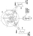
Fig. 1 has illustrated from 6 video images that are centered around object 6 video cameras on every side;
Fig. 2 has illustrated the video image of display background subduction information;
Fig. 3 has illustrated the video image of the video camera of concentrating one's gaze on big calibration substrate;
Fig. 4 has illustrated the 3D view, show 2D polygon after all camera data all are projected on it (in the case, described polygonal position provides the xsect of floor on the length direction of the pin of main body (subject)) on the right of this view;
Fig. 5 shows and 2D projection polygon is carried out recurrence uses, with " inspection " space and seek the full graphics of human body;
Fig. 6 illustrated with the skeletal graph picture with by estimating that the data that described 2D polygon generates tentatively mate;
Fig. 7 shows data texturing is projected to 2D polygon 2D polygon afterwards;
Fig. 8 has illustrated the feature of the arm that utilizes the tracking of 2D polygon in local coordinate space;
It is how to be projected onto on the 2D polygon that Fig. 9 has illustrated texture;
Figure 10 has illustrated the texture of institute's projection Fig. 9 from another viewpoint;
Figure 11 shows the layout that illustrates the relation between real world and numeric field and video camera and the virtual projection instrument;
Figure 12 shows how to set up video camera/spatial calibration;
Figure 13 shows the virtual projection cloud of crosscut video camera projection;
Figure 14 show from the video camera projected data be how by " drafting " to the 2D polygon;
Near the section that Figure 15 shows the bone that is positioned at tracked feature is how to provide positional information for next time step;
Figure 16 shows and how to use 2D section to analyze the confusion of eliminating in the complex scene;
It is the position that how to help to locate rightly tracked skeletal graph picture that Figure 17 shows " end caps ";
Figure 18 has illustrated the data flow in the example system;
Figure 19 shows the general video camera machine arrangement according to embodiment of the present invention; And
Figure 20 has illustrated the close-up illustration of the projection on the 2D polygon.
Be understandable that, above-mentioned accompanying drawing is intended to help describe theory of the present invention, but not be used to limit proportional sizes, and more non-being used for limiting aspect various possible shapes and the proportional range, and various possible shapes and ratio all drop within the scope of embodiments of the present invention.
Embodiment
Extracting in 3D and following the tracks of by the employed step of the human body that a plurality of video camera monitored according to embodiment of the present invention will be described below:
The video content of some 10 of embodiment use or more a plurality of digital video camcorders, described digital video camcorder is positioned at around the interesting areas, so that the visual angle of maximum quantity to be provided.
Described the video acquisition subsystem among Figure 18.A plurality of video cameras [1801] are sent to main frame via live wire cable [1802], ethernet ip, analog signal line or other conventional means with video.Described video enters camera acquisition plate [1803].In the embodiment of this example, we use the card of the use IEEE1394a live wire standard of customization.Generally speaking, can use the image interface plate of other type, as long as it has the function that sends video data via direct memory access (DMA) (DMA) transmission [1804].By using DMA, we can be with in the Installed System Memory of video Data Transmission to the main frame.Described data are directly moved to Graphics Processing Unit storer (GPU storer) [1805] from Installed System Memory via the DMA transmission.In the present embodiment, described GPU is client's level (consumer grade) 3D graphics card of the support DirectX of standard, and this graphics card can carry out the summit and pixel is drawn.Alternatively, we can make a video data copy simultaneously, and transmit it to hard disk array [1806] by the DMA transmission mode, in order to follow-up obtaining.Use the purpose of 100%DMA transmission to be to make host CPU to be available, to be used for other task.Above-mentioned image transfer method allows us only to use cpu cycle of about 1%, just can be with all video data playback.
Figure 11 shows how video camera is placed in main body or scanning area diagram on every side.Fig. 1 shows the screenshot capture of software, and this sectional drawing shows the particular video frequency content of the main frame of sending into when main body is arranged in setting shown in Figure 11.
I) use B: when we used B, we can use activity context, with help with main body fast from background subduction come out.In the present embodiment, described activity context is made up of backlight plate or reflecting surface, and this activity context can be realized by the light-reflecting product that is called " vision beautiful (ScotchLite) " that utilizes 3M company to be sold.Described material can be found in usually on road sign, the clothes reflecting strips or even the street on paint.If on this material, this material can be with the position of the described light ejaculation of light reflected back with irradiate light.When having light around the camera lens, these light are back to video camera can make background seem luminous.Basic thought after these Background luminescence is, even the brightest texture also can be secretly in described background in the image of main body.Two kinds of methods can be used to reduce background.We can be used alternatingly these technology according to the illumination condition of setting.In one case, we only shear the image of certain luminance level.In the case, we think that the pixel that each brightness is higher than certain threshold level all belongs to background.In Fig. 2, background is replaced by black, to help explanation.Another kind of mode of replacing the activity context of B is to obtain the reference photograph of background, then background and foreground image is carried out the subduction of individual element.Then, we can obtain the absolute value of the image that is reduced, and deduct certain threshold level.Thought herein is that difference is likely the part of prospect greater than the pixel of the specified quantitative between prospect and the background.Final subduction appears to has sheared the have high luminance values background of (as a kind of selection).By using activity context, we can the removal of images split plot design in along with main body moves in scene and causes the complicacy that variation caused of ambient lighting or shade.Backlight is eliminated or has been watered down shade.The shortcoming of this method is that we need use activity or specific reflecting surface is placed main body special photographic studio setting on every side.
Ii) use colour TV camera: when we used colour TV camera, we can have more proven technique and reduce background.Under the situation of using colour TV camera, we take snapshot for background (that is, main body is not in scanning area), and the image of taking is transformed into HLS color space (tone, brightness, saturation degree) from RGB.We carry out same processing to prospect, and use following rule:
If a foreground pixel is bright in background on saturation degree, show that then it is a foreground pixel.
If the b foreground pixel is secretly in background pixel, then it may be foreground pixel or may be the background pixel that has shade on it.Shade generally has identical tone value with its color that is influenced.In the case, we carry out quadratic search, with the tone value of judging prospect whether with the tone value close (in a certain scope) of background.If difference is little in their close and saturation degree and brightness, then we suppose that this pixel is for by the background pixel that shade influenced of main body.
If the c prospect is different with the tone value of background, even then saturation degree is identical with brightness, we also will shear described pixel, and with it as prospect.
If the difference of the saturation degree of d prospect and background has exceeded a particular range, then we also shear it, and the background transposing is prospect.
By above-mentioned rule is merged, we have developed a kind of powerful pixel background subtraction method of pursuing, and this method has overcome the brightness in the scene well and changed.This method allows us all can carry out solid-state background subtraction in indoor setting and outdoor setting, and does not need special photographic studio setting.Pursue the pixel subduction technology except described, we can also use the technology based on the zone, and this technology can be passed judgment on the graded of background than prospect.In some cases, the pixel in the prospect may be set to background mistakenly, because itself and background have close color value.But because the gradient difference of neighbor (for example, between prospect and background in the opposite direction from bright deepening), so we can suppose that in fact described pixel is not background pixel.
Fully utilizing above-mentioned technology allows us to set up solid-state background subtraction under the illumination condition (for example daytime) of complexity.Compare with above-mentioned black-white technique, the weak point of this technology is and can causes huge performance hit to the system with all these additional calculations.These two kinds of technology all can be passed through the projecting method real time execution, in this article, we will after projecting method is described.
The point that background subtraction noted:
At this, we have described the theory of background subtraction.In our method, we are not in 2D rank or pre-treatment step subduction background.We are projected to scene with background in the mode identical with our projection video (as described below).This makes us to be projected to 2D polygon (perhaps section) (as described below) afterwards in data, fully freely utilizes described data.
Lens on the video camera can warp image.When observing by fish-eye lens or pantoscopic lens, can be very obvious.Around the edge, straight line has crooked trend.Rebuild for the object that can successfully look video camera, we need correct these images, and the image shift that optical properties caused of offset lens.Have only when we can compensate these distortions, the straight line of all projections just can correctly poly-friendship in numeric field when we rebuild real scene.In order successfully to reach this purpose, we must at first obtain lens parameter accurately.This parameter comprises following content: on X and Y direction accurately, (this is the numerical value on the lens to perhaps approximate focus accurately, 6mm for example, but we need calculate actual numerical value, for example this numerical value may be about 6.0231mm), on X and Y direction accurately the lens center (this be tolerance lens be how to be mounted to imageing sensor, manufacturer places lens at the center of imageing sensor, but we need know be accurate to this value that is lower than a pixel or 0.002mm), in the lens deflection of X and Y direction (because this value, camera lens fail the straight video camera that is installed on).We use plural value to be given in from the lens center to the difference at edge, and how focal length changes.
Step 1: we show a checkerboard pattern to lens, and from about 30 images of different angle shots.System detects these trellis patterns automatically, and calculates the point of crossing of all grids on the chessboard.This can make system obtain 30 groups of points.According to these points, system can use very known algorithm to calculate all lens parameters.
Step 2: after we calculated lens parameter, we needed the position of calibration camera.At this, we use bigger chessboard, and are placed on scene central authorities.Each can see photo of video camera shooting of chessboard, and detects grid and point.Though we use known method to obtain the position of video camera with respect to chessboard, at this, we have designed a kind of technology that makes us can improve degree of accuracy.We constantly take pictures by all video cameras (100 or more), and then based on the position of each video camera with respect to chessboard, set up the location diagram (referring to Figure 12) between all video cameras.
Then, we place chessboard on the floor, and obtain the position of a video camera with respect to the chessboard on the floor.The upper left corner grid of the chessboard on the floor becomes the X of scanning space and the initial point of Y direction, and the vector that makes progress (stretching out from chessboard) becomes the Z vector.Because each video camera is all known the relative position between itself and other each video camera, therefore, the grid square that the video camera that can observe chessboard best can make video camera is corresponding with the chessboard initial point on position and direction.Now just known the position of each video camera with respect to the chessboard initial point.The camera coordinates grid is unimportant to the degree of accuracy of initial point, so we have only used a sample.Yet for video camera relative position each other, we have used up to a hundred samples.By adopting standard deviation and removing exceptional value by calculating, we can further improve this.Have now found that we can make each video camera reach time millimetre-sized precision with respect to the XYZ position of initial point.Fig. 3 shows from the view of a plurality of video cameras of large chessboard more.
Step 4, by projection on the 2D surface to carry out image reconstruction
After we reduced background and obtain the accurate position and lens attribute of each video camera, we just can realize our technological breakthrough: we can be with those image projection to the 2D surface.For with video-projection to the surface, we adopt the technology of being used always in the 3D graphics to come shade in the projection 3D scene.Exist many very known by using DirectX or OpenGL to come projection shade, light source or even the technology of video to the 2D polygon texture.These technology relate to the UV texture coordinate of the just coloured 2D section of distortion, to read the texture that just is being projected.In the present embodiment, the texture that just is being projected is the 2D video flowing.These technology are easy to be understood in the 3D field of Computer Graphics.The following discloses content has provided a good domain background:
Mark Segal, Carl Korobkin, Rolf van Widenfelt, Jim Foran and PaulHaeberli, " Fast shadows and lighting effects using texture mapping ", SIGGRAPH Comput.Graph., vol.26, no.2,1992, issn.0097-8930, pp.249-252.The content of the document is incorporated into this as a reference.
In order to simulate, computing machine mainly is that video projector is carried out emulation.In 3D emulation, we are assumed to be a video projector with each video camera.At each video camera, the video content that we fall the image of background with subduction or have an image of background projects in the 3d space.Thought herein is, each video camera carries out projection from the definite position of real camera with definite real camera lens attribute in definite direction with video content.In fact, we are reversing real world institute occurrence.At real world, all reach a plurality of video cameras of native system from the light of all objects from main body.In the 3D of numeric field model, the thing that these images are done is just opposite---and system will be projected to the emulation chamber with identical definite lens attribute from the light of video camera.When all video cameras were correctly calibrated, those light can intersect (referring to Figure 13) in the mode identical with its mode that spreads out of from object in real world the 3D numeric field.
Figure 19 has provided comparing one by one between real world and the numeric field.Theoretical space in " data cloud " expression numeric field.Be used to represent that all data of real world all are obtainable, but we only have by polygon being placed this space, can really video data be projected to the surface.By the 2D polygon is placed this projector space, we can catch these emulation light.We can realize this purpose by following steps: if prospect texture (that is, non-black) touches the pixel on the slice surface, then we can add count value one or add a certain amount (by this amount, described pixel can be distinguished mutually with background).After all video cameras were projected to described section, we calculated increment.If increment equals the quantity (perhaps a little bit smaller slightly numerical value) of the video camera of our institute's projection, then we can determine, necessary being solid object in this pixel space.Thereby the solid pixel is illustrated in the solid object that is positioned at described accurate location in the real world.We utilize a plurality of 2D polygonal slices to rebuild the 3D scene.When we are arranged in a plurality of sections in the scene from the top down, seem to be similar to especially the MRI imaging system.By obtaining all xsects in this way, we can see in the section of people's reproduction in numeric field that stands on real world truly.The section that we use is many more, and then image can become accurate more.
How two points that Figure 14 shows in the video data link up on polygon.Figure 20 shows by the section among feature Figure 19 3 and shows same intersection in a different manner.In the case, the part light of right arm is how to go out and meet correct place in section from each projector projection as can be seen.Please note the dotted line section on the 2D picture [2001].They give the appearance when section is projected back video camera.
In this way, polygon (that is, 2D section) was cut the space effectively, and " view " of the real world of a shot by camera be provided.Now, we can generate the section xsect of real world by described polygon being placed the Virtual Space.Data and described section very similar (noticing that MRI uses diverse technology) from MRI (in MRI, you can obtain section by the xsect of human body).We can obtain identical xsect, but undoubtedly, we can't see the situation in the body.We have only obtained the peripheral profile of section and the texture (the real video image of the surf zone of xsect) in the outside.
Why so special? present technique uses the volume reconstruction known technology of a plurality of video cameras to compare with other, mainly has following difference:
1, resolution is independently.The sharpness of section is determined by the resolution of the section grain surface that we played up.This means that we can dynamically select the attribute of cutting into slices.We can select the putting position of cutting into slices and towards.We can select represented " real world dimensions " (that is, and 1 meter wide or 5cm is wide?).We can select resolution (that is, the 2D section is made of 10 * 10 pixels, still is made of 1000 * 1000 pixels).Dynamically the real world in " observation " and " inspection " the 3D virtual projection system (numeric field) allows us to carry out some very useful operations: we can judge immediately that now which content is that we need examine, and which of object partly is unessential.For example, following the tracks of under the situation of human action, we can observe chest with lower resolution now, then the finger that we can the object of observation.By avoiding method for reconstructing based on volume elements, the model that we can avoid look-up table fully and depend on resolution, look-up table and depend on that the model of resolution is this area part of difficult research.
2, we can be at the designed 3D vision hardware (Graphics Processing Unit-GPU) redesign in up-to-date retail video game market.The hard connection features that this technology allows us directly to use the research institute of multi-billion dollar fund in 3D figure and the video-game to develop, and redesign them according to our needs.Texture is carried out the great part that projection makes the light in the video-game become more true to nature.By using our microtomy, we can be by this ability of this technology, and uses it in brand-new mode.In this way, we have realized that hardware-accelerated projection quickens to play up, and make it than based on the method for CPU fast 100 or even 1000 times.
3, very fast.Many known technologies are fast 100 ten thousand times in the comparable this area of motion capture technology described below.
4, the dynamic resolution technology allow we obtain Billy use based on the method for volume elements the higher resolution of resolution that may reach.Our normally used resolution is 200 times of the known resolution that operates in the system on the volume elements model.
5, except main 3D Model Reconstruction, we can use this microtomy to solve the many other problemses that solved before in the computer vision field but do not solved in the 2D territory in the third dimension.For example, utilize section, we can follow the tracks of texture and xsect (will be explained hereinafter) in the 2D territory effectively, calculate their 3D position then at next step.Thereby we can be effectively obtain 3D rendering with the cost of 2D image processing techniques and handle.We can redesign the many 2D image techniques that may cannot work effectively forever in the 3D environment.
6, can expand.Set up the vision framework based on section is easy to expand very much.By using a plurality of servers and up to a hundred video cameras, can set up a system, and each independent section can be chosen relative correct video camera and played up by be in position in the space based on it.Can allow us to have like this and be equipped with main facilities and the ability of tracing object in big quantity space with video camera.
Step 5, the 2D graphical analysis is carried out in section
As mentioned above, one of largest benefit of projection microtomy is to utilize traditional image processing techniques, and they can be projected in the 3D territory afterwards.The first step that we use is that the object that we are found in the 2D section is classified.Object is defined as the continuous xsect on the 2D.We are referred to as block (blob) with them.In case we isolate independent block, we can use various known 2D curve fitting algorithms.Spendable a kind of routine techniques be with ellipse fitting to described block.This can draw positional value, X-axis radius, Y-axis radius and the anglec of rotation of central point on X-axis and Y-axis of block.In this way, we can enter into original 2D data from original 3D data by using slice systems, and afterwards by simply with the 2D ellipse fitting to the original block point and enter into spendable vector data from original 2D data.
Then, we obtain the 2D vector data for next step, and are applied to by the attribute of will cutting into slices and obtain its 3D attribute on this 2D vector data.The resolution that we consider the position of cutting into slices and direction, section with and size in real world.Like this, we can be converted to the XY position of the pixel on the ellipse XY coordinate in the real world space (that is, with respect to the distance of the initial point of floor calibration substrate, this distance is the millimeter magnitude).
In this way, we have only generated the 3D vector data of real-world objects by some simple steps.
Fig. 4 shows our system and is positioned at single section on the floor of object foot.By above-mentioned shadow casting technique, we have found " footprint " of main body.Then, we use above-mentioned ellipse fitting technology.Red cross has carried out mark to the central point of the object in the section.Two two-dimentional windows of the section on the screen show the true texture of the section in the 3D view.
Step 6, model detect
We detect the humanoid method of stepping into the space:
A, section is placed on the floor, and seek footprint.We are by analyzing section and seeking " block " with the general size attribute of pin and seek footprint.If find them, then:
B, several inches parts on described section are placed another section.They are ankles.If we search out ankle, just then we can determine the people towards direction.Toe should be away from described ankle.
C, then, we place the present height of knee, buttocks, chest and head with section.We place some sections around the head, find out people's height to try.
D, we by the angle of observing trunk seek human body towards.
E, we are by section being placed the either side of human body, seek arm.
After having checked all these tests, we just can be one and be in the humanoid of particular pose with what very high accuracy determined that we are faced.Such graphical examples has been shown among Fig. 5.
Technology that in case we have used is above-mentioned " sampling flexibly ", and what determine roughly that we are faced is after the human body, and we enter next stage.We use based on physics, joint, quality and heterodromous cloth doll system.We apply power for this cloth doll, and it is moved to us assert the present position of arm, hand, head and pin.We suppose that tentatively cloth doll " bone " meets the oval central cross-section that we place the section in the space.Utilize step 7, we can be roughly be complementary the 3D data of model and real world.In order to explain this technology, the system that Fig. 6 shows us is added into 2D section framework with cloth doll.
Step 8, model following:
In step 8, we are to placing the mechanism on the cloth doll to operate section.From the angle of cloth doll (and no longer from angle of overall reference point), we have placed the section corresponding to everyone body region.These sections by with fixing towards " attached " to bone.We calculate all central points, and find out the poor of elliptical center and bone center.Then, we apply power for described model, so that this model is further near the position in the 3D data.Referring to Figure 15, in this way, we can imitate cloth doll, and make it as the people in the real world, this moment the people become a puppet teacher, cloth doll then is a pantomimist, this pantomimist under puppet teacher's control with data projection to the 3D Computer Simulation.We repeatedly repeat following process by per second: main body moves, camera record and upgrade them and be projected to projection in the 3D emulation.Section is placed on around each cloth doll bone, and the position of its position with the ellipse that is generated compared.Apply power for then described cloth doll, so that each cloth doll bone progressively shifts near the center of the xsect of the section of representing true main body.
The thing that we should be noted that when following the tracks of bone in the above described manner is:
Interference between the object: for example, when following the tracks of arm, just exist problem during near health at this arm.At this moment, two independent blocks, an xsect that belongs to arm, an xsect that belongs to health is to such an extent as to they lean on to such an extent that too closely they have formed a block.So just be difficult to judge where which object belongs to.In the case, we are by using cloth doll and it being checked, with head it off.Because cloth doll is to move with real physiognomy mode together, we can suppose that cloth doll is very similar to True Data.Near must being enough under the situation of " contact ", we use a kind of way to calculate to incorporate the little block of big block may become very maximum likelihood near the situation of the arm of health at two bones.Can obtain detail referring to Figure 16.Because we know the diameter of arm and the diameter and the relative position of health, so we can suppose that little arm block is to be positioned within the bigger health block.This technology be proved prevent that body part from sticking together and tracker analyzed aspect very effective.
End caps: the section that we will seek the body extremity position is referred to as end caps.The body extremity position comprises hand, pin and head.End caps has been guaranteed the limit that we extend cloth doll.Referring to Figure 17, arrive appropriate position by making hand, pin and head, we have realized the best model coupling.As top, we are applied to end caps with the model cognition technology.If a hand is near the another hand, then we regulate our dynamics, " incorporate " the another hand to prevent a hand.
Step 9, use texture:
As mentioned above, projecting to one of largest benefit in the section is to use the 2D image processing techniques on the 3D model.
In case we have mated and traced into by the xsect that uses section our cloth doll, we can improve the position of our model by second step.By the superficial makings of analytical model, we can further locate cloth doll, with real world in the role be complementary.
Above-mentioned how work:
When cloth doll during very near real people's position, we can be according to surface segment but not xsect is placed " section ".For example, we can place section the chest of main body.The profile of this section can determine that this profile has shown the profile of the chest that intersects with described section by the method identical with definite xsect.But because we know the position of this section with respect to all video cameras, thus we can determine and according to a plurality of video camera projector that are positioned at the optimum position play up the true texture of projection.Now, chest has not only had body contours, but also has had " outward appearance " and the texture of health by video.We can be placed on these sections around the health, and model is had and true identical " outward appearance " of main body.More importantly be, we can analyze each 2D section now, and follow the tracks of the displacement of texture self, to produce higher precision.
The first step: make cloth doll meet the profile (that is oval location) of section;
Second step: after the very close real people's of cloth doll position, we can place section the surface of main body.This will provide real people's 3D texture to us.Then, we can follow the tracks of these textures, with the location of further improvement cloth doll.The example that texture is projected to section sees also Fig. 7 and Fig. 8.
We use known technology of carrying out texture tracked on the 2D surface.For each section, we compare " image " or texture and reference picture that we obtain from the same section of animation sequence section start.Then, we decide by the position difference (that is, X value and Y value) and the angle that they rotated of two textures.The unique distinction of this process is that afterwards, we use X value and Y value and angle-data among the described 2D, and to use oval much the same mode to calculate its 3D position.We obtain section self the position and towards, and infer whether the variation among the 3D true.We are offset according to this increases the dynamics that imposes on cloth doll, with after it initially meets ellipse, and further accurate its position in second step.In this second step, we have obtained very high precision, this precision even surpassed present usage flag and the precision based on the motion capture system of mark of pantie-corselette trousers.
Fig. 9 and Figure 10 show us and how section are placed the chest of model, and will be projected on the model from the texture of video image.The texture of institute's projection is shown in the 2D window in the image lower left corner.
Sum up:
By being projected to 2D section (2D polygon), we have realized the important breakthrough of computer vision.Can allow us to come (chasing in the process of human body) to approach organic object like this, and allow them in the 3D territory, work more effectively at us by many known technologies of using and redesign in the 3D field.Make us can set up first real-time unmarked motion capture system in the world like this, this system can be to put on the identical speed and the resolution operation of system of specific markers and pantie-corselette trousers are followed the tracks of them to help vision computer target with needing object.
The lime light of relevant GPU hardware:
Embodiments of the present invention are utilized Redeon 9700 graphic process unit.The Redeon processor is can be based on first GPU of the described projection algorithm operational hardware of the application.Initial slice systems realizes by using shader model 1.4, and this shader model 1.4 is state-of-the-art at that time tinter systems.
By introducing the GPU tinter of 3.0 versions, we just can realize whole shadow casting technique in a step.This means that we can calculate all contents from lens distortion, background subtraction and even projection etc. in single step, and by instantiation, we utilize single GPU to call just all sections in can optical projection system.
Embodiments of the present invention can comprise new method and system, and this new method and system is by being projected to the 2D polygon surface with a plurality of camera video streams in the numeric field, to rebuild real-world objects with the 3D form in the numeric field of computing machine.Described new system comprises 2 or a plurality of video camera, video camera collection or input port, the main frame with dma controller, CPU (central processing unit) and/or Graphics Processing Unit.
The embodiment of native system can utilize DirectX or OpenGL accelerated graphics card to quicken the calculating of polygon surface projection.The embodiment of native system can use IEEE 1394 standards to come transmit image data.The embodiment of native system can use Ethernet to come transmit image data.
The embodiment of native system can use wireless network protocol to come transmit image data.The embodiment of native system can be projected to video data and background data on the polygon at each video camera.The embodiment of native system can convert the texture pixel of 2D projection polygon surface to the coordinate in the 3D world.
The embodiment of native system can be used to follow the tracks of human body.The embodiment of native system can be used for following the tracks of animal.The embodiment of native system can be used for imitating 3D role.The embodiment of native system can be used as the direct-view teaching aid in the karaoke OK system.
The embodiment of native system can use the 2D image processing techniques to the data that are projected to from video camera on the 2D polygon.The embodiment of native system can use 2D shape fitting technique to calculate the 2D shape that is generated on the projection polygon.The embodiment of native system can reduce institute and have powerful connections after all data are projected onto on the 2D polygon.
The embodiment of native system can use B and 3M ScotchLite reflectorized material to quicken and simplify the background subtraction process.The embodiment of native system can use colour TV camera.The embodiment of native system can use summit and fragment shader that section projection calculation from CPU is moved to GPU.
But the embodiment recurrence of native system utilize institute's projection and by analysis after polygon, where next polygon should be placed on to calculate, to promote research the shape of reconstructed object.The embodiment of native system can be projected to the 2D polygon with video texture based on the allotment between the video camera, and described allotment is based on the inclination angle of video camera with respect to the polygon normal.The embodiment of native system can use the 2D optic flow technique to follow the tracks of discrepancy in the texture that is projected onto on the 2D polygon.
The embodiment of native system can be used as the part of motion capture system, not need usage flag or to enclose under the situation of tracking equipment, tracking and digitizing people's action.The embodiment of native system can be used for measuring the size of human body, and calculates accurate rotation binding site by the action of analyzing main body.The embodiment of native system can be used for analyzing the netman: analyze player's the swing and the action of health, improving results, and avoid shoulder, elbow, ankle injured.
The embodiment of native system can be used for research and development, with when main body is used specific products, and the action of study subject.The embodiment of native system can be used for analyzing the action of slider/skis, to improve results and to avoid injury.The embodiment of native system can be used for simulating and playing by the TV radio network virtual role of true main body.
The embodiment of native system can be used as the part of man-machine user interface.The embodiment of native system can be used as the part of security system.The embodiment of native system can be used for making human body and sports goods equipment (for example, bicycle, golf club, clothes and/or shoes) to be complementary.
The embodiment of native system can be used as the part of visual simulation or training system.The embodiment of native system can be used for calculating body shape, size or vital signs, for example breathing mechanics.The embodiment of native system can be used as the part that public entertainment is experienced.The embodiment of native system can be used as the part of body-building, teaching evaluation or commending system (recommendation system).
The embodiment of native system can be used as the part of physical rehabilitation system.The embodiment of native system can be used as the part of diagnostic action analysis or assessment tool.The embodiment of native system can be used as the part of disabled rescue.The embodiment of native system can be used as the part of training tool.
The embodiment of native system can be used as the part of virtual reality visualization system.In some embodiments of the present invention, the above-mentioned institute of described method can carry out by computing machine or computer system in steps.In optional embodiment, one or more step in the described step can manually be carried out by the people.
In the optional embodiment of method described herein, other step can be added, some step can be got rid of, some step can repeatedly be carried out and/or described step can be different order and/or execution simultaneously.
It will be appreciated by persons skilled in the art that enforcement of the present invention is not limited to described embodiment, described embodiment only is the purpose of property presented for purpose of illustration, but not is used to limit the present invention.Those skilled in the art can carry out various adjustment to described embodiment under the situation that does not deviate from essence of the present invention and scope, scope of the present invention only is as the criterion with the scope that appended claims was defined.
Claims (according to the modification of the 19th of treaty)
1, a kind of being used for created the method that the 3D of destination object represents at the 3D numeric field, and this method comprises:
(i) described destination object is placed in the spatial context;
(ii) at least two video cameras are concentrated one's gaze on described destination object;
(iii) gather complete image from each described video camera of concentrating one's gaze on described destination object;
(iv) from each described complete image, reduce described spatial context, to produce the target image of described destination object;
(v) each described video camera is carried out internal calibration;
(vi) both or many persons in the described video camera are carried out corresponding external calibration; And
(vii) by in the described target image one or more is projected to the 3D rendering that described 3D numeric field is rebuild described destination object.
2, method according to claim 1, wherein, described background subtraction, interior video cameras calibration and image reconstruction step are executed sequentially.
3, method according to claim 1, wherein, described background subtraction, interior video cameras calibration and image reconstruction step are carried out basically simultaneously.
4, method according to claim 1, wherein, corresponding external camera calibration steps was carried out before image acquisition step.
5, method according to claim 1, wherein, the interior video cameras calibration comprises the distortion of analyzing at least one lens on each described video camera, and any image shift that is caused by the optical properties of these lens is compensated.
6, method according to claim 5, wherein, described interior video cameras calibration also comprises the attribute that calculates described lens, and this attribute is selected from the group that is made of the following: the focus of described lens, described lens central point and the deflection of described lens after it is mounted to described video camera after it is mounted to described video camera.
7, method according to claim 6, wherein, the step of the attribute of the described lens of described calculating comprises:
(i) checkerboard pattern is placed in the described spatial context, so that described video camera is from one or more images of the described checkerboard pattern of a plurality of angle acquisitions;
(ii) determine the point of crossing of each grid on described one or more images of described checkerboard pattern; And
(iii) use described intersection calculations lens parameter.
8, method according to claim 7 wherein, is gathered at least 30 or more a plurality of image of described checkerboard pattern.
9, method according to claim 1, wherein, at least 5 or more a plurality of video camera are concentrated one's gaze on described destination object.
10, method according to claim 1, wherein, at least 10 or more a plurality of video camera are concentrated one's gaze on described destination object.
11, method according to claim 1, wherein, at least one in the described video camera is selected from the group that is made of the following: digital video camcorder, analog video camera, black and white video video camera and color video video camera.
12, method according to claim 1, wherein, described background subtraction comprises:
(a) activity context is placed in the described spatial context, and make described activity context be positioned at described destination object rear;
(b) make described activity context luminous;
(c) judge whether each pixel of described image is bright in predetermined threshold;
(d) will be judged as bright each pixel and be characterized by background pixel, and will be judged as secretly in each pixel of described predetermined threshold and be characterized by foreground pixel in described predetermined threshold; And
(e) keep each foreground pixel, with image as described destination object.
13, method according to claim 1, wherein, described background subtraction comprises:
(a) before placing described destination object in the described spatial context, obtain the background image of described spatial context;
(b) after placing described destination object in the described spatial context, obtain the foreground image of described target;
(c) background image from described foreground image execution individual element reduces;
(d) all pixels that will still be retained in the described foreground image are characterized by foreground pixel; And
(e) keep each foreground pixel, with image as described destination object.
14, method according to claim 1, wherein, described background subtraction comprises:
(a) before placing described destination object in the described spatial context, obtain the background image of described spatial context;
(b) after placing described destination object in the described spatial context, obtain the foreground image of described target;
(c) in described background image and the described foreground image each is transformed into tone-brightness-saturation degree color space;
(d) characterize pixel in the described color space according to being selected from one or more rule in the group that constitutes by the following:
(i), then the described pixel in the described foreground image is characterized by foreground pixel if the pixel in the described foreground image is higher than respective pixel in the described background image on saturation degree;
If the pixel in the (ii) described foreground image is lower than respective pixel in the described background image on saturation degree, and the tone value of the described pixel in the described foreground image is in the preset range of tone value of the described respective pixel in the described background image, and described pixel in the described foreground image and saturation degree and the luminance difference between the described respective pixel in the described background image do not exceed preset range, then the described pixel in the described foreground image are characterized by background pixel;
If the tone value of the pixel in the (iii) described foreground image has exceeded the preset range of the tone value of the described respective pixel in the described background image, then the described pixel in the described foreground image is characterized by foreground pixel; With
If (iv) the difference of the saturation degree of prospect and background has exceeded predetermined difference, then pixel is characterized by prospect, shear the difference of described saturation degree, and described background is set to prospect so that type of pixel to be set; And
(e) keep each foreground pixel, with image as described destination object.
15, method according to claim 1, wherein, described background subtraction comprises the technology of use based on the zone, the described spatial context of this technical Analysis is than the graded of foreground spatial.
16, method according to claim 1, wherein, corresponding external camera calibration comprises:
(a) checkerboard pattern is placed in the described spatial context, so that each described video camera is from one or more images of the described checkerboard pattern of a plurality of angle acquisitions;
(b) obtain the one or more images that are positioned at the described checkerboard pattern on each described video camera;
(c) determine the point of crossing of each grid on described one or more images of described checkerboard pattern; And
(d) position of using described point of crossing to calculate each described video camera.
17, method according to claim 16, this method also comprise based on the relative position of each described video camera with respect to described checkerboard pattern, create the location diagram between each described video camera.
18, method according to claim 17, wherein, the establishment of described location diagram comprises:
(a) judge which video camera in the described video camera is in the optimum position of the image that obtains described chessboard; And
(b) with the every other video camera in the described video camera towards the video camera that is judged as the optimum position that is in the image that obtains described chessboard.
19, method according to claim 18, this method also comprises basis of calculation deviation, and removes exceptional value from described result of calculation.
20, method according to claim 1, wherein, carrying out image reconstruction via one or more images of gathering to the projection of described 3D numeric field comprises: under the lens attribute of described video camera, from the present position of described video camera and with described video camera towards direction, will gather described image projection from each described video camera to described 3D numeric field.
21, method according to claim 20, wherein, described image reconstruction supports the hardware of tinter language to finish by using.
22, method according to claim 20, wherein, described image reconstruction also comprises:
(a) in described 3D numeric field, make up one or more virtual projection instrument, and these one or more virtual projection instrument are had and the similar configuration of described one or more video cameras;
(b) one or more virtual 2D sections are inserted in the described 3D numeric field;
(c) image of each described virtual 2D section with each projection compared;
(d) when the image of institute projection and a described virtual 2D section are intersected, increase count value;
(e) quantity of more described count value and described one or more video cameras; And
(f) judge whether described destination object should be present in described virtual 2D section present position in described 3D numeric field.
23, method according to claim 22, wherein, described image reconstruction also comprises the characteristic that dynamically disposes each described virtual 2D section, with the optimum matching of realization with the characteristic of described destination object.
24, method according to claim 22, wherein, each described virtual 2D section is inserted in the described 3D numeric field, other described virtual 2D cuts into slices and parallels so that each described virtual 2D section is with each.
25, method according to claim 1, wherein, described method also comprises the described destination object of following the tracks of in the described 3D numeric field.
26, method according to claim 25, wherein, described method also comprises the superficial makings that detects described destination object; And the superficial makings of following the tracks of described destination object.
27, method according to claim 25, wherein, follow the tracks of described destination object and comprise:
(a) each image gathered that is projected to described 3D numeric field is carried out the 2D graphical analysis;
(b) detect the existence of described destination object based on the known features of described destination object; And
(c) the cloth doll virtual representation of the described destination object of establishment in described 3D numeric field.
28, method according to claim 26, wherein, described 2D graphical analysis comprises:
(a) assessment is used for each virtual 2D section of one or more graphical representation structures;
(b) calculate the profile of each described graphical representation structure;
(c) with ellipse fitting to each described graphical representation structure;
(d) calculate central point, x axle radius, y axle radius and the anglec of rotation of each described graphical representation structure; And
(e) the known attribute with each virtual 2D section is applied to each the described graphical representation structure that is positioned at described virtual 2D section, to generate the real world coordinates of each described graphical representation structure.
29, method according to claim 26, wherein, detect described destination object and comprise:
(a) in described 3D numeric field, make up one or more virtual projection instrument, and these one or more virtual projection instrument are had and the similar configuration of described one or more video cameras.
(b) one or more virtual 2D sections are inserted into one or more positions of being scheduled to based on the known features of described destination object in the described 3D numeric field;
(c) image of each described virtual 2D section of comparison and each projection;
(d) when the image of institute projection and a described virtual 2D section are intersected, increase count value;
(e) quantity of more described count value and described one or more video cameras;
(f) judge whether described destination object should be present in described virtual 2D section present position in the 3D numeric field;
(g) assessment is used for each virtual 2D section of one or more graphical representation structures;
(h) calculate the profile of each described graphical representation structure;
(i) with ellipse fitting to each described graphical representation structure;
(j) calculate central point, x axle radius, y axle radius and the anglec of rotation of each described graphical representation structure; And
(k) the known attribute with each described virtual 2D section is applied to each the described graphical representation structure that is positioned at described virtual 2D section, to generate the real world coordinates of each described graphical representation structure.
30, method according to claim 29, wherein, described destination object is a human body, and described method also comprises:
(a), insert the virtual 2D section that is parallel to described floor at the floor level place;
(b), insert the virtual 2D section that is parallel to described floor at ankle-joint height place;
(c), insert the virtual 2D section that is parallel to described floor at the knee height place;
(d), insert the virtual 2D section that is parallel to described floor at the hip height place;
(e), insert the virtual 2D section that is parallel to described floor at the chest level place;
(f), insert the one or more virtual 2D section that is parallel to described floor at the height of head place.
31, method according to claim 29, this method also comprise by analyze at described floor level place and be parallel to one or more graphical representation structures in the virtual 2D section on described floor and the relation between the one or more graphical representation structures in described ankle-joint height place and the 2D that is parallel to described floor cut into slices judge described human body towards.
32, method according to claim 29, wherein, judge described human body towards comprising that also analysis is at described hip height place and be parallel to one or more graphical representation structures in the virtual 2D section on described floor and the relation between the one or more graphical representation structures in described chest level place and the 2D that is parallel to described floor cut into slices.
33, method according to claim 32, this method also comprises the height of judging described human body.
34, method according to claim 33, this method also comprise inserts one or more virtual 2D sections as end caps, to judge the edge of described destination object.
35, a kind ofly be used to create and the system that represents of the 3D of tracking target object optionally, this system comprises:
(i) concentrate one's gaze at least two video cameras of described destination object;
(ii) be coupled to one or more the one or more video camera images acquisition modules in the described video camera; And
(iii) at least one is based on the device of processor, this device comprises direct memory access (DMA) controller and Graphics Processing Unit, wherein said device based on processor is coupled to described one or more video camera acquisition module, and be configured to carry out at least following steps: gather image from described image capture module, carry out the interior video cameras calibration function, the execution background subtraction is handled, and the carries out image reconstruction process.
36, system according to claim 1, wherein, at least 5 or more a plurality of video camera are concentrated one's gaze on described destination object.
37, system according to claim 36, wherein, at least 10 or more a plurality of video camera are concentrated one's gaze on described destination object.
38, system according to claim 1, wherein, at least one in the described video camera is selected from the group that is made of the following: digital video camcorder, analog video camera, black and white video video camera and color video video camera.
39, system according to claim 1, wherein, each video camera in described at least two video cameras is positioned at around the described destination object, provides the independent visual angle of obtainable maximum quantity to utilize this number of video video camera.
40, system according to claim 1, wherein, at least one in described one or more video camera images acquisition module connects the connection in the group that is constituted and is coupled to one in the described video camera via being selected from by live wire connection, Ethernet connection, wireless connections and simulation.
41, system according to claim 1, wherein, described based on the client level 3D graphics card of the described Graphics Processing Unit in the device of processor for support DirectX, this graphics card can carry out the summit and pixel is drawn.
42, according to the described system of claim 41, wherein, described Graphics Processing Unit is the Redeon9700 graphic process unit.
43, system according to claim 1, wherein, described device based on processor is coupled to described one or more video camera acquisition module via the direct memory access (DMA) transmission.
Claims (2)
1, a kind of method of following the tracks of three dimensional object, this method comprises:
The image that comprises described object from a plurality of camera acquisitions;
Reduce the background of described image;
In the described video camera at least one calibrated;
Rebuild described image by on two-dimensional surface, carrying out projection;
Analyze described image;
Detect one or more model;
Mate described one or more model;
Follow the tracks of described one or more model;
Analyze described one or more mold surface texture; And
Follow the tracks of described superficial makings.
2, a kind of system that is used to follow the tracks of three dimensional object, this system comprises:
A plurality of video cameras are used to take the image that comprises described object;
Be coupled to the video camera acquisition module of described a plurality of video cameras; And
The main frame that comprises at least one direct memory access (DMA) controller and pattern process module;
Described system is configured to carry out following steps:
The image that comprises described object from a plurality of camera acquisitions;
Reduce the background of described image;
In the described video camera at least one calibrated;
By on two-dimensional surface, carrying out projection to rebuild described image;
Analyze described image;
Detect one or more model;
Mate described one or more model;
Follow the tracks of described one or more model;
Analyze described one or more mold surface texture; With
Follow the tracks of described superficial makings.
Applications Claiming Priority (3)
| Application Number | Priority Date | Filing Date | Title |
|---|---|---|---|
| US89273807P | 2007-03-02 | 2007-03-02 | |
| US60/892,738 | 2007-03-02 | ||
| PCT/US2008/055728 WO2008109567A2 (en) | 2007-03-02 | 2008-03-03 | System and method for tracking three dimensional objects |
Publications (1)
| Publication Number | Publication Date |
|---|---|
| CN101681438A true CN101681438A (en) | 2010-03-24 |
Family
ID=39739061
Family Applications (1)
| Application Number | Title | Priority Date | Filing Date |
|---|---|---|---|
| CN200880013274A Pending CN101681438A (en) | 2007-03-02 | 2008-03-03 | System and method for tracking three dimensional objects |
Country Status (8)
| Country | Link |
|---|---|
| US (1) | US8471848B2 (en) |
| EP (1) | EP2135197A4 (en) |
| JP (2) | JP2010520565A (en) |
| KR (1) | KR20090130003A (en) |
| CN (1) | CN101681438A (en) |
| AU (1) | AU2008222933A1 (en) |
| CA (1) | CA2717485A1 (en) |
| WO (1) | WO2008109567A2 (en) |
Cited By (5)
| Publication number | Priority date | Publication date | Assignee | Title |
|---|---|---|---|---|
| CN102521520A (en) * | 2011-12-22 | 2012-06-27 | 北京像素软件科技股份有限公司 | Camera control method applied into 3D (three-dimensional) online games |
| CN103503468A (en) * | 2011-05-05 | 2014-01-08 | 国际商业机器公司 | Incorporating video meta-data in 3D models |
| CN103617317A (en) * | 2013-11-26 | 2014-03-05 | Tcl集团股份有限公司 | Automatic layout method and system of intelligent 3D (three dimensional) model |
| CN104983426A (en) * | 2015-05-27 | 2015-10-21 | 蝶和科技(中国)有限公司 | Virtual reality bedside rehabilitation training system and method |
| CN110753930A (en) * | 2018-12-29 | 2020-02-04 | 深圳市瑞立视多媒体科技有限公司 | Fitting processing method of three-dimensional trajectory data and optical motion capturing method |
Families Citing this family (63)
| Publication number | Priority date | Publication date | Assignee | Title |
|---|---|---|---|---|
| US20090213123A1 (en) * | 2007-12-08 | 2009-08-27 | Dennis Allard Crow | Method of using skeletal animation data to ascertain risk in a surveillance system |
| US8565476B2 (en) | 2009-01-30 | 2013-10-22 | Microsoft Corporation | Visual target tracking |
| US8577084B2 (en) | 2009-01-30 | 2013-11-05 | Microsoft Corporation | Visual target tracking |
| US8565477B2 (en) | 2009-01-30 | 2013-10-22 | Microsoft Corporation | Visual target tracking |
| US8577085B2 (en) | 2009-01-30 | 2013-11-05 | Microsoft Corporation | Visual target tracking |
| US8588465B2 (en) | 2009-01-30 | 2013-11-19 | Microsoft Corporation | Visual target tracking |
| US8267781B2 (en) | 2009-01-30 | 2012-09-18 | Microsoft Corporation | Visual target tracking |
| US8682028B2 (en) | 2009-01-30 | 2014-03-25 | Microsoft Corporation | Visual target tracking |
| US8773441B2 (en) * | 2009-07-10 | 2014-07-08 | Pixar | System and method for conforming an animated camera to an editorial cut |
| US7961910B2 (en) | 2009-10-07 | 2011-06-14 | Microsoft Corporation | Systems and methods for tracking a model |
| US8564534B2 (en) | 2009-10-07 | 2013-10-22 | Microsoft Corporation | Human tracking system |
| US8963829B2 (en) * | 2009-10-07 | 2015-02-24 | Microsoft Corporation | Methods and systems for determining and tracking extremities of a target |
| US8867820B2 (en) * | 2009-10-07 | 2014-10-21 | Microsoft Corporation | Systems and methods for removing a background of an image |
| US8284157B2 (en) * | 2010-01-15 | 2012-10-09 | Microsoft Corporation | Directed performance in motion capture system |
| US9451233B2 (en) * | 2010-04-14 | 2016-09-20 | Telefonaktiebolaget Lm Ericsson (Publ) | Methods and arrangements for 3D scene representation |
| US8570343B2 (en) * | 2010-04-20 | 2013-10-29 | Dassault Systemes | Automatic generation of 3D models from packaged goods product images |
| FR2960986A1 (en) * | 2010-06-04 | 2011-12-09 | Thomson Licensing | METHOD FOR SELECTING AN OBJECT IN A VIRTUAL ENVIRONMENT |
| CN101958008B (en) * | 2010-10-12 | 2012-04-25 | 上海交通大学 | Automatic texture mapping method in three-dimensional reconstruction of sequence image |
| US20120242839A1 (en) * | 2011-03-25 | 2012-09-27 | Tk Holdings Inc. | Image sensor calibration system and method |
| US9560314B2 (en) | 2011-06-14 | 2017-01-31 | Microsoft Technology Licensing, Llc | Interactive and shared surfaces |
| US9235895B2 (en) * | 2011-12-13 | 2016-01-12 | Hitachi, Ltd. | Method for estimating direction of person standing still |
| US9501152B2 (en) | 2013-01-15 | 2016-11-22 | Leap Motion, Inc. | Free-space user interface and control using virtual constructs |
| US11493998B2 (en) | 2012-01-17 | 2022-11-08 | Ultrahaptics IP Two Limited | Systems and methods for machine control |
| US8693731B2 (en) | 2012-01-17 | 2014-04-08 | Leap Motion, Inc. | Enhanced contrast for object detection and characterization by optical imaging |
| US10691219B2 (en) | 2012-01-17 | 2020-06-23 | Ultrahaptics IP Two Limited | Systems and methods for machine control |
| US9070019B2 (en) * | 2012-01-17 | 2015-06-30 | Leap Motion, Inc. | Systems and methods for capturing motion in three-dimensional space |
| US8913825B2 (en) * | 2012-07-16 | 2014-12-16 | Mitsubishi Electric Research Laboratories, Inc. | Specular edge extraction using multi-flash imaging |
| US9036907B2 (en) * | 2012-07-16 | 2015-05-19 | Mitsubishi Electric Research Laboratories, Inc. | Method and apparatus for extracting depth edges from images acquired of scenes by cameras with ring flashes forming hue circles |
| CN102821323B (en) * | 2012-08-01 | 2014-12-17 | 成都理想境界科技有限公司 | Video playing method, video playing system and mobile terminal based on augmented reality technique |
| CN102902710B (en) * | 2012-08-08 | 2015-08-26 | 成都理想境界科技有限公司 | Based on the augmented reality method of bar code, system and mobile terminal |
| US9459697B2 (en) | 2013-01-15 | 2016-10-04 | Leap Motion, Inc. | Dynamic, free-space user interactions for machine control |
| US9135516B2 (en) | 2013-03-08 | 2015-09-15 | Microsoft Technology Licensing, Llc | User body angle, curvature and average extremity positions extraction using depth images |
| US9702977B2 (en) | 2013-03-15 | 2017-07-11 | Leap Motion, Inc. | Determining positional information of an object in space |
| US9916009B2 (en) | 2013-04-26 | 2018-03-13 | Leap Motion, Inc. | Non-tactile interface systems and methods |
| US10281987B1 (en) | 2013-08-09 | 2019-05-07 | Leap Motion, Inc. | Systems and methods of free-space gestural interaction |
| US9632572B2 (en) | 2013-10-03 | 2017-04-25 | Leap Motion, Inc. | Enhanced field of view to augment three-dimensional (3D) sensory space for free-space gesture interpretation |
| US9684928B2 (en) * | 2014-01-15 | 2017-06-20 | Holition Limited | Foot tracking |
| US9286538B1 (en) * | 2014-05-01 | 2016-03-15 | Hrl Laboratories, Llc | Adaptive 3D to 2D projection for different height slices and extraction of robust morphological features for 3D object recognition |
| CN204480228U (en) | 2014-08-08 | 2015-07-15 | 厉动公司 | motion sensing and imaging device |
| US10286308B2 (en) * | 2014-11-10 | 2019-05-14 | Valve Corporation | Controller visualization in virtual and augmented reality environments |
| US9836118B2 (en) | 2015-06-16 | 2017-12-05 | Wilson Steele | Method and system for analyzing a movement of a person |
| US10270965B2 (en) | 2015-12-04 | 2019-04-23 | Ebay Inc. | Automatic guided capturing and presentation of images |
| DE102016107667A1 (en) | 2016-04-25 | 2017-10-26 | Simi Reality Motion Systems Gmbh | Motion analysis and / or tracking system of moving or moving objects thermally lifted from their environment |
| NL2016705B1 (en) | 2016-04-29 | 2017-11-20 | Heerema Marine Contractors Nl | System and method for position tracking of offshore structures. |
| US10147218B2 (en) * | 2016-09-29 | 2018-12-04 | Sony Interactive Entertainment America, LLC | System to identify and use markers for motion capture |
| CN108268120B (en) * | 2016-12-29 | 2020-07-28 | 同方威视技术股份有限公司 | Image data processing method and device based on VR or AR and security inspection system |
| JP6918523B2 (en) * | 2017-03-06 | 2021-08-11 | キヤノン株式会社 | A program that causes a computer to execute an information processing system, an information processing device, an information processing method, and an information processing method. |
| US10777018B2 (en) * | 2017-05-17 | 2020-09-15 | Bespoke, Inc. | Systems and methods for determining the scale of human anatomy from images |
| US10943088B2 (en) | 2017-06-14 | 2021-03-09 | Target Brands, Inc. | Volumetric modeling to identify image areas for pattern recognition |
| CN116918718A (en) * | 2017-08-07 | 2023-10-24 | 杰克逊实验室 | Long-term and continuous animal behavior monitoring |
| WO2019031259A1 (en) * | 2017-08-08 | 2019-02-14 | ソニー株式会社 | Image processing device and method |
| US10469590B2 (en) * | 2018-01-02 | 2019-11-05 | Scanalytics, Inc. | System and method for smart building control using directional occupancy sensors |
| US11127189B2 (en) * | 2018-02-23 | 2021-09-21 | Canon Kabushiki Kaisha | 3D skeleton reconstruction from images using volumic probability data |
| CA3095732C (en) * | 2018-03-30 | 2023-08-29 | ZOZO, Inc. | Size measuring system |
| JP7204346B2 (en) * | 2018-06-05 | 2023-01-16 | キヤノン株式会社 | Information processing device, system, information processing method and program |
| US11217205B2 (en) * | 2018-07-12 | 2022-01-04 | Samsung Electronics Co., Ltd. | Method and apparatus for rendering contents for vision accessibility |
| CN109101935A (en) * | 2018-08-20 | 2018-12-28 | 深圳市中视典数字科技有限公司 | Figure action based on thermal imaging camera captures system and method |
| CN113051437B (en) * | 2019-12-28 | 2022-12-13 | 浙江宇视科技有限公司 | Target duplicate removal method and device, electronic equipment and storage medium |
| US11200919B2 (en) | 2020-03-10 | 2021-12-14 | Sony Group Corporation | Providing a user interface for video annotation tools |
| CN111966858B (en) * | 2020-08-25 | 2022-04-15 | 雅昌文化(集团)有限公司 | Picture volume rating grading evaluation method |
| US11941736B2 (en) | 2020-09-30 | 2024-03-26 | Google Llc | Systems and methods for motion-controlled animation |
| KR102540744B1 (en) * | 2021-03-30 | 2023-06-12 | 와이폴라리스 주식회사 | Apparatus and method for generating 3d coordinates of a person and examining the validity of 3d coordinates |
| TR2021015163A2 (en) * | 2021-09-28 | 2021-12-21 | Zerodensity Yazilim Anonim Sirketi | AN IMAGE PROCESSING METHOD AND SYSTEM |
Citations (8)
| Publication number | Priority date | Publication date | Assignee | Title |
|---|---|---|---|---|
| JPH1054709A (en) * | 1996-08-09 | 1998-02-24 | Techno Horon:Kk | Three-dimensional image recognizing device with microscope |
| JPH11144061A (en) * | 1997-11-12 | 1999-05-28 | Sony Corp | Device and method for image recognition and attitude detection game device |
| US6081273A (en) * | 1996-01-31 | 2000-06-27 | Michigan State University | Method and system for building three-dimensional object models |
| US6173066B1 (en) * | 1996-05-21 | 2001-01-09 | Cybernet Systems Corporation | Pose determination and tracking by matching 3D objects to a 2D sensor |
| JP2002022444A (en) * | 2000-07-04 | 2002-01-23 | Takenaka Komuten Co Ltd | System and method for collecting coordinate information and mark member |
| US20020050988A1 (en) * | 2000-03-28 | 2002-05-02 | Michael Petrov | System and method of three-dimensional image capture and modeling |
| JP2002259474A (en) * | 2001-03-05 | 2002-09-13 | Oojisu Soken:Kk | Method and device for generating human body model, computer program and recording medium |
| US20050078178A1 (en) * | 2003-10-10 | 2005-04-14 | International Business Machines Corporation | System and method for providing position-independent pose estimation |
Family Cites Families (25)
| Publication number | Priority date | Publication date | Assignee | Title |
|---|---|---|---|---|
| US5579444A (en) * | 1987-08-28 | 1996-11-26 | Axiom Bildverarbeitungssysteme Gmbh | Adaptive vision-based controller |
| US4962425A (en) * | 1988-10-27 | 1990-10-09 | National Research Council Of Canada/Conseil National Deresherches Canada | Photometric device |
| WO1992001609A1 (en) | 1990-07-18 | 1992-02-06 | Precision Valve Corporation | A multi-layer gasket for an aerosol container closure |
| JPH08210847A (en) * | 1995-02-06 | 1996-08-20 | Ikegami Tsushinki Co Ltd | Image processing method |
| US5850352A (en) * | 1995-03-31 | 1998-12-15 | The Regents Of The University Of California | Immersive video, including video hypermosaicing to generate from multiple video views of a scene a three-dimensional video mosaic from which diverse virtual video scene images are synthesized, including panoramic, scene interactive and stereoscopic images |
| EP0805595B1 (en) * | 1996-04-30 | 2002-03-20 | Plusmic Corporation | Moving image judging apparatus |
| JPH1196374A (en) * | 1997-07-23 | 1999-04-09 | Sanyo Electric Co Ltd | Three-dimensional modeling device, three-dimensional modeling method and medium recorded with three-dimensional modeling program |
| JP3813343B2 (en) * | 1997-09-09 | 2006-08-23 | 三洋電機株式会社 | 3D modeling equipment |
| WO2000034919A1 (en) * | 1998-12-04 | 2000-06-15 | Interval Research Corporation | Background estimation and segmentation based on range and color |
| US6751344B1 (en) * | 1999-05-28 | 2004-06-15 | Champion Orthotic Investments, Inc. | Enhanced projector system for machine vision |
| US6768509B1 (en) * | 2000-06-12 | 2004-07-27 | Intel Corporation | Method and apparatus for determining points of interest on an image of a camera calibration object |
| US7127362B2 (en) | 2000-08-22 | 2006-10-24 | Mundt Randall S | Process tolerant methods and apparatus for obtaining data |
| US7058204B2 (en) * | 2000-10-03 | 2006-06-06 | Gesturetek, Inc. | Multiple camera control system |
| JP4419320B2 (en) * | 2000-12-25 | 2010-02-24 | コニカミノルタホールディングス株式会社 | 3D shape data generator |
| US6917702B2 (en) * | 2002-04-24 | 2005-07-12 | Mitsubishi Electric Research Labs, Inc. | Calibration of multiple cameras for a turntable-based 3D scanner |
| KR100507780B1 (en) * | 2002-12-20 | 2005-08-17 | 한국전자통신연구원 | Apparatus and method for high-speed marker-free motion capture |
| US9177387B2 (en) * | 2003-02-11 | 2015-11-03 | Sony Computer Entertainment Inc. | Method and apparatus for real time motion capture |
| US7257237B1 (en) | 2003-03-07 | 2007-08-14 | Sandia Corporation | Real time markerless motion tracking using linked kinematic chains |
| US9094615B2 (en) * | 2004-04-16 | 2015-07-28 | Intheplay, Inc. | Automatic event videoing, tracking and content generation |
| US7558762B2 (en) * | 2004-08-14 | 2009-07-07 | Hrl Laboratories, Llc | Multi-view cognitive swarm for object recognition and 3D tracking |
| CA2511040A1 (en) * | 2004-09-23 | 2006-03-23 | The Governors Of The University Of Alberta | Method and system for real time image rendering |
| DE102004051567A1 (en) * | 2004-10-22 | 2006-05-04 | Siemens Ag | Method for fast image processing of two-dimensional images |
| JP4883517B2 (en) * | 2004-11-19 | 2012-02-22 | 学校法人福岡工業大学 | Three-dimensional measuring apparatus, three-dimensional measuring method, and three-dimensional measuring program |
| US7403202B1 (en) * | 2005-07-12 | 2008-07-22 | Electronic Arts, Inc. | Computer animation of simulated characters using combinations of motion-capture data and external force modelling or other physics models |
| US8766983B2 (en) * | 2006-05-07 | 2014-07-01 | Sony Computer Entertainment Inc. | Methods and systems for processing an interchange of real time effects during video communication |
-
2008
- 2008-03-03 CA CA2717485A patent/CA2717485A1/en not_active Abandoned
- 2008-03-03 WO PCT/US2008/055728 patent/WO2008109567A2/en active Application Filing
- 2008-03-03 EP EP08731302A patent/EP2135197A4/en not_active Withdrawn
- 2008-03-03 CN CN200880013274A patent/CN101681438A/en active Pending
- 2008-03-03 KR KR1020097020075A patent/KR20090130003A/en not_active Application Discontinuation
- 2008-03-03 JP JP2009552823A patent/JP2010520565A/en active Pending
- 2008-03-03 AU AU2008222933A patent/AU2008222933A1/en not_active Abandoned
- 2008-09-10 US US12/208,052 patent/US8471848B2/en active Active - Reinstated
-
2013
- 2013-07-11 JP JP2013145680A patent/JP2014013573A/en active Pending
Patent Citations (8)
| Publication number | Priority date | Publication date | Assignee | Title |
|---|---|---|---|---|
| US6081273A (en) * | 1996-01-31 | 2000-06-27 | Michigan State University | Method and system for building three-dimensional object models |
| US6173066B1 (en) * | 1996-05-21 | 2001-01-09 | Cybernet Systems Corporation | Pose determination and tracking by matching 3D objects to a 2D sensor |
| JPH1054709A (en) * | 1996-08-09 | 1998-02-24 | Techno Horon:Kk | Three-dimensional image recognizing device with microscope |
| JPH11144061A (en) * | 1997-11-12 | 1999-05-28 | Sony Corp | Device and method for image recognition and attitude detection game device |
| US20020050988A1 (en) * | 2000-03-28 | 2002-05-02 | Michael Petrov | System and method of three-dimensional image capture and modeling |
| JP2002022444A (en) * | 2000-07-04 | 2002-01-23 | Takenaka Komuten Co Ltd | System and method for collecting coordinate information and mark member |
| JP2002259474A (en) * | 2001-03-05 | 2002-09-13 | Oojisu Soken:Kk | Method and device for generating human body model, computer program and recording medium |
| US20050078178A1 (en) * | 2003-10-10 | 2005-04-14 | International Business Machines Corporation | System and method for providing position-independent pose estimation |
Cited By (8)
| Publication number | Priority date | Publication date | Assignee | Title |
|---|---|---|---|---|
| CN103503468A (en) * | 2011-05-05 | 2014-01-08 | 国际商业机器公司 | Incorporating video meta-data in 3D models |
| CN103503468B (en) * | 2011-05-05 | 2016-11-16 | 国际商业机器公司 | Video metadata is combined in 3D model |
| CN102521520A (en) * | 2011-12-22 | 2012-06-27 | 北京像素软件科技股份有限公司 | Camera control method applied into 3D (three-dimensional) online games |
| CN102521520B (en) * | 2011-12-22 | 2014-12-03 | 北京像素软件科技股份有限公司 | Camera control method applied into 3D (three-dimensional) online games |
| CN103617317A (en) * | 2013-11-26 | 2014-03-05 | Tcl集团股份有限公司 | Automatic layout method and system of intelligent 3D (three dimensional) model |
| CN103617317B (en) * | 2013-11-26 | 2017-07-11 | Tcl集团股份有限公司 | The autoplacement method and system of intelligent 3D models |
| CN104983426A (en) * | 2015-05-27 | 2015-10-21 | 蝶和科技(中国)有限公司 | Virtual reality bedside rehabilitation training system and method |
| CN110753930A (en) * | 2018-12-29 | 2020-02-04 | 深圳市瑞立视多媒体科技有限公司 | Fitting processing method of three-dimensional trajectory data and optical motion capturing method |
Also Published As
| Publication number | Publication date |
|---|---|
| EP2135197A2 (en) | 2009-12-23 |
| JP2010520565A (en) | 2010-06-10 |
| KR20090130003A (en) | 2009-12-17 |
| WO2008109567A4 (en) | 2009-02-19 |
| EP2135197A4 (en) | 2012-11-14 |
| WO2008109567A3 (en) | 2008-11-13 |
| US8471848B2 (en) | 2013-06-25 |
| US20090122058A1 (en) | 2009-05-14 |
| WO2008109567A2 (en) | 2008-09-12 |
| JP2014013573A (en) | 2014-01-23 |
| AU2008222933A1 (en) | 2008-09-12 |
| CA2717485A1 (en) | 2008-09-12 |
Similar Documents
| Publication | Publication Date | Title |
|---|---|---|
| CN101681438A (en) | System and method for tracking three dimensional objects | |
| CN111126272B (en) | Posture acquisition method, and training method and device of key point coordinate positioning model | |
| CN101573733B (en) | Catch the surface in motion picture | |
| CN111344716A (en) | Full convolution point of interest detection and description via homography transformation adaptation | |
| KR100782974B1 (en) | Method for embodying 3d animation based on motion capture | |
| CN101520902A (en) | System and method for low cost motion capture and demonstration | |
| CN110458964B (en) | Real-time calculation method for dynamic illumination of real environment | |
| Akada et al. | Unrealego: A new dataset for robust egocentric 3d human motion capture | |
| CN109523619A (en) | A method of 3D texturing is generated by the picture of multi-angle polishing | |
| Inamoto et al. | Intermediate view generation of soccer scene from multiple videos | |
| Paulin et al. | Review and analysis of synthetic dataset generation methods and techniques for application in computer vision | |
| CN106204744B (en) | It is the augmented reality three-dimensional registration method of marker using encoded light source | |
| Wei et al. | Simulating shadow interactions for outdoor augmented reality with RGBD data | |
| Lee et al. | Estimation of illuminants for plausible lighting in augmented reality | |
| CN112002019B (en) | Method for simulating character shadow based on MR mixed reality | |
| Le Van et al. | An effective RGB color selection for complex 3D object structure in scene graph systems | |
| Zheng et al. | An extended photometric stereo algorithm for recovering specular object shape and its reflectance properties | |
| CN110458927A (en) | A kind of information processing method that picture is generated to three-dimensional house type model automatically | |
| CN110599587A (en) | 3D scene reconstruction technology based on single image | |
| Hachaj et al. | Augmented reality interface for visualization of volumetric medical data | |
| Tu et al. | Surface detail capturing for realistic facial animation | |
| CN115035251B (en) | Bridge deck vehicle real-time tracking method based on field enhanced synthetic data set | |
| Sitnik et al. | 4D scanning system for measurement of human body in motion | |
| CN107316025A (en) | A kind of hand gestures recognition methods and identifying system | |
| Jiddi | Photometric registration of indoor real scenes using an RGB-D camera with application to mixed reality |
Legal Events
| Date | Code | Title | Description |
|---|---|---|---|
| C06 | Publication | ||
| PB01 | Publication | ||
| C10 | Entry into substantive examination | ||
| SE01 | Entry into force of request for substantive examination | ||
| C12 | Rejection of a patent application after its publication | ||
| RJ01 | Rejection of invention patent application after publication |
Application publication date: 20100324 |