RU2524313C2 - Two-stroke low-fuel-consumption low-emission ice - Google Patents
Two-stroke low-fuel-consumption low-emission ice Download PDFInfo
- Publication number
- RU2524313C2 RU2524313C2 RU2012139818/06A RU2012139818A RU2524313C2 RU 2524313 C2 RU2524313 C2 RU 2524313C2 RU 2012139818/06 A RU2012139818/06 A RU 2012139818/06A RU 2012139818 A RU2012139818 A RU 2012139818A RU 2524313 C2 RU2524313 C2 RU 2524313C2
- Authority
- RU
- Russia
- Prior art keywords
- engine
- cylinder
- channel
- piston
- valve
- Prior art date
Links
Images


Classifications
-
- F—MECHANICAL ENGINEERING; LIGHTING; HEATING; WEAPONS; BLASTING
- F02—COMBUSTION ENGINES; HOT-GAS OR COMBUSTION-PRODUCT ENGINE PLANTS
- F02B—INTERNAL-COMBUSTION PISTON ENGINES; COMBUSTION ENGINES IN GENERAL
- F02B33/00—Engines characterised by provision of pumps for charging or scavenging
- F02B33/02—Engines with reciprocating-piston pumps; Engines with crankcase pumps
- F02B33/06—Engines with reciprocating-piston pumps; Engines with crankcase pumps with reciprocating-piston pumps other than simple crankcase pumps
- F02B33/20—Engines with reciprocating-piston pumps; Engines with crankcase pumps with reciprocating-piston pumps other than simple crankcase pumps with pumping-cylinder axis arranged at an angle to working-cylinder axis, e.g. at an angle of 90 degrees
-
- F—MECHANICAL ENGINEERING; LIGHTING; HEATING; WEAPONS; BLASTING
- F02—COMBUSTION ENGINES; HOT-GAS OR COMBUSTION-PRODUCT ENGINE PLANTS
- F02B—INTERNAL-COMBUSTION PISTON ENGINES; COMBUSTION ENGINES IN GENERAL
- F02B23/00—Other engines characterised by special shape or construction of combustion chambers to improve operation
- F02B23/08—Other engines characterised by special shape or construction of combustion chambers to improve operation with positive ignition
- F02B23/10—Other engines characterised by special shape or construction of combustion chambers to improve operation with positive ignition with separate admission of air and fuel into cylinder
- F02B23/101—Other engines characterised by special shape or construction of combustion chambers to improve operation with positive ignition with separate admission of air and fuel into cylinder the injector being placed on or close to the cylinder centre axis, e.g. with mixture formation using spray guided concepts
-
- F—MECHANICAL ENGINEERING; LIGHTING; HEATING; WEAPONS; BLASTING
- F02—COMBUSTION ENGINES; HOT-GAS OR COMBUSTION-PRODUCT ENGINE PLANTS
- F02B—INTERNAL-COMBUSTION PISTON ENGINES; COMBUSTION ENGINES IN GENERAL
- F02B25/00—Engines characterised by using fresh charge for scavenging cylinders
- F02B25/14—Engines characterised by using fresh charge for scavenging cylinders using reverse-flow scavenging, e.g. with both outlet and inlet ports arranged near bottom of piston stroke
-
- F—MECHANICAL ENGINEERING; LIGHTING; HEATING; WEAPONS; BLASTING
- F02—COMBUSTION ENGINES; HOT-GAS OR COMBUSTION-PRODUCT ENGINE PLANTS
- F02B—INTERNAL-COMBUSTION PISTON ENGINES; COMBUSTION ENGINES IN GENERAL
- F02B25/00—Engines characterised by using fresh charge for scavenging cylinders
- F02B25/20—Means for reducing the mixing of charge and combustion residues or for preventing escape of fresh charge through outlet ports not provided for in, or of interest apart from, subgroups F02B25/02 - F02B25/18
-
- F—MECHANICAL ENGINEERING; LIGHTING; HEATING; WEAPONS; BLASTING
- F02—COMBUSTION ENGINES; HOT-GAS OR COMBUSTION-PRODUCT ENGINE PLANTS
- F02B—INTERNAL-COMBUSTION PISTON ENGINES; COMBUSTION ENGINES IN GENERAL
- F02B29/00—Engines characterised by provision for charging or scavenging not provided for in groups F02B25/00, F02B27/00 or F02B33/00 - F02B39/00; Details thereof
- F02B29/08—Modifying distribution valve timing for charging purposes
- F02B29/083—Cyclically operated valves disposed upstream of the cylinder intake valve, controlled by external means
-
- F—MECHANICAL ENGINEERING; LIGHTING; HEATING; WEAPONS; BLASTING
- F02—COMBUSTION ENGINES; HOT-GAS OR COMBUSTION-PRODUCT ENGINE PLANTS
- F02B—INTERNAL-COMBUSTION PISTON ENGINES; COMBUSTION ENGINES IN GENERAL
- F02B33/00—Engines characterised by provision of pumps for charging or scavenging
- F02B33/02—Engines with reciprocating-piston pumps; Engines with crankcase pumps
- F02B33/28—Component parts, details or accessories of crankcase pumps, not provided for in, or of interest apart from, subgroups F02B33/02 - F02B33/26
- F02B33/30—Control of inlet or outlet ports
-
- F—MECHANICAL ENGINEERING; LIGHTING; HEATING; WEAPONS; BLASTING
- F02—COMBUSTION ENGINES; HOT-GAS OR COMBUSTION-PRODUCT ENGINE PLANTS
- F02B—INTERNAL-COMBUSTION PISTON ENGINES; COMBUSTION ENGINES IN GENERAL
- F02B33/00—Engines characterised by provision of pumps for charging or scavenging
- F02B33/44—Passages conducting the charge from the pump to the engine inlet, e.g. reservoirs
-
- F—MECHANICAL ENGINEERING; LIGHTING; HEATING; WEAPONS; BLASTING
- F02—COMBUSTION ENGINES; HOT-GAS OR COMBUSTION-PRODUCT ENGINE PLANTS
- F02D—CONTROLLING COMBUSTION ENGINES
- F02D13/00—Controlling the engine output power by varying inlet or exhaust valve operating characteristics, e.g. timing
- F02D13/02—Controlling the engine output power by varying inlet or exhaust valve operating characteristics, e.g. timing during engine operation
- F02D13/028—Controlling the engine output power by varying inlet or exhaust valve operating characteristics, e.g. timing during engine operation for two-stroke engines
- F02D13/0284—Variable control of exhaust valves only
-
- F—MECHANICAL ENGINEERING; LIGHTING; HEATING; WEAPONS; BLASTING
- F02—COMBUSTION ENGINES; HOT-GAS OR COMBUSTION-PRODUCT ENGINE PLANTS
- F02D—CONTROLLING COMBUSTION ENGINES
- F02D9/00—Controlling engines by throttling air or fuel-and-air induction conduits or exhaust conduits
- F02D9/08—Throttle valves specially adapted therefor; Arrangements of such valves in conduits
- F02D9/12—Throttle valves specially adapted therefor; Arrangements of such valves in conduits having slidably-mounted valve members; having valve members movable longitudinally of conduit
- F02D9/16—Throttle valves specially adapted therefor; Arrangements of such valves in conduits having slidably-mounted valve members; having valve members movable longitudinally of conduit the members being rotatable
-
- F—MECHANICAL ENGINEERING; LIGHTING; HEATING; WEAPONS; BLASTING
- F02—COMBUSTION ENGINES; HOT-GAS OR COMBUSTION-PRODUCT ENGINE PLANTS
- F02B—INTERNAL-COMBUSTION PISTON ENGINES; COMBUSTION ENGINES IN GENERAL
- F02B75/00—Other engines
- F02B75/02—Engines characterised by their cycles, e.g. six-stroke
- F02B2075/022—Engines characterised by their cycles, e.g. six-stroke having less than six strokes per cycle
- F02B2075/025—Engines characterised by their cycles, e.g. six-stroke having less than six strokes per cycle two
-
- Y—GENERAL TAGGING OF NEW TECHNOLOGICAL DEVELOPMENTS; GENERAL TAGGING OF CROSS-SECTIONAL TECHNOLOGIES SPANNING OVER SEVERAL SECTIONS OF THE IPC; TECHNICAL SUBJECTS COVERED BY FORMER USPC CROSS-REFERENCE ART COLLECTIONS [XRACs] AND DIGESTS
- Y02—TECHNOLOGIES OR APPLICATIONS FOR MITIGATION OR ADAPTATION AGAINST CLIMATE CHANGE
- Y02T—CLIMATE CHANGE MITIGATION TECHNOLOGIES RELATED TO TRANSPORTATION
- Y02T10/00—Road transport of goods or passengers
- Y02T10/10—Internal combustion engine [ICE] based vehicles
- Y02T10/12—Improving ICE efficiencies
Abstract
Description
ОБЛАСТЬ ТЕХНИКИFIELD OF TECHNOLOGY
Настоящее изобретение относится к двухтактному двигателю, в частности, используемому на автомобилях.The present invention relates to a two-stroke engine, in particular used in automobiles.
УРОВЕНЬ ТЕХНИКИBACKGROUND
Как уже известно, область применения двухтактных двигателей, в основном, ограничивается использованием в мотоциклах, прежде всего из-за меньшего числа компонентов, и как следствие - простой конструкции.As already known, the scope of two-stroke engines is mainly limited to use in motorcycles, primarily due to the smaller number of components, and as a result, a simple design.
Другими положительными аспектами двухтактного двигателя, в сравнении с четырехтактным двигателем, являются: увеличенная мощность при том же объеме двигателя и более постоянный крутящий момент благодаря наличию рабочего хода на каждый оборот ведущего вала.Other positive aspects of a two-stroke engine, compared to a four-stroke engine, are: increased power with the same engine capacity and more constant torque due to the presence of a stroke for each revolution of the drive shaft.
Тем не менее, в автомобильной отрасли отрицательные аспекты превалируют над этими преимуществами, а именно: более высокий расход по сравнению с четырехтактным двигателем, выброс токсичных составляющих и необходимость в более частом обслуживании.Nevertheless, in the automotive industry, negative aspects prevail over these advantages, namely: higher consumption compared to a four-stroke engine, emission of toxic components and the need for more frequent maintenance.
В частности, со стороны общества уделяется большое внимание и накладываются более строгие нормы на расход и выброс.In particular, much attention is paid by society and stricter standards are imposed on consumption and emissions.
Все производители стремятся улучшить эффективность четырехтактных двигателей преимущественно в двух направлениях: с одной стороны, пытаясь лучше использовать топливо в камере сгорания (отсюда и малолитражные двигатели с небольшими камерами сгорания для достижения максимального КПД, непосредственный впрыск и наддув), а с другой стороны, увеличивая механический КПД посредством уменьшения потерь на трение и сокращения потерь на неконтролируемые колебания частоты вращения, посредством использования эффективных, но дорогих устройств, которые меняют фазу и подъем клапана; при этом не стоит забывать, что в обычном четырехтактном двигателе механические потери при максимальной мощности достигают около 20% от максимальной мощности двигателя.All manufacturers strive to improve the efficiency of four-stroke engines mainly in two directions: on the one hand, trying to better use fuel in the combustion chamber (hence small engines with small combustion chambers to achieve maximum efficiency, direct injection and boost), and on the other hand, increasing the mechanical Efficiency by reducing friction losses and reducing losses on uncontrolled fluctuations in speed, through the use of effective, but expensive devices, to torye phase change and valve lift; it should not be forgotten that in a conventional four-stroke engine, mechanical losses at maximum power reach about 20% of the maximum engine power.
В двигателе, разработанном для движения в городском режиме и вследствие этого главным образом используемом на средних и малых скоростях и со значениями MEP около 20-30% от максимального MEP, потери на трение и потери на неконтролируемые колебания частоты вращения оказывают значительное влияние на расход.In an engine designed for urban driving and therefore mainly used at medium and low speeds and with MEP values of about 20-30% of the maximum MEP, friction losses and losses from uncontrolled speed fluctuations have a significant effect on flow.
Двухтактный двигатель при 30% MEP обладает половиной потерь на трения и одной третью потерь на неконтролируемые колебания частоты вращения четырехтактного двигателя, а при 100% MEP потери на трение двухтактного двигателя останутся в районе 20%.A two-stroke engine at 30% MEP has half the friction loss and one third of the loss of uncontrolled fluctuations in the speed of the four-stroke engine, and at 100% MEP the friction loss of the two-stroke engine will remain in the region of 20%.
Анализируя типичную дальность перевозок автомобилей с малолитражными двигателями при движении в городском режиме, удельный расход, который показывает двухтактный двигатель с подачей топлива путем непосредственного впрыска бензина, почти на 30% меньше ниже, чем у четырехтактного двигателя с теми же эксплуатационными параметрами.Analyzing the typical range of transportation of cars with small engines when driving in urban mode, the specific consumption, which shows a two-stroke engine with fuel supply by direct injection of gasoline, is almost 30% lower than that of a four-stroke engine with the same operational parameters.
С этой точки зрения кажется логичным поставить вопрос о том, является ли двухтактный двигатель новой концепции реальной альтернативой четырехтактного двигателя в области легких перевозок и, в частности, в рамках преимущественно городской среды.From this point of view, it seems logical to ask whether the two-stroke engine of the new concept is a real alternative to the four-stroke engine in the field of light transportation and, in particular, within the framework of a predominantly urban environment.
КРАТКОЕ ОПИСАНИЕ ИЗОБРЕТЕНИЯSUMMARY OF THE INVENTION
Задачей данного изобретения является создание улучшенного двухтактного двигателя, который устраняет недостатки, присущие обычным двухтактным двигателям, но при этом использует положительные аспекты таким образом, что он может эффективно использоваться в автомобильной отрасли.The objective of the invention is to provide an improved two-stroke engine that eliminates the disadvantages inherent in conventional two-stroke engines, but uses positive aspects in such a way that it can be effectively used in the automotive industry.
Другой задачей данного изобретения является создание двухтактного двигателя, который, в частности, пригоден для электропривода или гибридных вариантов применения.Another objective of this invention is to provide a two-stroke engine, which, in particular, is suitable for electric drives or hybrid applications.
Упомянутые выше задачи решены посредством создания двухтактного двигателя согласно пункту 1 формулы изобретения.The above problems are solved by creating a two-stroke engine according to
КРАТКОЕ ОПИСАНИЕ ЧЕРТЕЖЕЙBRIEF DESCRIPTION OF THE DRAWINGS
Для того, чтобы лучше понять данное изобретение, в качестве не накладывающих ограничений примеров предоставлено описание двух предпочтительных вариантов осуществления, причем со ссылкой на прилагаемые чертежи, на которых:In order to better understand the present invention, as non-limiting examples, a description is given of two preferred embodiments, with reference to the accompanying drawings, in which:
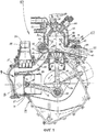
Фиг. 1 - вид в сечении двухтактного одноцилиндрового двигателя согласно изобретению в плоскости, проходящей перпендикулярно оси коленчатого вала, и в которой лежит ось цилиндра;FIG. 1 is a cross-sectional view of a two-stroke single-cylinder engine according to the invention in a plane extending perpendicular to the axis of the crankshaft, and in which the axis of the cylinder lies;
Фиг. 2-8 - схематические и частичные виды, иллюстрирующие положения основных деталей двигателя при разных углах поворота ведущего вала в рамках цикла;FIG. 2-8 are schematic and partial views illustrating the positions of the main engine parts at different angles of rotation of the drive shaft within the cycle;
Фиг. 9 - вид в сечении двигателя с Фиг. 1 в плоскости, проходящей вдоль оси коленчатого вала и оси цилиндра;FIG. 9 is a sectional view of the engine of FIG. 1 in a plane along the axis of the crankshaft and the axis of the cylinder;
Фиг. 10 - вид в поперечном сечении двигателя по плоскости, перпендикулярной оси цилиндра;FIG. 10 is a cross-sectional view of an engine in a plane perpendicular to the axis of the cylinder;
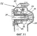
Фиг. 11 - вид в сечении механизма изменения фаз распределительного вала для двигателя с Фиг. 1 согласно одному варианту осуществления изобретения;FIG. 11 is a sectional view of the camshaft phase change mechanism for the engine of FIG. 1 according to one embodiment of the invention;
Фиг. 12 - вид в поперечном сечении трехцилиндрового двигателя согласно другому варианту осуществления изобретения; иFIG. 12 is a cross-sectional view of a three-cylinder engine according to another embodiment of the invention; and
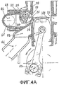
Фиг. 4A - схематичный вид основных деталей двигателя с Фиг. 12 в положении, которое соответствует положению с Фиг. 4, в соответствии с другим вариантом осуществления изобретения.FIG. 4A is a schematic view of the main engine parts of FIG. 12 in the position corresponding to the position of FIG. 4, in accordance with another embodiment of the invention.
НАИЛУЧШИЙ СПОСОБ ОСУЩЕСТВЛЕНИЯ ИЗОБРЕТЕНИЯBEST MODE FOR CARRYING OUT THE INVENTION
Фиг. 1, 9 и 10 показывают одноцилиндровый двигатель новой концепции, обозначенный в целом ссылочной позицией 10, который может применяться, в частности, но не исключительно на электрических или гибридных транспортных средствах.FIG. 1, 9 and 10 show a single-cylinder engine of a new concept, indicated generally by the
Двигатель 10 включает в себя картер 11, состоящий из двух полукартеров 12, 13, и коленчатый вал 14, опирающийся на два подшипника 2, 3 в картере 11. Картер 11 с одной стороны ограничивает цилиндр 18 двигателя с осью A, который содержит совершающий возвратно-поступательное движение поршень 20 двигателя в комплекте с компрессионными кольцами 21 и маслосъемным кольцом 22, размещенным в юбке поршня. Поршень 20 шарнирно соединен с шатуном 15 посредством пальца 19.The
С другой стороны картера 11 выполнен нагнетатель 9 воздуха, который включает в себя цилиндр 23 нагнетателя с осью B, которая перпендикулярна оси A, который содержит совершающий возвратно-поступательное движение поршень 24 нагнетателя в комплекте с компрессионными кольцами 25 и маслосъемным кольцом 26. Поршень 24 нагнетателя шарнирно соединен с шатуном 16 посредством пальца 27.On the other side of the crankcase 11, an air supercharger 9 is made, which includes a
Коленчатый вал 14 имеет шатунную шейку 83, с которой шарнирно соединены шатуны 15, 16 через шариковые подшипники 4, 5. В целях экономии коленчатый вал 14 предпочтительно изготовлен из трех деталей: дух полуосей 14a, 14b и шатунной шейки 83, которая их соединяет (см. Фиг. 9).The
Нагнетатель 9 воздуха, размещенный таким образом, что его ось перпендикулярна оси цилиндра 18 двигателя, обладает преимуществом, состоящим в том, что он балансирует силы первого порядка: составляющая при вращении в ту же сторону может быть сбалансирована противовесом коленчатого вала 14, в то время как составляющая при вращении в противоположную сторону противоположна той, которую создает двигатель и аннулирует ее.An air blower 9, arranged in such a way that its axis is perpendicular to the axis of the
Коренные подшипники 2, 3 коленчатого вала 14 и шариковые подшипники 4, 5 смазываются под давлением маслом, подаваемым посредством насоса 17, размещенного на коленчатом валу 14, причем выбор данного типа преследует своей целью достижение низких уровней шума.The
Цилиндр 23 нагнетателя и цилиндр 18 двигателя соединены главным каналом 32, который сообщается с впускным коллектором 34 посредством группы однонаправленных клапанов с пластинами 37. Главный канал 32 сообщается с внутренней частью цилиндра 18 двигателя посредством множества транзитных окон 28, которые открываются в соответствующих окнах, размещенных непосредственно над поршнем 20, при его нахождении в нижней мертвой точке. Транзитные окна 28, которые в поперечном сечении, по сути, образуют прямоугольник, наклонены вверх, при выходе из главного канала 32 в цилиндр 18, и распределены вокруг последнего (Фиг. 10) за исключением зоны диаметрально противоположной каналу 32, в которой размещается выпускное окно для выпускного канала 33. Окно выпускного канала 33, которое в поперечном сечении так же, по сути, образует прямоугольник, выполнено непосредственно над поршнем, при его нахождении в нижней мертвой точке.The
Главный канал 32 сообщается с цилиндром 18 через вспомогательный канал 29, который ответвляет поток, восходящий к транзитным окнам 28, при этом он наклонен вверх и выходит в цилиндр 18 на уровне выше уровня транзитных каналов 28 и выпускного канала 33. Вспомогательный канал 29 служит как для наддува, так и разгрузки.The
Вспомогательный канал 29 пересекается с цилиндрическим посадочным местом 38, выполненным тангенциально к стенке цилиндра 18, в котором размещается поворотный клапан 30, вращающийся с той же скоростью, что коленчатый вал 14, но в противоположном направлении и опирающийся на два шариковых подшипника 85, 86; при этом поворотный клапан 30 цилиндрический герметично соединен с посадочным местом 38, чтобы перекрывать канал 29, однако имеет желоб 31, выполненный таким образом, чтобы открывать канал 29 наддува при совмещении с ним.The
Искривленная форма поворотного клапана 30 вызывает статический и динамический дисбаланс, который может быть полностью сбалансирован при помощи соответствующих облегчений 77, выполненных на упомянутом клапане, в зоне, противоположной той, что обращена к каналу 29.The curved shape of the
Несмотря на точность сопряжения между поворотным клапаном 30 и посадочным местом 38, для того чтобы исключить вероятность протечки через соединение, по сторонам желоба 31 клапана могут быть выполнены две проточки для размещения в них уплотнительных колец 78, которые статично взаимодействуют, посредством организации упругого предварительного натяга с поверхностью посадочного места 38.Despite the accuracy of the mating between the
Как уже упомянуто, из-за своей особой конфигурации, клапан 30 должен вращаться в направлении, противоположном вращению двигателя. Привод размещается с внешней стороны картера 11, как показано на Фиг. 9, внутри картера 39 и крышки 40 на стороне, на которой так же размещается масленый насос 17. Цепь 42 передает движение от звездочки 43, посаженной на шпонке на коленчатом валу 14, к звездочке 44, которая свободно вращается на промежуточной оси 41; пара шестерен 45 и 46 используются для того, чтобы обратить движение, причем первая выполнена совместно с цепной звездочкой 44, а другая посажена на шпонку на оси поворотного клапана 30.As already mentioned, due to its particular configuration, the
Данный привод, полностью смазываемый маслом двигателя, так же приводит в действие бензонасос 47 высокого давления посредством толкателя 48, взаимодействующего с подшипником 49, который размещен на эксцентричном посадочном месте 59, выполненном на шестерне 46, которая в свою очередь посажена на шпонку на оси поворотного клапана 30.This drive, completely lubricated by engine oil, also drives a high-pressure gas pump 47 by means of a
Фиг. 1, 9 и 10 показывают упрощенный вариант клапана 30, разработанного для функционирования двигателя 10 только в варианте с наддувом, вследствие чего не предусмотрено исключение канала 29.FIG. 1, 9 and 10 show a simplified version of the
Данный вариант двигателя 10, в частности, пригоден для использования в качестве электродвигателя-генератора для зарядки батарей электрических транспортных средств («устройства увеличения дальности поездки»). В данном случае электрогенератор размещается с одной стороны двигателя, как показано на Фиг. 9, при этом ротор 88 посажен на шпонку на коленчатом валу 14, а статор 81 вставляется в посадочное место полукартера 12 двигателя.This embodiment of the
На цилиндре 18 двигателя размещена головка 74, которая ограничивает камеру 7 сгорания и в которой находится форсунка 58, установленная для осуществления непосредственного впрыска в направлении, по существу противоположном потоку продувки, и свеча 36.On the
Выпускной канал 33 пересекает цилиндрическое окно 50, в котором размещается клапан 51 для управления полезным сечением выпускного канала. Такое устройство служит для уменьшения мощности двигателя, тем самым способствуя сохранению продуктов сгорания внутри цилиндра, стабилизируя наполнение, улучшая равномерность двигателя при низкой загрузке, в частности на холостом ходу, явно сокращая большую часть циклической неравномерности двигателя, обеспечивая при этом преимущества в отношении выбросов и расхода.The
Клапан 51 встроен в группу 62 выпускного коллектора, прикрепленного к цилиндру 18 посредством болтов 69, что явно показано на Фиг. 1 и 10. Группа 62 включает в себя коллектор 60 с внутренней полостью, которая служит продолжением выпускного канала 33, соединяя его с выпускной системой 61, и содержит клапан 51.Valve 51 is integrated into
Клапан 51 состоит из профилированного элемента с частью 79 цилиндрической поверхности, которая взаимодействует с посадочным местом 50, выполненным в цилиндре 18. Этот элемент закреплен болтом 89 на валу 90 и имеет форму, которая способствует отводу тепла. По обе стороны клапана 51 в начале цилиндрической части вала 90 предусмотрены посадочные места для уплотнительных колец 91, которые установлены с предварительным натягом в цилиндрических посадочных местах 92 корпуса, образуя эффективный барьер для утечки газа. На концах вала 90 предусмотрены сальники 93 и опорные подшипники 94, 95.The valve 51 consists of a profiled element with a
Коллектор 60 имеет широкую камеру 63 для охлаждающего вещества, чьи большие поверхности теплоотдачи могут предотвратить перегрев группы. С одной стороны вала 90 расположен датчик 64 положения, а с другой - двухходовой электромотор 65 для изменения положения клапана 51.The
Данное устройство управляется электрически, и в данном типе двигателя оно должно быть объединено с положением дроссельной заслонки 87, размещенной во впускном коллекторе 34.This device is electrically controlled, and in this type of engine it must be combined with the position of the
Двигатель 10 выполнен с водяным охлаждением, которое осуществляется центробежным насосом 70, который находится в закрывающей крышке электрогенератора, в которой предварительно смонтировано лопастное колесо, приводимое коленчатым валом 14. Охлаждающее вещество отправляется насосом 70 в камеру 71, выполненную в полу-картере 12 двигателя, в котором также размещается статор 81, для охлаждения электрогенератора; отсюда оно выходит через окно 72 и попадает в цилиндр, где оно находит канал 73, который направляет охлаждающее вещество таким образом, что оно омывает наружную поверхность выпускного канала 33 и камеры 63 охлаждения группы 62, в которой размещается клапан 51, а затем оно переходит в головку 74 и выходит из термостата 75, чтобы попасть в радиатор (не показано).The
Система также оборудована контуром, по которому жидкость циркулирует внутри двигателя во время фазы прогрева, когда термостат закрыт.The system is also equipped with a circuit through which fluid circulates inside the engine during the warm-up phase when the thermostat is closed.
Функционирование двигателя 10 описывается, начиная с положения на Фиг. 2, при котором поршень 20 двигателя находится в нижней мертвой точке, при этом транзитное окно и выпускное окно полностью открыты, в то время как положение поршня 24 нагнетателя соответствует фазе полного сжатия, и вследствие этого в цилиндр 18 двигателя через главный канал 32 и транзитное окно 28 выпускается воздух, выполняя фазу продувки, чтобы вытолкнуть продукты сгорания. Желоб 31 поворотного клапана готов открыть канал 29 наддува.The operation of the
Фиг. 3 показывает поршень 20 двигателя, который начал подъем к ВМТ, уменьшая транзитное окно и выпускное окно, в то время как при подъеме поворотный клапан 30 быстро открывает канал 29 наддува и поршень 24 нагнетателя, превысив максимальную скорость.FIG. 3 shows the
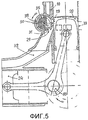
Фиг. 4 показывает поршень 20 двигателя, который закрыл транзитные окна каналов 28, тем самым завершив фазу продувки, и готовится закрыть выпускной канал 33, в то время как желоб 31 поворотного клапана 30 оставляет канал 29 наддува полностью открытым, при этом на конечной стадии подъема поршня 24 нагнетателя в него подается воздух и готовится начало впрыска топлива через форсунку 58.FIG. 4 shows the
Фиг. 5 вновь показывает открытый канал 29 наддува, когда поршень 24 нагнетателя достиг своей ВМТ, и поршень 20 двигателя закрывает окно канала 29 наддува, тем самым завершая фазу наполнения цилиндра, и начинается смешивание воздуха с топливом, которое впрыскивается форсункой 58 против потока продувки. Так же сразу, как только поршень 20 двигателя закрывает канал 29 наддува, в то время как поршень 24 нагнетателя воздуха начинает обратное движение и перемещается по направлению к нижней мертвой точке, начинается фаза впуска с помощью группы клапанов с однонаправленными пластинами 37, которые позволяют воздуху попасть в канал 32; между тем, поршень 20 двигателя достигает момента зажигания и прекращается впрыск топлива, за которыми следуют зажигание и возгорание.FIG. 5 again shows the
Фиг. 6 показывает поршень 20 двигателя, который опускается из ВМТ благодаря горению смеси, ранее сжатой и воспламененной свечой 36 в камере сгорания, при этом поршень начинает открывать окно канала 29 наддува (перед выпуском), который тем не менее закрыт цилиндрической поверхностью поворотного клапана 30.FIG. 6 shows the
При необходимости на поворотном клапане 30 может быть организован канал 35 (как показано на чертеже), приемлемой толщины и длины, которые позволят части сгоревших газов перетечь в главный канал 32, до того как будет открыто окно в выпускной канал 33, тем самым обеспечивая, при необходимости, рециркуляцию (EGR) определенному объему сгоревших газов, в то время как поршень 24 нагнетателя достигает своей нижней мертвой точки и завершает свою фазу впуска.If necessary, a channel 35 (as shown in the drawing) can be arranged on the
Фиг. 7 показывает поршень 20 двигателя, который начал открывать окно выпускного канала 33, через который отработавшие газы начнут вытекать под давлением. В то же время поршень 24 нагнетателя, который на 90º опережает поршень 20 двигателя, завершил исходную часть своего сжатия, отправляя воздух в главный канал 32, а затем в цилиндр через транзитные окна 28, чтобы вытолкнуть продукты сгорания собственно предыдущего сгорания, как только очередная часть движения вниз вызовет открытие окон 28, при этом поршень 24 нагнетателя находится в фазе подачи, как показано на Фиг. 8.FIG. 7 shows a
Это завершает полный цикл, который повторяется каждый оборот коленчатого вала.This completes the full cycle, which is repeated every revolution of the crankshaft.
На Фиг. 2-8 поворотный клапан 30 всегда находится в положении наддува.In FIG. 2-8, the
Если не требуется, чтобы двигатель развивал максимальную мощность, то клапан 30 может быть перемещен в положение, повернутое на 90°, в направлении, противоположном вращению, используя преобразователь 76 фаз, как показано на Фиг. 11, связанный с концом оси, которая перемещает поворотный клапан.If it is not required that the engine develops maximum power, then the
Промежуточная шестерня 52 (которая заменяет шестерню 46 в варианте осуществления с Фиг. 1, 9 и 10) устанавливается на клапан 30 и приводится коленчатым валом 14 посредством шестерни, цепи или иным образом. Другой элемент 53 закрепляется на конце цилиндрической части клапана 30, с которой он надлежащим образом совмещен по фазе посредством шарика 54. Соединение между шестерней 52 и элементом 53 выполнено при помощи короткой втулки 55 с внутренними спиральными желобами, которые выполнены симметрично, и наклонены противоположно друг другу относительно проточки в центре. Короткая втулка 55 соединена под углом с шестерней 52 и элементом 53 посредством шариков 56, которые размещаются в соответствующих канавках в шестерне 52 и элементе 53, который объединен с клапаном 30 и которые могут перемещаться по спиральным желобам короткой втулки 55.The intermediate gear 52 (which replaces gear 46 in the embodiment of FIGS. 1, 9 and 10) is mounted on the
Короткая втулка 55 может перемещаться в осевом направлении при помощи вилки 57, приводимой в действие электронно-управляемым соленоидом (не показан). При осевом перемещении короткой втулки 55, сферы 56 заставляют шестерню 52 и другой элемент 53 переместиться в другое взаимное положение, тем самым меняя фазы.The
Вновь рассматривая схематические Фиг. 3-8, в отношении того, какое положение поворотный клапан 30 занимает при условии частичной нагрузки (указанной штриховой линией), отмечено, что на Фиг. 4, которая сначала показывала канал 29 наддува полностью открытым, теперь показано, что канал закрыт, тем не менее при этом при необходимости доступна опция, связанная с описанной на Фиг. 6 и 7 возможностью организации канала 35 на поверхности клапана для рециркуляции отработавших газов при полной нагрузке, которая тем самым создает преемственность с сечением, которое применяется для режима с сокращенным выбросом газа, который, если необходимо, конечно будет ниже, чем тот, который получается при полной мощности, имея ввиду, что мощность уменьшается посредством закрытия клапана 51 в выпускном канале, который уже наполнен изрядным количеством отработавших газов.Referring again to the schematic FIG. 3-8, regarding the position of the
Вкратце можно сказать, что при помощи данного устройство можно отдельно калибровать канал 35, который замыкает отработавшие газы, в зависимости от нагрузки на двигатель.In short, we can say that using this device, you can separately calibrate the
Поворотный клапан 30 среди множества возложенных на него функций также включает в себя функцию по разгрузке для уменьшения момента сопротивления при пуске двигателя, как показано на Фиг. 5; при этом необходимо принимать во внимание, что эффективность нагнетателя воздуха уменьшается на скорости пуска, вследствие этого невозможно нагнетать воздух через вспомогательный канал. При положении поворотного клапана в режиме наддува поршень 20 двигателя начинает фазу сжатия не после того как закрыт выпускной канал 33, а после того как закрыто окно вспомогательного канала 29; вследствие этого произойдет задержка сжатия, двойное преимущество которой состоит в том, что когда плечо рычага, определяемое радиусом кривошипа, соответствует максимуму (как в положении на Фиг. 5), то давление внутри цилиндра является низким, вследствие чего является малым сопротивление. Затем давление нарастает, когда поршень 20 двигателя достигает ВМТ, при этом в этой точке плечо рычага уменьшается, что приводит к тому, что в ней будет очень маленький момент сопротивления.The
Уменьшение момента сопротивления при пуске, в частности, является преимуществом в вариантах применения, в которых требуется частый повторный пуск двигателя, например, в стартстопных системах.Reducing the moment of resistance during start-up, in particular, is an advantage in applications that require frequent restarting of the engine, for example, in start-stop systems.
Фиг. 12 иллюстрирует второй вариант осуществления данного изобретения, который заключается в трехцилиндровом двигателе, который целиком обозначен ссылочной позицией 100 и, в частности, пригоден в качестве тягового устройства в автомобильной отрасли.FIG. 12 illustrates a second embodiment of the present invention, which consists of a three-cylinder engine, which is completely indicated by the
При описании Фиг. 12, для удобства, элементы, которые выполняют те же функции, что уже описаны для одноцилиндрового двигателя, обозначены точно такими же ссылочными позициями.In the description of FIG. 12, for convenience, elements that perform the same functions as those already described for a single-cylinder engine are denoted by exactly the same reference numerals.
Для подачи воздуха в двигатель 100 предпочтительно использовать нагнетатель с постоянной подачей, совместимый с характеристиками двигателя, вместо поршневого нагнетателя как в одноцилиндровых двигателях, так как если рабочий объем разбит, то данное решение более не имеет преимуществ как в плане затрат, так и размера.To supply air to the
Чтобы уменьшить поток воздуха при частичных нагрузках, может использоваться привод двигатель-нагнетатель с непрерывным преобразователем скорости, или упрощенное решение при помощи ступенчатого привода и воздушной заслонки на впуске нагнетателя с электронным управлением, которая заменяет функцию дроссельной заслонки. Управление данным устройством должно осуществляться совместно с уменьшением выпускного окна, которое главным образом отвечает за управление частичными нагрузками.To reduce the air flow at partial loads, a continuous-speed drive motor-supercharger drive can be used, or a simplified solution using a step-by-step drive and an electronically controlled air inlet of the supercharger inlet that replaces the throttle function. This device should be controlled in conjunction with a reduction in the outlet window, which is primarily responsible for managing partial loads.
Нагнетатель воздуха (не показан) осуществляет подачу в двигатель через впускное окно 66, которое сообщается с камерой 82, которая разветвляется на транзитные окна 28; тем не менее двигатель 100 продолжает функционировать таким же образом, как уже было описано для одноцилиндрового варианта.An air blower (not shown) delivers to the engine through an
Фиг. 12 показывает сечение на высоте транзитных окон 28 как по оси поворотного клапана 30, так и по оси 90 дроссельных заслонок 51 выпускных каналов 33. В отличие от одноцилиндрового варианта в данном трехцилиндровом варианте, поскольку требуется как функционирование с наддувом, так и с частичной рециркуляцией газа, то поворотный клапан 30 имеет такую форму, чтобы выполнять все функции, которыми может управлять данное устройство и которые уже были описаны в одноцилиндровом варианте. Вкратце, поворотный клапан 30 имеет желоба 31 для управления соответствующими каналами 29 наддува, желоба 77 для балансировки клапана 30 и каналы 35 с переменным сечением для управления количеством участвующего в рециркуляции отработавшего газа при различных условиях работы двигателя.FIG. 12 shows a cross section at the height of the
Даже в режиме наддува в двигателе 100, как уже объяснено для одноцилиндрового двигателя, т.е. как показано на Фиг. 4, во время подъема поршня 20 двигателя транзитные окна 28 не закрыты, желоб 31 оставляет канал 29 открытым для наддува; и это может быть полезным для увеличения наполнения при использовании альтернативных высокооктановых видов топлива, как впрочем и для задержки сжатия при пуске, тем самым сокращая работу, расходуемую для данной функции, как объяснено для одноцилиндрового варианта.Even in boost mode in
Другой способ подачи воздуха для данного многоцилиндрового варианта может соответствовать тому, что показано на Фиг. 4A, где присутствует две магистрали подачи воздуха: главная магистраль 66 низкого давления, которая снабжает транзитные окна 28 через камеру 82, и другой ответвляющийся или отдельный канал 84, выполненный в коллекторе 67, который присоединен к цилиндру 18 посредством болтов 68, и осуществляющий подачу с более высоким давлением, который сообщается с каналом 29. В канале 29 выполнен поворотный клапан 30 с предусмотренным желобом 31 для продолжения подачи в закрытый цилиндр 18 двигателя через канал 29 наддува. Такая система направлена на достижение более высокой удельной мощности с отличной производительностью в диапазоне от средней до низкой мощности применительно к подаче с низким давлением.Another air supply method for a given multi-cylinder embodiment may correspond to that shown in FIG. 4A, where there are two air supply lines: a main low-
Также предполагается, что на конце клапана 30 будет установлен вариатор 76 фаз, перемещение которого передается шестерне 52, аналогично тому, как описано со ссылкой на Фиг. 11.It is also assumed that a phase variator 76 will be installed at the end of
Впрочем на данном двигателе мощность уменьшается главным образом посредством перекрытия выпускных каналов 33, аналогично тому и с теми же преимуществами, которые уже описаны в отношении одноцилиндрового варианта. В группе 62 выпускного коллектора клапаны 51 с цилиндрической частью (не показаны на Фиг. 12) работают в посадочных местах 50, выполненных в блоке цилиндров 80, и прикреплены к оси 90 соответствующей формы с сальниками 93 и опорными подшипниками 94 и 95 по концам. Клапанный блок размещен в коллекторе 60, омываемом охлаждающей жидкостью, который после установки на цилиндр соединяет выпускной канал 33 с выпускной системой (не показана). По обоим концам вала 90 предусмотрен датчик 64 положения и двухходовой электромотор 65 для изменения положения дроссельной заслонки 51.However, on this engine, power is reduced mainly by blocking the
При рассмотрении характеристик двигателей 10 и 100, созданных в соответствии с данным изобретением, очевидны следующие преимущества.When considering the characteristics of the
Во-первых, при помощи многофункционального клапана 30 можно просто и эффективно управлять наддувом и уменьшать момент сопротивления при запуске, посредством разгрузки цилиндра. Предпочтительно, клапан также может управлять рециркуляцией отработавших газов.Firstly, with the help of the
Дополнительные преимущества, обеспечиваемые этими двигателями, созданными в соответствии с данным изобретением, являются следующими:Additional benefits provided by these engines created in accordance with this invention are as follows:
- исключаются потери свежей смеси при выпуске из-за продувки воздухом и непосредственного впрыска топлива в цилиндр при помощи форсунки, размещенной в головке и направленной в направлении противоположном потоку продувки;- eliminates the loss of fresh mixture during the release due to air purging and direct injection of fuel into the cylinder by means of a nozzle located in the head and directed in the direction opposite to the purge flow;
- продувка является более эффективной по сравнению с обычными двухтактными двигателями;- purge is more efficient than conventional two-stroke engines;
- возможно дозирование правильного объема отработавших газов, участвующих в рециркуляции;- dosing of the correct volume of exhaust gases involved in the recirculation is possible;
- исключается утечки масла для смазки с вытекающими из этого преимуществами, связанными с сокращением выброса загрязняющих веществ, уменьшением нагара и последующего сокращения работ по обслуживанию;- eliminates the leakage of oil for lubrication with the ensuing benefits associated with reduced emissions of pollutants, reduced carbon deposits and subsequent reduction in maintenance work;
- возможно увеличение степени сжатия, тем самым получают более высокое среднее давление для цикла; причем это возможно при помощи испарения бензина в цилиндре и при помощи косвенного охлаждения обогащаемого воздуха; при этом преимущество сохраняется даже при частичной мощности благодаря небольшой камере сгорания;- it is possible to increase the degree of compression, thereby obtaining a higher average pressure for the cycle; moreover, this is possible by evaporating gasoline in the cylinder and by indirect cooling of the enriched air; while the advantage is maintained even at partial power due to the small combustion chamber;
- возможность использования альтернативных видов топлива.- the possibility of using alternative fuels.
Приведенные выше преимущества сопровождаются теми, которые типичны для двухтактных двигателей по сравнению с четырехтактными двигателями:The above advantages are accompanied by those typical of two-stroke engines compared to four-stroke engines:
- меньше вес и меньше габаритные размеры;- less weight and less overall dimensions;
- меньше удельный расход при количественном управлении газом;- less specific consumption for quantitative gas management;
- выше равномерность момента благодаря тому, что полезных циклов вдвое больше, чем тех же циклов при выполнении четырехтактным двигателем за тот же интервал времени;- higher uniformity of the moment due to the fact that there are twice as many useful cycles as the same cycles when a four-stroke engine is running for the same time interval;
- уменьшаются механические нагрузки на шатуны, поскольку при тех же моментах, среднее эффективное давление цилиндра составляет половину значения, которое будет у четырехтактного двигателя;- reduced mechanical stress on the connecting rods, because at the same moments, the average effective pressure of the cylinder is half the value that a four-stroke engine will have;
- можно использовать высокоэффективные камеры сгорания благодаря отсутствию клапанов.- You can use highly efficient combustion chambers due to the lack of valves.
В заключении очевидно, что описанные двигатели 10, 100 могут быть модифицированы или изменены, не выходя за рамки объема изобретения, определяемого формулой изобретения.In conclusion, it is obvious that the described
Claims (14)
Applications Claiming Priority (1)
| Application Number | Priority Date | Filing Date | Title |
|---|---|---|---|
| PCT/IT2010/000057 WO2011101878A1 (en) | 2010-02-17 | 2010-02-17 | Two-stroke engine with low consumption and low emissions |
Publications (2)
| Publication Number | Publication Date |
|---|---|
| RU2012139818A RU2012139818A (en) | 2014-03-27 |
| RU2524313C2 true RU2524313C2 (en) | 2014-07-27 |
Family
ID=43128209
Family Applications (1)
| Application Number | Title | Priority Date | Filing Date |
|---|---|---|---|
| RU2012139818/06A RU2524313C2 (en) | 2010-02-17 | 2010-02-17 | Two-stroke low-fuel-consumption low-emission ice |
Country Status (10)
| Country | Link |
|---|---|
| US (1) | US8578895B2 (en) |
| EP (1) | EP2536932B1 (en) |
| JP (1) | JP5478741B2 (en) |
| KR (1) | KR101642172B1 (en) |
| CN (1) | CN102892993B (en) |
| BR (1) | BR112012020479B1 (en) |
| ES (1) | ES2474151T3 (en) |
| IN (1) | IN2012MN02006A (en) |
| RU (1) | RU2524313C2 (en) |
| WO (1) | WO2011101878A1 (en) |
Families Citing this family (6)
| Publication number | Priority date | Publication date | Assignee | Title |
|---|---|---|---|---|
| FR3027626B1 (en) | 2014-10-24 | 2018-01-05 | Renault S.A.S | EXHAUST SYSTEM FOR INTERNAL COMBUSTION ENGINE |
| US10648399B2 (en) * | 2017-10-03 | 2020-05-12 | Polaris Industries Inc. | Exhaust-tuning port and timing and combustion chamber shape |
| EP3714137B1 (en) | 2017-11-24 | 2021-12-29 | BRP-Rotax GmbH & Co. KG | Exhaust valve assembly for a two-stroke internal combustion engine |
| ES2923588T3 (en) * | 2018-07-11 | 2022-09-28 | Hypertec Solution S R L | Two-stroke internal combustion engine and relative drive method |
| US11313409B1 (en) * | 2019-12-19 | 2022-04-26 | Brunswick Corporation | Crankshaft and cranktrain for internal combustion engine |
| CZ308792B6 (en) | 2020-04-01 | 2021-05-19 | Marek Ing. Žák | Two-stroke combustion engine |
Citations (6)
| Publication number | Priority date | Publication date | Assignee | Title |
|---|---|---|---|---|
| SU8909A1 (en) * | 1927-01-17 | 1929-04-30 | Крейссле Г. | Two stroke internal combustion engine |
| US2609802A (en) * | 1948-10-01 | 1952-09-09 | Schnurle | Two-stroke cycle internal-combustion engine |
| SU130420A1 (en) * | 1959-11-13 | 1959-11-30 | Гласьер Метал Компани Лимитед | Lubrication method of sliding bearings operating under cyclic loading |
| SU1071233A3 (en) * | 1978-08-14 | 1984-01-30 | Хилти А.Г. (Фирма) | Hammer drill |
| RU2038493C1 (en) * | 1992-06-04 | 1995-06-27 | Дьяченко Василий Григорьевич | Internal combustion engine |
| RU2231657C2 (en) * | 2002-08-07 | 2004-06-27 | Каменев Юрий Георгиевич | Two-stroke internal combustion engine |
Family Cites Families (19)
| Publication number | Priority date | Publication date | Assignee | Title |
|---|---|---|---|---|
| US2542707A (en) * | 1948-03-15 | 1951-02-20 | Ricardo | Internal-combustion engine operating on the two-stroke cycle with compression ignition |
| US4899698A (en) * | 1987-10-30 | 1990-02-13 | Georges Thery | Combustion chamber for two-stroke reciprocating engine, and and engine making use thereof |
| US5088285A (en) * | 1989-06-05 | 1992-02-18 | Wagner & Middlebrook | Internal combustion engine |
| SE468099B (en) * | 1990-11-06 | 1992-11-02 | Electrolux Ab | TWO TASK COMBUSTION ENGINE WITH CHARGING UNIT |
| US5299537A (en) * | 1992-03-11 | 1994-04-05 | Thompson Ransom S | Metered induction two cycle engine |
| RU2066379C1 (en) | 1994-07-13 | 1996-09-10 | Юрий Николаевич Скрипов | Two-stroke internal combustion engine |
| KR0148429B1 (en) * | 1994-11-23 | 1998-11-02 | 조래승 | Hybrid engine |
| US5771849A (en) * | 1995-09-15 | 1998-06-30 | Hamy; Norbert | Internal combustion engine with crankcase pressure barrier |
| JP3765335B2 (en) * | 1995-09-19 | 2006-04-12 | 本田技研工業株式会社 | 2-cycle internal combustion engine |
| AU704849B2 (en) * | 1995-09-19 | 1999-05-06 | Honda Giken Kogyo Kabushiki Kaisha | Two-cycle internal combustion engine |
| TW358849B (en) * | 1996-09-19 | 1999-05-21 | Honda Motor Co Ltd | 2-stroke internal combustion engine |
| JP3836945B2 (en) * | 1997-05-23 | 2006-10-25 | 本田技研工業株式会社 | Exhaust control valve structure for 2-cycle engine |
| FR2788307B1 (en) * | 1999-01-07 | 2001-03-09 | Daniel Drecq | TWO- OR FOUR-TIME INTERNAL COMBUSTION COMPRESSOR ENGINE |
| US6748909B2 (en) * | 1999-01-07 | 2004-06-15 | Daniel Drecq | Internal combustion engine driving a compressor |
| JP2001082157A (en) * | 1999-03-23 | 2001-03-27 | Kayseven Co Ltd | Two-cycle internal combustion engine and scavenging pump therefor |
| US6216649B1 (en) * | 1999-05-19 | 2001-04-17 | Adventech Corporation | Low emission two-cycle internal combustion engine for powering a portable tool |
| US6263841B1 (en) * | 1999-11-02 | 2001-07-24 | John Herbert Beveridge | Two stroke engine having reduced emissions |
| AR047546A1 (en) * | 2004-11-17 | 2006-01-25 | Juana Elisabeth Fabrega | TWO-TIMED MOTOR CONTROLLED SELF-POWER |
| US7428886B1 (en) * | 2007-01-26 | 2008-09-30 | Minculescu Mihai C | Two-cycle engine and compressor |
-
2010
- 2010-02-17 BR BR112012020479-3A patent/BR112012020479B1/en active IP Right Grant
- 2010-02-17 EP EP10711737.6A patent/EP2536932B1/en active Active
- 2010-02-17 JP JP2012553446A patent/JP5478741B2/en active Active
- 2010-02-17 ES ES10711737.6T patent/ES2474151T3/en active Active
- 2010-02-17 RU RU2012139818/06A patent/RU2524313C2/en active
- 2010-02-17 KR KR1020127024300A patent/KR101642172B1/en active IP Right Grant
- 2010-02-17 CN CN201080064361.2A patent/CN102892993B/en active Active
- 2010-02-17 US US13/577,203 patent/US8578895B2/en active Active
- 2010-02-17 WO PCT/IT2010/000057 patent/WO2011101878A1/en active Application Filing
-
2012
- 2012-08-21 IN IN2006MUN2012 patent/IN2012MN02006A/en unknown
Patent Citations (6)
| Publication number | Priority date | Publication date | Assignee | Title |
|---|---|---|---|---|
| SU8909A1 (en) * | 1927-01-17 | 1929-04-30 | Крейссле Г. | Two stroke internal combustion engine |
| US2609802A (en) * | 1948-10-01 | 1952-09-09 | Schnurle | Two-stroke cycle internal-combustion engine |
| SU130420A1 (en) * | 1959-11-13 | 1959-11-30 | Гласьер Метал Компани Лимитед | Lubrication method of sliding bearings operating under cyclic loading |
| SU1071233A3 (en) * | 1978-08-14 | 1984-01-30 | Хилти А.Г. (Фирма) | Hammer drill |
| RU2038493C1 (en) * | 1992-06-04 | 1995-06-27 | Дьяченко Василий Григорьевич | Internal combustion engine |
| RU2231657C2 (en) * | 2002-08-07 | 2004-06-27 | Каменев Юрий Георгиевич | Two-stroke internal combustion engine |
Also Published As
| Publication number | Publication date |
|---|---|
| KR20120129979A (en) | 2012-11-28 |
| EP2536932B1 (en) | 2014-03-19 |
| BR112012020479A2 (en) | 2020-08-25 |
| JP5478741B2 (en) | 2014-04-23 |
| KR101642172B1 (en) | 2016-07-29 |
| BR112012020479B1 (en) | 2021-06-01 |
| RU2012139818A (en) | 2014-03-27 |
| CN102892993A (en) | 2013-01-23 |
| ES2474151T3 (en) | 2014-07-08 |
| EP2536932A1 (en) | 2012-12-26 |
| US8578895B2 (en) | 2013-11-12 |
| IN2012MN02006A (en) | 2015-06-12 |
| WO2011101878A1 (en) | 2011-08-25 |
| JP2013519839A (en) | 2013-05-30 |
| US20120304972A1 (en) | 2012-12-06 |
| CN102892993B (en) | 2014-12-10 |
Similar Documents
| Publication | Publication Date | Title |
|---|---|---|
| KR960007104B1 (en) | Engine using compressed air | |
| JP3016485B2 (en) | Reciprocating 2-cycle internal combustion engine without crank | |
| CA2468169C (en) | Internal combustion engine | |
| RU2524313C2 (en) | Two-stroke low-fuel-consumption low-emission ice | |
| JP2005503512A (en) | Piston reciprocating engine with rotary cylinder | |
| US8613269B2 (en) | Internal combustion engine with direct air injection | |
| US4907544A (en) | Turbocharged two-stroke internal combustion engine with four-stroke capability | |
| US20100192878A1 (en) | Air hybrid engine with dual chamber cylinder | |
| US20120222658A1 (en) | Internal combustion engine with dual-chamber cylinder | |
| US5970924A (en) | Arc-piston engine | |
| US20160025002A1 (en) | Improved opposed piston engine | |
| RU2361093C2 (en) | Internal combustion engine | |
| US6513475B2 (en) | Rotary valve internal combustion engine | |
| US6021746A (en) | arc-piston engine | |
| US4834032A (en) | Two-stroke cycle engine and pump having three-stroke cycle effect | |
| CA2619915C (en) | Two stroke engine with regular lubrication system | |
| JPH0733776B2 (en) | Rotary internal combustion engine | |
| US20170009617A1 (en) | Sleeve valve engine | |
| EP4248073A1 (en) | An internal combustion engine system | |
| RU2246631C2 (en) | Turbopiston engine | |
| WO2023215126A1 (en) | Separate compressor arrangements for engines | |
| WO2019211371A1 (en) | Engine with cooperating pistons based on a two-stroke cycle | |
| GB2144801A (en) | Reciprocating-piston fuel-injection internal-combustion engine | |
| WO2014027214A1 (en) | Internal combustion and method for operation of that | |
| RO109115B1 (en) | Internal combustion engine |