RU2521905C2 - Upper reach bath for gutter section and gutter section fitted by such bath - Google Patents
Upper reach bath for gutter section and gutter section fitted by such bath Download PDFInfo
- Publication number
- RU2521905C2 RU2521905C2 RU2011154041/11A RU2011154041A RU2521905C2 RU 2521905 C2 RU2521905 C2 RU 2521905C2 RU 2011154041/11 A RU2011154041/11 A RU 2011154041/11A RU 2011154041 A RU2011154041 A RU 2011154041A RU 2521905 C2 RU2521905 C2 RU 2521905C2
- Authority
- RU
- Russia
- Prior art keywords
- bath
- chamfer
- bevel
- upper branch
- end edges
- Prior art date
Links
- 230000007704 transition Effects 0.000 claims abstract description 9
- 238000007689 inspection Methods 0.000 claims description 7
- 239000002184 metal Substances 0.000 claims description 5
- 238000005065 mining Methods 0.000 claims description 5
- 239000003245 coal Substances 0.000 abstract description 13
- 230000000694 effects Effects 0.000 abstract description 4
- 239000000126 substance Substances 0.000 abstract 1
- 238000004140 cleaning Methods 0.000 description 3
- 238000006073 displacement reaction Methods 0.000 description 2
- 238000009825 accumulation Methods 0.000 description 1
- 230000009471 action Effects 0.000 description 1
- 230000002411 adverse Effects 0.000 description 1
- 230000004888 barrier function Effects 0.000 description 1
- 230000000903 blocking effect Effects 0.000 description 1
- 230000003116 impacting effect Effects 0.000 description 1
- 230000003993 interaction Effects 0.000 description 1
- 230000004048 modification Effects 0.000 description 1
- 238000012986 modification Methods 0.000 description 1
- 230000035515 penetration Effects 0.000 description 1
- 230000002035 prolonged effect Effects 0.000 description 1
- 230000008439 repair process Effects 0.000 description 1
- 230000000284 resting effect Effects 0.000 description 1
Images


Classifications
-
- B—PERFORMING OPERATIONS; TRANSPORTING
- B65—CONVEYING; PACKING; STORING; HANDLING THIN OR FILAMENTARY MATERIAL
- B65G—TRANSPORT OR STORAGE DEVICES, e.g. CONVEYORS FOR LOADING OR TIPPING, SHOP CONVEYOR SYSTEMS OR PNEUMATIC TUBE CONVEYORS
- B65G19/00—Conveyors comprising an impeller or a series of impellers carried by an endless traction element and arranged to move articles or materials over a supporting surface or underlying material, e.g. endless scraper conveyors
- B65G19/18—Details
- B65G19/28—Troughs, channels, or conduits
- B65G19/285—Troughs, channels, or conduits with detachable or replaceable parts, e.g. replaceable wear channels
-
- B—PERFORMING OPERATIONS; TRANSPORTING
- B65—CONVEYING; PACKING; STORING; HANDLING THIN OR FILAMENTARY MATERIAL
- B65G—TRANSPORT OR STORAGE DEVICES, e.g. CONVEYORS FOR LOADING OR TIPPING, SHOP CONVEYOR SYSTEMS OR PNEUMATIC TUBE CONVEYORS
- B65G19/00—Conveyors comprising an impeller or a series of impellers carried by an endless traction element and arranged to move articles or materials over a supporting surface or underlying material, e.g. endless scraper conveyors
- B65G19/18—Details
- B65G19/28—Troughs, channels, or conduits
- B65G19/287—Coupling means for trough sections
-
- E—FIXED CONSTRUCTIONS
- E21—EARTH OR ROCK DRILLING; MINING
- E21F—SAFETY DEVICES, TRANSPORT, FILLING-UP, RESCUE, VENTILATION, OR DRAINING IN OR OF MINES OR TUNNELS
- E21F13/00—Transport specially adapted to underground conditions
- E21F13/06—Transport of mined material at or adjacent to the working face
- E21F13/066—Scraper chain conveyors
Landscapes
- Engineering & Computer Science (AREA)
- Mechanical Engineering (AREA)
- Mining & Mineral Resources (AREA)
- Life Sciences & Earth Sciences (AREA)
- General Life Sciences & Earth Sciences (AREA)
- Geochemistry & Mineralogy (AREA)
- Geology (AREA)
- Laying Of Electric Cables Or Lines Outside (AREA)
- Pusher Or Impeller Conveyors (AREA)
- Chain Conveyers (AREA)
- Bathtubs, Showers, And Their Attachments (AREA)
- Chutes (AREA)
- Solid Fuels And Fuel-Associated Substances (AREA)
Abstract
Description
Изобретение касается ванны верхней ветви для секции желоба цепного скребкового конвейера, в частности забойного конвейера, применяемого в горных работах, содержащей два боковых профиля и соединяющее эти боковые профили дно ванны, у которого имеются две боковые кромки, относительно которых боковые профили проходят по существу параллельно, и две торцевые кромки, которые выполнены ответными друг другу, имеют, по меньшей мере, частично волнистую ограничительную линию и на переходе верхней стороны дна ванны в торцевую кромку снабжены фаской с некоторым углом фаски. Изобретение касается также секции желоба для цепного скребкового конвейера, снабженной ванной верхней ветви, состоящей из двух боковых профилей, а также дна ванны, имеющего две боковые кромки и две торцевые кромки, причем противоположные торцевые кромки выполнены ответными друг другу, имеют, по меньшей мере, частично волнистую ограничительную линию и на переходе верхней стороны дна ванны в торцевую кромку снабжены фаской с некоторым углом фаски, и опорной конструкцией для ванны верхней ветви, которая содержит соединенные друг с другом и ограничивающие нижнюю ветвь боковые щеки, которые соединены промежуточным дном, образующим опорную поверхность для дна ванны верхней ветви и имеющим концевые кромки, которые в смонтированном состоянии расположены со смещением относительно торцевых кромок дна ванны, чтобы создать области перекрытия промежуточного дна, с одной стороны, и дна ванны, с другой стороны, в области стыка двух соседних секций желоба.The invention relates to a bath of the upper branch for the gutter section of a chain scraper conveyor, in particular a downhole conveyor used in mining, containing two side profiles and connecting these side profiles to the bottom of the bath, which has two side edges, with respect to which the side profiles extend substantially parallel, and two end edges that are reciprocal to each other have at least partially a wavy boundary line and are provided with a bevel with a certain angle of bevel at the transition of the upper side of the bottom of the bath to the end edge. The invention also relates to a section of a chute for a chain scraper conveyor provided with a bath of the upper branch, consisting of two side profiles, as well as a bottom of a bath having two side edges and two end edges, the opposite end edges being made reciprocal to each other, have at least partially wavy boundary line and at the transition of the upper side of the bottom of the bath to the end edge is provided with a chamfer with a certain angle of the chamfer, and the supporting structure for the bath of the upper branch, which contains connected to each other and lateral cheeks bounding the lower branch, which are connected by an intermediate bottom, forming a supporting surface for the bathtub bottom of the upper branch and having end edges that are mounted when mounted relative to the end edges of the bath bottom to create overlapping areas of the intermediate bottom, on the one hand, and the bottom baths, on the other hand, at the junction of two adjacent sections of the trough.
Ванна верхней ветви такого рода для такого вида секции желоба известна из DE 10222598. Благодаря волнистому контуру ограничительной линии торцевой кромки дна ванны, с одной стороны, и соответствующему волнообразному и предпочтительно смещенному характеру промежуточного дна, с другой стороны, не только достигается равномерный переход области стыка с направляемым в верхней ветви скребком, но и одновременно гарантируется, что достаточная угловая подвижность будет обеспечена даже тогда, когда две соседние секции желоба смещены друг относительно друга на угловые расстояния, максимально допустимые соединительными средствами секций желоба, таких как, в частности, с Т-образными соединителями.A bath of the upper branch of this kind for this type of gutter section is known from DE 10222598. Due to the wavy contour of the boundary line of the end edge of the bath bottom, on the one hand, and the corresponding undulating and preferably displaced nature of the intermediate bottom, on the other hand, not only a uniform transition of the joint area is achieved with a scraper guided in the upper branch, but at the same time it is guaranteed that sufficient angular mobility will be ensured even when two adjacent sections of the gutter are offset relative to each other but the other at angular distances, the maximum allowable by the connecting means of the sections of the gutter, such as, in particular, with T-shaped connectors.
При продолжительной эксплуатации опирающейся на промежуточное дно сменной ванны верхней ветви иногда появляются значительные скопления мелкого угля в зазоре у места стыка между листами соседних ванн верхней ветви, причем этот мелкий уголь при движении скребка может дополнительно уплотняться и в неблагоприятных случаях также попадать между дном ванны и промежуточным дном. В некоторых редких случаях уже наблюдалось, что переход мелкого угля в стыковой зазор между соседними донными частями ванны вызывает подъем ванн верхней ветви относительно промежуточного дна, из-за чего усилия блокирующих устройств для ванн верхней ветви увеличиваются, а также отсоединение ванны верхней ветви для целей осмотра или ремонта значительно затрудняется. Для уменьшения этой проблемы уже предлагалось предусмотреть в промежуточном дне проходы для мелкого угля, чтобы мелкий уголь, когда он скапливается между дном ванны и промежуточным дном, мог падать через эти отверстия вниз в нижнюю ветвь.During prolonged use of the upper branch resting on the intermediate bottom of the removable bath, sometimes there is significant accumulation of fine coal in the gap at the junction between the sheets of adjacent baths of the upper branch, and this fine coal can additionally become denser during the movement of the scraper and, in adverse cases, also fall between the bottom of the bath and the intermediate upside down. In some rare cases, it has already been observed that the transition of fine coal into the butt gap between adjacent bottom parts of the bath causes the baths of the upper branch to rise relative to the intermediate bottom, due to which the efforts of the blocking devices for the baths of the upper branch increase, as well as the disconnection of the bath of the upper branch for inspection purposes or repair is much more difficult. To reduce this problem, it has already been proposed to provide passages for fine coal in the intermediate day so that the fine coal, when it accumulates between the bottom of the bath and the intermediate bottom, can fall through these openings down into the lower branch.
Задачей изобретения является усовершенствование ванны верхней ветви и оснащенных ими секций желоба таким образом, чтобы по возможности предотвратить проникновение мелкого угля в промежуточный зазор контактной области между дном ванны и промежуточным дном и предотвратить возникновение других известных проблем.The objective of the invention is to improve the bath of the upper branch and the sections of the chute equipped with them in such a way as to prevent the penetration of fine coal into the intermediate gap of the contact area between the bottom of the bath and the intermediate bottom and to prevent other known problems.
Эта задача в соответствии с изобретением решается для ванны верхней ветви или, соответственно, для секции желоба, снабженной такой ванной верхней ветви, за счет того, что торцевые кромки донных частей ванны между фаской и нижней стороной ванны верхней ветви снабжены скосом под некоторым углом, при этом скос проходит более круто, чем фаска. За счет дополнительного скоса соответствующих торцевых кромок донных частей ванны и более крутого характера этого скоса достигается направленный вверх угол раствора у стыкового зазора между соседними секциями желоба, который неожиданным образом создает эффект самоочищения для стыкового зазора, так как благодаря дополнительному скосу мелкий уголь сильнее склонен к тому, чтобы выходить из зазора, чем попадать дальше вниз внутрь зазора, и затем в промежуточный зазор между донными частями ванны и промежуточным дном. Этот неожиданный эффект самоочищения поддерживается также захватным действием проходящих мимо скребков, так как этим скребкам легче вырвать узкий, сужающийся вниз клин мелкого угля из создаваемого в соответствии с изобретением стыкового зазора, чем не сужающееся вниз или сужающееся только в области фаски скопление мелкого угля.This problem in accordance with the invention is solved for the bath of the upper branch or, respectively, for the gutter section provided with such a bath of the upper branch, due to the fact that the end edges of the bottom parts of the bath between the chamfer and the lower side of the bath of the upper branch are beveled at a certain angle, this bevel runs more abruptly than chamfer. Due to the additional beveling of the corresponding end edges of the bottom parts of the bathtub and the steeper character of this bevel, an upward angle of the solution is achieved at the butt gap between adjacent sections of the trough, which unexpectedly creates a self-cleaning effect for the butt gap, since due to the additional bevel, fine coal is more prone to to leave the gap, than to go further down into the gap, and then into the intermediate gap between the bottom of the bath and the intermediate bottom. This unexpected self-cleaning effect is also supported by the gripping action of the scrapers passing by, since it is easier for these scrapers to tear a narrow, narrowing wedge of fine coal from the butt gap created in accordance with the invention, than not accumulating fine coal tapering down or narrowing only in the chamfer area.
По одному из предпочтительных вариантов осуществления скос может проходить до нижней стороны дна ванны. Эта мера особенно предпочтительным образом предусматривается у вновь изготавливаемых ванн верхней ветви, для которых установлены точные размеры дна ванны перед изготовлением фаски и скоса. Альтернативно скос может проходить только частично в глубину торцевой кромки, а между нижней стороной дна ванны и граничной кромкой скоса может быть выполнен проходящий под прямым углом к нижней стороне участок прямой кромки. Глубина участка прямой кромки относительно толщины листа дна ванны может равняться примерно от 1/10 до 1/20 исходной толщины дна ванны, и, например, составлять примерно от 1 до 4 мм, в зависимости от исходной толщины дна ванны. Конфигурация торцевой кромки, снабженной фаской, скосом и узким участком прямой кромки предлагается, в частности, при восстановлении уже бывших в употреблении сменных лотков в качестве ванн верхней ветви, у которых торцевые кромки из-за постоянного перехода скребка и так уже отличаются проявлениями износа, и когда не может быть гарантировано, что впоследствии может быть предусмотрен, в частности, выжжен неизменяемый скос до нижней стороны дна ванны.In one preferred embodiment, the bevel may extend to the bottom of the bottom of the bath. This measure is particularly preferably provided for newly manufactured baths of the upper branch, for which the exact dimensions of the bottom of the bath are established before making the bevel and bevel. Alternatively, the bevel can extend only partially to the depth of the end edge, and a straight-edge section extending at right angles to the lower side can be made between the bottom side of the bathtub bottom and the boundary edge of the bevel. The depth of the straight edge portion relative to the thickness of the sheet of the bottom of the bath can be about 1/10 to 1/20 of the original thickness of the bottom of the bath, and, for example, can be about 1 to 4 mm, depending on the original thickness of the bottom of the bath. The configuration of the end edge, equipped with a chamfer, bevel and a narrow section of the straight edge is proposed, in particular, when restoring used trays as upper branch baths, in which the end edges, due to the constant transition of the scraper, already exhibit wear and tear, and when it cannot be guaranteed that subsequently, in particular, unchanged bevel can be burnt to the lower side of the bottom of the bath.
Скос и фаска выполнены на двух противоположных торцевых кромках дна ванны предпочтительно одинаково и с одинаковым размером. При подземной эксплуатации может, впрочем, случиться, что, с одной стороны, новая ванна верхней ветви, а с другой стороны, восстановленная ванна верхней ветви непосредственно стыкуются своими торцевыми кромками. В таком случае проходящий до нижней стороны скос мог бы располагаться напротив скоса с участком прямой кромки.The bevel and chamfer are made on two opposite end edges of the bottom of the bath, preferably equally and with the same size. In underground operation, however, it can happen that, on the one hand, a new bath of the upper branch, and on the other hand, a restored bath of the upper branch, are directly joined by their end edges. In this case, the bevel extending to the lower side could be located opposite the bevel with a straight edge portion.
Ограничительная линия на торцевых кромках предпочтительно имеет центральную, выпуклую зону и многократно согнутые под углом зоны с наружных сторон, чтобы обеспечить хорошую угловую подвижность соседних секций желоба или, соответственно, ванн верхней ветви друг относительно друга.The boundary line at the end edges preferably has a central, convex zone and zones that are repeatedly bent at an angle from the outside to provide good angular mobility of adjacent sections of the trough or, respectively, bathtubs of the upper branch relative to each other.
У предлагаемой изобретением секции желоба дополнительно к мерам, принятым на ванне верхней ветви в соответствии с изобретением, могут быть предприняты и другие конструктивные изменения, чтобы увеличить срок службы секции желоба в целом. Так, по одному из предпочтительных вариантов осуществления промежуточное дно вблизи своих концевых кромок может быть частично снабжено вырезами или отверстиями, как это собственно уже было опробовано, при этом, впрочем, через дополнительно предусмотренные в этом случае вырезы или отверстия должно отводиться в нижнюю ветвь существенно меньшее количество мелкого угля, чем в уровне техники, так как наибольшая часть скапливающегося в зазоре материала мелкого угля выходит благодаря эффекту самоочищения из стыкового зазора вверх. Вырезы предпочтительно представляют собой овальные удлиненные отверстия, расположенные поперек направления движения скребка или, соответственно, примерно параллельно торцевой кромке. Также предпочтительно промежуточное дно может быть с одной стороны снабжено проходящим до концевой кромки уплощением, с помощью которого, в частности, улучшается расположение под углом двух соседних секций желоба в каналах, так как тогда существует меньший риск, что дно ванны одной из секций желоба будет опираться на промежуточное дно следующей секции желоба. При этой конфигурации, в частности, предпочтительно, если вырезы или отверстия выполнены только на примыкающем к уплощению отдельном участке промежуточного дна, и/или если на отдельном участке позади уплощения количество отверстий или вырезов больше, чем вблизи другой концевой кромки промежуточного дна без уплощения. Также, как само по себе известно, промежуточное дно может быть снабжено смотровым отверстием, а под дном ванны приварен кусок листового металла, который в смонтированном состоянии вставляется с геометрическим замыканием в смотровое отверстие, чтобы зафиксировать образующую сменный лоток ванну верхней ветви с геометрическим замыканием за счет взаимодействия куска листового металла и смотрового отверстия в направлении движения скребка и разгрузить дополнительно предусмотренные средства фиксации, такие как фиксирующие выступы на боковых кромках ванны верхней ветви.In addition to the measures taken on the upper branch bath according to the invention, the gutter sections according to the invention may take other structural changes to increase the service life of the gutter section as a whole. Thus, according to one of the preferred embodiments, the intermediate bottom near its end edges can be partially provided with cutouts or holes, as has already been tested, however, however, through the additionally provided in this case cutouts or holes should be diverted to a lower branch the amount of fine coal than in the prior art, since the largest part of the fine coal accumulating in the gap is exited upward from the butt gap due to the self-cleaning effect. The cutouts are preferably oval elongated holes located transverse to the direction of movement of the scraper or, accordingly, approximately parallel to the end edge. It is also preferable that the intermediate bottom can be provided on one side with a flattening extending to the end edge, which, in particular, improves the angle position of two adjacent sections of the groove in the channels, since then there is less risk that the bottom of the bath of one of the sections of the groove will lean to the intermediate bottom of the next gutter section. With this configuration, in particular, it is preferable if the cutouts or holes are made only on a separate section of the intermediate bottom adjacent to the flattening, and / or if the number of holes or cuts in a separate section behind the flattening is larger than near the other end edge of the intermediate bottom without flattening. Also, as it is known in itself, the intermediate bottom can be equipped with an inspection hole, and a piece of sheet metal is welded under the bottom of the bathtub, which is inserted with a geometric closure into the inspection hole in order to fix the bath of the upper branch with a geometric closure due to the interaction of the sheet of metal and the inspection hole in the direction of movement of the scraper and unload additionally provided locking means, such as locking tabs on the side s edges bath upper branch.
Другие преимущества и варианты осуществления предлагаемой изобретением ванны верхней ветви содержатся в последующем описании примеров осуществления, схематично показанных на чертеже. На чертеже показано:Other advantages and embodiments of the upper branch bath of the invention are contained in the following description of exemplary embodiments schematically shown in the drawing. The drawing shows:
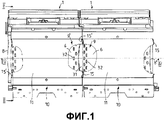
фиг.1: две выполненные в соответствии с изобретением секции желоба с навешенной направляющей струга на виде сверху, частично оборванном;figure 1: two made in accordance with the invention sections of the gutter with a hinged guide plow in a top view, partially ragged;
фиг.2: сечение по линии II-II, указанной на фиг.1;figure 2: section along the line II-II indicated in figure 1;
фиг.3: вид в перспективе стыковой области между двумя соседними секциями желоба, частично оборван;figure 3: a perspective view of the butt region between two adjacent sections of the gutter, partially torn off;
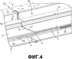
фиг.4: две секции желоба, показанные на фиг.1, на сечении по линии IV-IV, указанной на фиг.1;figure 4: two sections of the gutter shown in figure 1, in section along the line IV-IV, indicated in figure 1;
фиг.5: стыковой зазор между двумя расположенными рядом донными частями ванны по первому примеру осуществления;5: butt gap between two adjacent bottom parts of the bath according to the first embodiment;
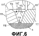
фиг.6: стыковой зазор между двумя расположенными рядом донными частями ванны по второму примеру осуществления; и6: butt gap between two adjacent bottom parts of the bath according to the second embodiment; and
фиг.7: стыковой зазор между новой и восстановленной ваннами верхней ветви.7: butt gap between the new and restored baths of the upper branch.
На фиг.1-4 позицией 1 обозначена предлагаемая изобретением секция желоба. Цепной скребковый конвейер, который, например, прокладывается в подземном добычном забое установки для добычи угля, состоит чаще всего из множества, например, более 200 секций 1 желоба идентичной конструкции, на концах которых затем располагаются также приводные желоба, чтобы передвигать циркулирующую скребковую ленту, снабженную присоединенным скребком (не изображен), в верхней ветви 2 отдельных секций 1 желоба в одном направлении, а в нижней ветви 3 возвращать обратно. Секция 1 желоба состоит, как, в частности, хорошо видно на фиг.2, в показанном примере осуществления из первой, здесь одновременно содержащей встроенную направляющую струга, боковой щеки 4, которая представляет собой сложную литую деталь, и значительно уменьшенной по сравнению с ней второй, при эксплуатации располагаемой со стороны закладки боковой щеки 5, причем две эти боковые щеки 4, 5 по существу жестко соединены друг с другом с одной стороны промежуточным дном 6, а с другой стороны дном нижней ветви 7. Показанный пример осуществления двух боковых щек 4, 5 и позиционирования и расположения промежуточного дна 6 и дна 7 нижней ветви является только примером секции желоба, и отдельные части могли бы в принципе иметь другую конструкцию, или как, например, дно 7 нижней ветви, может также отсутствовать, в зависимости от конструкции и цели применения секции желоба.1-4, 1 denotes the gutter section according to the invention. The chain scraper conveyor, which, for example, is laid in the underground mining face of a coal mining plant, most often consists of many, for example, more than 200
На соединяющее боковые щеки 4, 5 промежуточное дно 6 опирается ванна 10 верхней ветви, которая известным образом состоит из ровного дна 11 ванны, а также двух боковых профилей 12, которые на обращенных друг к другу сторонах имеют контур 13 профиля, по которому могут направляться своими концами не показанные скребки. У каждой ванны 10 (сменный лоток) верхней ветви имеются две боковые кромки (14, фиг.2), которые проходят по существу параллельно боковым профилям 12, а также две находящиеся друг напротив друга торцевые кромки 15, 15', которые, как, в частности, показано на виде сверху на фиг.1, имеют волнообразную ограничительную линию, причем эти торцевые кромки 15, 15' выполнены ответными друг другу, чтобы в смонтированном состоянии выпуклость, например, на торцевой кромке 15 вставлялась в углубление на торцевой кромке 15', и наоборот. Между каждыми двумя донными частями 11 ванн 10 верхней ветви соседних секций 1 желоба образуется стыковая область или стыковой зазор 50, через который благодаря волнообразному характеру торцевых кромок 15, 15' могут переходить скребки скребковой цепи, не ударяясь в стыковой области о торцевые кромки. Для достаточного перекрытия стыкового зазора у каждой секции 1 желоба концевая кромка 8 промежуточного дна 6 выступает на одной стороне дальше вперед, чем расположенная над ней торцевая кромка 15' дна 11 ванны, в то время как на противоположном конце секции 1 желоба соответствующая концевая кромка 8' расположена со смещением внутрь (смещением назад), что особенно хорошо видно на фиг.4. Чтобы обеспечить угловую подвижность, концевые кромки 8, 8' промежуточного дна также имеют волнообразную ограничительную линию, при этом волнистый контур может быть аналогичным или идентичным волнистому контуру торцевых кромок 15, 15' донных частей 11 ванны и предпочтительно имеет центральную выпуклую зону и многократно согнутые под углом зоны по краям, как хорошо видно на фиг.1 и 3.On the connecting
В соответствии с изобретением обе торцевые кромки 15, 15' донных частей 11 ванны дополнительно к фаске 16 на переходе верхней стороны 11' в торцевую кромку 15 снабжены скосом 17, который, как детально изображено на фиг.5, в соответствии с одним из особенно предпочтительных вариантов осуществления вновь изготавливаемых ванн 10 верхней ветви проходит непрерывно в виде наклонной поверхности до нижней стороны 18 донной части 11 ванны. Во всем стыковом зазоре 50 между двумя донными частями 11 ванн образуется, таким образом, открывающийся вверх V-образный зазор, который одновременно распространяется вниз до промежуточного дна 6 секции желоба, то есть до зоны перекрытия. Фаска 16 здесь имеет угол, который относительно верхней стороны 11' донной части 11 ванны проходит под углом 45°, и в общем случае может составлять примерно от 25° до 50°. Относительно общей толщины донной части 11 ванны, равной здесь 40 мм, фаска 16 распространяется на глубину, равную здесь 5 мм. К фаске 16 примыкает непосредственно скос 17 под углом, который больше, в частности, значительно больше, чем угол фаски, и придает скосу 17 гораздо более крутой характер, чем у фаски 16. В одном из особенно предпочтительных вариантов осуществления угол наклона скоса 17 составляет около 70° относительно верхней стороны 11' и распространяется, не изменяясь, до нижней стороны 18.In accordance with the invention, both
На фиг.6 показан один из альтернативных примеров осуществления, при котором донные части 111 ванны снабжены фаской 116, имеющей те же размеры, что и в предыдущем примере осуществления, а также фаской 117, которая проходит не до нижней стороны 118 донных частей 111 ванны, а заканчивается на расстоянии, равном здесь примерно 2 мм от нижней стороны 118, так как между нижней стороной 118 и скосом 117 находится еще участок 119 прямой кромки, на котором торцевые кромки 115' или, соответственно, 115 проходят перпендикулярно верхней стороне 111' или, соответственно, нижней стороне 118 донных частей 111 ванны. Такая конфигурация предлагается, в частности, когда ванны верхней ветви ремонтируются после предшествовавшего использования.Figure 6 shows one alternative embodiment in which the
На фиг.7 показан стыковой зазор 150 желоба между донной частью 111 ванны, показанной на фиг.6, и донной частью 11 ванны, показанной на фиг.5. Один скос 17 проходит при этом прямолинейно до нижней стороны 18, в то время как другой скос 117 сначала переходит в участок 119 прямой кромки.7 shows the
Из фиг.1 и 3 видно также, что промежуточное дно 6 соответственно вблизи концевых кромок выполнено с рядами 9 или, соответственно, 9' здесь продолговатых и распространяющихся поперек направления движения скребков овальных удлиненных отверстий 32. Плотность удлиненных отверстий 32 в ряду 9 на той концевой кромке 8 промежуточного дна 6, которая в смонтированном состоянии перекрывается расположенной над ней донной частью 11 ванны, выше, чем плотность в ряду 9', который находится на расположенной со смещением назад концевой кромке 8' промежуточного дна 6. Между рядом 9, содержащим большее количество удлиненных отверстий 32, и соответствующей концевой кромкой 8 выполнено уплощение 31, как особенно отчетливо показано на фиг.3, которое несколько сужает промежуточное дно 6 в направлении концевой кромки 8, чтобы улучшить угловую подвижность по вертикали. Так как из-за уплощения 31 риск скопления мелкого угля в промежуточном зазоре увеличивается, большее количество удлиненных отверстий 32 в ряду 9, которые, в принципе, проходят параллельно концевой кромке 8, служит одновременно в качестве барьера для мелкого угля, который не может пройти вниз за промежуточный зазор. Кроме того, на фиг.3 хорошо видно, что на нижней стороне донных частей 11 отдельных ванн соответственно приварены куски 20 листового металла, которые в смонтированном состоянии вставляются в смотровые отверстия 30 в соответствующем промежуточном дне 6 с геометрическим замыканием, чтобы закрепить донные части 11 ванн и вместе с тем весь сменный лоток 10 на нижней конструкции, образованной посредством боковых щек 4, 5 и промежуточного дна 6, в направлении движения скребков.From Figs. 1 and 3 it is also seen that the
Для специалиста из предыдущего описания вытекают многочисленные модификации, которые должны попасть в область защиты прилагаемых пунктов формулы изобретения. В примерах осуществления показана фаска с углом, равным 45°, при глубине, равной 5 мм. В зависимости от толщины листового металла как глубина фаски, так и угол фаски может варьироваться в определенных пределах. То же самое относится также к углу наклонной поверхности, который предпочтительно составляет примерно 70°. Вместо прямолинейного характера скоса мог бы быть также предусмотрен выпуклый или соответственно многократно согнутый под углом характер скоса, при этом предпочтительно крутизна скоса соответственно увеличивается в направлении нижней стороны. Боковые щеки могут быть выполнены из литых деталей, плит, сварной конструкции и т.п., а также с направляющей для добычных машин или без нее.For the specialist from the previous description, numerous modifications follow that should fall within the scope of protection of the attached claims. In the embodiments, a chamfer is shown with an angle of 45 ° at a depth of 5 mm. Depending on the thickness of the sheet metal, both the depth of the chamfer and the angle of the chamfer can vary within certain limits. The same applies to the angle of the inclined surface, which is preferably approximately 70 °. Instead of the straight-line character of the bevel, a bevel character that is convex or correspondingly repeatedly angled at an angle could also be provided, preferably the slope of the bevel accordingly increases in the direction of the lower side. Side cheeks can be made of cast parts, plates, welded structures, etc., as well as with or without a guide for mining machines.
Claims (12)
Applications Claiming Priority (3)
| Application Number | Priority Date | Filing Date | Title |
|---|---|---|---|
| DE202009004911.6 | 2009-06-10 | ||
| DE202009004911U DE202009004911U1 (en) | 2009-06-10 | 2009-06-10 | Obertrumwanne for a trough shot and channel shot hereby |
| PCT/IB2010/052521 WO2010143123A1 (en) | 2009-06-10 | 2010-06-07 | Upper-strand well for a trough pan and trough pan having such an upper-strand well |
Publications (2)
| Publication Number | Publication Date |
|---|---|
| RU2011154041A RU2011154041A (en) | 2013-07-20 |
| RU2521905C2 true RU2521905C2 (en) | 2014-07-10 |
Family
ID=41011569
Family Applications (1)
| Application Number | Title | Priority Date | Filing Date |
|---|---|---|---|
| RU2011154041/11A RU2521905C2 (en) | 2009-06-10 | 2010-06-07 | Upper reach bath for gutter section and gutter section fitted by such bath |
Country Status (7)
| Country | Link |
|---|---|
| US (1) | US8783445B2 (en) |
| EP (1) | EP2440480B1 (en) |
| CN (1) | CN102459036B (en) |
| DE (1) | DE202009004911U1 (en) |
| PL (1) | PL2440480T3 (en) |
| RU (1) | RU2521905C2 (en) |
| WO (1) | WO2010143123A1 (en) |
Cited By (2)
| Publication number | Priority date | Publication date | Assignee | Title |
|---|---|---|---|---|
| RU177077U1 (en) * | 2016-09-09 | 2018-02-07 | Общество С Ограниченной Ответственностью "Корум Групп" | SECTION INSPECTION TROUBLE SCRAPER CONVEYOR |
| RU195459U1 (en) * | 2018-05-29 | 2020-01-29 | Ооо "Корум Груп" | SCRAPER CONVEYOR CHANNEL SECTION |
Families Citing this family (3)
| Publication number | Priority date | Publication date | Assignee | Title |
|---|---|---|---|---|
| DE202010013068U1 (en) * | 2010-12-06 | 2012-03-07 | Bucyrus Europe Gmbh | Connecting device for a trough shot of mining equipment, channel shot and attachment thereto |
| CN107824901B (en) * | 2017-12-14 | 2020-02-11 | 广东长盈精密技术有限公司 | Machining method of highlight chamfer |
| EP3581525B1 (en) * | 2018-06-14 | 2021-08-18 | Caterpillar Global Mining Europe GmbH | Conveyor pan |
Citations (5)
| Publication number | Priority date | Publication date | Assignee | Title |
|---|---|---|---|---|
| DE3405986A1 (en) * | 1984-02-20 | 1985-08-22 | Gewerkschaft Eisenhütte Westfalia, 4670 Lünen | GUTTER FOR CHAIN SCRATCH CONVEYOR |
| DE3903347A1 (en) * | 1989-02-04 | 1990-08-09 | Gewerk Eisenhuette Westfalia | Conveying trough for scraper chain conveyors |
| US6267449B1 (en) * | 1998-09-25 | 2001-07-31 | Dbt Deutche Bergbau-Technik Gmbh | Guide arrangement for a drum-type mineral cutting machine |
| RU2286300C2 (en) * | 2002-05-17 | 2006-10-27 | Дбт Гмбх | Conveyor trough section |
| RU2309106C2 (en) * | 2002-08-08 | 2007-10-27 | Дбт Гмбх | Conveyor trough section |
Family Cites Families (17)
| Publication number | Priority date | Publication date | Assignee | Title |
|---|---|---|---|---|
| DE2352289C2 (en) * | 1973-10-18 | 1975-07-03 | Kloeckner-Werke Ag, 4100 Duisburg | Face conveyors, in particular single or multiple chain scraper conveyors |
| FR2249821B1 (en) * | 1973-11-06 | 1979-07-20 | Halbach & Braun | |
| DE2836132A1 (en) * | 1978-08-18 | 1980-02-28 | Gewerk Eisenhuette Westfalia | CHAIN SCRAPER CONVEYOR WITH PLANE GUIDE FOR UNDERGROUND LEVELING COMPANIES |
| DE2915584A1 (en) * | 1979-04-18 | 1980-10-30 | Gewerk Eisenhuette Westfalia | CHAIN SCRAP CONVEYOR, ESPECIALLY FOR MINING UNDERGROUND COMPANIES |
| DE3335057A1 (en) * | 1983-09-28 | 1985-04-04 | Gewerkschaft Eisenhütte Westfalia, 4670 Lünen | GUTTER SHOT FOR CHAIN SCRATCH CONVEYOR |
| DE3431351C2 (en) | 1984-08-25 | 1986-07-17 | Halbach & Braun Industrieanlagen, 5600 Wuppertal | Trough section for a conveyor trough |
| DE3613551A1 (en) * | 1985-07-26 | 1987-02-05 | Gewerk Eisenhuette Westfalia | GUTTER SHOT FOR CHAIN SCRATCH CONVEYOR WITH INTERCHANGEABLE CONVEYOR |
| DE3909947A1 (en) | 1989-03-25 | 1990-09-27 | Telefunken Electronic Gmbh | AM detector circuit having a coupling coil |
| DE4006183C2 (en) * | 1990-03-01 | 1998-07-09 | Dbt Gmbh | Channel shot for chain scraper conveyors, especially for medium and double medium chain scraper conveyors |
| DE9313677U1 (en) | 1993-09-10 | 1993-11-18 | Westfalia Becorit Ind Tech | Channel shot for chain scraper conveyors, especially for mining applications |
| US5871261A (en) * | 1997-04-28 | 1999-02-16 | Longwall-Associates, Inc. | Longwall mine face conveyor pan and method of fabricating |
| US6401912B1 (en) * | 1999-10-26 | 2002-06-11 | Clarence L. Bandy, Jr. | Conveyor pan assembly with replaceable deck |
| DE10050701B4 (en) | 2000-10-13 | 2005-02-10 | Dbt Gmbh | Drive and tensioning station of a chain scraper conveyor for mining operations |
| DE10222599C1 (en) * | 2002-05-17 | 2003-10-09 | Dbt Gmbh | Channel for an underground chain or hauling conveyor comprises a lower trunk and an upper trunk for guiding the bucket of a drag chain, a welded frame construction, a conveyor base, and channel-connecting devices |
| DE10222597A1 (en) * | 2002-05-17 | 2003-11-27 | Dbt Gmbh | conveyor pan |
| DE202005004383U1 (en) | 2005-03-16 | 2005-05-25 | Dbt Gmbh | Planing guide shot for Gleithobel |
| DE202008011518U1 (en) * | 2008-08-29 | 2009-10-08 | Bucyrus Dbt Europe Gmbh | Trough shot with change trough and change trough |
-
2009
- 2009-06-10 DE DE202009004911U patent/DE202009004911U1/en not_active Expired - Lifetime
-
2010
- 2010-06-07 EP EP10735089.4A patent/EP2440480B1/en active Active
- 2010-06-07 CN CN201080025512.3A patent/CN102459036B/en active Active
- 2010-06-07 RU RU2011154041/11A patent/RU2521905C2/en not_active IP Right Cessation
- 2010-06-07 PL PL10735089T patent/PL2440480T3/en unknown
- 2010-06-07 WO PCT/IB2010/052521 patent/WO2010143123A1/en active Application Filing
- 2010-06-07 US US13/377,222 patent/US8783445B2/en active Active
Patent Citations (5)
| Publication number | Priority date | Publication date | Assignee | Title |
|---|---|---|---|---|
| DE3405986A1 (en) * | 1984-02-20 | 1985-08-22 | Gewerkschaft Eisenhütte Westfalia, 4670 Lünen | GUTTER FOR CHAIN SCRATCH CONVEYOR |
| DE3903347A1 (en) * | 1989-02-04 | 1990-08-09 | Gewerk Eisenhuette Westfalia | Conveying trough for scraper chain conveyors |
| US6267449B1 (en) * | 1998-09-25 | 2001-07-31 | Dbt Deutche Bergbau-Technik Gmbh | Guide arrangement for a drum-type mineral cutting machine |
| RU2286300C2 (en) * | 2002-05-17 | 2006-10-27 | Дбт Гмбх | Conveyor trough section |
| RU2309106C2 (en) * | 2002-08-08 | 2007-10-27 | Дбт Гмбх | Conveyor trough section |
Cited By (2)
| Publication number | Priority date | Publication date | Assignee | Title |
|---|---|---|---|---|
| RU177077U1 (en) * | 2016-09-09 | 2018-02-07 | Общество С Ограниченной Ответственностью "Корум Групп" | SECTION INSPECTION TROUBLE SCRAPER CONVEYOR |
| RU195459U1 (en) * | 2018-05-29 | 2020-01-29 | Ооо "Корум Груп" | SCRAPER CONVEYOR CHANNEL SECTION |
Also Published As
| Publication number | Publication date |
|---|---|
| DE202009004911U1 (en) | 2009-08-27 |
| RU2011154041A (en) | 2013-07-20 |
| WO2010143123A1 (en) | 2010-12-16 |
| CN102459036B (en) | 2015-04-15 |
| EP2440480B1 (en) | 2013-10-02 |
| CN102459036A (en) | 2012-05-16 |
| US8783445B2 (en) | 2014-07-22 |
| EP2440480A1 (en) | 2012-04-18 |
| PL2440480T3 (en) | 2014-03-31 |
| US20120080289A1 (en) | 2012-04-05 |
Similar Documents
| Publication | Publication Date | Title |
|---|---|---|
| RU2521905C2 (en) | Upper reach bath for gutter section and gutter section fitted by such bath | |
| RU2286455C2 (en) | Mining machine with removable guiding member and guiding member | |
| RU2471994C2 (en) | Conveyor pan with edge of improved shape | |
| RU2613659C2 (en) | Linear pan and longwall cutter | |
| RU58175U1 (en) | CHAIN GUIDE FOR DRIVING CHAINS OF UNDERGROUND MINING MACHINES | |
| US7617621B1 (en) | Trenching chain tooth and method for cutting into a body of ice using same | |
| RU2286300C2 (en) | Conveyor trough section | |
| US7392896B2 (en) | Trough pan for a face conveyor with a loading ramp | |
| JPH093802A (en) | Scraping-put and transferring chain for transferring ballastfor road bed for rail | |
| SK278862B6 (en) | Bucket-like member for a bucket conveyer, mainly for use in mining | |
| CN103374874A (en) | Runner segment for an edge protector of a street milling machine and edge protector for a street milling machine | |
| US2275104A (en) | Grating structure | |
| US2594990A (en) | Cribber chain | |
| US20120198950A1 (en) | Feed system for an underground winning machine, rack bar and drive sprocket therefor | |
| RU195459U1 (en) | SCRAPER CONVEYOR CHANNEL SECTION | |
| RU2599151C2 (en) | Face scraper conveyor | |
| GB2333306A (en) | Improved driving and guide arrangement for a scraper chain conveyor | |
| RU2334104C2 (en) | Toolhead for drawknife cutter | |
| US20110000045A1 (en) | Scraper blade and scraper for scraping off materials from a substrate | |
| RU2574090C1 (en) | Face scraper-type cutting conveyor | |
| RU2264496C1 (en) | Excavation chain | |
| JP2000142941A (en) | Guide device for flight | |
| RU2556601C2 (en) | Plough for ploughing plants and ploughing plant for inclined stratum | |
| AU2020403919A1 (en) | Wear part, bucket and method | |
| CN103291296B (en) | Armored surface conveyor |
Legal Events
| Date | Code | Title | Description |
|---|---|---|---|
| MM4A | The patent is invalid due to non-payment of fees |
Effective date: 20170608 |