RU2520148C2 - Control system for agricultural vehicle, agricultural vehicle and method of control of controlled means of product transportation - Google Patents
Control system for agricultural vehicle, agricultural vehicle and method of control of controlled means of product transportation Download PDFInfo
- Publication number
- RU2520148C2 RU2520148C2 RU2010135813/13A RU2010135813A RU2520148C2 RU 2520148 C2 RU2520148 C2 RU 2520148C2 RU 2010135813/13 A RU2010135813/13 A RU 2010135813/13A RU 2010135813 A RU2010135813 A RU 2010135813A RU 2520148 C2 RU2520148 C2 RU 2520148C2
- Authority
- RU
- Russia
- Prior art keywords
- target area
- location
- characteristic points
- frame
- reference frame
- Prior art date
Links
Images

Classifications
-
- A—HUMAN NECESSITIES
- A01—AGRICULTURE; FORESTRY; ANIMAL HUSBANDRY; HUNTING; TRAPPING; FISHING
- A01D—HARVESTING; MOWING
- A01D43/00—Mowers combined with apparatus performing additional operations while mowing
- A01D43/08—Mowers combined with apparatus performing additional operations while mowing with means for cutting up the mown crop, e.g. forage harvesters
- A01D43/086—Mowers combined with apparatus performing additional operations while mowing with means for cutting up the mown crop, e.g. forage harvesters and means for collecting, gathering or loading mown material
- A01D43/087—Mowers combined with apparatus performing additional operations while mowing with means for cutting up the mown crop, e.g. forage harvesters and means for collecting, gathering or loading mown material with controllable discharge spout
-
- B—PERFORMING OPERATIONS; TRANSPORTING
- B65—CONVEYING; PACKING; STORING; HANDLING THIN OR FILAMENTARY MATERIAL
- B65G—TRANSPORT OR STORAGE DEVICES, e.g. CONVEYORS FOR LOADING OR TIPPING, SHOP CONVEYOR SYSTEMS OR PNEUMATIC TUBE CONVEYORS
- B65G67/00—Loading or unloading vehicles
- B65G67/02—Loading or unloading land vehicles
- B65G67/04—Loading land vehicles
-
- B—PERFORMING OPERATIONS; TRANSPORTING
- B65—CONVEYING; PACKING; STORING; HANDLING THIN OR FILAMENTARY MATERIAL
- B65G—TRANSPORT OR STORAGE DEVICES, e.g. CONVEYORS FOR LOADING OR TIPPING, SHOP CONVEYOR SYSTEMS OR PNEUMATIC TUBE CONVEYORS
- B65G67/00—Loading or unloading vehicles
- B65G67/02—Loading or unloading land vehicles
- B65G67/24—Unloading land vehicles
- B65G67/32—Unloading land vehicles using fixed tipping installations
-
- B—PERFORMING OPERATIONS; TRANSPORTING
- B65—CONVEYING; PACKING; STORING; HANDLING THIN OR FILAMENTARY MATERIAL
- B65G—TRANSPORT OR STORAGE DEVICES, e.g. CONVEYORS FOR LOADING OR TIPPING, SHOP CONVEYOR SYSTEMS OR PNEUMATIC TUBE CONVEYORS
- B65G2203/00—Indexing code relating to control or detection of the articles or the load carriers during conveying
- B65G2203/04—Detection means
- B65G2203/041—Camera
Abstract
Description
Область техники, к которой относится изобретениеFIELD OF THE INVENTION
Настоящее изобретение относится к системе управления для сельскохозяйственного транспортного средства, осуществляющей управление управляемым средством транспортировки продукта сельскохозяйственного транспортного средства, в частности выгрузным желобом кормоуборочного комбайна, для подачи продукции к целевой области, при этом указанная система управления содержит устройство формирования трехмерных изображений для получения кадров, отображающих, по меньшей мере, часть целевой области, процессор данных и устройство памяти, причем указанная система управления извлекает из этих кадров информацию для управления средством транспортировки продукта.The present invention relates to a control system for an agricultural vehicle, controlling a controlled means of transporting a product of an agricultural vehicle, in particular a discharge chute of a forage harvester, for supplying products to a target area, said control system comprising a three-dimensional image forming device for receiving frames displaying at least a portion of the target area, a data processor and a memory device, wherein the specified control system extracts information from these frames for controlling the product transportation means.
Кроме того, изобретение относится к сельскохозяйственному транспортному средству, содержащему систему управления, и способу управления управляемым средством транспортировки продукта сельскохозяйственного транспортного средства с помощью системы управления.In addition, the invention relates to an agricultural vehicle comprising a control system and a method for controlling a controlled means of transporting a product of an agricultural vehicle using a control system.
Уровень техникиState of the art
В патентном документе DE 4426059 A1 описан комбайн со спускным или выгрузным желобом для выгрузки собранного материала в контейнер для перевозки продукции транспортной тележки. С нижней стороны желоба на некотором расстоянии от выгрузного конца присоединена камера. Камера формирует изображение конца желоба и открытого верха контейнера для перевозки продукции, причем указанное изображение передается на монитор в кабину водителя. Кроме того, предлагается использовать обработку изображения для управления желобом, чтобы удерживать его направленным на открытый верх контейнера для перевозки продукции, автоматически обеспечивая постоянное попадание выгружаемого продукта в цель, т.е. через открытый верх контейнера для перевозки продукции.DE 4426059 A1 describes a harvester with a discharge or discharge chute for unloading collected material into a container for transporting products of a transport trolley. A chamber is attached to the lower side of the chute at some distance from the discharge end. The camera forms an image of the end of the gutter and the open top of the container for transporting products, and this image is transmitted to the monitor in the driver's cab. In addition, it is proposed to use image processing to control the gutter to keep it directed to the open top of the product transport container, automatically ensuring that the unloaded product constantly hits the target, i.e. through the open top of the container for transporting products.
В патентном документе EP 1344445 A1 описан комбайн со спускным или выгрузным желобом с насадкой для направления материала, выгружаемого из желоба. К насадке присоединяется камера и, таким образом, направление обзора камеры параллельно направлению выгрузки из желоба. Предлагается использовать две камеры и сшивать формируемые ими изображения, тем самым обеспечивая большее поле обзора. В альтернативном варианте можно одновременно использовать только одну камеру, а именно камеру, формирующую лучшее изображение.Patent Document EP 1344445 A1 describes a harvester with a discharge or discharge chute with a nozzle for guiding material discharged from the chute. A camera is attached to the nozzle and, thus, the direction of view of the camera is parallel to the direction of discharge from the trough. It is proposed to use two cameras and stitch the images formed by them, thereby providing a larger field of view. Alternatively, only one camera can be used at a time, namely a camera that forms the best image.
В патентном документе ЕР 2020174 A1 предлагается использовать стереоскопическую камеру, присоединенную к желобу комбайна с целью получения трехмерных или 3D изображений контейнера для транспортировки или хранения, в который из желоба высыпается собранный продукт, загружающий при этом контейнер, что обеспечивает возможность управления желобом и перегрузкой продукта. С помощью этих изображений предлагается получать так называемые шаблоны контейнера для хранения, окружающих его зон и уровень заполнения продукцией контейнера для хранения соответственно. Эти шаблоны можно структурировать в виде 3D шаблонов, шаблонов формы, шаблонов текстуры и (или) шаблонов цвета. Кроме того, предлагается исходя из смещения этих шаблонов от одного изображения к другому получать данные о скорости перемещения и повороте комбайна, скорости перемещения и повороте контейнера для хранения, а также изменения условий загрузки и положения желоба в пространстве соответственно.In patent document EP 2020174 A1, it is proposed to use a stereoscopic camera attached to the trough of the combine for the purpose of obtaining three-dimensional or 3D images of a container for transportation or storage, into which a collected product is poured out of the trough, loading the container, which makes it possible to control the trough and overload the product. Using these images, it is proposed to obtain the so-called templates of the storage container, its surrounding zones and the level of filling of the storage container with products, respectively. These patterns can be structured as 3D patterns, shape patterns, texture patterns, and / or color patterns. In addition, it is proposed based on the displacement of these templates from one image to another to receive data on the movement speed and rotation of the combine, the movement speed and rotation of the storage container, as well as changes in loading conditions and the position of the gutter in space, respectively.
При подаче продукта к целевой области с помощью средства транспортировки продукта, например выгрузного желоба, и контроля подачи с помощью устройства формирования трехмерных изображений, например стереоскопической камеры, могут возникнуть проблемы, связанные с пылью и частицами продукта, например листьями и частями листьев, рассеянными в воздухе вокруг средства транспортировки продукта и в зоне между средством транспортировки продукта и целевой областью, и создающими шумы на изображениях, создаваемых устройством формирования трехмерных изображений. Это, в свою очередь, затрудняет надлежащее управление средством транспортировки продукта на основе изображений. Таким образом, системам управления, относящимся к известному уровню техники, трудно отличать целевую область и продукт, высыпаемый в целевую область, от шума, такого как пыль и частицы, рассеянные в воздухе между средством транспортировки продукта и целевой областью.When delivering a product to a target area using a product transportation means, such as a discharge chute, and controlling the feed using a three-dimensional imaging device, such as a stereoscopic camera, problems may arise with dust and particles of the product, such as leaves and parts of leaves scattered in the air around the product transportation means and in the area between the product transportation means and the target area, and creating noise in the images created by the three-dimensional device n images. This, in turn, makes it difficult to properly manage the image-based product transportation tool. Thus, it is difficult for control systems of the prior art to distinguish between the target region and the product poured into the target region from noise such as dust and particles scattered in the air between the product transport means and the target region.
Раскрытие изобретенияDisclosure of invention
Задачей настоящего изобретения является преодоление или сведение к минимуму этой проблемы.An object of the present invention is to overcome or minimize this problem.
Это достигается с помощью системы управления для сельскохозяйственного транспортного средства, осуществляющей управление управляемым средством транспортировки продукта сельскохозяйственного транспортного средства, в частности выгрузным желобом кормоуборочного комбайна, для подачи продукции к целевой области, при этом указанная система управления содержит устройство формирования трехмерных изображений для получения кадров, отображающих, по меньшей мере, часть целевой области, процессор данных и устройство памяти, причем указанная система управления выполнена с возможностью извлечения информации из указанных кадров для управления средством транспортировки продукта, а именно с возможностью получения эталонного кадра, который содержит трехмерную информацию о расположении, по меньшей мере, части целевой области, идентификации ряда характеристических точек или отличительных признаков в эталонном кадре, получения от устройства формирования трехмерных изображений нового кадра, отображающего, по меньшей мере, часть целевой области, анализа нового кадра для идентификации ряда характеристических точек в новом кадре, поиска и сопоставления характеристических точек в эталонном кадре и новом кадре, анализа пары согласованных характеристических точек для определения группы пар, демонстрирующих общее изменение расположения от эталонного кадра к новому кадру, и формирования сигнала с учетом результатов последнего анализа. При помощи идентификации группы пар характеристических точек, демонстрирующих общее изменение расположения, идентифицируется группа точек изображения, принадлежащих поверхности общего твердого тела. Этим твердым телом будут являться целевая область и продукт, высыпаемый в целевую область.This is achieved by using a control system for an agricultural vehicle that controls a controlled means of transporting a product of an agricultural vehicle, in particular a feed chute of a forage harvester, for supplying products to a target area, said control system comprising a three-dimensional image forming device for receiving frames displaying at least a portion of the target area, a data processor and a memory device, wherein I control system is configured to extract information from these frames to control the product transportation means, namely with the possibility of obtaining a reference frame that contains three-dimensional information about the location of at least part of the target area, identifying a number of characteristic points or distinguishing features in the reference frame receiving from the 3D image forming apparatus a new frame displaying at least a portion of the target area, analyzing the new frame for identically fication of a number of characteristic points in a new frame, search and comparison of characteristic points in a reference frame and a new frame, analysis of a pair of matched characteristic points to determine a group of pairs showing a general change in location from the reference frame to a new frame, and signal generation taking into account the results of the last analysis. By identifying a group of pairs of characteristic points demonstrating a general change in location, a group of image points belonging to the surface of a common solid is identified. This solid will be the target area and the product poured into the target area.
Для целей настоящего изобретения «расположение» означает позицию и ориентацию. Таким образом, расположение представляет собой сочетание изменения позиции, вызванного поступательным движением, и изменения ориентации, вызванного вращением вокруг оси. Таким образом, точки, демонстрирующие общее изменение расположения, представляют собой точки, которые переместились со своей позиции в эталонном кадре к своей позиции в новом кадре за счет общего поступательного движения и общего вращения вокруг общей оси.For the purposes of the present invention, “location” means position and orientation. Thus, an arrangement is a combination of a change in position caused by translational motion and a change in orientation caused by rotation around an axis. Thus, points demonstrating a general change in location are points that have moved from their position in the reference frame to their position in the new frame due to the common translational motion and general rotation around the common axis.
Таким образом, точки, демонстрирующие наличие пыли и частиц, определенным образом отфильтровываются, тогда как точки, принадлежащие с большой степенью определенности к целевой области, идентифицируются.Thus, points demonstrating the presence of dust and particles are filtered out in a certain way, while points belonging to the target area with a high degree of certainty are identified.
В предпочтительном варианте осуществления система управления обеспечивает указанный сигнал с учетом указанного общего изменения расположения и/или относительных позиций отдельных пар согласованных характеристических точек в группе пар, демонстрирующих общее изменение расположения. Принимая во внимание общее изменение расположения, можно определить текущую позицию цели относительно сельскохозяйственного транспортного средства, при этом указанный сигнал предпочтительно представляет собой управляющий сигнал для управления средством транспортировки продукта, обеспечивая, таким образом, сохранение ориентации средства транспортировки продукта на цель. Принимая во внимание относительные позиции отдельных пар согласованных характеристических точек в группе пар, демонстрирующих общее изменение расположения, можно контролировать степень заполнения различных областей цели, при этом сигнал может быть управляющим сигналом для управления средством транспортировки продукта с целью следования стратегии заполнения.In a preferred embodiment, the control system provides said signal, taking into account said general change in location and / or relative positions of individual pairs of agreed characteristic points in a group of pairs showing a general change in location. Taking into account the general change in location, it is possible to determine the current position of the target relative to the agricultural vehicle, and this signal is preferably a control signal for controlling the product transport means, thereby ensuring that the product transport means is oriented towards the target. Taking into account the relative positions of individual pairs of agreed characteristic points in a group of pairs showing a general change in location, the degree of filling of various areas of the target can be controlled, and the signal can be a control signal for controlling the product transportation means in order to follow the filling strategy.
В предпочтительном варианте осуществления система содержит монитор, при этом указанный сигнал содержит информационный сигнал, отображаемый на мониторе. Принимая во внимание относительные позиции отдельных пар согласованных характеристических точек в группе пар, демонстрирующих общее изменение расположения, в этом варианте осуществления можно четко отобразить на мониторе степень заполнения различных областей цели, например, чтобы водитель транспортного средства мог отслеживать заполнение цели или осуществлять управляющие действия, следуя стратегии заполнения.In a preferred embodiment, the system comprises a monitor, wherein said signal comprises an information signal displayed on the monitor. Taking into account the relative positions of individual pairs of agreed characteristic points in a group of pairs showing a general change in location, in this embodiment, the degree of filling of different areas of the target can be clearly displayed on the monitor, for example, so that the driver of the vehicle can monitor the filling of the target or carry out control actions by following filling strategies.
Предпочтительно система управления выполнена с возможностью определения расположения целевой области, соответствующего эталонному кадру, и обновления указанного расположения с учетом указанного общего изменения расположения. Это позволяет определять текущее расположение целевой области даже в случае, когда текущее изображение содержит слишком много шума для определения расположения на основе изображения как такового.Preferably, the control system is configured to determine the location of the target area corresponding to the reference frame, and update the specified location, taking into account the specified general change in location. This allows you to determine the current location of the target area, even when the current image contains too much noise to determine the location based on the image as such.
Предпочтительно система управления выполнена с возможностью определения расположения по меньшей мере части целевой области в системе отсчета, предпочтительно связанной с сельскохозяйственным транспортным средством.Preferably, the control system is configured to locate at least a portion of the target area in a reference system, preferably associated with an agricultural vehicle.
Предпочтительно, кроме того, система управления выполнена с возможностью обновления расположения целевой области в указанной системе отсчета. Это позволяет определять расположение целевой области также для частей целевой области, выходящих за пределы изображения текущего кадра.Preferably, in addition, the control system is configured to update the location of the target area in the specified reference system. This allows you to determine the location of the target area also for parts of the target area beyond the image of the current frame.
Предпочтительно система управления выполнена с возможностью определения поверхности целевой области и определения отдельных пар согласованных характеристических точек в группе пар, демонстрирующих общее изменение расположения, которые не расположены на поверхности целевой области, представляющих поверхность продукта, подаваемого в целевую область. Это позволяет определять точки поверхности продукта, высыпаемого в целевую область, с большой достоверностью, что обеспечивает соответствующую большую достоверность при определении количества засыпанного продукта или степень заполнения продуктом целевой области. Следует отметить, что общая поверхность продукта, засыпаемого в целевую область, обычно представляет собой подвижную поверхность, поскольку из средства транспортировки продукта более или менее непрерывно поступает новый материал. Однако поверхность в целом в большинстве случаев изменяется не одновременно, при этом отдельные области время от времени остаются неподвижными. Таким образом, характеристические точки, принадлежащие к отдельным неподвижным в данный момент областям поверхности продукта, засыпаемого в целевую область, можно отыскивать и сопоставлять в двух последовательных изображениях, например, полученным с интервалом 0,2-0,3 секунды.Preferably, the control system is configured to determine the surface of the target area and to determine individual pairs of matched characteristic points in a group of pairs showing a general change in location that are not located on the surface of the target area, representing the surface of the product fed to the target area. This allows you to determine the surface points of the product poured into the target area with great confidence, which provides corresponding greater reliability in determining the amount of product poured or the degree of filling of the target area with the product. It should be noted that the total surface of the product, which is poured into the target area, is usually a moving surface, since new material flows more or less continuously from the product transportation means. However, the surface as a whole in most cases does not change simultaneously, while some areas remain motionless from time to time. Thus, the characteristic points belonging to the individual currently stationary areas of the surface of the product that is poured into the target area can be found and compared in two consecutive images, for example, obtained with an interval of 0.2-0.3 seconds.
Предпочтительно система управления содержит средства для определения расположения, по меньшей мере, части целевой области, которые обеспечивают меру степени надежности определенного расположения, при этом указанная система управления выполнена с возможностью обновления расположения целевой области на основе расположения, определенного средствами определения расположения, когда указанная степень надежности высока. Это позволяет всегда определять расположение с большой достоверностью, поскольку эффекта дрейфа при определении за счет суммирования незначительных изменений расположения от кадра к кадру удается избежать.Preferably, the control system comprises means for determining the location of at least part of the target area, which provide a measure of the degree of reliability of a specific location, while the specified control system is configured to update the location of the target area based on the location determined by the location means when the specified degree of reliability high. This allows you to always determine the location with great confidence, since the drift effect in determining due to the summation of minor changes in the location from frame to frame can be avoided.
В предпочтительном варианте осуществления средства для определения расположения по меньшей мере части целевой области содержат средства для анализа трехмерного кадра. Это позволяет определить расположение по кадру, создаваемому устройством формирования трехмерных изображений, тем самым избегая необходимости в отдельном устройстве для определения расположения.In a preferred embodiment, the means for determining the location of at least a portion of the target area comprise means for analyzing a three-dimensional frame. This allows you to determine the location on the frame created by the device for forming three-dimensional images, thereby avoiding the need for a separate device for determining the location.
Предпочтительно система управления содержит средства для определения позиции и направления обзора устройства формирования трехмерных изображений, при этом система управления выполнена с возможностью игнорирования точек в трехмерных кадрах, показывающих позиции ниже определенного уровня относительно устройства формирования трехмерных изображений. Такой способ позволяет отфильтровать несущественные детали изображения, которые могут вносить шум. Такие несущественные детали могут быть участком земли, окружающим целевую область.Preferably, the control system comprises means for determining a position and a viewing direction of the three-dimensional image forming apparatus, wherein the control system is configured to ignore points in three-dimensional frames showing positions below a certain level with respect to the three-dimensional image forming apparatus. This method allows you to filter out irrelevant image details that may introduce noise. Such non-essential details may be a piece of land surrounding the target area.
В еще одном предпочтительном варианте осуществления система управления выполнена с возможностью определения областей ожидания, в пределах которых выполняется поиск характеристических точек в эталонном кадре и/или новом кадре в целях сопоставления. Это позволяет осуществлять поиск отдельных характеристических точек в пределах ограниченной области изображения, уменьшая время обработки, при этом области изображения, в которых существенные характеристические точки не ожидаются, можно исключить из поиска, избегая тем самым возможного шума.In yet another preferred embodiment, the control system is configured to determine waiting areas within which characteristic points are searched for in a reference frame and / or a new frame for comparison purposes. This allows you to search for individual characteristic points within a limited area of the image, reducing processing time, while areas of the image in which significant characteristic points are not expected can be excluded from the search, thereby avoiding possible noise.
В еще одном варианте осуществления система управления выполнена с возможностью поиска и сопоставления характеристических точек в новом кадре с характеристическими точками в нескольких ранее полученных кадрах. Это позволяет найти в новом кадре большее количество характеристических точек, представляющих поверхность целевой области или засыпанного в нее продукта. Кроме того, сравнивая расположение характеристических точек в новом кадре с расположениями характеристических точек в нескольких кадрах, полученных за более продолжительный промежуток времени, чем промежуток времени или интервал между двумя последовательными кадрами, можно определить изменение расположения с большей определенностью.In yet another embodiment, the control system is configured to search and match characteristic points in a new frame with characteristic points in several previously received frames. This allows you to find in the new frame a larger number of characteristic points representing the surface of the target area or the product filled into it. In addition, by comparing the location of the characteristic points in the new frame with the locations of the characteristic points in several frames obtained over a longer period of time than the period of time or the interval between two consecutive frames, it is possible to determine the location change with more certainty.
Соответственно, задача изобретения решена с помощью сельскохозяйственного транспортного средства по пункту 14 формулы изобретения и способа по пункту 15 формулы изобретения.Accordingly, the object of the invention is solved by an agricultural vehicle according to paragraph 14 of the claims and the method according to paragraph 15 of the claims.
Краткое описание чертежейBrief Description of the Drawings
Ниже изобретение более подробно объясняется с помощью примеров вариантов осуществления со ссылкой на следующие схематические чертежи.Below the invention is explained in more detail using examples of embodiments with reference to the following schematic drawings.
На фиг.1 показан кормоуборочный комбайн и транспортная тележка.1 shows a forage harvester and a transport trolley.
На фиг.2 показано изображение транспортной тележки.Figure 2 shows an image of a transport trolley.
На фиг.3 показано другое изображение транспортной тележки.Figure 3 shows another image of a transport trolley.
На фиг.4 показана блок-схема, иллюстрирующая способ в соответствии с настоящим изобретением.4 is a flowchart illustrating a method in accordance with the present invention.
Осуществление изобретенияThe implementation of the invention
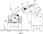
На фиг.1 показан вид спереди кормоуборочного комбайна 1 с жаткой 3, ходовыми колесами 5, кабиной водителя 7 и выгрузной или спускной желоб 9. В процессе работы жатка 3 собирает сельскохозяйственную культуру (продукт), которая обрабатывается комбайном 1 и выгружается из желоба 9. Для сбора выгружаемого продукта транспортная тележка 11 перемещается рядом с бортом кормоуборочного комбайна 1. Из состава транспортной тележки 11 на фиг.1 показаны только ходовые колеса 13 и контейнер для перевозки продукции с днищем 15, боковыми стенками 17, 18 и открытым верхом 19.Figure 1 shows a front view of the
Желоб 9 известным по существу способом монтируется на комбайне 1 с возможностью контролируемого вращения вокруг вертикальной оси 21 с помощью приводных механизмов, обозначенных номером 22. Измеритель присоединен к приводному механизму 22, благодаря чему известно положение желоба 9 по отношению к комбайну 1. Желоб 9 имеет продолговатую форму и наружный конец 23, снабженный регулируемой насадкой 25 для направления потока 27 продукта, выгружаемого из желоба 9.The trough 9 is mounted in a manner known per se in the
Устройство формирования трехмерных изображений в виде стереоскопической камеры 29 монтируется на желобе 9 с нижней стороны и на некотором расстоянии от наружного конца 23. Стереоскопическая камера 29 содержит 2 камеры CCD или видеокамеры с объективами 36а и 36b соответственно, имеющие среднее направление 39 просмотра стереоскопической камеры 29. Две камеры помещаются в общем кожухе 41.The device for forming three-dimensional images in the form of a
Стереоскопическая камера предпочтительно представляет собой широкоугольную камеру с большим углом обзора 3, позволяющим камере «видеть» одновременно открытый верх 19 и ближайшую боковую стенку 17 контейнера для перевозки продукции транспортной тележки 11, как показано на фиг.1.The stereoscopic camera is preferably a wide-angle camera with a wide viewing angle of 3, allowing the camera to "see" at the same time the open top 19 and the
В показанном варианте осуществления, помимо соединения, обеспечивающего вращение желоба 9 вокруг вертикальной оси 21, желоб 9 не содержит каких-либо других соединений между корпусом комбайна 1 и камерой 29. Таким образом, положение стереоскопической камеры 29, в частности ее высота над землей, всегда известны. Предполагается, что желоб в альтернативных вариантах осуществления содержит соединения, позволяющие поднимать и опускать желоб, изменяя его общую геометрию. В таких вариантах осуществления измерители могут прикрепляться к соединениям, позволяя задавать текущую геометрию желоба и, тем самым, высоту положения стереоскопической камеры над землей.In the shown embodiment, in addition to the connection for the rotation of the trough 9 around the vertical axis 21, the trough 9 does not contain any other connections between the housing of the
Наличие стереоскопической камеры 29 обеспечивает получение монохромных (или даже цветных) изображений, а также диспаратных изображений контейнера для перевозки продукции. Монохромные изображения могут, например, передаваться на монитор 44 в кабине водителя, чтобы позволить или помочь водителю отслеживать процесс перегрузки продукции в транспортную тележку 11 известным по существу способом, тогда как диспаратное изображение удовлетворяет требованиям к входной информации для автоматического или полуавтоматического управления.The presence of a
Таким образом, кормоуборочный комбайн 1 содержит устройство 46 управления с процессором данных и устройством памяти. Устройство управления принимает изображения или кадры, т.е. файлы данных, содержащие пиксельную информацию об изображениях, от стереоскопической камеры 29, и обрабатывает изображения.Thus, the
В настоящем варианте осуществления устройство 46 управления использует программное обеспечение, относящееся к известному уровню техники, для обработки стереоизображений, полученных от стереоскопической камеры 29. Таким образом, устройство 46 управления получает стереоскопический кадр, содержащий «левый» и «правый» кадр, обеспечиваемый соответственно двумя объективами 36a и 36b. Следует отметить, что определения «левый» и «правый» используются по отношению к двум кадрам или изображениям, формируемым двумя объективами, в соответствии со стандартом в отношении стереоскопического зрения, несмотря на то, что в настоящем варианте осуществления объективы располагаются один над другим, а не рядом друг с другом. Устройство 46 управления обрабатывает стереоскопический кадр для получения диспаратного изображения, т.е. изображения, содержащего информацию о глубине, или трехмерную информацию. Обычно диспаратное изображение получают, анализируя, например, левый кадр попиксельно, отыскивают для каждого пикселя соответствующий пиксель в правом кадре и рассчитывают расстояние от камеры до точки, изображаемой этими пикселями, методом триангуляции. Информация об этом расстоянии присоединяется к пикселю левого кадра, который, таким образом, содержит трехмерную информацию и формирует диспаратное изображение. Диспаратное изображение обрабатывается устройством 46 управления с помощью программного обеспечения, относящегося к известному уровню техники, для распознавания и определения местоположения транспортной тележки 11, в особенности горизонтального края 51 открытого верха 19.In the present embodiment, the
Для этого требуется довольно хорошее стереоизображение без чрезмерных помех. Такие изображения часто могут быть получены в ходе работы, но их часто также не удается получить, например, из-за посторонних частиц и пыли, плавающих в воздухе вокруг желоба 9 и под ним.This requires a pretty good stereo image without excessive interference. Such images can often be obtained in the course of work, but they also often cannot be obtained, for example, due to foreign particles and dust floating in the air around the channel 9 and under it.
Если устройство 46 управления не может с достаточной степенью надежности распознать и определить местоположение транспортной тележки на основе данного кадра, то ему не удается определить расположение края.If the
После получения стереоскопического кадра или изображения без чрезмерных помех и определения на его основе расположение края 51 открытого верха, можно сохранить или отрегулировать положение желоба 9, чтобы направить поток продукции, выгружаемый желобом, на цель, т.е. открытый верх 19, для заполнения контейнера транспортной тележки 11.After receiving a stereoscopic frame or image without excessive interference and determining on its basis the location of the
Транспортная тележка 11 содержит, как упоминалось выше, две боковые стенки, т.е. ближнюю боковую стенку 17 и дальнюю боковую стенку 18 по отношению к комбайну 1. Кроме того, транспортная тележка 11, или ее контейнер для перевозки продукции, содержит переднюю стенку 20a и заднюю стенку 20b. Соответственно, край 51 содержит ближнюю часть 51a края, дальнюю часть 51b края, переднюю часть 51c края и заднюю часть 51d края 51d.
Определив расположение края 51 на стереоизображении, можно попиксельно анализировать область изображения между ближней частью 51a края и дальней частью 51b края, при этом пиксели, которые на основании информации о диспаратном изображении, считаются представляющими точки, расположенные главным образом вертикально ниже дальней части 51b края, относят к дальней боковой стенке 18.Having determined the location of the
Информация о стереокадре, т.е. диспаратном изображении, сохраняется в памяти устройства 46 управления наряду с информацией о расположении края 51. Расположение края берется относительно комбайна 1. Таким образом, определяется расположение, т.е. позиция и ориентация, края 51 и, вследствие этого, транспортной тележки 11 по отношению к комбайну 1.Stereo frame information, i.e. a disparate image is stored in the memory of the
В связи с тем, что расположение или высота стереоскопической камеры 29 над земной поверхностью известна, можно отфильтровать относящуюся к земле информацию, например, исключив информацию, относящуюся к позициям ниже 50 см над уровнем земли. Исключение информации таким способом уменьшает помехи и сокращает обработку данных.Due to the fact that the location or height of the
После получения и сохранения таким путем информации о кадре, по которой можно определить расположение края 51 или, по меньшей мере, части края, содержащей либо переднюю часть 51 с края, либо заднюю часть 51d края вместе с прилегающими сегментами ближней части 51a края и дальней части 51b края, этот кадр обозначают как «эталонный кадр».After receiving and storing in this way information about the frame by which it is possible to determine the location of the
Как показано на фиг.4, система, получив эталонный кадр на начальном шаге 100, действует следующим образом. На первом шаге 101 идентифицируются характеристические точки в эталонном кадре. На втором шаге 103 получают новый стереокадр от стереоскопической камеры 29, при этом новый стереокадр анализируется с целью поиска и идентификации характеристических точек или отличительных признаков в новом стереокадре.As shown in FIG. 4, the system, having received the reference frame in the
На третьем шаге 105 характеристические точки, найденные в эталонном кадре и новом стереокадре, сопоставляют для выделения группы характеристических точек, демонстрирующих общее изменение расположения от эталонного кадра к новому стереокадру. Общее изменение расположения, найденное таким образом, соответствует изменению расположения транспортной тележки 11 по отношению к стереоскопической камере 29 в течение интервала времени между получением эталонного кадра и нового стереокадра.In a
Если качество нового стереокадра недостаточно для определения расположения края 51 или его части, как объяснялось выше, то на четвертом шаге 107 расположение края 51, зарегистрированное вместе с информацией о новом эталонном кадре, обновляется с учетом общего изменения расположения и принимается в качестве нового расположения, при этом устройство 46 управления может формировать какой-либо сигнал управления, позволяющий продолжать выгрузку потока продукции желобом 9, направленным на цель, т.е. открытый верх 19, или заданное место в пределах открытого верха 19.If the quality of the new stereo frame is not sufficient to determine the location of the
Если качество нового стереокадра достаточно для определения расположения края 51 или его части, новый стереокадр на альтернативном четвертом шаге 109 используется в качестве нового эталонного кадра.If the quality of the new stereo frame is sufficient to determine the location of the
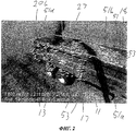
На фиг.2 представлено изображение транспортной тележки 11, на котором характеристические точки, найденные на указанном изображении и последующем новом изображении, показаны линиями 53, проведенными между парами согласованных характеристических точек. Видно, что на окружающем участке земли не найдено каких-либо точек, которые были отфильтрованы, как упомянуто выше. На изображении виден поток 27 продукции, поступающий в контейнер транспортной тележки 11, при этом следует отметить, что в потоке 27 продукции или в месте его падения внутри транспортной тележки 11 не найдено никаких согласованных характеристических точек. Это вызвано тем, что вокруг потока 27 продукции существуют пыльные условия, создающие помехи, и поверхность продукции, засыпаемой в транспортную тележку 11 в области падения потока продукции, выглядит живой или подвижной из-за ее постоянного поступления. Эти условия делают невозможным определение фактической позиции поверхности продукции, засыпанной в транспортной тележке 11, на основе единственного трехмерного изображения, поскольку для конкретной точки или пикселя, обнаруженной на трехмерном изображении, невозможно определить, принадлежит ли эта точка фактически поверхности засыпанной продукции, или движущемуся потоку 27 продукции. Однако рядом с местом падения потока продукции в течение интервала времени между получением двух последовательных кадров поверхность локально будет находиться в неподвижном состоянии, что позволяет идентифицировать и сопоставить характеристические точки поверхности засыпанной продукции. Эти точки надежно идентифицируют текущую поверхность засыпанной продукции, тем самым обеспечивая возможность определения степени заполнения транспортной тележки 11.Figure 2 presents the image of the
Как упоминалось выше, пиксели, расположенные между дальней и ближней частями 51b и 51a края, подвергаются анализу, по результатам которого могут быть отнесены к дальней боковой стенке 18. Идентифицированные и согласованные характеристические точки, расположенные между дальней и ближней частями 51b и 51a края, относят к поверхности засыпанной продукции, если они не отнесены к дальней боковой стенке 19.As mentioned above, pixels located between the distal and
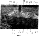
На пятом шаге 111 (фиг.4) сигнал направляется на монитор 44 в качестве информации для водителя или оператора комбайна 1. На фиг.3 представлено полученное на мониторе изображение транспортной тележки 11, на котором край 51 показан с помощью сигналов, поступающих от программного обеспечения, распознающего и определяющего местоположение края. Край отображается в форме кадра 51' изображения, генерируемого устройством 46 управления, и накладывается на изображение, получаемое от камеры, т.е. одного из двух объективов 36a и 36b. Далее степень заполнения постепенно индицируется для различных продольных сечений транспортной тележки 11 с помощью полей 61, 63a, 63b, 65 и 67 изображения, генерируемых устройством 46 управления, и накладывается на изображение, получаемое от камеры. Это индицирование степени заполнения сообщает о том, какие части контейнера транспортной тележки успешно заполнены, а в каких еще остается место для дополнительной погрузки продукции.In the fifth step 111 (Fig. 4), the signal is sent to the monitor 44 as information for the driver or operator of the
Цвета используются для индикации различных степеней заполнения различных областей, например индикация красным цветом означает, что область заполнена (поле 61), индикация областей зеленым цветом - что они еще далеко не заполнены (поле 67), а индикация областей одним или несколькими оттенками желтого цвета - что они близки к заполнению (поле 63a, 63b и 65).Colors are used to indicate different degrees of filling of different areas, for example, a red indication means that the area is filled (field 61), an indication of areas in green means that they are far from filled (field 67), and an indication of areas with one or more shades of yellow means that they are close to filling (
После четвертого и пятого шагов способ возвращается к первому шагу 101, используя информацию об обновленном эталонном кадре.After the fourth and fifth steps, the method returns to the
Идентификация характеристических точек на первом шаге 101 и втором шаге 103 может быть выполнена любым известным способом, например, так называемым способом «обнаружения капли» или так называемым способом «обнаружения углов». Этими способами предусматривается определение чувствительности для пикселя или небольшой группы пикселей, сконцентрированных вокруг какого-либо пикселя. Пиксель, обладающий некоторой чувствительностью, в ближайшем окружении которого обнаруживается другой пиксель с более высокой чувствительностью, отбраковывается, поскольку при слабой чувствительности вероятно возникновение помех.The identification of the characteristic points in the
Сопоставление характеристических точек на третьем шаге 105 может быть выполнено на основе текстурного анализа окрестности соответствующих точек или свойств. Такой анализ выполняется с помощью так называемого «дескриптора свойств», несколько из которых известны специалистам, например нормальная кросс-корреляция с нулевым средним (Zero-mean Normal Cross Correlation), дескриптор SURF (Speeded Up Robust Features, ускоренное отображение устойчивых признаков изображения) и дескриптор SIFT (Scale-Invariant feature transform, масштабно-инвариантная трансформация свойств).The comparison of the characteristic points in the
При сопоставлении характеристической точки, найденной в новом стереокадре, с характеристической точкой в эталонном кадре поиск возможного совпадения можно ограничить областью, где предполагается правильное совпадение. Таким образом, области, которые, как предполагается, относятся не к транспортной тележке 11, а к окружающим ее зонам, например, на внешней стороне передней части края, можно исключить.When comparing the characteristic point found in the new stereo frame with the characteristic point in the reference frame, the search for a possible match can be limited to the area where the correct match is assumed. Thus, areas that are not supposed to belong to the
Определение общего изменения расположенияDetermining a General Change in Location
Взаимное изменение расположения стереоскопической камеры 29 и транспортной тележки 11 за время между одним (эталонным кадром) и другим кадром (новым стереокадром) описывается матрицей преобразования М:The mutual change in the location of the
![]()
![]()
гдеWhere
R - матрица 3×3 (3 строки и 3 столбца), выражающая вращение вокруг трех пространственной осей, иR is a 3 × 3 matrix (3 rows and 3 columns) expressing rotation around three spatial axes, and
T - матрица 3×1, определяющая трансляцию в три пространственных направления;T is a 3 × 1 matrix defining translation in three spatial directions;
M - представляет собой, следовательно, матрицу 4×4.M - is, therefore, a 4 × 4 matrix.
Если Pa обозначает эталонный кадр, относящийся к моменту времени a, а Pb обозначает новый стереокадр, относящийся к более позднему моменту времени b, т.е. a<b, тоIf P a denotes a reference frame at time a, and P b denotes a new stereo frame at a later point in time b, i.e. a <b then
Pb=Mab∗Pa, где Mab представляет собой матрицу, выражающую преобразование из a в b. P b = M ab * P a , where M ab is a matrix expressing the transformation from a to b.
Обращаясь к упомянутому выше третьему шагу 105, получаем, что M представляет собой вариант осуществления настоящего изобретения, полученный по методу ПСД (произвольно-селективного доступа):Turning to the above
Если fas - характеристическая точка №s в Pa, которая была сопоставлена с fbs, представляющей собой характеристическую точку №s в Pb, и, соответственно, fat - характеристическая точка №t в Pa, которая была сопоставлена с fbt, представляющей собой характеристическую точку №t в Pb, a fau - характеристическая точка №u в Pa, которая была сопоставлена с fbu, представляющей собой характеристическую точку №u в Pb, и если fs, ft и fu неколлинеарны, тоIf f as is the characteristic point No. s in P a , which was compared with f bs , which is the characteristic point No. s in P b , and, accordingly, f at is the characteristic point No. t in P a , which was compared with f bt , which is the characteristic point №t in P b , af au is the characteristic point №u in P a , which was compared with f bu , which is the characteristic point №u in P b , and if f s , f t and f u are noncollinear then
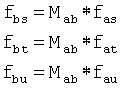
образует систему уравнений, по которой можно рассчитать Mab.forms a system of equations by which M ab can be calculated.
Mab согласно методу ПСД рассчитывается как оценка большого количества моментов времени для трех произвольно выбранных согласованных пар характеристических точек fa и fb. После того, как оценка Mab была рассчитана таким образом, ее снова проверяют в сравнении с другими согласованными парами характеристических точек в Pa и Pb. При этом определяется лучшая оценка Mab. Согласованные пары характеристических точек, которые согласно лучшей оценке Mab являются несовпадающими, отклоняются в качестве выбросов.M ab according to the PSD method is calculated as an estimate of a large number of time points for three arbitrarily selected matched pairs of characteristic points f a and f b . After the estimate of M ab was calculated in this way, it is again checked in comparison with other agreed pairs of characteristic points in P a and P b . In this case, the best score M ab is determined. Matched pairs of characteristic points that, according to the best estimate of M ab are mismatched, are rejected as outliers.
Благодаря использованию настоящего изобретения могут быть получены несколько благоприятных эффектов.By using the present invention, several beneficial effects can be obtained.
В периоды времени, когда изображения, полученные стереоскопической камерой 29, имеют плохое качество, можно все же отслеживать взаимное положение стереоскопической камеры (и, тем самым, комбайна) и целевой области, т.е. транспортной тележки.In periods of time when the images obtained by the
Можно надежно обнаруживать текущую поверхность материала в целевой области, т.е. продукции в транспортной тележке, и, тем самым, степень заполнения (тележки) или остаточный потенциал заполнения.It is possible to reliably detect the current surface of the material in the target area, i.e. products in the transport trolley, and, thus, the degree of filling (carts) or residual filling potential.
Кроме того, благодаря тому, что расположение края или его части определено, и информация об этом сохранена, по крайней мере, в предпочтительном варианте осуществления, можно отслеживать любой конец контейнера тележки, т.е. переднюю часть 51 с края и заднюю часть 51d края, после того, как соответствующая часть края оказалась в поле зрения камеры 29, даже если край 51 не попадает в поле зрения камеры целиком, т.е. не представлен в данном стереокадре, в любой момент времени.In addition, due to the fact that the location of the edge or part thereof is determined, and information about this is stored, at least in the preferred embodiment, it is possible to track any end of the trolley container, i.e. the
Claims (15)
получения эталонного кадра, который содержит трехмерную информацию о расположении, по меньшей мере, части целевой области (11);
идентификации ряда характеристических точек целевой области (11) в эталонном кадре;
получения от устройства формирования трехмерных изображений (29) нового кадра, отображающего, по меньшей мере, часть целевой области;
анализа нового кадра для идентификации ряда характеристических точек в новом кадре;
поиска и сопоставления характеристических точек в эталонном кадре и новом кадре;
анализа пар (53) согласованных характеристических точек для определения группы пар, демонстрирующих общее изменение расположения от эталонного кадра к новому кадру, и
формирования сигнала с учетом результатов последнего анализа.1. A control system for an agricultural vehicle, controlling a means (9) of transporting a product of an agricultural vehicle (1), in particular a discharge chute of a forage harvester, for supplying products to a target area (11), comprising a device (29) for generating three-dimensional images for receiving frames representing at least a portion of the target area, a data processor (46) and a memory device (46), said control system being configured to retrieve information from these frames to control the means of transporting the product (9), namely with the possibility of:
receiving a reference frame that contains three-dimensional information about the location of at least part of the target area (11);
identifying a number of characteristic points of the target area (11) in the reference frame;
receiving from the device for forming three-dimensional images (29) a new frame displaying at least a portion of the target area;
analysis of a new frame to identify a number of characteristic points in a new frame;
search and comparison of characteristic points in the reference frame and a new frame;
analyzing pairs (53) of consistent characteristic points to determine a group of pairs showing a general change in location from a reference frame to a new frame, and
signal generation taking into account the results of the last analysis.
получения эталонного кадра, который содержит трехмерную информацию о расположении, по меньшей мере, части целевой области (11);
идентификации ряда характеристических точек целевой области в эталонном кадре;
получения от устройства формирования трехмерных изображений (29) нового кадра, отображающего, по меньшей мере, часть целевой области;
анализа нового кадра для идентификации ряда характеристических точек в новом кадре;
поиска и сопоставления характеристических точек в эталонном кадре и новом кадре;
анализа пар (53) согласованных характеристических точек для определения группы пар, демонстрирующих общее изменение расположения от эталонного кадра к новому кадру, и
формирования сигнала с учетом результатов последнего анализа.14. An agricultural vehicle (1), containing a control system that controls the means (9) for transporting the product of an agricultural vehicle (1), in particular, the unloading trough of a forage harvester, for supplying products to the target area (11), while this system The control includes a device (29) for generating three-dimensional images for receiving frames displaying at least a portion of the target area, a data processor (46) and a memory device (46), said ION is configured to extract information from said frames to the control means (9) conveying the product, namely to:
receiving a reference frame that contains three-dimensional information about the location of at least part of the target area (11);
identification of a number of characteristic points of the target area in the reference frame;
receiving from the device for forming three-dimensional images (29) a new frame displaying at least a portion of the target area;
analysis of a new frame to identify a number of characteristic points in a new frame;
search and comparison of characteristic points in the reference frame and a new frame;
analyzing pairs (53) of consistent characteristic points to determine a group of pairs showing a general change in location from a reference frame to a new frame, and
signal generation taking into account the results of the last analysis.
получают эталонный кадр, который содержит трехмерную информацию о расположении, по меньшей мере, части целевой области (11);
идентифицируют ряд характеристических точек целевой области в эталонном кадре;
получают от устройства формирования трехмерных изображений (29) новый кадр, отображающий, по меньшей мере, часть целевой области;
анализируют новый кадр для идентификации ряда характеристических точек в новом кадре;
проводят поиск и сопоставляют характеристические точки в эталонном кадре и новом кадре;
анализируют пары (53) согласованных характеристических точек для определения группы пар, демонстрирующих общее изменение расположения от эталонного кадра к новому кадру, и
формируют сигнал с учетом результатов последнего анализа. 15. A control method by means of a control system of a means (9) for transporting a product of an agricultural vehicle (1), in particular a discharge chute of a forage harvester, for supplying products to a target area (11), said control system comprising a three-dimensional forming device (29) images to obtain frames representing at least part of the target area, a data processor (46) and a memory device (46), said control system being configured to extract information and h of the indicated frames for controlling the product transportation means (9), including the following steps:
receive a reference frame that contains three-dimensional information about the location of at least part of the target area (11);
identify a number of characteristic points of the target area in the reference frame;
receive from the device for forming three-dimensional images (29) a new frame that displays at least a portion of the target area;
analyze a new frame to identify a number of characteristic points in a new frame;
search and compare characteristic points in the reference frame and a new frame;
analyzing pairs (53) of matched characteristic points to determine a group of pairs showing a general change in location from a reference frame to a new frame, and
form a signal based on the results of the last analysis.
Applications Claiming Priority (4)
| Application Number | Priority Date | Filing Date | Title |
|---|---|---|---|
| EP20090169622 EP2301318B1 (en) | 2009-09-07 | 2009-09-07 | A control system of an agricultural vehicle with a goods carrier, an agricultural vehicle and a method of controlling a goods carrier of the agricultural vehicle |
| EP09169622.9 | 2009-09-07 | ||
| EP09170842.0 | 2009-09-21 | ||
| EP09170842A EP2311307B1 (en) | 2009-09-07 | 2009-09-21 | A filling degree gauge, an agricultural vehicle comprising such gauge, and a method of controlling filling of a target area |
Publications (2)
| Publication Number | Publication Date |
|---|---|
| RU2010135813A RU2010135813A (en) | 2012-03-10 |
| RU2520148C2 true RU2520148C2 (en) | 2014-06-20 |
Family
ID=43729301
Family Applications (1)
| Application Number | Title | Priority Date | Filing Date |
|---|---|---|---|
| RU2010135813/13A RU2520148C2 (en) | 2009-09-07 | 2010-08-30 | Control system for agricultural vehicle, agricultural vehicle and method of control of controlled means of product transportation |
Country Status (4)
| Country | Link |
|---|---|
| US (1) | US8656693B2 (en) |
| EP (1) | EP2311307B1 (en) |
| PL (1) | PL2311307T3 (en) |
| RU (1) | RU2520148C2 (en) |
Families Citing this family (83)
| Publication number | Priority date | Publication date | Assignee | Title |
|---|---|---|---|---|
| DE102007009666A1 (en) * | 2007-02-22 | 2008-08-28 | Carl Zeiss Microimaging Gmbh | Arrangement for filling a container with bulk material |
| ITBO20070461A1 (en) * | 2007-07-04 | 2009-01-05 | Dinamica Generale S R L | SYSTEM TO CHECK THE LOADING OF ONE OR MORE FOODS IN A MIXED MIXING UNIT BY MEANS OF A MECHANICAL SHOVEL MOUNTED ON A MOTOR VEHICLE |
| DE102008008260B4 (en) | 2008-02-08 | 2010-09-09 | Wirtgen Gmbh | Control of a mining machine and mining machine |
| DE102008002006A1 (en) * | 2008-05-27 | 2009-12-03 | Deere & Company, Moline | Control arrangement for controlling the transfer of agricultural crop from a harvester to a transport vehicle |
| DE102011052945A1 (en) * | 2011-08-24 | 2013-02-28 | Claas Selbstfahrende Erntemaschinen Gmbh | Agricultural harvester |
| DE102011114183A1 (en) * | 2011-09-22 | 2013-03-28 | Bomag Gmbh | Method for controlling a loading process of a transport vehicle with milled material, device for carrying out such a method and milling device |
| BE1020293A3 (en) | 2011-11-10 | 2013-07-02 | Cnh Belgium Nv | METHOD FOR SENDING A CAMERA SYSTEM ON AGRICULTURAL MACHINES |
| US8626406B2 (en) | 2011-12-22 | 2014-01-07 | Deere & Company | Method and system for transferring material between vehicles |
| US9861040B2 (en) * | 2012-02-10 | 2018-01-09 | Deere & Company | Method and stereo vision system for facilitating the unloading of agricultural material from a vehicle |
| US8649940B2 (en) | 2012-02-10 | 2014-02-11 | Deere & Company | Method and stereo vision system for managing the unloading of an agricultural material from a vehicle |
| US8868304B2 (en) | 2012-02-10 | 2014-10-21 | Deere & Company | Method and stereo vision system for facilitating the unloading of agricultural material from a vehicle |
| US9522792B2 (en) * | 2012-02-10 | 2016-12-20 | Deere & Company | System and method of material handling using one or more imaging devices on the transferring vehicle and on the receiving vehicle to control the material distribution into the storage portion of the receiving vehicle |
| US9392746B2 (en) | 2012-02-10 | 2016-07-19 | Deere & Company | Artificial intelligence for detecting and filling void areas of agricultural commodity containers |
| DE102012215005A1 (en) | 2012-08-23 | 2014-02-27 | Wirtgen Gmbh | Self-propelled milling machine, as well as method for steering a self-propelled milling machine |
| DE102012215013A1 (en) | 2012-08-23 | 2014-02-27 | Wirtgen Gmbh | Self-propelled milling machine, as well as method for unloading milled material |
| US9497898B2 (en) * | 2013-01-24 | 2016-11-22 | Tribine Industries, LLC | Agricultural harvester unloading assist system and method |
| US9313951B2 (en) * | 2013-04-02 | 2016-04-19 | Deere & Company | Optical image capture for controlling a position of a harvester transfer device |
| US9119342B2 (en) | 2013-04-22 | 2015-09-01 | Deere & Company, A Delaware Corporation | Methods for improving the robustness of an automated unloading system |
| EP2798939B1 (en) * | 2013-04-29 | 2018-06-20 | CLAAS E-Systems KGaA mbH & Co KG | Operating system for and method of operating a controllable transfer device for harvested goods |
| GB2517049B (en) | 2013-07-28 | 2019-09-11 | Deere & Co | Artificial intelligence for detecting and filling void areas of agricultural commodity containers |
| DE102013018724B4 (en) * | 2013-11-08 | 2015-09-03 | LASE Industrielle Lasertechnik GmbH | Agricultural harvester |
| BE1021167B1 (en) * | 2013-12-10 | 2016-01-14 | Cnh Industrial Belgium Nv | SENSOR SETUP |
| DE102014216603B4 (en) | 2014-08-21 | 2018-02-22 | Wirtgen Gmbh | Self-propelled milling machine, as well as method for unloading milled material |
| DE102014216713B4 (en) | 2014-08-22 | 2018-09-06 | Wirtgen Gmbh | Self-propelled milling machine, as well as method for unloading milled material |
| DE102014216763B4 (en) | 2014-08-22 | 2018-07-26 | Wirtgen Gmbh | Self-propelled milling machine, as well as method for unloading milled material |
| DE102015005194A1 (en) * | 2014-12-19 | 2016-06-23 | Bomag Gmbh | Milling material determination method and ground milling machine for carrying out the method |
| DE102015108055A1 (en) * | 2015-05-21 | 2016-11-24 | Claas Saulgau Gmbh | Method and control device for operating an agricultural loading wagon |
| AU2015230853B2 (en) * | 2015-09-28 | 2017-07-06 | Sandpit Innovation Pty Ltd | Method and system of payload optimisation |
| US20170130405A1 (en) * | 2015-11-05 | 2017-05-11 | Caterpillar Paving Products Inc. | Truck position control system for milling operations |
| US10019790B2 (en) | 2016-01-15 | 2018-07-10 | Deere & Company | Fill level indicator for an automated unloading system |
| US11242003B2 (en) * | 2016-01-21 | 2022-02-08 | Wirtgen Gmbh | System comprising construction machine, transport vehicle with loading space and image-recording device, and method for displaying an image stream during the loading or unloading of a transport vehicle |
| DE102016108902A1 (en) * | 2016-05-13 | 2017-11-16 | Claas Saulgau Gmbh | Method and control device for operating an agricultural transport vehicle and transport trolley |
| DE102016222589B4 (en) | 2016-11-16 | 2020-01-16 | Wirtgen Gmbh | Self-propelled milling machine and method for controlling a self-propelled milling machine |
| US10820492B2 (en) | 2016-12-12 | 2020-11-03 | Kubota Corporation | Work vehicle |
| DE102017113726A1 (en) * | 2017-06-21 | 2018-12-27 | Claas E-Systems Kgaa Mbh & Co Kg | Agricultural working machine |
| WO2019040946A1 (en) * | 2017-08-25 | 2019-02-28 | Nordsense, Inc. | Storage and collection systems and methods for use |
| DE102017220869A1 (en) | 2017-11-22 | 2019-05-23 | Wirtgen Gmbh | Self-propelled milling machine, method for automatically loading a means of transport with milled material, as well as road or soil treatment unit |
| US11358785B2 (en) * | 2018-04-04 | 2022-06-14 | Superior Bulk, Inc. | Silo system and bulk material management system |
| US11875522B2 (en) * | 2018-05-09 | 2024-01-16 | Trinamix Gmbh | Method and devices for determining a filling level in at least one storage unit |
| EP3586588B1 (en) * | 2018-06-22 | 2021-03-03 | Exel Industries | Vehicle for discharging crop and corresponding use |
| CN109282715A (en) * | 2018-09-21 | 2019-01-29 | 苏州市计量测试院 | A kind of calliper automatic measurement system and method |
| US11240961B2 (en) | 2018-10-26 | 2022-02-08 | Deere & Company | Controlling a harvesting machine based on a geo-spatial representation indicating where the harvesting machine is likely to reach capacity |
| US11653588B2 (en) | 2018-10-26 | 2023-05-23 | Deere & Company | Yield map generation and control system |
| US11589509B2 (en) | 2018-10-26 | 2023-02-28 | Deere & Company | Predictive machine characteristic map generation and control system |
| US11672203B2 (en) | 2018-10-26 | 2023-06-13 | Deere & Company | Predictive map generation and control |
| US11641800B2 (en) | 2020-02-06 | 2023-05-09 | Deere & Company | Agricultural harvesting machine with pre-emergence weed detection and mitigation system |
| US11178818B2 (en) | 2018-10-26 | 2021-11-23 | Deere & Company | Harvesting machine control system with fill level processing based on yield data |
| US11079725B2 (en) | 2019-04-10 | 2021-08-03 | Deere & Company | Machine control using real-time model |
| US11467605B2 (en) | 2019-04-10 | 2022-10-11 | Deere & Company | Zonal machine control |
| DE102019104218A1 (en) | 2019-02-19 | 2020-08-20 | Wirtgen Gmbh | Work train, comprising a tillage machine and another vehicle as well as an automated distance monitoring |
| US11234366B2 (en) | 2019-04-10 | 2022-02-01 | Deere & Company | Image selection for machine control |
| US11778945B2 (en) | 2019-04-10 | 2023-10-10 | Deere & Company | Machine control using real-time model |
| US11477940B2 (en) | 2020-03-26 | 2022-10-25 | Deere & Company | Mobile work machine control based on zone parameter modification |
| GB202011026D0 (en) * | 2020-07-17 | 2020-09-02 | Agco Int Gmbh | System and method of assisted or automated grain unload synchronization |
| GB202011027D0 (en) * | 2020-07-17 | 2020-09-02 | Agco Int Gmbh | System and method of assisted or automated grain unload synchronization |
| WO2022036114A1 (en) * | 2020-08-13 | 2022-02-17 | J. & M. Manufacturing Co., Inc. | Automated grain filling system and related methods |
| US11675354B2 (en) | 2020-10-09 | 2023-06-13 | Deere & Company | Machine control using a predictive map |
| US11895948B2 (en) | 2020-10-09 | 2024-02-13 | Deere & Company | Predictive map generation and control based on soil properties |
| US11871697B2 (en) | 2020-10-09 | 2024-01-16 | Deere & Company | Crop moisture map generation and control system |
| US11635765B2 (en) | 2020-10-09 | 2023-04-25 | Deere & Company | Crop state map generation and control system |
| US11874669B2 (en) | 2020-10-09 | 2024-01-16 | Deere & Company | Map generation and control system |
| US11889788B2 (en) | 2020-10-09 | 2024-02-06 | Deere & Company | Predictive biomass map generation and control |
| US11845449B2 (en) | 2020-10-09 | 2023-12-19 | Deere & Company | Map generation and control system |
| US11650587B2 (en) | 2020-10-09 | 2023-05-16 | Deere & Company | Predictive power map generation and control system |
| US11592822B2 (en) | 2020-10-09 | 2023-02-28 | Deere & Company | Machine control using a predictive map |
| US11474523B2 (en) | 2020-10-09 | 2022-10-18 | Deere & Company | Machine control using a predictive speed map |
| US11864483B2 (en) | 2020-10-09 | 2024-01-09 | Deere & Company | Predictive map generation and control system |
| US11946747B2 (en) | 2020-10-09 | 2024-04-02 | Deere & Company | Crop constituent map generation and control system |
| US11849672B2 (en) | 2020-10-09 | 2023-12-26 | Deere & Company | Machine control using a predictive map |
| US11927459B2 (en) | 2020-10-09 | 2024-03-12 | Deere & Company | Machine control using a predictive map |
| US11727680B2 (en) | 2020-10-09 | 2023-08-15 | Deere & Company | Predictive map generation based on seeding characteristics and control |
| US11825768B2 (en) | 2020-10-09 | 2023-11-28 | Deere & Company | Machine control using a predictive map |
| US11711995B2 (en) | 2020-10-09 | 2023-08-01 | Deere & Company | Machine control using a predictive map |
| US11844311B2 (en) | 2020-10-09 | 2023-12-19 | Deere & Company | Machine control using a predictive map |
| US11849671B2 (en) | 2020-10-09 | 2023-12-26 | Deere & Company | Crop state map generation and control system |
| US11889787B2 (en) | 2020-10-09 | 2024-02-06 | Deere & Company | Predictive speed map generation and control system |
| GB202020173D0 (en) * | 2020-12-18 | 2021-02-03 | Agco Int Gmbh | System and method of assisted or automated grain unload synchronization |
| US11765993B2 (en) | 2021-05-17 | 2023-09-26 | Deere & Company | Control system detecting fill level on receiving vehicle(s) |
| US20220397442A1 (en) | 2021-06-11 | 2022-12-15 | Deere & Company | Detecting and generating a rendering of fill level and distribution of material in receiving vehicle(s) |
| US11930738B2 (en) | 2021-06-28 | 2024-03-19 | Deere & Company | Closed loop control of filling mechanisms |
| US20230031013A1 (en) | 2021-07-28 | 2023-02-02 | Deere & Company | System for dynamically detecting alert conditions and optimization criteria |
| US11903344B2 (en) * | 2021-11-16 | 2024-02-20 | Cnh Industrial America Llc | System and method for controlling unloading system position of an agricultural harvester |
| US20230249925A1 (en) * | 2022-02-10 | 2023-08-10 | Jason Theodore Freadrich | Auger assembly |
Citations (5)
| Publication number | Priority date | Publication date | Assignee | Title |
|---|---|---|---|---|
| GB2073914A (en) * | 1980-03-31 | 1981-10-21 | Sperry Corp | Automatic spout control for agricultural machines |
| US6587772B2 (en) * | 2000-12-23 | 2003-07-01 | Claas Selbstfahrende Erntemaschinen Gmbh | Device for optimizing the transfer of harvested crop from a harvesting machine to a transport vehicle |
| RU2245611C2 (en) * | 1998-10-19 | 2005-02-10 | КЛААС Зельбстфаренде Эрнтемашинен ГмбХ | Reloading device control |
| RU2324323C2 (en) * | 2002-08-28 | 2008-05-20 | КЛААС Зельбстфаренде Эрнтемашинен ГмбХ | Device and way of management of cargo handling facilities (variants) and harvester with such device |
| RU2348142C2 (en) * | 2002-09-10 | 2009-03-10 | КЛААС Зельбстфаренде Эрнтемашинен ГмбХ | Method and device for control over operation of agricultural machine handling device and agricultural machine proper |
Family Cites Families (11)
| Publication number | Priority date | Publication date | Assignee | Title |
|---|---|---|---|---|
| DE4339441A1 (en) * | 1993-11-19 | 1995-05-24 | Incatronic Phoenix Mestechnik | Container filling level measuring system |
| DE4403893A1 (en) | 1994-02-08 | 1995-08-10 | Claas Ohg | Device for the automatic filling of loading containers with a stream of material |
| DE4426059C2 (en) | 1994-07-25 | 2001-07-05 | Case Harvesting Sys Gmbh | harvester |
| US6118427A (en) * | 1996-04-18 | 2000-09-12 | Silicon Graphics, Inc. | Graphical user interface with optimal transparency thresholds for maximizing user performance and system efficiency |
| DE19647522A1 (en) | 1996-11-16 | 1998-05-20 | Claas Ohg | Device for monitoring the overloading of goods from a working machine onto a transport vehicle |
| US6943824B2 (en) | 2002-03-13 | 2005-09-13 | Deere & Company | Image processing spout control system |
| DE102005018141A1 (en) * | 2005-04-20 | 2006-11-02 | Deere & Company, Moline | Grain tank with a rangefinder to detect the level |
| US7309048B2 (en) * | 2005-07-29 | 2007-12-18 | The Boeing Company | Vision system and method incorporating graphics symbology for use in a tanker refueling system |
| DE102007009666A1 (en) * | 2007-02-22 | 2008-08-28 | Carl Zeiss Microimaging Gmbh | Arrangement for filling a container with bulk material |
| ATE546991T1 (en) | 2007-08-03 | 2012-03-15 | Agrocom Gmbh & Co Agrarsystem Kg | AGRICULTURAL WORKING MACHINE |
| EP2138027B9 (en) * | 2008-06-25 | 2018-10-24 | CLAAS E-Systems KGaA mbH & Co KG | A transfering device and an agricultural vehicle |
-
2009
- 2009-09-21 EP EP09170842A patent/EP2311307B1/en active Active
- 2009-09-21 PL PL09170842T patent/PL2311307T3/en unknown
-
2010
- 2010-08-26 US US12/868,856 patent/US8656693B2/en active Active
- 2010-08-30 RU RU2010135813/13A patent/RU2520148C2/en active
Patent Citations (6)
| Publication number | Priority date | Publication date | Assignee | Title |
|---|---|---|---|---|
| GB2073914A (en) * | 1980-03-31 | 1981-10-21 | Sperry Corp | Automatic spout control for agricultural machines |
| RU2245611C2 (en) * | 1998-10-19 | 2005-02-10 | КЛААС Зельбстфаренде Эрнтемашинен ГмбХ | Reloading device control |
| US6587772B2 (en) * | 2000-12-23 | 2003-07-01 | Claas Selbstfahrende Erntemaschinen Gmbh | Device for optimizing the transfer of harvested crop from a harvesting machine to a transport vehicle |
| RU2282972C2 (en) * | 2000-12-23 | 2006-09-10 | КЛААС Зельбстфаренде Эрнтемашинен ГмбХ | Apparatus for optimized transfer of harvested mass onto farm vehicle (versions) |
| RU2324323C2 (en) * | 2002-08-28 | 2008-05-20 | КЛААС Зельбстфаренде Эрнтемашинен ГмбХ | Device and way of management of cargo handling facilities (variants) and harvester with such device |
| RU2348142C2 (en) * | 2002-09-10 | 2009-03-10 | КЛААС Зельбстфаренде Эрнтемашинен ГмбХ | Method and device for control over operation of agricultural machine handling device and agricultural machine proper |
Also Published As
| Publication number | Publication date |
|---|---|
| EP2311307A1 (en) | 2011-04-20 |
| US20110061762A1 (en) | 2011-03-17 |
| US8656693B2 (en) | 2014-02-25 |
| RU2010135813A (en) | 2012-03-10 |
| EP2311307B1 (en) | 2011-12-07 |
| PL2311307T3 (en) | 2012-09-28 |
Similar Documents
| Publication | Publication Date | Title |
|---|---|---|
| RU2520148C2 (en) | Control system for agricultural vehicle, agricultural vehicle and method of control of controlled means of product transportation | |
| RU2529905C2 (en) | Measuring device of filling degree, agricultural vehicle and method of control of filling target area | |
| US8682540B2 (en) | Method for directing an unloading apparatus of a harvesting machine to a container | |
| US9992931B2 (en) | Control arrangement and method for controlling a position of a transfer device of a harvesting machine | |
| US9992932B2 (en) | Control arrangement and method for controlling a position of a transfer device of a harvesting machine | |
| US10129528B2 (en) | Control arrangement and method for controlling a position of a transfer device of a harvesting machine | |
| EP3192345B1 (en) | Fill level indicator for an automated unloading system | |
| EP3062597B1 (en) | Unloading systems | |
| EP2368419B1 (en) | A method of detecting a structure in a field, a method of steering an agricultural vehicle and an agricultural vehicle | |
| CN103582907B (en) | Vehicle-mounted pattern recognition device and lane recognition method | |
| US7587081B2 (en) | Method for processing stereo vision data using image density | |
| US6744380B2 (en) | Apparatus for monitoring area adjacent to vehicle | |
| US11470776B2 (en) | Agricultural work machine | |
| US9655301B2 (en) | Unloading apparatus controller for agricultural harvesting machines | |
| US20100224140A1 (en) | Method and a System for Measuring an Animal's Height | |
| CN106326822A (en) | Method and device for detecting lane line | |
| WO2006028434A2 (en) | Method and apparatus for refining target position and size estimates using image and depth data | |
| JP2004012233A (en) | Apparatus and method for detecting agricultural product | |
| JPH11345392A (en) | Device and method for detecting obstacle | |
| EP3316218B1 (en) | Control arrangement and method for controlling a position of a transfer device of a harvesting machine | |
| CN115711128A (en) | Real-time abundance detection system and method for deep-sea polymetallic nodule mineral products | |
| EP3315007A1 (en) | Control arrangement and method for controlling a position of a transfer device of a harvesting machine | |
| CA2984976C (en) | Apparatus and method for the automated detection of trees |
Legal Events
| Date | Code | Title | Description |
|---|---|---|---|
| PD4A | Correction of name of patent owner | ||
| PD4A | Correction of name of patent owner | ||
| PD4A | Correction of name of patent owner |