RU2517103C2 - Improved controller of air flow - Google Patents
Improved controller of air flow Download PDFInfo
- Publication number
- RU2517103C2 RU2517103C2 RU2010117374/12A RU2010117374A RU2517103C2 RU 2517103 C2 RU2517103 C2 RU 2517103C2 RU 2010117374/12 A RU2010117374/12 A RU 2010117374/12A RU 2010117374 A RU2010117374 A RU 2010117374A RU 2517103 C2 RU2517103 C2 RU 2517103C2
- Authority
- RU
- Russia
- Prior art keywords
- louvre
- plates
- air flow
- rod
- plate
- Prior art date
Links
Images


Classifications
-
- F—MECHANICAL ENGINEERING; LIGHTING; HEATING; WEAPONS; BLASTING
- F24—HEATING; RANGES; VENTILATING
- F24F—AIR-CONDITIONING; AIR-HUMIDIFICATION; VENTILATION; USE OF AIR CURRENTS FOR SCREENING
- F24F13/00—Details common to, or for air-conditioning, air-humidification, ventilation or use of air currents for screening
- F24F13/08—Air-flow control members, e.g. louvres, grilles, flaps or guide plates
- F24F13/10—Air-flow control members, e.g. louvres, grilles, flaps or guide plates movable, e.g. dampers
- F24F13/14—Air-flow control members, e.g. louvres, grilles, flaps or guide plates movable, e.g. dampers built up of tilting members, e.g. louvre
- F24F13/15—Air-flow control members, e.g. louvres, grilles, flaps or guide plates movable, e.g. dampers built up of tilting members, e.g. louvre with parallel simultaneously tiltable lamellae
-
- F—MECHANICAL ENGINEERING; LIGHTING; HEATING; WEAPONS; BLASTING
- F24—HEATING; RANGES; VENTILATING
- F24F—AIR-CONDITIONING; AIR-HUMIDIFICATION; VENTILATION; USE OF AIR CURRENTS FOR SCREENING
- F24F11/00—Control or safety arrangements
- F24F11/70—Control systems characterised by their outputs; Constructional details thereof
- F24F11/72—Control systems characterised by their outputs; Constructional details thereof for controlling the supply of treated air, e.g. its pressure
- F24F11/74—Control systems characterised by their outputs; Constructional details thereof for controlling the supply of treated air, e.g. its pressure for controlling air flow rate or air velocity
- F24F11/745—Control systems characterised by their outputs; Constructional details thereof for controlling the supply of treated air, e.g. its pressure for controlling air flow rate or air velocity the air flow rate increasing with an increase of air-current or wind pressure
Landscapes
- Engineering & Computer Science (AREA)
- Physics & Mathematics (AREA)
- Fluid Mechanics (AREA)
- Chemical & Material Sciences (AREA)
- Combustion & Propulsion (AREA)
- Mechanical Engineering (AREA)
- General Engineering & Computer Science (AREA)
- Air-Flow Control Members (AREA)
- Specific Sealing Or Ventilating Devices For Doors And Windows (AREA)
- Power-Operated Mechanisms For Wings (AREA)
Abstract
Description
Настоящее изобретение относится к улучшенному регулятору воздушного потока, в частности, к такому регулятору воздушного потока жалюзийного типа, который может быть использован в горных шахтах, туннелях, штольнях, штреках и подобном, далее называемых проходами в шахте, для управления или регулирования воздушного потока, проходящего через них.The present invention relates to an improved air flow regulator, in particular, to such a louvre type air flow regulator, which can be used in mining mines, tunnels, adits, drifts and the like, hereinafter referred to as mine passages, for controlling or regulating the air flow passing Through them.
Подземные шахты обычно имеют некоторое количество штолен, которые функционируют, как каналы для свежего воздуха, причем штольни часто образуются на стороне входа воздуха рудного тела и на стороне выхода воздуха, или на противоположной стороне рудного тела. Поток воздуха на разных уровнях в шахте или, в случае металлосодержащих шахт, в отдельных областях шахты, называемых забоями, таким образом, управляется регуляторами воздушного потока, расположенными, в частности, у входов или выходов этих штолен.Underground mines usually have a number of tunnels that function as fresh air channels, more often the tunnels are formed on the air inlet side of the ore body and on the air outlet side, or on the opposite side of the ore body. The air flow at different levels in the mine or, in the case of metal-containing mines, in separate areas of the mine, called faces, is thus controlled by air flow regulators located, in particular, at the entrances or exits of these adits.
Известные регуляторы воздушного потока, использующиеся в шахтах, называются регуляторами с опускаемыми досками ('drop-board regulator') и используются уже некоторое время. Регуляторы с опускаемыми досками обычно содержат стальную Н-образную раму, изготовленную из отсеков подходящего размера. В каждый отсек опускаются деревянные доски между фланцами Н-образного сечения. Таким образом, отверстие регулятора может быть отрегулировано по площади, таким образом, изменяя количество потока воздуха, которое допускается в данную секцию шахты.The well-known airflow regulators used in mines are called drop-board regulators and have been used for some time. Regulators with lowering boards usually contain a steel H-shaped frame made of compartments of a suitable size. Wooden boards are lowered into each compartment between the flanges of the H-shaped section. Thus, the hole of the regulator can be adjusted in area, thus changing the amount of air flow that is allowed in this section of the shaft.
Тем не менее, регуляторы с опускаемыми досками требуют ручной регулировки. К тому же, перед возникновением такого события, как пожар в забое или взрыв, и если предполагается, что взрыв может физически повредить регулятор, шахтер должен физически удалить все доски из регулятора. Это является тяжелой, трудной и отнимающей много времени задачей, которая приводит к растрате человеко-часов и уменьшает эффективность шахты.However, knob controls require manual adjustment. In addition, before the occurrence of an event such as a downhole fire or explosion, and if it is assumed that the explosion could physically damage the regulator, the miner must physically remove all the boards from the regulator. This is a difficult, arduous and time-consuming task, which leads to waste of man-hours and reduces the efficiency of the mine.
В документе WO2006/108228, полное содержание которого включено в этот документ по ссылке, раскрывается улучшенный регулятор воздушного потока жалюзийного типа, в котором воздушный поток управляется посредством регулирования степени открытия жалюзийных пластин, которые могут свободно поворачиваться в полностью открытое положение во время взрыва или пожара в забое, но могут возвращаться в начальные положения после такого пожара посредством веса, газовой стойки или пружины.WO2006 / 108228, the entire contents of which is incorporated herein by reference, discloses an improved louvre-type air flow regulator in which the air flow is controlled by controlling the degree of opening of the louvre plates, which can freely rotate to a fully open position during an explosion or fire in face, but can return to their original positions after such a fire by means of a weight, gas strut or spring.
Настоящее изобретение относится к улучшениям регуляторов воздушного потока, раскрытых в документе WO2006/108228.The present invention relates to improvements in air flow regulators disclosed in WO2006 / 108228.
Любое обсуждение документов, действий, материалов, устройств, изделий или подобного, которые были включены в настоящее описание, направлено исключительно на обеспечение контекста для настоящего изобретения. Не следует принимать за допущение, что любые или все эти объекты образуют часть базы предшествующего уровня техники или являлись общими знаниями в области техники, относящейся к настоящему изобретению, существовавшей до даты приоритета каждого пункта формулы изобретения настоящей заявки.Any discussion of documents, acts, materials, devices, products, or the like that are included in the present description is intended solely to provide a context for the present invention. It should not be assumed that any or all of these objects form part of the prior art base or were general knowledge of the technical field related to the present invention that existed prior to the priority date of each claim of the present application.
Согласно изобретению разработан регулятор воздушного потока для прохода в шахте, содержащий:According to the invention, an air flow regulator for passage in a mine is developed comprising:
жалюзийную пластину, выполненную с возможностью поворота в заданное положение, которое находится в диапазоне от закрытого положения, в котором жалюзийная пластина ограничивает, по меньшей мере, часть прохода, до открытого положения, в котором воздух может свободно течь в проходе; иa louvre plate configured to rotate to a predetermined position that is in a range from a closed position in which the louvre plate delimits at least a portion of the passage to an open position in which air can flow freely in the passage; and
связующий механизм для поворота жалюзийной пластины, причем связующий механизм включает в себя механизм смещающей стойки, который только приводится в действие, для поворота жалюзийной пластины в открытое положение, когда достигается заданный воздушный поток, и подпирает жалюзийную пластину в ее заданное положение, после того, как воздушный поток становится меньше, чем заданный воздушный поток.a linking mechanism for rotating the louvre plate, the linking mechanism including a biasing mechanism that is only actuated to rotate the louvre plate to the open position when a predetermined air flow is reached, and rests the louvre plate in its predetermined position after airflow becomes smaller than a given airflow.
Механизм смещающей стойки образует часть связующего механизма, будучи не приведенным в действие, и является, в целом, выполненным с возможностью перемещения со связующим механизмом, будучи не приведенным в действие, и, таким образом, он позволяет жалюзийным пластинам перемещаться между открытым и закрытым положениями без необходимости существенного приложения силы. В отличие от этого, в вариантах осуществления, описанных в документе WO2006/108228, которые включают в себя газовую стойку, невозможно поворачивать жалюзийные пластины без приведения в действие газовой стойки. Таким образом, настоящее изобретение является значительным улучшением предшествующего уровня техники, так как это значит, что степень вентиляции может быть легко изменена без необходимости приложения слишком большой силы к связующему механизму. Это устройство является особенно преимущественным, так как оно позволяет регулятору воздушного потока быть легко автоматизированным, например, посредством предусмотрения механизированного привода для перемещения механизма стойки. Таким образом, в изобретении разработан регулятор воздушного потока, который имеет такое же усилие, как регуляторы предшествующего уровня техники, но имеет уменьшенный вес и является более гибким в своей работе. Благодаря уменьшению веса регуляторы воздушного потока, выполненные согласно настоящему изобретению, являются более простыми в транспортировке и установке.The biasing mechanism of the strut forms part of the coupling mechanism, when not actuated, and is generally configured to move with the coupling mechanism, not being actuated, and thus allows the louvre plates to move between open and closed positions without the need for a substantial application of force. In contrast, in the embodiments described in WO2006 / 108228, which include a gas strut, it is not possible to rotate the louvre plates without activating the gas strut. Thus, the present invention is a significant improvement of the prior art, as this means that the degree of ventilation can be easily changed without the need for too much force to be applied to the coupling mechanism. This device is particularly advantageous since it allows the air flow regulator to be easily automated, for example, by providing a mechanized drive to move the rack mechanism. Thus, the invention developed an air flow regulator that has the same force as the prior art regulators, but has a reduced weight and is more flexible in its operation. Due to the weight reduction, the air flow regulators according to the present invention are easier to transport and install.
В некоторых вариантах осуществления регулятор может содержать множество жалюзийных пластин. В некоторых вариантах осуществления регулятор может являться входным регулятором и может содержать множество жалюзийных пластин, которые перекрываются в закрытом положении для закрытия или ограничения, по меньшей мере, части прохода. В некоторых вариантах осуществления регулятор может являться выходным регулятором и может содержать множество жалюзийных пластин, которые не перекрываются в закрытом положении.In some embodiments, the controller may comprise a plurality of louvres. In some embodiments, the controller may be an input controller and may comprise a plurality of louvre plates that overlap in a closed position to close or restrict at least a portion of the passage. In some embodiments, the controller may be an output controller and may comprise a plurality of louvre plates that do not overlap in the closed position.
В некоторых вариантах осуществления регулятор может содержать раму, в которой установлена жалюзийная пластина. Жалюзийная пластина может быть установлена в раме таким образом, чтобы она могла поворачиваться в ней вокруг продольной оси. Преимущество наличия рамы заключается в том, что регулятор является простым в изготовлении, транспортировке и установке.In some embodiments, the controller may comprise a frame in which a louvre plate is mounted. The louvre plate can be installed in the frame so that it can rotate around it along the longitudinal axis. The advantage of having a frame is that the regulator is easy to manufacture, transport and install.
В некоторых вариантах осуществления механизм подпирающей стойки может являться механизмом смещающей стойки постоянной силы, который приводится в действие только тогда, когда была достигнута заданная постоянная сила, например, от воздушного потока, прилагающего силу к жалюзийной пластине, которая присоединена к механизму стойки посредством связующего механизма. Механизм подпирающей стойки может приводиться в действие от сжатия. Заданная постоянная сила может быть выбрана со значением в диапазоне от максимального количества силы, требуемого для перемещения жалюзийных пластин до силы, образуемой заданным воздушным потоком. Специалист в данной области техники легко определит подходящую силу, при которой механизм смещающей стойки приведется в действие. Заданный воздушный поток может являться воздушным потоком или изменением давления от умышленного или случайного взрыва в шахте, например, от взрыва или пожара в забое. Механизм смещающей стойки может содержать стойку с текучей средой, например, газовую стойку. Механизм смещающей стойки может содержать пружину. В некоторых вариантах осуществления механизм стойки приводится в действие только тогда, когда к нему прилагается сила, превышающая 4000 ньютонов, тем не менее, сила может быть изменена для соответствия требуемому проекту воздушного потока.In some embodiments, the support strut mechanism may be a constant force bias mechanism, which is only activated when a predetermined constant force has been achieved, for example, from an air flow exerting force on a louvre plate that is connected to the rack mechanism via a linking mechanism. The support rack mechanism may be driven by compression. The predetermined constant force can be selected with a value in the range from the maximum amount of force required to move the louvre plates to the force generated by the given air flow. One of ordinary skill in the art will easily determine the appropriate force at which the biasing strut mechanism is actuated. The predetermined air stream may be an air stream or a change in pressure from a deliberate or accidental explosion in a mine, for example, from an explosion or a fire in the face. The biasing rack mechanism may comprise a fluid rack, such as a gas strut. The biasing mechanism may include a spring. In some embodiments, the rack mechanism is only actuated when a force of more than 4000 Newtons is applied to it, however, the force can be changed to fit the desired airflow design.
В некоторых вариантах осуществления связующий механизм может включать в себя связующую штангу, которая функционально соединена с жалюзийной пластиной посредством связующего рычага. Например, один конец связующего рычага может быть прикреплен к жалюзийной пластине, а другой его конец присоединен с возможностью поворота к связующей штанге для подпора жалюзийных пластин в заданное положение. В некоторых вариантах осуществления связующая штанга может быть ориентирована вертикально.In some embodiments, the coupling mechanism may include a coupling rod that is operatively connected to the louvre plate by means of a coupling lever. For example, one end of the link arm can be attached to the louvre plate, and the other end is pivotally connected to the link bar to support the louvre plates in a predetermined position. In some embodiments, the tie rod may be oriented vertically.
В некоторых вариантах осуществления связующий механизм имеет выборочно изменяющуюся длину, причем регулятор выполнен таким образом, чтобы жалюзийная пластина находилась в закрытом положении, когда связующий механизм имеет максимальную длину, и чтобы жалюзийная пластина находилась в открытом положении, когда связующий механизм имеет минимальную длину.In some embodiments, the bonding mechanism has a selectively varying length, the controller being configured so that the louvre plate is in the closed position when the bonding mechanism has a maximum length, and so that the louvre plate is in the open position when the bonding mechanism has a minimum length.
В некоторых вариантах осуществления связующий механизм имеет механизм управления положением для выборочного изменения длины связующего механизма. Механизм управления положением может быть управляемым вручную. Например, он может содержать стержень с наружной резьбой, расположенный над полой стойкой, и рукояткой и резьбовой муфтой, выполненной таким образом, чтобы посредством поворота рукоятки стержень с резьбой мог быть поднят или опущен в полую стойку. Механизм управления положением может быть автоматизированным, например, он может быть выполнен в форме механизированного привода, приводимого в действие сжатым воздухом, электрически или гидравлически. Привод может также содержать механизм управления положением, управляемый вручную. Связующий механизм может иметь минимальную длину посредством приведения в действие механизма смещающей стойки или посредством работы механизма управления положением.In some embodiments, the binder mechanism has a position control mechanism for selectively changing the length of the binder mechanism. The position control mechanism may be manually controlled. For example, it may comprise an external threaded rod located above the hollow post and a handle and threaded sleeve so that the threaded rod can be raised or lowered into the hollow post by turning the handle. The position control mechanism may be automated, for example, it may be in the form of a mechanized drive driven by compressed air, electrically or hydraulically. The actuator may also include a manually controlled position control mechanism. The coupling mechanism may have a minimum length by actuating the biasing strut mechanism or by operating the position control mechanism.
В некоторых вариантах осуществления механизированный привод может управляться дистанционно. Использование дистанционного управления особенно полезно, если регулятор воздушного потока расположен в местоположении, являющемся труднодоступным или небезопасным для доступа из-за загрязненного воздуха. Более того, дистанционное управление может значительно увеличить скорость, с которой может быть изменена степень вентиляции. Это приводит к улученной безопасности и эффективности.In some embodiments, the motorized drive may be remotely controlled. Using the remote control is especially useful if the airflow regulator is located in a location that is difficult to access or insecure due to air pollution. Moreover, remote control can significantly increase the speed at which the degree of ventilation can be changed. This results in improved safety and efficiency.
В некоторых вариантах осуществления механизм смещающей стойки предусмотрен между связующей штангой и механизмом управления положением. Например, один конец механизма смещающей стойки, обычно, конец с цилиндром, может быть прикреплен к связующей штанге посредством кронштейна или подобного, прикрепленного к связующей штанге таким образом, чтобы перемещение связующей штанги перемещало этот конец механизма смещающей стойки. Конец с цилиндром может быть прикреплен с возможностью поворота к связующей штанге. Поршневой шток может быть прикреплен к механизму управления положением.In some embodiments, a biasing rack mechanism is provided between the tie rod and the position control mechanism. For example, one end of the bias rack mechanism, typically the end with a cylinder, may be attached to the tie rod by a bracket or the like attached to the tie rod so that the movement of the tie rod moves this end of the shift beam mechanism. The end with the cylinder can be pivotally attached to the tie rod. The piston rod may be attached to the position control mechanism.
Таким образом, в широком смысле, в настоящем изобретении разработан регулятор воздушного потока жалюзийного типа, который обеспечивает непрерывное позиционное регулирование жалюзийных пластин и использует механизм стойки предпочтительно постоянной силы для возвратного перемещения пластин, который является относительно не сжатым в состоянии покоя.Thus, in a broad sense, the present invention has developed a louvre type airflow regulator that provides continuous positional control of the louvre plates and uses a rack mechanism, preferably of constant force, to return the plates, which is relatively uncompressed at rest.
Согласно изобретению дополнительно разработан регулятор воздушного потока жалюзийного типа для прохода в шахте, содержащий:According to the invention, a louvre-type air flow regulator for passage in a mine is further developed, comprising:
множество жалюзийных пластин, установленных в раме и поворачивающихся в ней вокруг продольной оси между заданным положением, в котором жалюзийные пластины объединяются для закрытия или ограничения, по меньшей мере, части прохода, и открытым положением, в котором воздух может свободно течь между жалюзийными пластинами и через часть прохода; иa plurality of louvre plates installed in the frame and pivoting therein around a longitudinal axis between a predetermined position in which the louvre plates are combined to close or limit at least a portion of the passage and an open position in which air can freely flow between the louvre plates and through part of the passage; and
причем, когда достигается заданный поток воздуха, жалюзийные пластины располагаются для открытия или дальнейшего открытия до тех пор, пока не откроются полностью, и включают в себя возвратный механизм, заставляющий пастины возвращаться в их заданное положение после того, как воздушный поток станет меньше, чем заданный воздушный поток, иmoreover, when a predetermined air flow is reached, the louvre plates are arranged to open or further open until they are fully opened, and include a return mechanism forcing the pastes to return to their predetermined position after the air flow becomes smaller than the predetermined air flow, and
причем возвратный механизм включает в себя смещающее средство в форме механизма стойки, который функциональное соединен со связующим механизмом, который воздействует на одну или более жалюзийных пластин для смещения их в заданное положение, и причем возвратный механизм выполнен таким образом, что механизм стойки не приводится в действие за исключением того, когда пластины открываются после достижения заданного воздушного потока.moreover, the return mechanism includes biasing means in the form of a rack mechanism, which is operatively connected to a coupling mechanism that acts on one or more louvre plates to bias them to a predetermined position, and wherein the return mechanism is designed so that the rack mechanism is not actuated except when the plates open after reaching a predetermined air flow.
Обычно механизм стойки является газовой стойкой, содержащей цилиндр, поршень и поршневой шток.Typically, the strut mechanism is a gas strut containing a cylinder, piston, and piston rod.
Газовая стойка предпочтительно является механизмом стойки постоянной силы, который перемещается/приводится в действие только тогда, когда к нему прилагается сила, превосходящая 4000 ньютонов, или некая другая заданная сила.The gas strut is preferably a constant force strut mechanism that only moves / operates when a force exceeding 4000 Newtons or some other predetermined force is applied to it.
Возвратный механизм может включать в себя вертикально ориентированную связующую штангу, которая функционально соединена с каждой жалюзийной пластиной посредством связующего рычага, один конец которого прикреплен к жалюзийным пластинам, а другой конец которого присоединен с возможностью поворота к связующей штанге.The return mechanism may include a vertically oriented connecting rod that is operatively connected to each louvre plate by means of a connecting lever, one end of which is attached to the louvre plates, and the other end of which is rotatably connected to the connecting rod.
Предпочтительно один конец газовой стойки, обычно, конец с цилиндром, присоединен с возможностью поворота к связующей штанге посредством кронштейна, или подобного, прикрепленного к штанге таким образом, чтобы перемещение штанги перемещало этот конец стойки.Preferably, one end of the gas strut, typically the end with a cylinder, is rotatably attached to the connecting rod by a bracket, or the like, attached to the rod so that moving the rod moves this end of the strut.
Свободный конец поршневого штока предпочтительно присоединен с возможностью поворота к средству для поднятия и опускания этого конца и, следовательно, к связующей штанге.The free end of the piston rod is preferably rotatably connected to a means for raising and lowering this end and, therefore, to the connecting rod.
В одном предпочтительном варианте осуществления средство является стержнем с наружной резьбой, расположенным над полой стойкой, и рукояткой и резьбовой муфтой, причем поворот рукоятки поднимает и опускает стержень с резьбой.In one preferred embodiment, the means is an external threaded rod located above the hollow post and a handle and threaded sleeve, the rotation of the handle raising and lowering the threaded rod.
Термин “заданный воздушный поток” может включать в свой объем заданное давление воздуха и, обычно, тем не менее, не исключительно, относится к увеличению воздушного потока/давления из-за взрывов/пожара в забое.The term “predetermined air flow” may include a predetermined air pressure in its volume and, usually, however, not exclusively, refers to an increase in air flow / pressure due to explosions / fire in the face.
Воздушный поток будет, как правило, воздействовать на лопасти из-за воздушных потоков, которые могут течь в любом направлении через регулятор. Тем не менее, эти потоки нормального вентиляционного воздуха, как правило, не будут иметь достаточной силы для того, чтобы заставить жалюзийные пластины перемещаться.The airflow will typically affect the blades due to airflows that can flow in any direction through the regulator. However, these flows of normal ventilation air will generally not have sufficient force to cause the louvres to move.
Конкретные варианты осуществления настоящего изобретения будут описаны далее только для примера со ссылкой на прилагаемые чертежи, в которых:Specific embodiments of the present invention will now be described, by way of example only, with reference to the accompanying drawings, in which:
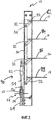
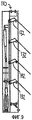
Фиг.1 представляет собой вид спереди регулятора жалюзийного типа согласно первому варианту осуществления изобретения с пластинами в открытом положении;Figure 1 is a front view of a louvre-type regulator according to a first embodiment of the invention with plates in an open position;
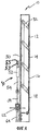
Фиг.2 представляет собой вид сверху регулятора жалюзийного типа, изображенного на фиг.1;Figure 2 is a top view of the louvre type controller shown in figure 1;
Фиг.3 представляет собой вид сбоку регулятора жалюзийного типа, изображенного на фиг.1, с пластинами в полностью открытом положении;FIG. 3 is a side view of the louvre type controller of FIG. 1 with plates in a fully open position;
Фиг.4 представляет собой вид сбоку регулятора жалюзийного типа, изображенного на фиг.1, с пластинами в полностью закрытом положении;FIG. 4 is a side view of a louvre type controller of FIG. 1 with plates in a fully closed position;
Фиг.5 представляет собой вид сбоку регулятора, изображенного на фиг.1, с пластинами в частично открытом положении в результате действия воздушного потока или ручной регулировки;FIG. 5 is a side view of the controller of FIG. 1 with plates in a partially open position as a result of air flow or manual adjustment;
Фиг.6 представляет собой вид сбоку регулятора, изображенного на фиг.5, с пластинами, открытыми еще больше.Fig.6 is a side view of the regulator depicted in Fig.5, with the plates open even more.
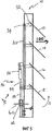
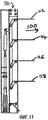
Фиг.7 представляет собой вид спереди автоматизированного регулятора жалюзийного типа согласно второму варианту осуществления изобретения;7 is a front view of an automated louvre type controller according to a second embodiment of the invention;
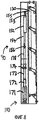
Фиг.8 представляет собой вид сбоку регулятора жалюзийного типа, изображенного на фиг.7, с пластинами в стандартном закрытом положении;Fig. 8 is a side view of the louvre type controller of Fig. 7 with plates in a standard closed position;
Фиг.9 представляет собой вид сбоку регулятора жалюзийного типа, изображенного на фиг.7, с пластинами на половине пути между открытым и закрытым положениями;FIG. 9 is a side view of the louvre type controller of FIG. 7, with plates halfway between the open and closed positions;
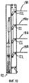
Фиг.10 представляет собой вид сбоку регулятора жалюзийного типа, изображенного на фиг.7, с пластинами в стандартном открытом положении;FIG. 10 is a side view of the louvre type controller of FIG. 7 with plates in a standard open position;
Фиг.11 представляет собой вид сбоку регулятора жалюзийного типа, изображенного на фиг.7, с пластинами во взрывном открытом положении; и11 is a side view of the louvre-type controller of FIG. 7 with plates in an explosive open position; and
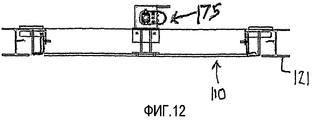
Фиг.12 представляет собой вид в плане регулятора жалюзийного типа, изображенного на фиг.7.Fig. 12 is a plan view of a louvre type controller of Fig. 7.
Обратимся теперь к чертежам, на фиг.1-4 изображен жалюзийный регулятор 10, или модуль, согласно первому варианту осуществления изобретения для установки в проходе шахты. Регулятор 10 содержит множество пластин 12, 14, 16 и 18 жалюзи, установленных в прямоугольной стальной раме 20. Рама 20 выполнена с возможностью подгонки в место нахождения рамы 21 регулятора с опускаемыми досками (см. фиг.2). Тем не менее, он также может быть изготовлен в новой раме для установки в отверстия шахты.Turning now to the drawings, FIGS. 1-4 show a
Каждая пластина 12, 14, 16, 18 жалюзи установлена у своих противоположных концов в раме 20 и выполнена с возможностью поворота вокруг своей продольной оси 22 между закрытым или частично закрытым положением, в котором пластины 12, 14, 16, 18 жалюзи объединяются для закрытия или ограничения потока газа, по меньшей мере, через часть прохода, и открытым положением, в котором газ, обычно, воздух, способен более легко протекать между пластинами 12, 14, 16, 18 жалюзи и через проход. Как лучше всего видно на фиг.3, ось 22 образована штангой 22 и установлена в нем. Штанга 22, установленная, обычно, посредством сварки, сзади пластин 12, 14, 16, 18 жалюзи и вблизи от их верхней кромки.Each
Как лучше всего видно на фиг.4, пластины 12, 14, 16, 18 жалюзи перекрываются в закрытом положении, что является особенно полезным для входного жалюзийного регулятора, так как результатом этого является образование уплотнения благодаря давлению воздуха, вентилирующего проход, на лицевые стороны 82, 84, 86, 88 жалюзийных пластин. Также возможно использовать неперекрывающееся устройство для выходного жалюзийного регулятора.As best seen in FIG. 4, the
Предусмотрен механизм 90 регулирования и смещения для воздействия на каждую пластину 12, 14, 16, 18 жалюзи.A control and biasing mechanism 90 is provided for acting on each
Механизм 90 регулирования и смещения включает в себя вертикальную связующую штангу 30, которая присоединена к каждой пластине 12, 14, 16, 18 жалюзи посредством связующих рычагов 32 в форме двойного кронштейна, один конец которых присоединен (посредством сварки) к пластинам 12, 14, 16, 18 жалюзи, а другой конец которых прикреплен посредством соответствующего соединительного шарнира 34 к связующей штанге 30.The adjustment and biasing mechanism 90 includes a vertical connecting
Механизм 90 смещения включает в себя газовую стойку 50 постоянной силы, включающую в себя цилиндр 52 и поршневой шток 54. Газовая стойка 50 выполнена с возможностью приведения в действие (то есть, поршневой шток 54 перемещается в цилиндр 52, сжимая газ внутри), когда сила взрыва, воздействующая на жалюзийные пластины, передает силу через связующую штангу (обычно, составляющую 4000 ньютонов или более) и прилагается к поршневому штоку 54. Конец 53 цилиндра газовой стойки 50 присоединен с возможностью поворота к связующей штанге 30 посредством кронштейна, или скобы 55, или подобного, прикрепленного к штанге 30 таким образом, чтобы перемещение штанги 30 перемещало этот конец стойки 50, и наоборот.The biasing mechanism 90 includes a constant-
Свободный конец 56 поршневого штока 54 присоединен с возможностью поворота к стержню 59 с наружной резьбой. Механизм 58 управления положением, который включает в себя рукоятку 60 в форме крестообразно пересекающихся рычагов или колеса, прикреплен к муфте 62 с внутренней резьбой, расположенной над полой стойкой 64.The
Во время использования поворачивание рукоятки/рычагов 60 в одном направлении (по часовой стрелке или против часовой стрелки) заставит стержень 59 с резьбой подниматься вертикально и, в то же время, толкать вверх поршневой шток 54 газовой стойки 50 против веса связующей штанги 30. Вес связующей штанги 30 не является достаточным для сжатия газовой штанги 50. Когда модуль 10 находится в “состоянии покоя” (“at rest”), то есть, не во время взрыва или во все время, когда поток воздуха находится ниже заданного уровня, в полностью открытом положении, изображенном на фиг.3, или в полностью закрытом положении, изображенном на фиг.4, или в любом промежуточном положении, газовая стойка 50 постоянной силы не сжата. Это делает регулирование пластин 12, 14, 16, 18 жалюзи более легким и безопасным, так как газовая стойка 50 не должна быть сжата или разжата по мере осуществления регулирования пластин 12, 14, 16, 18 жалюзи для изменения степени вентиляции. Регулирование также является непрерывным между полностью открытым и полностью закрытым положениями посредством простого вращения рукоятки/рычагов 60 для установки пластин 12, 14, 16, 18 жалюзи для обеспечения требуемого количества вентиляции.During use, turning the handle /
Теперь обратимся к фиг.4 и 5, газовая стойка 50 становится сжатой только во время сильно увеличенного воздушного потока 100, такого, который случается во время взрыва или пожара в забое, когда положение стержня 59 с резьбой остается неизменным, а пластины 12, 14, 16, 18 жалюзи поворачиваются в направлении “A” против часовой стрелки, или вверх, толкая поршневой шток 54 в цилиндр 52 и сжимая газовую стойку 50. Такое воздействие обеспечивает подпор для возврата пластин 12, 14, 16, 18 жалюзи в их установленное положение после того, как сильно увеличенный воздушный поток 100 ослабеет после пожара.Now referring to Figs. 4 and 5, the
На фиг.7-12 изображен второй вариант осуществления жалюзийного регулятора 110 согласно настоящему изобретению. Жалюзийный регулятор 110 представляет собой автоматизированный жалюзийный регулятор, в котором управляемый вручную механизм 58 первого варианта осуществления для регулирования положения стойки 50 заменен на механизированный привод. Признаки второго варианта осуществления, подобные признакам первого варианта осуществления, обозначены подобными номерами.7-12 show a second embodiment of a
Жалюзийный регулятор 110 содержит множество пластин 112, 114, 116, 118 жалюзи, установленных в прямоугольной стальной раме 120. Рама 120 выполнена с возможностью подгонки в место нахождения рамы 121 регулятора с опускаемыми досками, изображенной на фиг.12. Тем не менее, регулятор 110 также может быть изготовлен в новой раме (не изображена) для установки в отверстия шахты. Каждая пластина 112, 114, 116, 118 жалюзи установлена у своих противоположных концов (один из которых обозначен номером 122а на фиг.7) в раме 120 и выполнена с возможностью поворота вокруг своей продольной оси 122 между закрытым или частично закрытым положением (так, как изображено на фиг.7 и 8), в котором пластины 112, 114, 116, 118 жалюзи объединяются для закрытия или ограничения потока газа, по меньшей мере, через часть прохода, и открытым положением (изображенном на фиг.10 и 11), в котором газ, обычно, воздух, способен более легко течь между пластинами 112, 114, 116, 118 жалюзи и через проход. Ось 122 определена посредством/находится в штанге 122, установленной, обычно, посредством сварки, сзади пластин 112, 114, 116, 118 жалюзи и вблизи от их верхней кромки.The
Как лучше всего видно на фиг.8, пластины 112, 114, 116, 118 жалюзи перекрываются в закрытом положении, что является особенно полезным для входного жалюзийного регулятора, так как результатом этого является образование уплотнения благодаря давлению воздуха, вентилирующего проход, на лицевые стороны 182, 184, 186, 188 жалюзийных пластин. Также возможно использовать неперекрывающееся устройство для выходного жалюзийного регулятора.As best seen in FIG. 8, the
Предусмотрен механизм 190 регулирования и смещения для воздействия на каждую пластину 112, 114, 116, 118 жалюзи.A control and
Механизм 190 регулирования и смещения включает в себя вертикальную связующую штангу 130, которая функционально соединена с каждой пластиной 112, 114, 116, 118 жалюзи посредством связующих рычагов 132 в форме двойного кронштейна, один конец которых присоединен (посредством сварки) к пластинам 112, 114, 116, 118 жалюзи, а другой конец которых прикреплен посредством соответствующего соединительного шарнира 134 к связующей штанге 130.The adjustment and
Механизм 190 смещения включает в себя газовую стойку 150 постоянной силы, включающую в себя цилиндр 152 и поршневой шток 154. Газовая стойка 150 выполнена с возможностью приведения в действие (то есть, поршневой шток 154 перемещается в цилиндр 152, сжимая газ внутри), когда большая сила (обычно, составляющая 4000 ньютонов или более) прилагается к поршневому штоку 154. Большая сила обычно задается приблизительно равной силе, прилагаемой к пластинам 112, 114, 116, 118 жалюзи потоком воздуха, образуемым во время взрыва в шахте. Конец 153 с цилиндром газовой стойки 150 присоединен с возможностью поворота к связующей штанге 130 посредством кронштейна 155, или подобного, прикрепленного к штанге 130 таким образом, чтобы перемещение штанги 130 перемещало этот конец стойки 150, и наоборот.The
Механизированный привод 175 содержит корпус 171, кожух 172 стержня и выдвигаемый стержень 173. Свободный конец 156 поршневого штока 154 присоединен к свободному концу 174 стержня 173 привода посредством соединителя 178.
Привод 175 выполнен таким образом, что посредством перемещения стержня 173 привода из выдвинутого положения во втянутое положение, как соответственно изображено на фиг.8 и 10, пластины 112, 114, 116, 118 жалюзи могут быть перемещены из закрытого положения (при нормальном воздушном потоке) в открытое положение. Таким образом, при нормальных условиях, когда стержень 173 привода выдвинут, пластины 112, 114, 116, 118 жалюзи закрыты, а когда стержень 173 привода втянут, пластины 112, 114, 116, 118 жалюзи открыты. Когда стержень 173 привода частично выдвинут, например, в заданное положение, пластины 112, 114, 116, 118 жалюзи частично открыты (как изображено на фиг.9). Стержень 173 привода может быть выдвинут и втянут посредством дистанционного управления так, что может быть достигнута желаемая скорость потока вентилирующего воздуха, например, как изображено на фиг.9.The
Когда модуль 110 находится в “состоянии покоя” (“at rest”), то есть, не во время взрыва или во все время, когда поток воздуха находится ниже заданного уровня, в полностью открытом положении, изображенном на фиг.10, или в полностью закрытом положении, изображенном на фиг.8, или в любом промежуточном положении, таком, как изображено на фиг.9, газовая стойка 150 относительно не сжата. Это делает регулирование пластин 112, 114, 116, 118 жалюзи посредством привода 175 более легким и безопасным, так как газовая стойка 150 не должна быть сжата или разжата по мере осуществления регулирования пластин 112, 114, 116, 118 жалюзи для изменения степени вентиляции. Соответственно, привод 175 не должен преодолевать силу сопротивления газовой стойки 150 для воздействия на регулирование положения пластин 112, 114, 116, 118. Таким образом, потребление энергии приводом 175 является меньшим, чем это требовалось в предшествующем уровне техники, так как сила, требуемая для перемещения пластин 112, 114, 116, 118 является гораздо меньшей. Поскольку привод 175 присоединен к газовой стойке 150, привод 175 должен быть рассчитан, по меньшей мере, для силы сопротивления газовой стойки 150 или выше, чтобы быть способным противостоять силам, передаваемым на пластины 112, 114, 116, 118 жалюзи, например, ударом увеличенного воздушного потока 100 от взрыва. Это делается для того, чтобы привод 175 не был отклонен от своего заданного положения ударом увеличенного воздушного потока 100.When the
Привод 175 предусмотрен с механизмом (не изображенным) для ручного управления, чтобы в случае отсутствия электроэнергии жалюзийный регулятор 110 все еще мог быть управляемым посредством ручного выдвижения и втягивания выдвигаемого стержня 173 привода 175.The
В настоящем изобретении привод 75 является приводом Linak® LA36, но будет понятно, что может быть использован любой подходящий привод.In the present invention, the drive 75 is a Linak® LA36 drive, but it will be understood that any suitable drive can be used.
На фиг.11 изображен жалюзийный регулятор 110, причем его пластины 112, 114, 116, 118 жалюзи были принудительно повернуты в открытое положение усиленным воздушным потоком 100, таким, как от взрыва, таким образом, сжимая газовую стойку 150.11 shows a
В настоящем изобретении разработан дешевый, легкий базовый регулятор с пластинами жалюзи, который является легким для регулирования и который обеспечивает непрерывное регулирование положения жалюзийных пластин.The present invention has developed a cheap, lightweight basic controller with louvre plates that is easy to adjust and that provides continuous adjustment of the position of the louvre plates.
Специалистам в данной области техники будет понятно, что могут быть выполнены многочисленные изменения и/или модификации изобретения, как показано в конкретных вариантах осуществления, без отхода от сущности и объема изобретения, как описано в общих чертах. Настоящие варианты осуществления, следовательно, во всех отношениях следует рассматривать, как иллюстративные и не ограничивающие.Those skilled in the art will understand that numerous changes and / or modifications of the invention can be made, as shown in specific embodiments, without departing from the spirit and scope of the invention, as described in general terms. The present embodiments, therefore, should be considered in all respects as illustrative and not restrictive.
Claims (19)
жалюзийную пластину, выполненную с возможностью поворота в заданное положение, которое находится в диапазоне от закрытого положения, в котором жалюзийная пластина ограничивает, по меньшей мере, часть прохода, до открытого положения, в котором воздух может свободно протекать в проходе; и
связующий механизм для поворота жалюзийной пластины, причем связующий механизм включает в себя механизм смещающей стойки, который только приводится в действие, для поворота жалюзийной пластины в открытое положение, когда достигается заданный воздушный поток, и смещает жалюзийную пластину в ее заданное положение после того, как воздушный поток становится меньше, чем заданный воздушный поток;
при этом механизм смещающей стойки выполнен с возможностью перемещения со связующим механизмом, будучи не приведенным в действие.1. An air flow regulator for passage in a mine, comprising:
a louvre plate configured to rotate to a predetermined position that is in a range from a closed position in which the louvre plate limits at least a portion of the passage to an open position in which air can flow freely in the passage; and
a linking mechanism for rotating the louvre plate, the linking mechanism including a biasing mechanism that is only actuated, for turning the louvre plate to the open position when a predetermined air flow is achieved, and moves the louvre plate to its predetermined position after the air the flow becomes less than a given air flow;
however, the mechanism of the biasing rack is made with the possibility of movement with a linking mechanism, being not powered.
множество жалюзийных пластин, установленных в раме и поворачивающихся в ней вокруг продольной оси между заданным положением, в котором жалюзийные пластины объединяются для закрытия или ограничения, по меньшей мере, части прохода, и открытым положением, в котором воздух может свободно протекать между жалюзийными пластинами и через часть прохода; и
причем, когда достигается заданный поток воздуха, жалюзийные пластины располагаются для открытия или дальнейшего открытия до тех пор, пока не откроются полностью, и включают в себя возвратный механизм, заставляющий пластины возвращаться в их заданное положение после того, как воздушный поток становится меньше, чем заданный воздушный поток, и
причем возвратный механизм включает в себя смещающее средство в форме механизма стойки, который функционально соединен со связующим механизмом, который воздействует на одну или более жалюзийных пластин для смещения их в заданное положение, и причем возвратный механизм выполнен таким образом, что механизм стойки не приводится в действие за исключением того, когда пластины открываются после достижения заданного воздушного потока;
при этом механизм смещающей стойки выполнен с возможностью перемещения со связующим механизмом, будучи не приведенным в действие.8. A louvre-type air flow regulator for passage in a mine, comprising:
a plurality of louvre plates installed in the frame and pivoting therein around a longitudinal axis between a predetermined position in which the louvre plates are combined to close or limit at least part of the passage and an open position in which air can flow freely between the louvre plates and through part of the passage; and
moreover, when a predetermined air flow is reached, the louvre plates are arranged to open or further open until they are fully opened, and include a return mechanism forcing the plates to return to their predetermined position after the air flow becomes smaller than the predetermined air flow, and
moreover, the return mechanism includes biasing means in the form of a rack mechanism, which is operatively connected to a coupling mechanism that acts on one or more louvre plates to bias them to a predetermined position, and wherein the return mechanism is designed so that the rack mechanism is not actuated except when the plates open after reaching a predetermined air flow;
however, the mechanism of the biasing rack is made with the possibility of movement with a linking mechanism, being not powered.
(a) обеспечивают жалюзийную пластину, связующий механизм для поворота жалюзийной пластины, причем связующий механизм включает в себя механизм смещающей стойки, который воздействует на жалюзийную пластину;
(b) поворачивают жалюзийную пластину в заданное положение, которое находится в диапазоне от закрытого положения, в котором жалюзийная пластина ограничивает, по меньшей мере, часть прохода, до открытого положения, в котором воздух может свободно протекать в проходе;
(c) регулируют механизм смещающей стойки для приведения в действие для смещения жалюзийной пластины в открытое положение, когда достигается заданный воздушный поток, и для подпора жалюзийной пластины в ее заданное положение после того, как воздушный поток становится меньше заданного воздушного потока;
при этом механизм смещающей стойки выполняют способным к перемещению со связующим механизмом, будучи не приведенным в действие.13. A method of controlling air flow in a mine passage, comprising the following steps, in which:
(a) providing a louvre plate, a linking mechanism for rotating the louvre plate, the linking mechanism including a biasing mechanism that acts on the louvre plate;
(b) the louvre plate is rotated to a predetermined position that is in a range from a closed position in which the louvre plate limits at least a portion of the passage to an open position in which air can flow freely in the passage;
(c) adjusting the biasing rack mechanism to actuate to bias the louvre plate to an open position when a predetermined airflow is reached, and to back the louvre plate to its predetermined position after the airflow becomes smaller than the predetermined airflow;
however, the mechanism of the biasing strut is capable of moving with a linking mechanism, not being powered.
Applications Claiming Priority (3)
| Application Number | Priority Date | Filing Date | Title |
|---|---|---|---|
| AU2007905404A AU2007905404A0 (en) | 2007-10-03 | Improved airflow regulator | |
| AU2007905404 | 2007-10-03 | ||
| PCT/IB2008/002618 WO2009044267A1 (en) | 2007-10-03 | 2008-10-03 | Improved airflow regulator |
Publications (2)
| Publication Number | Publication Date |
|---|---|
| RU2010117374A RU2010117374A (en) | 2011-11-10 |
| RU2517103C2 true RU2517103C2 (en) | 2014-05-27 |
Family
ID=40344726
Family Applications (1)
| Application Number | Title | Priority Date | Filing Date |
|---|---|---|---|
| RU2010117374/12A RU2517103C2 (en) | 2007-10-03 | 2008-10-03 | Improved controller of air flow |
Country Status (7)
| Country | Link |
|---|---|
| US (1) | US20100267324A1 (en) |
| CN (1) | CN101874183B (en) |
| AU (1) | AU2008306570B2 (en) |
| CA (1) | CA2701426A1 (en) |
| RU (1) | RU2517103C2 (en) |
| WO (1) | WO2009044267A1 (en) |
| ZA (1) | ZA201001747B (en) |
Families Citing this family (15)
| Publication number | Priority date | Publication date | Assignee | Title |
|---|---|---|---|---|
| DE102010061187A1 (en) * | 2010-12-13 | 2012-06-14 | Gesellschaft für sicherheits- und brandschutztechnische Komponenten und Anlagen mbH | Control flap device for a smoke protection differential pressure system and method for controlling a control flap device |
| RU2491424C1 (en) * | 2011-12-19 | 2013-08-27 | Федеральное государственное бюджетное образовательное учреждение высшего профессионального образования "Новосибирский государственный технический университет" | Method to ventilate systems of mines |
| US10543736B2 (en) * | 2012-10-17 | 2020-01-28 | Ford Global Technologies, Llc | Vehicle cabin air management |
| US20150176327A1 (en) * | 2013-12-19 | 2015-06-25 | Green Winows Corp. | Green Windows System |
| JP6274994B2 (en) * | 2014-07-16 | 2018-02-07 | 三菱電機株式会社 | Wind direction adjusting mechanism and air conditioner equipped with the wind direction adjusting mechanism |
| RU2587192C1 (en) * | 2014-11-26 | 2016-06-20 | Федеральное государственное бюджетное учреждение науки "Горный институт Уральского отделения Российской академии наук" | Method for monitoring air consumption in network of mines and system therefor |
| US10721843B2 (en) * | 2015-04-30 | 2020-07-21 | Hewlett Packard Enterprise Development Lp | Cooling via a sleeve connector |
| CN108179847A (en) * | 2016-12-08 | 2018-06-19 | 深圳市思默特科技有限公司 | Computer room cold passage skylight mechanism |
| CN107364457A (en) * | 2017-08-16 | 2017-11-21 | 宝鸡中车时代工程机械有限公司 | Shutter for track engineering vehicle |
| CN107366985A (en) * | 2017-08-17 | 2017-11-21 | 广东美的暖通设备有限公司 | Air-conditioner outdoor unit and there is its air conditioner |
| CN111022362B (en) * | 2018-10-10 | 2021-01-22 | 纬联电子科技(中山)有限公司 | Blade mechanism with anti-backflow function and its fan device and electronic equipment |
| CN112691496B (en) * | 2020-12-04 | 2022-09-27 | 九江华秋电路有限公司 | A dust collecting equipment for PCB board processing workshop |
| CN112604385B (en) * | 2020-12-10 | 2024-11-29 | 思安新能源股份有限公司 | Airflow uniform distribution device suitable for variable working conditions |
| FI129570B (en) * | 2021-04-07 | 2022-04-29 | Vg Innovations S A R L | Blast damper |
| CN116294167B (en) * | 2023-03-15 | 2025-05-30 | 上海外高桥造船有限公司 | Pneumatic shutter with external air cylinder |
Citations (3)
| Publication number | Priority date | Publication date | Assignee | Title |
|---|---|---|---|---|
| US20040166797A1 (en) * | 2003-02-03 | 2004-08-26 | Steven Thrasher | Electrically isolated systems, methods and devices for controlling ventilation registers |
| WO2006108228A1 (en) * | 2005-04-15 | 2006-10-19 | Minova International Limited | Airflow regulator |
| JP2007093146A (en) * | 2005-09-29 | 2007-04-12 | Oiles Eco Corp | Louver device |
Family Cites Families (37)
| Publication number | Priority date | Publication date | Assignee | Title |
|---|---|---|---|---|
| US2299832A (en) * | 1938-05-02 | 1942-10-27 | John Spargo | Louver construction |
| US2355412A (en) * | 1943-02-18 | 1944-08-08 | Homer M Bird | Ventilator shutter |
| US2624265A (en) * | 1949-11-17 | 1953-01-06 | John Spargo | Spring counterbalanced louver mechanism |
| US2894445A (en) * | 1956-11-23 | 1959-07-14 | Harvey F Schulze | Wind-responsive louver construction |
| US3346007A (en) * | 1962-08-22 | 1967-10-10 | Israel State | Gas flow control louvres |
| US3261373A (en) * | 1963-08-01 | 1966-07-19 | Ventfabrics Inc | Damper blade linkage |
| DE1505522B1 (en) * | 1966-01-08 | 1970-04-30 | Bilstein August Fa | Hydropneumatic single-tube telescopic shock absorber with independent, parallel-connected gas spring and automatically controllable degree of damping, especially for motor vehicles |
| US3643583A (en) * | 1969-01-21 | 1972-02-22 | Int Harvester Co | Blast valve actuator |
| US3561346A (en) * | 1969-02-26 | 1971-02-09 | Us Navy | Blast actuated module valve |
| US3662670A (en) * | 1970-05-26 | 1972-05-16 | Bell Telephone Labor Inc | Blast-actuated valve-closure system |
| US3668999A (en) * | 1970-09-21 | 1972-06-13 | American Warming Ventilation | Fluid back pressure damper |
| US3756137A (en) * | 1972-02-24 | 1973-09-04 | H Scharres | Fire, smoke and blast damper |
| US3826179A (en) * | 1972-10-20 | 1974-07-30 | American Warming Ventilation | Differential pressure responsive damper |
| US3837268A (en) * | 1972-11-09 | 1974-09-24 | American Warming Ventilation | Protective damper for gas exhaust duct |
| AU578797B2 (en) * | 1985-02-12 | 1988-11-03 | John Russell Watts | Pneumatic damper |
| US4709506A (en) * | 1986-10-16 | 1987-12-01 | Lukaszonas William S | Swivel shutter assembly |
| DE3713974A1 (en) * | 1987-04-25 | 1988-11-10 | Sempell Rhein Armaturen | SPRING-LOADED SAFETY VALVE |
| US5156755A (en) * | 1989-07-27 | 1992-10-20 | Cass Ronald L | Adjustable apparatus for forming voids in concrete |
| US5052752A (en) * | 1990-06-21 | 1991-10-01 | Fisher Dynamics Corporation | Infinitely adjustable linear seat recliner |
| US5306210A (en) * | 1991-08-15 | 1994-04-26 | Smit Dirk V Z | Louvre type roof structures |
| DE4311625A1 (en) * | 1993-04-08 | 1994-10-13 | Stabilus Gmbh | Pneumatic, hydraulic or hydropneumatic adjusting device |
| US5876008A (en) * | 1995-01-17 | 1999-03-02 | Ergotron, Inc. | Suspension system for video monitor or other equipment |
| DE19548139C2 (en) * | 1995-12-21 | 1998-09-24 | Stabilus Gmbh | Gas spring with adjustable end position |
| US5842672A (en) * | 1996-06-07 | 1998-12-01 | Ergotron, Inc. | Mounting system for flat panel display, keyboard and stand |
| US6347489B1 (en) * | 1998-05-01 | 2002-02-19 | Chester R. Marshall, Jr. | Storm anchor system including foundation column with adjustable saddle-type positioning members |
| US20030006539A1 (en) * | 1999-08-19 | 2003-01-09 | James Bertram | Gas spring |
| JP2001264199A (en) * | 2000-03-21 | 2001-09-26 | Katsuyuki Totsu | Bit adapter for torque detector |
| US6634627B1 (en) * | 2001-11-13 | 2003-10-21 | General Motors Corporation | Pneumatic spring with adjustable stop for stroke control |
| CN100414198C (en) * | 2001-12-25 | 2008-08-27 | 乐金电子(天津)电器有限公司 | Device and method for controlling air volume of ceiling-mounted air conditioner |
| DE10240039A1 (en) * | 2002-08-27 | 2004-03-04 | Suspa Holding Gmbh | Openable flap, in particular flue gas flap and opening mechanism therefor |
| US20040040821A1 (en) * | 2002-09-04 | 2004-03-04 | Eason Donald V. | Drop safe having a gas spring control system |
| KR100478652B1 (en) * | 2002-09-10 | 2005-03-23 | 정의협 | Length Adjustable Gas Spring |
| CN2596866Y (en) * | 2002-11-08 | 2004-01-07 | 清华大学 | Seat air supply diffuser with pressure equalizer |
| DE10317174A1 (en) * | 2003-04-15 | 2004-11-04 | Suspa Holding Gmbh | Adjustable gas spring |
| DE20307958U1 (en) * | 2003-05-21 | 2003-09-04 | Arturo Salice S.P.A., Novedrate, Como | Body element with flap |
| US7614616B2 (en) * | 2005-06-16 | 2009-11-10 | Avm Industries, Llc | Gas spring assembly with selectable intermediate stop |
| US7938418B1 (en) * | 2007-10-29 | 2011-05-10 | Air Lift Company | Upper mount assembly for air spring suspensions |
-
2008
- 2008-10-03 WO PCT/IB2008/002618 patent/WO2009044267A1/en not_active Ceased
- 2008-10-03 AU AU2008306570A patent/AU2008306570B2/en active Active
- 2008-10-03 CN CN200880110086.6A patent/CN101874183B/en not_active Expired - Fee Related
- 2008-10-03 RU RU2010117374/12A patent/RU2517103C2/en not_active IP Right Cessation
- 2008-10-03 CA CA2701426A patent/CA2701426A1/en not_active Abandoned
-
2010
- 2010-03-11 ZA ZA2010/01747A patent/ZA201001747B/en unknown
- 2010-04-02 US US12/798,360 patent/US20100267324A1/en not_active Abandoned
Patent Citations (3)
| Publication number | Priority date | Publication date | Assignee | Title |
|---|---|---|---|---|
| US20040166797A1 (en) * | 2003-02-03 | 2004-08-26 | Steven Thrasher | Electrically isolated systems, methods and devices for controlling ventilation registers |
| WO2006108228A1 (en) * | 2005-04-15 | 2006-10-19 | Minova International Limited | Airflow regulator |
| JP2007093146A (en) * | 2005-09-29 | 2007-04-12 | Oiles Eco Corp | Louver device |
Also Published As
| Publication number | Publication date |
|---|---|
| US20100267324A1 (en) | 2010-10-21 |
| RU2010117374A (en) | 2011-11-10 |
| ZA201001747B (en) | 2011-05-25 |
| WO2009044267A1 (en) | 2009-04-09 |
| CN101874183A (en) | 2010-10-27 |
| CN101874183B (en) | 2014-05-07 |
| AU2008306570A1 (en) | 2009-04-09 |
| CA2701426A1 (en) | 2009-04-09 |
| AU2008306570B2 (en) | 2012-11-08 |
Similar Documents
| Publication | Publication Date | Title |
|---|---|---|
| RU2517103C2 (en) | Improved controller of air flow | |
| AU2004202803B2 (en) | Mine door system including an air pressure relief door | |
| AU2004202818B2 (en) | Control system for pneumatically-powered door installation | |
| DE4328382C2 (en) | Pressure washer | |
| EP2003262B1 (en) | Opening mechanism to a smoke and heat ventilator | |
| RU2007142197A (en) | AIR FLOW REGULATOR | |
| CN217054940U (en) | Shutter type adjusting air window | |
| EP4071423B1 (en) | Blast damper | |
| EP1684026A1 (en) | Automatic closing device for openings | |
| DE2138947A1 (en) | VENTILATION SYSTEM | |
| CN223105370U (en) | An electric emergency shut-off valve | |
| AU2012232966A1 (en) | Improved airflow regulator | |
| KR101145369B1 (en) | Damper for tsunami interception | |
| DE2249702C2 (en) | Ventilation device | |
| EP2388423B1 (en) | Drive to operate the leaf of a door or window | |
| EP1318248A1 (en) | Device for opening ventilating coupolas for smoke and heat discharge and ventilation | |
| DE29514690U1 (en) | Temperature controlled window opener | |
| RU93481U1 (en) | REMOTE CONTROL VALVE-SHUT-OFF | |
| JPH0616184Y2 (en) | Interlocking mechanism of two dampers | |
| WO2003016766A1 (en) | Control valves | |
| WO2020190244A1 (en) | Air door used for controlling the air flow in underground mines | |
| AT10261U1 (en) | AIRFLOW REGULATION, ESPECIALLY FOR SMOKE PROTECTION PRESSURE SYSTEMS | |
| DE202006019904U1 (en) | Automatically closing opening seal has closure which is formed to be impervious to smoke in closing position, whereby reset force can be generated against opening by means of actuator which is electrically connected with smoke detector | |
| EP1898020B1 (en) | Device for removing smoke and heat from an area | |
| DE202020005679U1 (en) | Seal with a movable sealing strip, with at least one drive for moving the sealing strip and with a controller for controlling the drive |
Legal Events
| Date | Code | Title | Description |
|---|---|---|---|
| MM4A | The patent is invalid due to non-payment of fees |
Effective date: 20141004 |