JP6274994B2 - Wind direction adjusting mechanism and air conditioner equipped with the wind direction adjusting mechanism - Google Patents
Wind direction adjusting mechanism and air conditioner equipped with the wind direction adjusting mechanism Download PDFInfo
- Publication number
- JP6274994B2 JP6274994B2 JP2014145801A JP2014145801A JP6274994B2 JP 6274994 B2 JP6274994 B2 JP 6274994B2 JP 2014145801 A JP2014145801 A JP 2014145801A JP 2014145801 A JP2014145801 A JP 2014145801A JP 6274994 B2 JP6274994 B2 JP 6274994B2
- Authority
- JP
- Japan
- Prior art keywords
- wind direction
- direction adjusting
- adjusting plate
- support
- air conditioner
- Prior art date
- Legal status (The legal status is an assumption and is not a legal conclusion. Google has not performed a legal analysis and makes no representation as to the accuracy of the status listed.)
- Expired - Fee Related
Links
Images


Landscapes
- Air-Flow Control Members (AREA)
- Air Filters, Heat-Exchange Apparatuses, And Housings Of Air-Conditioning Units (AREA)
Description
本発明は、風向調整板の位置決め構造を備えた風向調整機構、及びその風向調整機構を備えた空気調和機に関する。 The present invention relates to a wind direction adjusting mechanism including a positioning structure for a wind direction adjusting plate, and an air conditioner including the wind direction adjusting mechanism.
従来、空気調和機の室内機の吹出口には、吹出し気流の風向を左右方向に調整するための風向調整板が設けられている。この風向調整板は、左右方向に回転軸を中心として回動可能に構成されている。そして、駆動源であるモータの回転運動を複数のリンクやジョイントを介して風向調整板を回転させている(例えば、特許文献1を参照)。 Conventionally, an air outlet of an indoor unit of an air conditioner has been provided with a wind direction adjusting plate for adjusting the wind direction of the blown airflow in the left-right direction. The wind direction adjusting plate is configured to be rotatable about a rotation axis in the left-right direction. And the wind direction adjustment board is rotated through the some link and joint for the rotational motion of the motor which is a drive source (for example, refer patent document 1).
従来の空気調和機の風向調整板は、駆動源であるモータの回転運動を複数のリンクやジョイント等の駆動機構を介して回転するため、風向調整板まわりの駆動機構における組み付けのばらつきにより、風向調整板を特定の位置に固定させることが難しかった。例えば運転停止時に室内機本体の左右方向に対して直角となる正面方向に固定位置を設定しても、正確に風向調整板の位置決めがなされず、ユーザから見て風向調整板が正面向きに揃わないため、意匠性の悪さからユーザの不快感、不安感につながるという問題があった。 The wind direction adjusting plate of a conventional air conditioner rotates the rotational movement of the motor, which is a driving source, via a driving mechanism such as a plurality of links and joints. It was difficult to fix the adjustment plate at a specific position. For example, even if the fixed position is set in the front direction perpendicular to the left and right direction of the indoor unit main body when the operation is stopped, the air direction adjusting plate is not accurately positioned, and the air direction adjusting plate is aligned to the front as viewed from the user. Therefore, there is a problem that the poor design makes the user uncomfortable and uneasy.
本発明は、上記のような課題を解決するためになされたもので、風向調整板まわりの駆動機構における組み付けのばらつきがあっても、風向調整板を特定の方向に正確に位置決めすることを可能にし、意匠性に優れた風向調整機構、及びその風向調整機構を備えた空気調和機を得ることを目的としている。 The present invention has been made to solve the above-described problems, and can accurately position a wind direction adjusting plate in a specific direction even if there is a variation in assembly in the drive mechanism around the wind direction adjusting plate. The purpose of the present invention is to obtain a wind direction adjusting mechanism excellent in design and an air conditioner equipped with the wind direction adjusting mechanism.
本発明に係る風向調整機構は、上記課題を解決するためになされたものであり、風向を調整する風向調整板と、風向調整板を回動可能に吊り支持する支持体とを備えた風向調整機構であって、風向調整板の一端部には、支持体に回動可能に係合する座部が設けられ、支持体には、座部と係合する係合凹部が形成され、係合凹部の側壁から座部の上方に向かって突き出し、座部を摺動可能に保持する保持部が設けられており、座部と支持体のうち、一方には溝部が形成され、他方には溝部に嵌合する係合突起部が形成されており、風向調整板が回動した際の特定の位置にて溝部と係合突起部とが嵌合するものである。 A wind direction adjusting mechanism according to the present invention is made to solve the above-described problem, and includes a wind direction adjusting plate that adjusts the wind direction and a support that supports the wind direction adjusting plate so as to be able to rotate. The air direction adjusting plate is provided with a seat that is rotatably engaged with the support, and the support is formed with an engagement recess that engages with the seat. protrudes toward the side wall of the recess above the seat, is provided with a holding portion for holding the seat slidably out of the seat and the support, a groove portion is formed on one, on the other engaging projection portion fitted into the groove portion is formed, in which the wind direction adjustment plate is a groove and the engaging projections at a particular position when pivoted fitted.
本発明による風向調整機構によれば、風向調整板まわりの駆動機構における組み付けのばらつきがあっても、風向調整板を特定の方向に正確に位置決めすることを可能にし、意匠性に優れた風向調整機構、及びその風向調整機構を備えた空気調和機を得ることが可能となる。 According to the wind direction adjusting mechanism of the present invention, it is possible to accurately position the wind direction adjusting plate in a specific direction even if there is a variation in the assembly of the drive mechanism around the wind direction adjusting plate, and the wind direction adjustment excellent in design characteristics. It becomes possible to obtain an air conditioner equipped with a mechanism and its wind direction adjusting mechanism.
以下、本発明の実施の形態を図面に基づいて説明する。なお、以下に説明する実施の形態によって本発明の風向調整機構に限定されるものではない。また、以下の図面では各構成部材の大きさの関係が実際のものとは異なる場合がある。 Hereinafter, embodiments of the present invention will be described with reference to the drawings. In addition, it is not limited to the wind direction adjustment mechanism of this invention by embodiment described below. Moreover, in the following drawings, the relationship of the size of each component may be different from the actual one.
実施の形態1.
はじめに、実施の形態1に係る空気調和機の風向調整機構の概略構造を図1〜図6を参照して説明する。
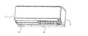
図1は、実施の形態1に係る空気調和機における室内機の分解斜視図である。
図2は、実施の形態1に係る空気調和機における室内機の断面図である。
図3は、実施の形態1に係る空気調和機における室内機の風向調整機構部分の詳細断面図である。
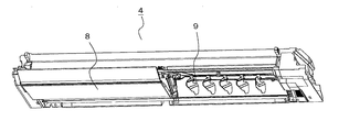
図4は、実施の形態1に係る空気調和機における室内機の風向調整機構部分の斜視図である。
図5は、実施の形態1に係る空気調和機におけるドレンパン組立体の下面斜視図である。
図6は、実施の形態1に係る空気調和機におけるドレンパン組立体の上面斜視図である。
First, a schematic structure of a wind direction adjusting mechanism for an air conditioner according to
1 is an exploded perspective view of an indoor unit in an air conditioner according to
FIG. 2 is a cross-sectional view of the indoor unit in the air conditioner according to
FIG. 3 is a detailed cross-sectional view of the wind direction adjusting mechanism portion of the indoor unit in the air conditioner according to
FIG. 4 is a perspective view of a wind direction adjusting mechanism portion of the indoor unit in the air conditioner according to
5 is a bottom perspective view of the drain pan assembly in the air conditioner according to
6 is a top perspective view of the drain pan assembly in the air conditioner according to
図1に示すように室内機は、前面筐体1と、表示パネル2と、フィルタユニット3と、ドレンパン組立体4と、熱交換器ユニット5と、送風ファンユニット6と、基台7と、により大きく構成されている。
基台7は、略箱型に形成され、空気調和機の室内機の背面側に設けられる。基台7には、室内空気と冷媒との熱交換を行う熱交換器ユニット5と、熱交換器ユニット5に室内空気を供給する送風ファンユニット6と、ドレンパンとともに吹出口の構成部材を一体化したドレンパン組立体4と、意匠部品である前面筐体1と、が取り付けられる。
As shown in FIG. 1, the indoor unit includes a
The
この室内機は、送風ファンユニット6が駆動すると、室内機上面より室内空気を吸込み、熱交換器ユニット5に室内空気を通過させることによって熱交換し冷気や暖気を生成する。そしてその冷気または暖気を吹出口を介して室内へ送風する。
When the
ドレンパン組立体4について説明する。図2、3に示すように、熱交換器ユニット5の下方には熱交換器ユニット5で発生する結露水を受けるドレンパン組立体4が配置されている。ドレンパン組立体4は、熱交換器ユニット5の結露水を受けるドレンパン部12、上下風向調整板8、左右風向調整板9、により構成されている。上下風向調整板8は吹出口の下面を覆うように室内機の左右方向に2分割されて設置されている。左右風向調整板9は、図4〜6に示すようにこの上下風向調整板8に対して室内機の内側に、室内機の左右方向に並列して複数枚配置されている。
上下風向調整板8及び左右風向調整板9は回動可能で、送風ファンユニット6により送風された空気の上下方向または左右方向の風向を調整する。
The
The up / down air
左右風向調整板9の回動機構について説明する。
図7は、実施の形態1に係る空気調和機の左右風向調整板部分の斜視図である。
図8は、実施の形態1に係る空気調和機の左右風向調整板部分の別方向からの斜視図である。
図9は、実施の形態1に係る空気調和機の左右風向調整板部分の平面図である。
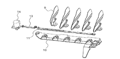
図10は、実施の形態1に係る空気調和機の左右風向調整板部分の分解斜視図である。
図11は、実施の形態1に係る空気調和機の左右風向調整板部分の拡大分解斜視図である。
A rotation mechanism of the left / right air
FIG. 7 is a perspective view of the left and right airflow direction adjusting plate portion of the air conditioner according to
FIG. 8 is a perspective view from another direction of the left and right airflow direction adjusting plate portion of the air conditioner according to
FIG. 9 is a plan view of the left and right wind direction adjusting plate portion of the air conditioner according to
FIG. 10 is an exploded perspective view of the left and right wind direction adjusting plate portion of the air conditioner according to
FIG. 11 is an enlarged exploded perspective view of the left and right airflow direction adjusting plate portion of the air conditioner according to
左右風向調整板9の回動機構は、複数の左右風向調整板9と、左右風向調整板9を支持する支持体10と、回動の動力となるモータ14と、棒形状の接続体13と、各左右風向調整板9を連結する連結棒11と、により構成される。
支持体10は、ドレンパン組立体4の一部を構成し、複数の左右風向調整板9は略等間隔の距離を隔てて支持体10に取り付けられている。
The turning mechanism of the left and right air
The
そして、複数の左右風向調整板9には、連結棒11の挿入穴11aに係合する突起部9aが形成され、挿入穴11aに対して回動自在に係合する。連結棒11は、接続体13を介してモータ14に接続され、モータ14の回転駆動を接続体13を介して左右風向調整板9に伝達することで、複数の左右風向調整板9を同時に回動させる。
左右風向調整板9、支持体10等は可とう性を有する樹脂材料(例えば、ABS、ポリプロピレン、ポリエチレン、ポリカーボネート等)で成形されている。
The plurality of left and right airflow
The left and right wind
次に、支持体10の構成について説明する。
図12は、実施の形態1に係る空気調和機における支持体の拡大斜視図である。
図12に示すように支持体10には、左右風向調整板9を取り付けるための係合凹部10aが複数形成されている。係合凹部10aは平面視において略U字状の支持面10bを底面としており、支持面10bの略中央には左右風向調整板9の回転軸となる円筒形状の軸部10cが立設されている。
Next, the configuration of the
FIG. 12 is an enlarged perspective view of a support in the air conditioner according to
As shown in FIG. 12, the
また、係合凹部10aの対向する二位置には、左右風向調整板9が軸部10cから抜け落ちるのを防止する保持部10dが形成されている。
さらに、略U字状の係合凹部10aの頂部には、切欠部10gにより断面L字形状に形成された片持ち片10eが設けられている。片持ち片10eは、断面L字形状の一端部を支持体10に接合して形成されている。そして、他端部は自由端として弾性変形できるように構成され、支持面10bと同一平面上に上面を設定された先端部10fを有している。
片持ち片10eの先端部10fの上面には、左右風向調整板9の取付方向に突出する係合突起部10hが形成されている。
Further, at two opposing positions of the
Furthermore, a
On the upper surface of the
次に、左右風向調整板9の構成について説明する。
図13は、実施の形態1に係る空気調和機における左右風向調整板の拡大斜視図である。
図14は、実施の形態1に係る空気調和機における左右風向調整板の別方向の拡大斜視図である。
図15は、実施の形態1に係る空気調和機における左右風向調整板の座部の拡大斜視図である。
Next, the configuration of the left / right airflow
FIG. 13 is an enlarged perspective view of the left and right airflow direction adjusting plate in the air conditioner according to
FIG. 14 is an enlarged perspective view of another direction of the left and right airflow direction adjusting plate in the air conditioner according to
FIG. 15 is an enlarged perspective view of the seat portion of the left and right airflow direction adjusting plate in the air conditioner according to
図13〜15に示すように風向を調整する平板状の羽根部9bと、羽根部9bが取り付けられる基部9cと、基部9cに形成され連結棒11の挿入穴11aに係合する突起部9aと、基部9cに接続され、支持体10に係合する円板形状の座部9dと、により大きく構成されている。
As shown in FIGS. 13 to 15, a
座部9dの座面9f中央には、支持体10の軸部10cが挿入される軸孔9eが開口している。また、座部9dの外周における対向する二位置には、切欠部9gが形成されている。
そして、座面9f上には、羽根部9bと平行となる位置に溝部9hが形成されている。
A
On the
このように構成された左右風向調整板9と支持体10とを係合した構成を説明する。
図16は、実施の形態1に係る空気調和機における左右風向調整板と支持体との係合部を示した斜視図である。
図17は、実施の形態1に係る空気調和機における左右風向調整板と支持体との係合部を示した断面図である。
A configuration in which the left and right wind
FIG. 16 is a perspective view showing an engagement portion between the left and right airflow direction adjusting plate and the support in the air conditioner according to
FIG. 17 is a cross-sectional view showing an engaging portion between the left and right airflow direction adjusting plate and the support in the air conditioner according to
左右風向調整板9を支持体10に取り付ける際には、左右風向調整板9の切欠部9gを支持体10の保持部10dの位置に合わせ、軸部10cを軸孔9eに挿入して座面9fが支持面10bに接面するまで押し込む。そして左右風向調整板9を回転させ、保持部10dが座部9dを抑えることで、左右風向調整板9が支持体10から外れない係合状態とする。図16は、この左右風向調整板9と支持体10との係合状態を示している。
When the left / right airflow
左右風向調整板9と支持体10との係合状態では、図17に示すように左右風向調整板9の座面9fが支持面10bに接面した状態となっている。そして、左右風向調整板9は支持体10の軸部10cを中心軸として回動自在に保持される。
In the engaged state between the left / right airflow
ここで、左右風向調整板9の向きを支持体10に対して特定の方向に固定する位置決め機構について説明する。
図16、17における左右風向調整板9と支持体10との係合状態において、左右風向調整板9が回動すると、特定の位置(例えば室内機の左右方向に対して直角の正面向き)で支持体10の係合突起部10hが左右風向調整板9の座面9fに形成された溝部9hに嵌合する。図17は、この時の状態の断面を示しており、溝部9h内に係合突起部10hが嵌合した状態となっている。
Here, a positioning mechanism that fixes the direction of the left / right airflow
When the left and right wind
この位置決め機構についてさらに説明する。
図18は、実施の形態1に係る空気調和機における左右風向調整板と支持体とが特定位置で固定されたときの断面図である。
図19は、実施の形態1に係る空気調和機における左右風向調整板と支持体とが特定位置以外で回動しているときの断面図である。
This positioning mechanism will be further described.
FIG. 18 is a cross-sectional view of the air conditioner according to
FIG. 19 is a cross-sectional view of the air conditioner according to
実施の形態1に係る支持体10の片持ち片10eは、左右風向調整板9が回動した際に、特定の位置(例えば室内機の左右方向に対して直角の正面向き)以外で図19に示すように係合突起部10hが座面9fに乗り上げる形で弾性変形する。
また、左右風向調整板9が回動して特定の位置となった時には、片持ち片10eの係合突起部10hが左右風向調整板9の座面9fに形成された溝部9hに嵌合し、図18のように片持ち片10eの弾性変形が解除される。
The
Further, when the left / right airflow
このように、左右風向調整板9の位置決め機構を特定の位置(例えば室内機の左右方向に対して直角の正面向き)で支持体10の係合突起部10hが左右風向調整板9の座面9fに形成された溝部9hに嵌合する構成とすることで、非常に簡単な構成で正確な位置決めを実現することができる。
また、左右風向調整板9が回動し、特定の位置以外となっている時には、片持ち片10eの係合突起部10hが座部9dの座面9fに乗り上げる形で片持ち片10eが弾性変形して座部9dが押さえ付けられるため、気流が羽根部9bに当たることによるびびり音を抑制する効果がある。
As described above, the
Further, when the left / right airflow
ここで、支持体10の係合突起部10hが左右風向調整板9の溝部9hに嵌合した際の断面形状について説明する。
図20は、実施の形態1に係る空気調和機における左右風向調整板の座部と支持体の片持ち片とが特定位置で係合したときの図18におけるA−A断面図である。
図21は、実施の形態1に係る空気調和機における左右風向調整板の座部と支持体の片持ち片とが特定位置で係合したときの別の例の図18におけるA−A断面図である。
図22は、実施の形態1に係る空気調和機における左右風向調整板の座部と支持体の片持ち片とが特定位置で係合したときのさらに別の例の図18におけるA−A断面図である。
Here, the cross-sectional shape when the engaging
20 is a cross-sectional view taken along line AA in FIG. 18 when the seat portion of the left and right airflow direction adjusting plate and the cantilever piece of the support body are engaged at a specific position in the air conditioner according to
FIG. 21 is a cross-sectional view taken along line AA in FIG. 18 of another example when the seat portion of the left / right airflow direction adjusting plate and the cantilever piece of the support body are engaged at a specific position in the air conditioner according to
FIG. 22 is a cross-sectional view taken along line AA in FIG. 18 of still another example when the seat portion of the left and right airflow direction adjusting plate and the cantilever piece of the support body are engaged at a specific position in the air conditioner according to
図20に示す係合突起部10hは断面が台形形状であり、溝部9hの幅寸法に対して係合突起部10hの幅の最大寸法が同一寸法に設定されている。
同様に図21に示す係合突起部10hは断面三角形状であり、溝部9hの幅寸法に対して係合突起部10hの幅の最大寸法が同一寸法に設定されている。
同様に図22に示す係合突起部10hは断面円弧形状であり、溝部9hの幅寸法に対して係合突起部10hの幅の最大寸法が同一寸法に設定されている。
また、溝部9hの深さ寸法は、係合突起部10hの高さ寸法より長く設定されている。
The
Similarly, the
Similarly, the engaging
Moreover, the depth dimension of the
図20〜22に示す断面形状による位置決め機構によれば、ずれがなく特定の位置で係合突起部10h及び溝部9hが嵌合するため、左右風向調整板9の位置を正確に固定することが可能になる。また、係合突起部10hの断面形状を台形形状、三角形状、円弧形状としたため、係合突起部10hが溝部9hを乗り越えてスムーズに固定位置から外れ、小さいモータのトルクで左右風向調整板9を駆動することが可能になる。
According to the positioning mechanism having a cross-sectional shape shown in FIGS. 20 to 22, the
さらに、支持体10の係合突起部10hが左右風向調整板9の溝部9hに嵌合した際の断面形状の別の例について説明する。
図23は、実施の形態1に係る空気調和機における左右風向調整板と支持体とが特定位置で固定されたときの別の例の断面図である。
図24は、実施の形態1に係る空気調和機における左右風向調整板の座部と支持体の片持ち片とが特定位置で係合したときの図23におけるB−B断面図である。
図25は、実施の形態1に係る空気調和機における左右風向調整板の座部と支持体の片持ち片とが特定位置で係合したときの別の例の図23におけるB−B断面図である。
図26は、実施の形態1に係る空気調和機における左右風向調整板の座部と支持体の片持ち片とが特定位置で係合したときのさらに別の例の図23におけるB−B断面図である。
Furthermore, another example of the cross-sectional shape when the engaging
FIG. 23 is a cross-sectional view of another example when the left and right wind direction adjusting plate and the support in the air conditioner according to
24 is a cross-sectional view taken along line BB in FIG. 23 when the seat portion of the left and right airflow direction adjusting plate and the cantilever piece of the support body are engaged at a specific position in the air conditioner according to
25 is a cross-sectional view taken along line BB in FIG. 23 of another example when the seat portion of the left and right airflow direction adjusting plate and the cantilever piece of the support body are engaged at a specific position in the air conditioner according to
FIG. 26 is a cross-sectional view taken along line BB in FIG. 23 of still another example when the seat portion of the left / right airflow direction adjusting plate and the cantilever piece of the support are engaged at a specific position in the air conditioner according to
図24に示す係合突起部10hは断面が台形形状であり、溝部9hの両縁に係合突起部10hの台形形状の対向する二辺が当接して嵌合する。
同様に図25に示す係合突起部10hは断面三角形状であり、溝部9hの両縁に係合突起部10hの三角形状の二辺が当接して嵌合する。
同様に図26に示す係合突起部10hは断面円弧形状であり、溝部9hの両縁に係合突起部10hの円弧形状の周縁が当接して嵌合する。
すなわち、溝部9hの幅寸法は、係合突起部10hの幅の最大寸法より短く設定されている。
The
Similarly, the engaging
Similarly, the engaging
That is, the width dimension of the
図23〜26に示す断面形状による位置決め機構によれば、係合突起部10hと溝部9hの加工精度が若干悪くても、ずれがなく特定の位置で係合突起部10h及び溝部9hが嵌合するため、左右風向調整板9の位置を正確に固定することが可能になる。また、係合突起部10hの断面形状を台形形状、三角形状、円弧形状とし、さらに、係合突起部10hの先端側のみが溝部9hに嵌合するため、係合突起部10hが溝部9hを乗り越えてスムーズに固定位置から外れ、さらに小さいモータのトルクで左右風向調整板9を駆動することが可能になる。
According to the positioning mechanism having the cross-sectional shape shown in FIGS. 23 to 26, even if the processing accuracy of the engaging
なお、実施の形態1に係る風向調整板の位置決め機構では、支持体10に係合突起部10hを設け、左右風向調整板9に溝部9hを設けた構成を説明したが、支持体10に溝部を設け、左右風向調整板9に係合突起部を設ける構成としてもよい。
In the wind direction adjusting plate positioning mechanism according to the first embodiment, the configuration in which the
このような実施の形態1に係る空気調和機の左右風向調整板9の構成によれば、風向調整板まわりの駆動機構における組み付けのばらつきがあっても、非常に簡単な構成で風向調整板を特定の方向に正確に位置決めすることを可能にし、意匠性に優れた風向調整機構、及びその風向調整機構を備えた空気調和機を得ることが可能となる。
According to the configuration of the left and right wind
実施の形態2.
実施の形態2に係る空気調和機の左右風向調整板9の向きを支持体10に対して特定の方向に固定する位置決め機構について説明する。
実施の形態2に係る位置決め機構は、実施の形態1に係る位置決め機構と支持体10の片持ち片10e及び左右風向調整板9の座部9dの構成のみが異なるため、この点を説明する。
A positioning mechanism that fixes the direction of the left and right airflow
The positioning mechanism according to the second embodiment is different from the positioning mechanism according to the first embodiment only in the configuration of the
はじめに、実施の形態2に係る支持体10の片持ち片10eの構成について説明する。
図27は、実施の形態2に係る空気調和機における支持体の拡大斜視図である。
図27に示すように支持体10には、左右風向調整板9を取り付けるための係合凹部10aが複数形成されている。係合凹部10aは平面視において略U字状の支持面10bを底面としており、支持面10bの略中央には左右風向調整板9の回転軸となる円筒形状の軸部10cが立設されている。
First, the configuration of the
FIG. 27 is an enlarged perspective view of a support in the air conditioner according to
As shown in FIG. 27, the
また、係合凹部10aの対向する二位置には、左右風向調整板9が軸部10cから抜け落ちるのを抑える保持部10dが形成されている。
さらに、略U字状の係合凹部10aの頂部には、切欠部10gにより断面L字形状に形成された片持ち片10eが設けられている。片持ち片10eは、断面L字形状の一端部を支持体10に接合して形成されている。そして、他端部は自由端として弾性変形できるように構成され、軸部10c方向に突設された平面視で略矩形形状の係合先端部10iが形成されている。
Moreover, the holding
Furthermore, a
次に、左右風向調整板9の座部9dの構成について説明する。
図28は、実施の形態2に係る空気調和機における左右風向調整板の座部の拡大斜視図である。
Next, the configuration of the
FIG. 28 is an enlarged perspective view of the seat portion of the left and right airflow direction adjusting plate in the air conditioner according to
座部9dの座面9f中央には、支持体10の軸部10cが挿入される軸孔9eが開口している。また、座部9dの外周における対向する二位置には、平面視で略矩形形状の切欠部9gが形成されている。
A
このように構成された左右風向調整板9と支持体10とを係合した構成を説明する。
左右風向調整板9を支持体10に取り付ける際には、左右風向調整板9の切欠部9gを支持体10の保持部10dの位置に合わせ、軸部10cを軸孔9eに挿入して座面9fが支持面10bに接面するまで押し込む。そして左右風向調整板9を回転させ、保持部10dが座部9dを抑えることで、左右風向調整板9が支持体10から外れない係合状態とする。左右風向調整板9と支持体10との係合状態では、左右風向調整板9の座面9fが支持面10bに接面した状態となっている。そして、左右風向調整板9は支持体10の軸部10cを中心軸として回動自在に保持される。
A configuration in which the left and right wind
When the left / right airflow
ここで、左右風向調整板9の向きを支持体10に対して特定の方向に固定する位置決め機構について説明する。
左右風向調整板9と支持体10との係合状態において、左右風向調整板9が回動すると、特定の位置(例えば室内機の左右方向に対して直角の正面向き)で支持体10の係合先端部10iが左右風向調整板9の座面9fに形成された切欠部9gに嵌合する。
係合先端部10iと切欠部9gとの円周方向の幅寸法は、略同一となっており、左右風向調整板9の位置決めの精度が確保されている。
なお、係合先端部10iと切欠部9gとの平面視の形状を略矩形形状とした例を示したが、実施の形態1と同様に係合先端部10iの形状を台形形状、三角形状、円弧形状等とすることができる。
Here, a positioning mechanism that fixes the direction of the left / right airflow
When the left and right wind
The circumferential width dimensions of the
In addition, although the example which made the shape of planar view of the engagement front-end | tip
実施の形態2に係る支持体10の片持ち片10eは、左右風向調整板9が回動した際に、特定の位置(例えば室内機の左右方向に対して直角の正面向き)以外では係合先端部10iが座部9dの外周に乗り上げる形で弾性変形する。
また、左右風向調整板9が回動して特定の位置となった時には、片持ち片10eの係合先端部10iが左右風向調整板9の座部9dに形成された切欠部9gに嵌合し、片持ち片10eの弾性変形が解除される。
The
Further, when the left / right airflow
このように、左右風向調整板9の位置決め機構を特定の位置(例えば室内機の左右方向に対して直角の正面向き)で支持体10の係合先端部10iが左右風向調整板9の座部9dに形成された切欠部9gに嵌合する構成とすることで、非常に簡単な構成で正確な位置決めを実現することができる。
また、左右風向調整板9が回動し、特定の位置以外となっている時には、片持ち片10eの係合先端部10iが座部9dの外周面に乗り上げる形で片持ち片10eが弾性変形して座部9dが押さえ付けられるため、気流が羽根部9bに当たることによるびびり音を抑制する効果がある。
As described above, the
Further, when the left / right airflow
このような実施の形態2に係る空気調和機の左右風向調整板9の構成によれば、風向調整板まわりの駆動機構における組み付けのばらつきがあっても、非常に簡単な構成で風向調整板を特定の方向に正確に位置決めすることを可能にし、意匠性に優れた風向調整機構、及びその風向調整機構を備えた空気調和機を得ることが可能となる。
According to the configuration of the left and right airflow
なお、上記実施の形態1、2では、左右風向調整板9を特定の位置として室内機の左右方向に対して直角の正面向きに固定する例を説明したが、正面向き以外の方向、例えば左右風向調整板9が最大角度回転した位置に固定することも可能である。最大角度回転した位置に固定することで、吹出口からの風圧を受けても左右風向調整板9がずれることがない。さらに、複数の固定位置を形成することも可能である。
また、実施の形態1、2では、空気調和機の室内機における風向調整板を例に説明したが、例えば加湿器や除湿機、換気装置の吹出口等、様々な気流の風向を調整する風向調整板として本発明の位置決め機構を採用することが可能である。
In the first and second embodiments, the example in which the left / right airflow
In the first and second embodiments, the wind direction adjusting plate in the indoor unit of the air conditioner has been described as an example. However, for example, a wind direction that adjusts the wind direction of various air currents such as a humidifier, a dehumidifier, and a vent of a ventilator. The positioning mechanism of the present invention can be employed as the adjustment plate.
1 前面筐体、2 表示パネル、3 フィルタユニット、4 ドレンパン組立体、5 熱交換器ユニット、6 送風ファンユニット、7 基台、8 上下風向調整板、9 左右風向調整板、9a 突起部、9b 羽根部、9c 基部、9d 座部、9e 軸孔、9f 座面、9g 切欠部、9h 溝部、10 支持体、10a 係合凹部、10b 支持面、10c 軸部、10d 保持部、10e 片持ち片、10f 先端部、10g 切欠部、10h 係合突起部、10i 係合先端部、11 連結棒、11a 挿入穴、12 ドレンパン部、13 接続体、14 モータ。
DESCRIPTION OF
Claims (9)
前記風向調整板の一端部には、前記支持体に回動可能に係合する座部が設けられ、
前記支持体には、前記座部と係合する係合凹部が形成され、前記係合凹部の側壁から前記座部の上方に向かって突き出し、前記座部を摺動可能に保持する保持部が設けられており、
前記座部と前記支持体のうち、一方には溝部が形成され、他方には前記溝部に嵌合する係合突起部が形成されており、
前記風向調整板が回動した際の特定の位置にて前記溝部と前記係合突起部とが嵌合する
ことを特徴とする風向調整機構。 A wind direction adjusting mechanism comprising a wind direction adjusting plate for adjusting the wind direction and a support body that suspends and supports the wind direction adjusting plate so as to be rotatable,
One end of the wind direction adjusting plate is provided with a seat that is rotatably engaged with the support,
The support is formed with an engaging recess that engages with the seat portion, and a holding portion that protrudes upward from the side wall of the engaging recess and holds the seat portion slidably. Provided,
Of the support and the seat portion, the groove portion is formed on one, is formed with engaging projections to be fitted before Symbol groove to the other,
The wind direction adjusting mechanism, wherein the groove and the engaging protrusion are fitted at a specific position when the wind direction adjusting plate is rotated.
前記支持体は、弾性変形が可能な片持ち片を有し、
前記座部と前記片持ち片のうち、一方には前記溝部が形成され、他方には前記係合突起部が形成されている
ことを特徴とする請求項1に記載の風向調整機構。 The seat is disc-shaped,
The support has a cantilever piece that can be elastically deformed;
Among the cantilever and the seat, whereas the groove is formed on, the other hand the wind direction adjustment mechanism according to claim 1, wherein the Ru Tei is formed the engaging projection portions.
該座面には前記溝部が形成され、
前記片持ち片には前記係合突起部が形成される
ことを特徴とする請求項2に記載の風向調整機構。 The seat portion of the wind direction adjusting plate has a circular seat surface,
The groove is formed on the seating surface,
The wind direction adjusting mechanism according to claim 2, wherein the engagement protrusion is formed on the cantilever piece.
前記片持ち片には前記係合突起部が形成される
ことを特徴とする請求項2に記載の風向調整機構。 The groove is formed on the outer periphery of the seat,
The wind direction adjusting mechanism according to claim 2, wherein the engagement protrusion is formed on the cantilever piece.
前記溝部の深さ寸法は、前記係合突起部の高さ寸法より長く構成された
ことを特徴とする請求項1〜4のいずれか1項に記載の風向調整機構。 The width of the groove is the same as the maximum width of the engaging protrusion,
The depth direction of the said groove part was comprised longer than the height dimension of the said engagement protrusion part. The wind direction adjustment mechanism of any one of Claims 1-4 characterized by the above-mentioned.
ことを特徴とする請求項1〜4のいずれか1項に記載の風向調整機構。 The wind direction adjusting mechanism according to any one of claims 1 to 4, wherein a width dimension of the groove part is configured to be shorter than a maximum dimension of the width of the engaging protrusion part.
ことを特徴とする請求項1〜6のいずれか1項に記載の風向調整機構。 7. The wind direction adjusting mechanism according to claim 1, wherein a cross-sectional shape of the engagement protrusion in a longitudinal direction is any one of a trapezoidal shape, a triangular shape, and an arc shape.
前記特定の位置は、前記風向調整板が前記空気調和機の左右方向に直交する正面向きとなる位置であることを特徴とする空気調和機。 An air conditioner comprising the wind direction adjusting mechanism according to any one of claims 1 to 8,
The said specific position is a position where the said wind direction adjustment board turns into the front direction orthogonal to the left-right direction of the said air conditioner, The air conditioner characterized by the above-mentioned.
Priority Applications (2)
| Application Number | Priority Date | Filing Date | Title |
|---|---|---|---|
| JP2014145801A JP6274994B2 (en) | 2014-07-16 | 2014-07-16 | Wind direction adjusting mechanism and air conditioner equipped with the wind direction adjusting mechanism |
| CN201520224097.4U CN204612106U (en) | 2014-07-16 | 2015-04-14 | Wind direction regulating mechanism and possess the air conditioner of this Wind direction regulating mechanism |
Applications Claiming Priority (1)
| Application Number | Priority Date | Filing Date | Title |
|---|---|---|---|
| JP2014145801A JP6274994B2 (en) | 2014-07-16 | 2014-07-16 | Wind direction adjusting mechanism and air conditioner equipped with the wind direction adjusting mechanism |
Publications (3)
| Publication Number | Publication Date |
|---|---|
| JP2016023813A JP2016023813A (en) | 2016-02-08 |
| JP2016023813A5 JP2016023813A5 (en) | 2016-07-21 |
| JP6274994B2 true JP6274994B2 (en) | 2018-02-07 |
Family
ID=53964661
Family Applications (1)
| Application Number | Title | Priority Date | Filing Date |
|---|---|---|---|
| JP2014145801A Expired - Fee Related JP6274994B2 (en) | 2014-07-16 | 2014-07-16 | Wind direction adjusting mechanism and air conditioner equipped with the wind direction adjusting mechanism |
Country Status (2)
| Country | Link |
|---|---|
| JP (1) | JP6274994B2 (en) |
| CN (1) | CN204612106U (en) |
Families Citing this family (3)
| Publication number | Priority date | Publication date | Assignee | Title |
|---|---|---|---|---|
| WO2019008666A1 (en) * | 2017-07-04 | 2019-01-10 | 三菱電機株式会社 | Air flow modification device for air conditioners, indoor unit comprising same air flow modification device, and air conditioner comprising same indoor unit |
| CN210089093U (en) * | 2017-11-13 | 2020-02-18 | 三菱电机株式会社 | Indoor unit and air conditioner |
| CN111989526B (en) * | 2018-04-24 | 2021-11-02 | 三菱电机株式会社 | Wind direction adjustment mechanism, indoor unit of air conditioner, and air conditioner |
Family Cites Families (9)
| Publication number | Priority date | Publication date | Assignee | Title |
|---|---|---|---|---|
| JPS5329015Y2 (en) * | 1973-10-16 | 1978-07-20 | ||
| JPH08313044A (en) * | 1995-05-20 | 1996-11-29 | Mitsubishi Heavy Ind Ltd | Air-direction adjusting device for air conditioner |
| JP2000088336A (en) * | 1998-09-14 | 2000-03-31 | Sharp Corp | Blower |
| JP4654661B2 (en) * | 2004-11-02 | 2011-03-23 | ダイキン工業株式会社 | Wind direction adjusting mechanism and air conditioner having the same |
| JP2009058206A (en) * | 2007-09-03 | 2009-03-19 | Toshiba Carrier Corp | Air-conditioner indoor unit |
| CA2701426A1 (en) * | 2007-10-03 | 2009-04-09 | Verne Mutton | Improved airflow regulator |
| JP5392273B2 (en) * | 2011-01-17 | 2014-01-22 | ダイキン工業株式会社 | Indoor unit |
| JP5796313B2 (en) * | 2011-03-17 | 2015-10-21 | 株式会社富士通ゼネラル | Wind direction changing device and air conditioner equipped with the same |
| JP2013096684A (en) * | 2011-11-07 | 2013-05-20 | Hitachi Appliances Inc | Deflector mounting structure of air conditioner |
-
2014
- 2014-07-16 JP JP2014145801A patent/JP6274994B2/en not_active Expired - Fee Related
-
2015
- 2015-04-14 CN CN201520224097.4U patent/CN204612106U/en not_active Expired - Fee Related
Also Published As
| Publication number | Publication date |
|---|---|
| CN204612106U (en) | 2015-09-02 |
| JP2016023813A (en) | 2016-02-08 |
Similar Documents
| Publication | Publication Date | Title |
|---|---|---|
| JP4624174B2 (en) | Air conditioner | |
| JP6274994B2 (en) | Wind direction adjusting mechanism and air conditioner equipped with the wind direction adjusting mechanism | |
| US20180073755A9 (en) | Indoor device for air conditioner having wind visors | |
| KR20160017587A (en) | Air conditioner | |
| JP2009058145A (en) | Air conditioner | |
| JP2015218996A (en) | Wind direction adjustment device for air conditioner and air conditioner | |
| JP2002071206A (en) | Attaching/detaching device for vertical wind direction adjusting plate | |
| JP4703336B2 (en) | Air conditioner | |
| JP4610412B2 (en) | Air conditioner | |
| JP6207479B2 (en) | Indoor unit for air conditioner and method for manufacturing indoor unit for air conditioner | |
| JP4654661B2 (en) | Wind direction adjusting mechanism and air conditioner having the same | |
| JP4675752B2 (en) | Air conditioner | |
| JP4675085B2 (en) | Air conditioner | |
| CN112648212A (en) | Fan structure and fan | |
| JP4419153B2 (en) | Hair dryer | |
| JPWO2016098222A1 (en) | Temperature detector and air conditioner indoor unit | |
| JP2011089698A (en) | Air conditioner | |
| KR20200081113A (en) | Assembly structure of indoor unit | |
| JP5980168B2 (en) | Air conditioner indoor unit | |
| JP4463147B2 (en) | Air conditioner | |
| CN214304474U (en) | Fan structure and fan | |
| JP6200547B2 (en) | Wind direction changing device and air conditioner having the same | |
| WO2019030814A1 (en) | Air conditioner indoor unit | |
| JP6161372B2 (en) | Damper device | |
| CN210089093U (en) | Indoor unit and air conditioner |
Legal Events
| Date | Code | Title | Description |
|---|---|---|---|
| A521 | Written amendment |
Free format text: JAPANESE INTERMEDIATE CODE: A523 Effective date: 20160603 |
|
| A621 | Written request for application examination |
Free format text: JAPANESE INTERMEDIATE CODE: A621 Effective date: 20160603 |
|
| A977 | Report on retrieval |
Free format text: JAPANESE INTERMEDIATE CODE: A971007 Effective date: 20170303 |
|
| A131 | Notification of reasons for refusal |
Free format text: JAPANESE INTERMEDIATE CODE: A131 Effective date: 20170509 |
|
| A521 | Written amendment |
Free format text: JAPANESE INTERMEDIATE CODE: A523 Effective date: 20170705 |
|
| TRDD | Decision of grant or rejection written | ||
| A01 | Written decision to grant a patent or to grant a registration (utility model) |
Free format text: JAPANESE INTERMEDIATE CODE: A01 Effective date: 20171212 |
|
| A61 | First payment of annual fees (during grant procedure) |
Free format text: JAPANESE INTERMEDIATE CODE: A61 Effective date: 20180109 |
|
| R150 | Certificate of patent or registration of utility model |
Ref document number: 6274994 Country of ref document: JP Free format text: JAPANESE INTERMEDIATE CODE: R150 |
|
| LAPS | Cancellation because of no payment of annual fees |