RU2516603C1 - Road structure - Google Patents
Road structure Download PDFInfo
- Publication number
- RU2516603C1 RU2516603C1 RU2012142477/03A RU2012142477A RU2516603C1 RU 2516603 C1 RU2516603 C1 RU 2516603C1 RU 2012142477/03 A RU2012142477/03 A RU 2012142477/03A RU 2012142477 A RU2012142477 A RU 2012142477A RU 2516603 C1 RU2516603 C1 RU 2516603C1
- Authority
- RU
- Russia
- Prior art keywords
- road
- subgrade
- base
- road structure
- drainage
- Prior art date
Links
Images


Abstract
Description
Описание изобретенияDescription of the invention
Изобретение относится к области строительства и широко может быть использовано при возведении земляного полотна автомобильных и железных дорог, взлетно-посадочных полос аэродромов, использовано в районах, характеризующихся глубоким сезонным промерзанием грунтов и высоким уровнем грунтовых вод.The invention relates to the field of construction and can be widely used in the construction of the roadbed of railways and railways, runways of airfields, used in areas characterized by deep seasonal freezing of soils and a high level of groundwater.
Известна конструкция земляного полотна, включающая для ее устройства применение зернистых материалов: щебеночные, песчано-гравийные смеси, шлаки и непучинистые грунты (Инструкция по проектированию дорожных одежд нежесткого типа, М.: Транспорт, 1985 г., с.12).The construction of the subgrade is known, including the use of granular materials for its device: crushed stone, sand-gravel mixtures, slag and non-porous soils (Instructions for the design of non-rigid road pavement, M .: Transport, 1985, p.12).
Для возведения земляного полотна применяется послойное распределение и уплотнение грунта по всему поперечному сечению.For the construction of the subgrade, layer-by-layer distribution and compaction of the soil over the entire cross section are used.
Уплотнение грунта должно быть близким к пределу прочности грунта. При недостаточных контактных давлениях необходимая плотность не может быть достигнута, а при превышении давлений возникают явления разуплотнения: волнообразование, выдавливание грунта в стороны (Гремышев Н.В., Технология и организация строительства автомобильных дорог. М.: Транспорт, 1992 г., с.36).Soil compaction should be close to the ultimate strength of the soil. With insufficient contact pressures, the required density cannot be achieved, and when pressures are exceeded, decompression phenomena occur: wave formation, extrusion of soil to the sides (Gremyshev N.V., Technology and organization of road construction. M .: Transport, 1992, p. 36).
Известно также основание дорожного и аэродромного покрытия, включающее уплотненный грунт, размещенный в оболочке из грунта, укрепленного вяжущими материалами (а.с. №601343, E01C 3/04).The base of the road and airfield pavement is also known, including compacted soil placed in a shell made of soil reinforced with cementitious materials (AS No. 601343, E01C 3/04).
Наиболее близким к изобретению является дорожная конструкция, включающая дорожную одежду, дренирующий слой, земляное полотно, верхняя часть которого заключена в гидроизоляционную обойму (патент RU №2035536, E01C 3/06).Closest to the invention is a road structure including pavement, a drainage layer, a subgrade, the upper part of which is enclosed in a waterproofing clip (patent RU No. 2035536, E01C 3/06).
Недостатком этого основания является то, что устройство его трудоемкое, включает в себя применение дорогостоящих материалов, сложную технологию строительства, а также выполнено без учета образования уплотненного жесткого ядра под покрытием дороги (Цитович Н.А. Механика грунтов. М.: Высшая школа, 1979 г., с.109-130). Следовательно, такое дорожное основание земляного полотна находится в фазе дальнейшего уплотнения и не отвечает максимальной несущей способности грунтов, допускает значительные просадки при эксплуатации, образование келейности.The disadvantage of this foundation is that its device is time-consuming, includes the use of expensive materials, complex construction technology, and is also performed without taking into account the formation of a compacted hard core under the road surface (N. Tsitovich, Soil Mechanics. M.: Higher School, 1979 city, pp. 109-130). Therefore, such a road foundation of the subgrade is in the phase of further compaction and does not meet the maximum bearing capacity of soils, allows significant drawdowns during operation, the formation of cells.
Целью изобретения является достижение максимальной несущей способности земляного полотна, уменьшение его просадки при эксплуатации и образования колейности, создание оптимального водно-теплового режима земляного полотна и дорожной одежды.The aim of the invention is to achieve maximum bearing capacity of the subgrade, reducing its subsidence during operation and the formation of ruts, creating the optimal water-thermal regime of the subgrade and pavement.
Поставленная цель достигается путем возведения земляного полотна с устройством уплотненного жесткого ядра треугольной формы под каждую колею дорожного покрытия (ширина колеи определяется нормативной нагрузкой АК от автотранспортных средств на автомобильных дорогах общего пользования ГОСТ Р 52748-2007) из прочных легкоуплотняемых зернистых материалов, а также щебеночных, песчано-гравийных смесей, шлаков и непучинистых грунтов, обладающих дренирующими свойствами, с учетом φ-угла внутреннего трения грунта основания насыпи и С - сцепления грунта основания насыпи. В зависимости от геологических условий и применяемых грунтов в основание насыпи, жесткое ядро может устраиваться на подстилающем геотекстильном материале или гидроизолирующем слое из полиэтиленовой пленки. Геотекстильный материал или полиэтиленовая пленка, уложенные из рулонов внахлест на 30-40 см в поперечном сечении, сшиваются, либо склеиваются, либо свариваются и служат для обеспечения отвода воды из основания дорожного полотна в предусмотренную продольную дренажную систему с поперечным отводом в район водостоков, а также для перераспределения передаточной нагрузки от уплотненного ядра на земляное основание дороги.This goal is achieved by erecting a subgrade with a compacted hard core of a triangular shape for each track of the pavement (the track width is determined by the standard load of AK from vehicles on public roads GOST R 52748-2007) from durable easily compacted granular materials, as well as crushed stone, sand and gravel mixtures, slag and non-porous soils with drainage properties, taking into account the φ-angle of internal friction of the soil of the base of the embankment and C - adhesion g Unt mound base. Depending on the geological conditions and the primers used in the base of the embankment, a rigid core can be arranged on the underlying geotextile material or a waterproofing layer of plastic film. A geotextile material or a polyethylene film, laid out from rolls with an overlap of 30-40 cm in cross section, are sewn, either glued or welded and serve to ensure the drainage of water from the base of the roadway to the provided longitudinal drainage system with a lateral drainage to the gutter area, as well as to redistribute the transfer load from the compacted core to the ground foundation of the road.
Сущность предлагаемого изобретения заключается в следующем: при устройстве конструкции дорожного основания, где верхний слой грунта является более хорошим (малосжимаемым), то есть E1 - модуль деформации грунта верхнего слоя больше E2 - модуля деформации грунта нижнего слоя, то эпюра δ под центром тяжести дорожного покрытия будет с глубиной затухать быстрее (осадка минимальна). И наоборот, если верхний слой грунта является более слабым (с малым значением модуля деформации), то эпюра δ под центром тяжести дорожного покрытия будет с глубиной затухать медленнее, а, следовательно, и осадка на таком грунте будет больше. Таким образом, возведение земляного полотна с устройством под каждой колеей проезжей части дорожного покрытия жесткого ядра треугольной формы из прочных материалов, в зоне наибольших напряжений, обеспечит его минимальную просадку. При этом уплотненные жесткие ядра треугольной формы устроены глубиной заложения с учетом толщины расклинцованной щебеночной подушки конструкции покрытия. Глубина (Н) заложения устраиваемого жесткого ядра в основание насыпи земляного полотна определяется расчетной колеей проезжей части, φ - углом внутреннего трения грунта и С - сцеплением грунта. Чем больше С - сцепление грунта, тем меньше глубина (H2) заложения жесткого ядра (Фиг.1, Фиг.2).The essence of the invention consists in the following: when constructing a road base, where the topsoil is better (low compressible), that is, E 1 is the modulus of deformation of the soil of the upper layer is greater than E 2 is the modulus of deformation of the soil of the lower layer, then the diagram δ under the center of gravity the road surface will fade faster with depth (settlement is minimal). Conversely, if the topsoil is weaker (with a small value of the deformation modulus), then the plot δ under the center of gravity of the pavement will decay slower with depth, and, consequently, the sediment on such soil will be more. Thus, the construction of a subgrade with a device under each track of the roadway of the paving of a rigid triangular-shaped core made of durable materials in the zone of greatest stresses will ensure its minimal drawdown. At the same time, compacted rigid triangular-shaped cores are arranged with a depth of laying taking into account the thickness of the expanded clay crushed stone cushion of the coating structure. The depth (N) of laying the arranged hard core at the base of the embankment of the subgrade is determined by the estimated track of the roadway, φ is the angle of internal friction of the soil and C is the adhesion of the soil. The more C is the adhesion of the soil, the less is the depth (H 2 ) of the hard core (Figure 1, Figure 2).
Предлагаемую дорожную конструкцию устраивают в насыпи следующим образом. Сначала снимают верхний растительный слой с уплотнением грунта, затем методом послойного распределения и уплотнения грунта по всему поперечному сечению укладывают основание 1 из местного грунта близрасположенных кюветов или резервов. Затем устраивается корыто под щебеночную подушку дорожного покрытия с последовательным устройством продольных траншей для устройства жесткого ядра 2 землеройными траншеекопателями (Домбровский Н.Г. Многоковшовые экскаваторы - конструкция, теория, расчет, 1972 г.). В клине уплотненного жесткого ядра устраивается продольный дренаж 3 с поперечными дренажными отводами 4 и водоотводными лотками насыпи 5 в районе водосборников. Дренаж устраивается закрытого типа и отличается тем, что к дренирующему слою, выполненному в виде наброски из крупного щебня фракции 20-40 или гравия с отводящими трубами, перекрыт доступ поверхностных вод за счет слоев дорожного покрытия. Трубы для дренажа могут применяться гончарные, керамические, бетонные, пластмассовые и другие. Диаметр труб 0,15-0,20 м. При этом поперечные дренажные отводы 4 устраиваются с уклоном не менее 2%, что обеспечивает сток воды из дренажной системы земляного полотна. Методом «от себя» производится засыпка траншеи жесткого ядра прочным легкоуплотняемым зернистым материалом, щебнем, песчано-гравийной смесью, шлаком или непучинистыми грунтами, обладающими дренирующими свойствами, и аналогичным способом устраивают следующую траншею. Затем устраивается щебеночная подушка проезжей части 6 и двухслойное асфальтобетонное покрытие 7. В зависимости от геологических условий и применяемых грунтов в основание насыпи, жесткое ядро может устраиваться на подстилающем геотекстильном материале или гидроизолирующем слое из полиэтиленовой пленки 8 (Фиг.3).The proposed road structure is arranged in the embankment as follows. First, remove the upper vegetative layer with soil compaction, then lay the
Работает такая дорожная конструкция следующим образом: в зоне, непосредственно под каждой колеей проезжей части дороги, образован клин треугольного жесткого ядра из уплотненного грунта и объединен со щебеночной подушкой асфальтобетонного покрытия.Such a road structure works as follows: in the area, directly under each track of the carriageway, a wedge of a triangular hard core is formed from compacted soil and combined with a crushed stone cushion of asphalt concrete pavement.
Такое тело конструкции основания асфальтобетонного покрытия приобретает свойства ортотропности, так как через каждую точку проходят три взаимно перпендикулярные плоскости упругой симметрии. Направив оси координат перпендикулярно плоскостям симметрии, получим:Such a body of the base structure of the asphalt concrete coating acquires orthotropic properties, since three mutually perpendicular planes of elastic symmetry pass through each point. Having directed the coordinate axes perpendicular to the planes of symmetry, we obtain:

При этом a ij=a ji.Moreover, a ij = a ji .
Выражая упругие постоянные через так называемые технические постоянные, можно соотношениям (1) придать иной вид:Expressing the elastic constants through the so-called technical constants, we can give the relations (1) a different form:
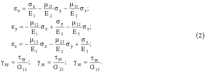
Здесь E1, E2, E3 - модули продольной упругости; G12, G23, G13 - модули сдвига; µ12, µ21, µ13, µ31, µ23, µ32 - коэффициенты Пуассона.Here E 1 , E 2 , E 3 are the moduli of longitudinal elasticity; G 12 , G 23 , G 13 - shear moduli; µ 12 , µ 21 , µ 13 , µ 31 , µ 23 , µ 32 - Poisson's ratios.
При этом E1µ21=E2µ12; E2µ32=E3µ23; E3µ13=E1µ31.Moreover, E 1 µ 21 = E 2 µ 12 ; E 2 µ 32 = E 3 µ 23 ; E 3 µ 13 = E 1 µ 31 .
Предложенная конструкция основания земляного полотна дороги обладает наибольшей несущей способностью, работает как единое целое, и давление от нее передается на боковые стороны насыпи.The proposed construction of the base of the roadbed has the greatest bearing capacity, works as a whole, and the pressure from it is transmitted to the sides of the embankment.
Такое выполнение дорожной конструкции позволяет производить отвод воды из основания земляного полотна через дренажную систему в водостоки, что исключает возникновение пучин.This embodiment of the road structure allows water to be drained from the base of the subgrade through the drainage system to drains, which eliminates the occurrence of abysses.
В предложенной конструкции удается повысить прочность основания земляного полотна, уменьшить просадки при эксплуатации.In the proposed design, it is possible to increase the strength of the base of the subgrade, to reduce drawdowns during operation.
Высокие прочность и морозоустойчивость предлагаемой дорожной конструкции объясняется тем, что влага, попавшая в процессе строительства или эксплуатации в зону треугольного жесткого ядра, будет отведена в дренажную систему, а из обочины откосов насыпи - естественным путем. Поэтому влажность грунта в течение всего периода службы дорожной конструкции не будет превышать оптимального значения.The high strength and frost resistance of the proposed road structure is explained by the fact that moisture that has got into the area of a triangular hard core during construction or operation will be diverted to the drainage system, and naturally from the side of the slope of the embankment. Therefore, the moisture content of the soil during the entire period of service of the road structure will not exceed the optimal value.
Применение предлагаемой дорожной конструкции позволяет:The application of the proposed road structure allows you to:
восстановить высокие транспортно-эксплуатационные характеристики автомобильных дорог на длительный период времени;restore high transport and operational characteristics of roads for a long period of time;
снизить последующие эксплуатационные затраты;reduce subsequent operating costs;
увеличить несущую способность (модуля упругости) дорожной одежды, что обеспечивает пропуск автомобильного транспорта с большими нагрузками на ось, и исключить закрытие дорог в зимне-весенний период.to increase the bearing capacity (elastic modulus) of the pavement, which ensures the passage of vehicles with high axle loads, and to exclude the closure of roads in the winter-spring period.
Предлагаемая дорожная конструкция рекомендуется для автомобильных и железных дорог, взлетно-посадочных полос аэродромов, а также для районов, характеризующихся глубоким сезонным уровнем грунтовых вод.The proposed road structure is recommended for roads and railways, runways of airfields, as well as for areas characterized by a deep seasonal groundwater level.
Claims (4)
Priority Applications (1)
| Application Number | Priority Date | Filing Date | Title |
|---|---|---|---|
| RU2012142477/03A RU2516603C1 (en) | 2012-10-04 | 2012-10-04 | Road structure |
Applications Claiming Priority (1)
| Application Number | Priority Date | Filing Date | Title |
|---|---|---|---|
| RU2012142477/03A RU2516603C1 (en) | 2012-10-04 | 2012-10-04 | Road structure |
Publications (2)
| Publication Number | Publication Date |
|---|---|
| RU2012142477A RU2012142477A (en) | 2014-04-10 |
| RU2516603C1 true RU2516603C1 (en) | 2014-05-20 |
Family
ID=50435973
Family Applications (1)
| Application Number | Title | Priority Date | Filing Date |
|---|---|---|---|
| RU2012142477/03A RU2516603C1 (en) | 2012-10-04 | 2012-10-04 | Road structure |
Country Status (1)
| Country | Link |
|---|---|
| RU (1) | RU2516603C1 (en) |
Cited By (3)
| Publication number | Priority date | Publication date | Assignee | Title |
|---|---|---|---|---|
| RU2573892C1 (en) * | 2014-12-01 | 2016-01-27 | Петр Никифорович Лищук | Road structure |
| CN105625129A (en) * | 2016-01-17 | 2016-06-01 | 游洪臣 | Constructing method of rice field roadbed |
| RU218662U1 (en) * | 2022-12-28 | 2023-06-05 | Тенгиз Евгеньевич Кобидзе | TRAY PART OF UNDERGROUND AND INTERESTED STRUCTURES CONSTRUCTED BY THE OPEN METHOD |
Citations (6)
| Publication number | Priority date | Publication date | Assignee | Title |
|---|---|---|---|---|
| SU1268669A1 (en) * | 1984-08-09 | 1986-11-07 | Институт Геотехнической Механики Ан Усср | Earth-fill structure |
| EP0235853B1 (en) * | 1986-02-21 | 1990-07-04 | Akzo N.V. | Supporting fabric for bearing bulk material and a method of building a road embankment, a dam, a concrete structure or some other body formed of bulk material |
| RU2035536C1 (en) * | 1992-11-02 | 1995-05-20 | Архангельский лесотехнический институт им.В.В.Куйбышева | Road structure |
| RU2233934C1 (en) * | 2002-12-25 | 2004-08-10 | Хабаровский государственный технический университет | Motor road |
| JP2005163448A (en) * | 2003-12-04 | 2005-06-23 | Taisei Corp | Mound structure having final disposal site in parallel therewith |
| RU2368719C1 (en) * | 2008-05-12 | 2009-09-27 | Государственное образовательное учреждение высшего профессионального образования "Брянская государственная инженерно-технологическая академия" | Road structure |
-
2012
- 2012-10-04 RU RU2012142477/03A patent/RU2516603C1/en not_active IP Right Cessation
Patent Citations (6)
| Publication number | Priority date | Publication date | Assignee | Title |
|---|---|---|---|---|
| SU1268669A1 (en) * | 1984-08-09 | 1986-11-07 | Институт Геотехнической Механики Ан Усср | Earth-fill structure |
| EP0235853B1 (en) * | 1986-02-21 | 1990-07-04 | Akzo N.V. | Supporting fabric for bearing bulk material and a method of building a road embankment, a dam, a concrete structure or some other body formed of bulk material |
| RU2035536C1 (en) * | 1992-11-02 | 1995-05-20 | Архангельский лесотехнический институт им.В.В.Куйбышева | Road structure |
| RU2233934C1 (en) * | 2002-12-25 | 2004-08-10 | Хабаровский государственный технический университет | Motor road |
| JP2005163448A (en) * | 2003-12-04 | 2005-06-23 | Taisei Corp | Mound structure having final disposal site in parallel therewith |
| RU2368719C1 (en) * | 2008-05-12 | 2009-09-27 | Государственное образовательное учреждение высшего профессионального образования "Брянская государственная инженерно-технологическая академия" | Road structure |
Cited By (3)
| Publication number | Priority date | Publication date | Assignee | Title |
|---|---|---|---|---|
| RU2573892C1 (en) * | 2014-12-01 | 2016-01-27 | Петр Никифорович Лищук | Road structure |
| CN105625129A (en) * | 2016-01-17 | 2016-06-01 | 游洪臣 | Constructing method of rice field roadbed |
| RU218662U1 (en) * | 2022-12-28 | 2023-06-05 | Тенгиз Евгеньевич Кобидзе | TRAY PART OF UNDERGROUND AND INTERESTED STRUCTURES CONSTRUCTED BY THE OPEN METHOD |
Also Published As
| Publication number | Publication date |
|---|---|
| RU2012142477A (en) | 2014-04-10 |
Similar Documents
| Publication | Publication Date | Title |
|---|---|---|
| CN101603286B (en) | Asphalt stabilized macadam overlay reforming method for old road and structure thereof | |
| Keller | Application of geosynthetics on low-volume roads | |
| CN106192646A (en) | Vcehicular tunnel car-driving shock-absorbing denoising structure and construction method thereof | |
| CN204212018U (en) | A kind of road structure preventing and treating the soft soil roadbed freeze thawing disease of high and cold mountain area cheuch section | |
| Zumrawi | The impacts of poor drainage on road performance in Khartoum | |
| JP5815360B2 (en) | Improved ground and its construction method | |
| CN203498721U (en) | Three-dimensional drainage roadbed structure preventing damage by water of road in cold region | |
| RU2573892C1 (en) | Road structure | |
| RU2312181C1 (en) | Road structure | |
| Hashim et al. | An experimental comparison between different types of surface patterns of permeable interlocking concrete pavement for roadway subsurface drainage | |
| CN110670436A (en) | Structure for preventing urban road subgrade from non-uniform settlement and construction method thereof | |
| CN109505213A (en) | A kind of the seif-citing rate reinforced concrete pavement structure and its construction method of both sides draining | |
| RU2516408C1 (en) | Road structure | |
| RU2516603C1 (en) | Road structure | |
| RU170257U1 (en) | The device for waterproofing the dividing strip of road pavement on a subsiding ground | |
| CN107268373A (en) | A kind of water permeability asphalt concrete road and its construction method | |
| Emersleben et al. | The use of recycled glass for the construction of pavements | |
| US20120269573A1 (en) | Systems and Methods for Diverting Sub-surface Water | |
| CN206127789U (en) | Structure of making an uproar falls in highway tunnel driving damping | |
| Ali | Manual RC box culvert analysis and designing | |
| CN212895755U (en) | Urban road sidewalk drainage device | |
| CN113152628A (en) | V-shaped gully high-fill temporary drainage system and construction method thereof | |
| EP3480360B1 (en) | Road surface comprising one or more porous strips | |
| CN209873485U (en) | Permanent temporary combined toilet structure for gully treatment | |
| CN112195701A (en) | Soft soil foundation structure and construction method thereof |
Legal Events
| Date | Code | Title | Description |
|---|---|---|---|
| MM4A | The patent is invalid due to non-payment of fees |
Effective date: 20171005 |