RU2503584C2 - Maneuvering aircraft - Google Patents
Maneuvering aircraft Download PDFInfo
- Publication number
- RU2503584C2 RU2503584C2 RU2011154439/11A RU2011154439A RU2503584C2 RU 2503584 C2 RU2503584 C2 RU 2503584C2 RU 2011154439/11 A RU2011154439/11 A RU 2011154439/11A RU 2011154439 A RU2011154439 A RU 2011154439A RU 2503584 C2 RU2503584 C2 RU 2503584C2
- Authority
- RU
- Russia
- Prior art keywords
- aircraft
- wing
- fuselage
- attack
- angles
- Prior art date
Links
- 239000000126 substance Substances 0.000 abstract 1
- 230000009189 diving Effects 0.000 description 5
- 230000004941 influx Effects 0.000 description 5
- 230000003068 static effect Effects 0.000 description 3
- 239000000725 suspension Substances 0.000 description 1
Images
Classifications
-
- B—PERFORMING OPERATIONS; TRANSPORTING
- B64—AIRCRAFT; AVIATION; COSMONAUTICS
- B64C—AEROPLANES; HELICOPTERS
- B64C3/00—Wings
- B64C3/10—Shape of wings
-
- B—PERFORMING OPERATIONS; TRANSPORTING
- B64—AIRCRAFT; AVIATION; COSMONAUTICS
- B64C—AEROPLANES; HELICOPTERS
- B64C9/00—Adjustable control surfaces or members, e.g. rudders
- B64C9/14—Adjustable control surfaces or members, e.g. rudders forming slots
- B64C9/22—Adjustable control surfaces or members, e.g. rudders forming slots at the front of the wing
- B64C9/24—Adjustable control surfaces or members, e.g. rudders forming slots at the front of the wing by single flap
-
- Y—GENERAL TAGGING OF NEW TECHNOLOGICAL DEVELOPMENTS; GENERAL TAGGING OF CROSS-SECTIONAL TECHNOLOGIES SPANNING OVER SEVERAL SECTIONS OF THE IPC; TECHNICAL SUBJECTS COVERED BY FORMER USPC CROSS-REFERENCE ART COLLECTIONS [XRACs] AND DIGESTS
- Y02—TECHNOLOGIES OR APPLICATIONS FOR MITIGATION OR ADAPTATION AGAINST CLIMATE CHANGE
- Y02T—CLIMATE CHANGE MITIGATION TECHNOLOGIES RELATED TO TRANSPORTATION
- Y02T50/00—Aeronautics or air transport
- Y02T50/10—Drag reduction
Landscapes
- Engineering & Computer Science (AREA)
- Aviation & Aerospace Engineering (AREA)
- Mechanical Engineering (AREA)
- Toys (AREA)
- Tires In General (AREA)
Abstract
Description
Изобретение относится к авиации, а именно к маневренным самолетам и системам их управления самолета.The invention relates to aviation, namely to maneuverable aircraft and their aircraft control systems.
Известен маневренный самолет, содержащий фюзеляж, стреловидное крыло умеренной стреловидности, передние наплывы большой стреловидности, органы управления, шасси (RU, 2302975 С2).Known maneuverable aircraft containing the fuselage, the swept wing of moderate sweep, the front influx of large sweep, controls, landing gear (RU, 2302975 C2).
Известный самолет обладает высокими несущими свойствами на дозвуковых и сверхзвуковых режимах. На сверхзвуковых скоростях передние наплывы существенно сдвигают фокус самолета вперед, тем самым обеспечивая уменьшение запаса статической устойчивости самолета, что, в свою очередь, уменьшает потери аэродинамического качества на балансировку, увеличивает маневренные возможности самолета.A well-known aircraft has high load-bearing properties in subsonic and supersonic modes. At supersonic speeds, the frontal influences significantly shift the focus of the aircraft forward, thereby ensuring a decrease in the static stability margin of the aircraft, which, in turn, reduces the loss of aerodynamic quality for balancing, increases the maneuverability of the aircraft.
В качестве недостатков известного самолета следует указать следующее. На закритических углах атаки, когда на концевых частях крыла происходит срыв потока, передние наплывы продолжают создавать подъемную силу, создавая момент на кабрирование, что в результате приводит к уменьшению располагаемого момента на пикирование, а для самолета с полным комплектом грузов на внешних подвесках даже к его отсутствию (на предельно-задних центровках).The disadvantages of the known aircraft should indicate the following. At supercritical angles of attack, when flow stalls at the end parts of the wing, the frontal influxes continue to create lift, creating a moment for curbing, which leads to a decrease in the available dive moment, and even for an airplane with a full set of loads on external suspensions absence (at the extreme rear centers).
Технический результат, на достижение которого направлено изобретение, заключается в повышении безопасности полетов и боевой эффективности самолета путем увеличения запасов пикирующего момента и соответственно расширения диапазона допустимых центровок и увеличения средств боевого оснащения самолета, а также реализации наилучшего соотношения подъемной силы и сопротивления.The technical result to which the invention is directed is to increase flight safety and combat effectiveness of the aircraft by increasing the stock of diving moment and, accordingly, expanding the range of permissible alignments and increasing the means of combat equipment of the aircraft, as well as realizing the best ratio of lift and drag.
Указанный технический результат достигается тем, что в маневренном самолете, содержащем фюзеляж, стреловидное крыло, передние стреловидные наплывы, органы управления, шасси, передние наплывы расположены в зоне сочленения головной и средней частей фюзеляжа и снабжены управляемыми поворотными поверхностями, при этом оси поворота управляемых поверхностей наплывов расположены перпендикулярно или под углом к продольной плоскости самолета.The specified technical result is achieved by the fact that in a maneuverable aircraft containing the fuselage, the swept wing, the front swept flows, controls, landing gear, the front flows are located in the joint zone of the head and middle parts of the fuselage and are equipped with controlled rotary surfaces, while the axis of rotation of the controlled surfaces of the flows located perpendicular or at an angle to the longitudinal plane of the aircraft.
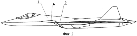
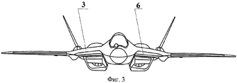
Изобретение поясняется чертежами, где на фиг. 1 изображен маневренный самолет при виде сверху; на фиг. 2 - маневренный самолет при виде сбоку; на фиг. 3 - маневренный самолет при виде спереди.The invention is illustrated by drawings, where in FIG. 1 shows a maneuverable aircraft viewed from above; in FIG. 2 - maneuverable aircraft when viewed from the side; in FIG. 3 - maneuverable aircraft when viewed from the front.
Маневренный самолет содержит фюзеляж 1, стреловидное крыло 2, передние стреловидные наплывы 3, органы управления, включающие вертикальное 4 и горизонтальное 5 оперение, шасси.A maneuverable aircraft contains the
Передние стреловидные наплывы 3 расположены в зоне сочленения головной и средней частей фюзеляжа 1 и снабжены управляемыми поворотными поверхностями 6, при этом оси поворота передних управляемых поверхностей 6 наплывов 3 расположены перпендикулярно или под углом к продольной плоскости самолета.The
Маневренный самолет, включающий сочлененные фюзеляж, крыло и передние стреловидные наплывы большой стреловидности, обладает высокими несущими свойствами на углах атаки больше критических (порядка 26), срыв потока с крыла у такого самолета существенно отодвигается до больших углов атаки (до α=35°).A maneuverable aircraft, including the articulated fuselage, wing and front sweep sweeps of great sweep, has high load-bearing properties at angles of attack greater than critical (about 26), the stall of the flow from the wing of such an aircraft is significantly moved up to large angles of attack (up to α = 35 °).
Сочетание продольной статической неустойчивости на дозвуковых режимах и уменьшенной статической устойчивости на сверхзвуковых скоростях полета существенно расширяет его маневренные возможности.The combination of longitudinal static instability at subsonic modes and reduced static stability at supersonic flight speeds significantly expands its maneuverability.
Однако у статически неустойчивого в продольном канале самолета с наплывами перед крылом существует проблема обеспечения запаса пикирующего момента на углах атаки больше критических. На углах атаки - α, близких к критическим (α=26°), происходят срывы потока на концевых частях крыла, срыв же потока на наплывной части происходит при существенно больших углах атаки. Что приводит к увеличению кабрирующего момента, что в сочетании с резким падением эффективности продольного управления приводит к уменьшению (или даже недостаточности) располагаемого момента на пикирование. В случае непреднамеренного попадания самолета на большие закритические углы атаки (например, на режимах штопора или зависания на больших углах атаки) пикирующего момента тангажа после постановки органов продольного управления для схода с больших углов атаки оказывается недостаточно для перевода самолета на малые углы атаки. Поэтому для обеспечения потребного располагаемого момента ограничивают допустимую предельно-заднюю центровку самолета. Поскольку у современных боевых самолетов подвешиваемые грузы на фюзеляже и крыле в основном сдвигают центр масс самолета назад, приходится уменьшать количество подвешиваемых грузов, а следовательно, ухудшать боевой потенциал самолета.However, for a plane statically unstable in the longitudinal channel with inflows in front of the wing, there is a problem of providing a reserve of diving moment at angles of attack more than critical. At angles of attack - α close to critical (α = 26 °), flow stalls occur at the end parts of the wing, while flow stall at the inflow part occurs at significantly large angles of attack. This leads to an increase in the converting moment, which, combined with a sharp drop in the efficiency of the longitudinal control, leads to a decrease (or even insufficiency) of the available moment for the dive. In the case of an unintentional hit of an aircraft at large supercritical angles of attack (for example, in corkscrew or hovering modes at large angles of attack), the dive moment of pitch after setting the longitudinal control bodies to exit from large angles of attack is not enough to transfer the aircraft to small angles of attack. Therefore, to ensure the required available moment limit the permissible maximum rear-centering of the aircraft. Since in modern combat aircraft, suspended loads on the fuselage and wing mainly shift the center of mass of the aircraft back, it is necessary to reduce the number of suspended loads, and therefore worsen the combat potential of the aircraft.
Кроме того, фиксированный наплыв, повышая подъемную силу крыла, не обеспечивает на малых и средних углах атаки реализацию наилучшего соотношения подъемной силы и сопротивления (поляры) самолета.In addition, a fixed influx, increasing the lift force of the wing, does not provide at small and medium angles of attack the implementation of the best ratio of lift force and drag (polar) of the aircraft.
Для повышения безопасности полетов и его боевой эффективности путем увеличения запасов пикирующего момента и соответственного расширения диапазона допустимых центровок и увеличения средств боевого оснащения самолета, а также реализации наилучшего соотношения подъемной силы и сопротивления передние наплывы 3 снабжены управляемыми поворотными поверхностями 6, а задняя кромка в не отклоненном положении плотно прилегает к передней неподвижной части наплыва 3, расположенной в следе (по потоку).To increase flight safety and combat effectiveness by increasing the reserves of the diving moment and expanding the range of permissible alignments and increasing the means of combat equipment of the aircraft, as well as realizing the best ratio of lifting force and resistance, the
При отклонении управляемых поворотных поверхностей 6 на закритических углах атаки уменьшаются несущие свойства и увеличивается располагаемый пикирующий момент самолета. При отклонении управляемых поворотных поверхностей 6 на малых и средних углах атаки обеспечивается наилучшее соотношение подъемной силы и сопротивления самолета.With the deviation of the controlled
Отклонение управляемых поворотных поверхностей 6 происходит автоматически. Алгоритм отклонения формируется в зависимости от текущего угла атаки (по определенному закону) и положения органа продольного управления - горизонтального оперения 5 и одновременно оптимальным образом сохраняет высокие несущие свойства крыла 2, обеспечивает необходимый запас пикирующего момента на закритических углах атаки и позволяет реализовывать более задние центровки.The deviation of the controlled
Максимальный угол отклонения управляемых поворотных поверхностей 6 на пикирование составляет порядка 60°.The maximum deflection angle of the controlled
Использование управляемых поворотных поверхностей 6 существенно улучшает маневренные характеристики самолета, улучшает его боевые возможности и повышает безопасность его эксплуатации.The use of controlled
Дополнительно управляемые поворотные поверхности 6 используются для торможения самолета после посадки на пробеге после касания ВПП передней стойкой путем их отклонения полностью на пикирование. Управляемые поворотные поверхности 6 могут быть выполнены в следующих вариантах:Additionally controlled
- с осью поворота, расположенной под углом к продольной плоскости самолета;- with an axis of rotation located at an angle to the longitudinal plane of the aircraft;
- с осью поворота, перпендикулярной плоскости симметрии самолета. На сверхзвуковых режимах управляемые поворотные поверхности 6 находятся в зафиксированном положении, т.е. не отклоняются.- with the axis of rotation perpendicular to the plane of symmetry of the aircraft. In supersonic modes, the controlled
Claims (1)
Priority Applications (3)
| Application Number | Priority Date | Filing Date | Title |
|---|---|---|---|
| RU2011154439/11A RU2503584C2 (en) | 2011-12-30 | 2011-12-30 | Maneuvering aircraft |
| CN201280069659.1A CN104684803A (en) | 2011-12-30 | 2012-11-12 | Agile aircraft |
| PCT/RU2012/000928 WO2013100809A1 (en) | 2011-12-30 | 2012-11-12 | Agile aircraft |
Applications Claiming Priority (1)
| Application Number | Priority Date | Filing Date | Title |
|---|---|---|---|
| RU2011154439/11A RU2503584C2 (en) | 2011-12-30 | 2011-12-30 | Maneuvering aircraft |
Publications (2)
| Publication Number | Publication Date |
|---|---|
| RU2011154439A RU2011154439A (en) | 2013-07-10 |
| RU2503584C2 true RU2503584C2 (en) | 2014-01-10 |
Family
ID=48698100
Family Applications (1)
| Application Number | Title | Priority Date | Filing Date |
|---|---|---|---|
| RU2011154439/11A RU2503584C2 (en) | 2011-12-30 | 2011-12-30 | Maneuvering aircraft |
Country Status (3)
| Country | Link |
|---|---|
| CN (1) | CN104684803A (en) |
| RU (1) | RU2503584C2 (en) |
| WO (1) | WO2013100809A1 (en) |
Families Citing this family (1)
| Publication number | Priority date | Publication date | Assignee | Title |
|---|---|---|---|---|
| CN117104549B (en) * | 2023-10-16 | 2026-03-06 | 南京智道航空科技有限公司 | A type of loitering fixed-wing drone |
Citations (4)
| Publication number | Priority date | Publication date | Assignee | Title |
|---|---|---|---|---|
| US4739957A (en) * | 1986-05-08 | 1988-04-26 | Advanced Aerodynamic Concepts, Inc. | Strake fence flap |
| JPH07291192A (en) * | 1994-04-25 | 1995-11-07 | Mitsubishi Heavy Ind Ltd | Variable strake for aircraft |
| RU2223891C1 (en) * | 2002-06-27 | 2004-02-20 | Авруцкий Гарри Израилевич | Method of forming lifting force, aeroplane and method of takeoff and landing |
| RU2412861C1 (en) * | 2009-11-30 | 2011-02-27 | Фатидин Абдурахманович Мухамедов | Mukhamedov's wing |
Family Cites Families (2)
| Publication number | Priority date | Publication date | Assignee | Title |
|---|---|---|---|---|
| CN1143589A (en) * | 1995-08-18 | 1997-02-26 | 梁富泉 | Combined wing aircraft |
| US8272594B2 (en) * | 2009-10-26 | 2012-09-25 | Aerion Corporation | Laminar flow wing optimized for supersonic cruise aircraft |
-
2011
- 2011-12-30 RU RU2011154439/11A patent/RU2503584C2/en active
-
2012
- 2012-11-12 WO PCT/RU2012/000928 patent/WO2013100809A1/en not_active Ceased
- 2012-11-12 CN CN201280069659.1A patent/CN104684803A/en active Pending
Patent Citations (4)
| Publication number | Priority date | Publication date | Assignee | Title |
|---|---|---|---|---|
| US4739957A (en) * | 1986-05-08 | 1988-04-26 | Advanced Aerodynamic Concepts, Inc. | Strake fence flap |
| JPH07291192A (en) * | 1994-04-25 | 1995-11-07 | Mitsubishi Heavy Ind Ltd | Variable strake for aircraft |
| RU2223891C1 (en) * | 2002-06-27 | 2004-02-20 | Авруцкий Гарри Израилевич | Method of forming lifting force, aeroplane and method of takeoff and landing |
| RU2412861C1 (en) * | 2009-11-30 | 2011-02-27 | Фатидин Абдурахманович Мухамедов | Mukhamedov's wing |
Also Published As
| Publication number | Publication date |
|---|---|
| RU2011154439A (en) | 2013-07-10 |
| WO2013100809A1 (en) | 2013-07-04 |
| CN104684803A (en) | 2015-06-03 |
Similar Documents
| Publication | Publication Date | Title |
|---|---|---|
| US9694908B2 (en) | Convertiplane (variants) | |
| US8752788B2 (en) | Wing and a multiple propeller aircraft | |
| CN108045575B (en) | Short-distance take-off vertical landing aircraft | |
| US20110114795A1 (en) | Aerodynamic Flap and Wing | |
| WO2012026846A1 (en) | Aircraft with an integral aerodynamic configuration | |
| CN111315655A (en) | Assembly of three composite wings for air, water, land or space vehicles | |
| CN105083551A (en) | Tilt rotary-wing aircraft and control method thereof | |
| CN108082471B (en) | a variant supersonic aircraft | |
| CN106314761A (en) | All-moving wing mechanism applied to small compound helicopter | |
| CN106672205B (en) | Layout of a Large Variable Sweep Supersonic Aircraft | |
| EA028045B1 (en) | Fuselage and method for reducing drag | |
| US10011350B2 (en) | Vertical take-off and landing drag rudder | |
| US11554849B2 (en) | Tailless aircraft | |
| RU2503584C2 (en) | Maneuvering aircraft | |
| RU2667410C1 (en) | Aerodynamic surface and airframe of aircraft | |
| US20100001121A1 (en) | System for tilting a power unit | |
| US2430820A (en) | Airplane of low aspect ratio | |
| RU2557685C2 (en) | "flying wing" configuration aircraft | |
| RU128182U1 (en) | SECURITY PLAN (OPTIONS) | |
| CN203512023U (en) | Pitching control rudder surface on tail of airframe of airplane | |
| CN107499505B (en) | Three-wing unmanned aerial vehicle | |
| CN113306698B (en) | Double-feather type wing tip winglet device with variable inclination angle | |
| US3022965A (en) | Aircraft wing | |
| CN115042957A (en) | Aircraft with vert variant fin | |
| TWI683767B (en) | Tailless aircraft |
Legal Events
| Date | Code | Title | Description |
|---|---|---|---|
| TC4A | Change in inventorship |
Effective date: 20141210 |