RU2503515C2 - Method of making return bends - Google Patents
Method of making return bends Download PDFInfo
- Publication number
- RU2503515C2 RU2503515C2 RU2012102221/02A RU2012102221A RU2503515C2 RU 2503515 C2 RU2503515 C2 RU 2503515C2 RU 2012102221/02 A RU2012102221/02 A RU 2012102221/02A RU 2012102221 A RU2012102221 A RU 2012102221A RU 2503515 C2 RU2503515 C2 RU 2503515C2
- Authority
- RU
- Russia
- Prior art keywords
- external
- next section
- consumable electrode
- mold
- metal
- Prior art date
Links
- 238000004519 manufacturing process Methods 0.000 title description 6
- 238000000034 method Methods 0.000 claims abstract description 17
- 238000009434 installation Methods 0.000 claims abstract description 8
- 239000002131 composite material Substances 0.000 claims abstract description 7
- 229910001338 liquidmetal Inorganic materials 0.000 claims abstract description 7
- 238000002425 crystallisation Methods 0.000 claims description 4
- 230000008025 crystallization Effects 0.000 claims description 4
- 239000013078 crystal Substances 0.000 claims 1
- 239000002184 metal Substances 0.000 abstract description 15
- 238000005266 casting Methods 0.000 abstract description 5
- 238000010327 methods by industry Methods 0.000 abstract 1
- 239000000126 substance Substances 0.000 abstract 1
- 239000002893 slag Substances 0.000 description 7
- 238000005452 bending Methods 0.000 description 3
- 230000015572 biosynthetic process Effects 0.000 description 3
- 238000000605 extraction Methods 0.000 description 2
- 239000000155 melt Substances 0.000 description 2
- 229910000831 Steel Inorganic materials 0.000 description 1
- 150000001875 compounds Chemical class 0.000 description 1
- 238000011437 continuous method Methods 0.000 description 1
- 238000010586 diagram Methods 0.000 description 1
- 238000005516 engineering process Methods 0.000 description 1
- 239000010959 steel Substances 0.000 description 1
Images
Landscapes
- Continuous Casting (AREA)
Abstract
Description
Изобретение относится к производству крутоизогнутых отводов с использованием электрошлаковой технологии.The invention relates to the production of bent bends using electroslag technology.
Известен способ изготовления крутоизогнутых отводов, включающий протяжку трубной заготовки по рогообразному сердечнику в криволинейную заготовку с размером по диаметру, равным диаметру отвода, и догиб криволинейной заготовки в штампе до размеров отвода (А.И. Гальперин, Машины и оборудование для гнутья труб, М.: Машиностроение, 1967, стр.143-153), патент РФ №2247163).A known method of manufacturing steeply curved bends, including pulling a pipe billet along the horn-shaped core into a curved billet with a diameter equal to the diameter of the bend, and bending the curved billet in the stamp to the size of the bend (A.I. Halperin, Machines and equipment for bending pipes, M. : Engineering, 1967, pp. 143-153), RF patent No. 227163).
Недостатком способа являются большие деформации кольцевого растяжения металла трубной заготовки в процессе протяжки по рогообразному сердечнику, большой расход металла, низкое качество детали, высокая трудоемкость изготовления.The disadvantage of this method is the large deformation of the annular tension of the metal of the tubular billet during the broaching process along the horn-shaped core, high metal consumption, low quality of the part, high complexity of manufacturing.
Известен способ электрошлакового переплава (ЭШП), реализуемый установкой по патенту RU №2247163, МПК B23K 25/00 и заключающийся в переплаве расходуемого электрода под слоем шлака с одновременной кристаллизацией оплавленного металла.A known method of electroslag remelting (ESR), implemented by the installation according to the patent RU No. 2247163, IPC B23K 25/00 and consisting in remelting the sacrificial electrode under a slag layer with simultaneous crystallization of the molten metal.
Указанный способ и установка для его осуществления могут быть использованы для электрошлаковой наплавки труб, но не позволяют получать трубы непрерывной вытяжки и крутоизогнутые отводы труб.The specified method and installation for its implementation can be used for electroslag surfacing of pipes, but do not allow to obtain pipes for continuous drawing and bent pipe bends.
Наиболее близким к заявляемому является способ полунепрерывного вертикального литья труб, по которому жидкий металл подают из литниковой системы в кольцевое пространство между наружным и внутренним кристаллизаторами. После формирования трубы заданной длины поступление жидкого металла в кольцевое пространство между наружным и внутренним кристаллизаторами прекращают и извлекают трубу. Для устранения зависания затвердевающей корочки используют возвратно-поступательное движение кристаллизатора вдоль оси отливки, встряхивание или вибрацию (Ефимов В.А. - Специальные способы литья, с.557-561 (справочник, 1991 г.).Closest to the claimed is a method of semi-continuous vertical pipe casting, in which liquid metal is fed from the gate system into the annular space between the outer and inner molds. After the formation of the pipe of a given length, the flow of liquid metal into the annular space between the outer and inner molds is stopped and the pipe is removed. To eliminate the hardening of the hardening crust, the reciprocating motion of the mold along the casting axis, shaking or vibration are used (V. Efimov - Special casting methods, p. 557-561 (reference book, 1991).
Недостатком данного способа является то, что толщина стенки отливаемых труб ограничена и составляет 7-30 мм. Недостатком способа являются также узкие функциональные возможности, а именно: невозможность изготовления крутоизогнутых отводов труб.The disadvantage of this method is that the wall thickness of the cast pipes is limited and is 7-30 mm The disadvantage of this method is also narrow functionality, namely: the impossibility of manufacturing steeply curved pipe bends.
Техническим результатом изобретения является расширение функциональных возможностей способа, а именно, обеспечение изготовления толстостенных крутоизогнутых отводов труб.The technical result of the invention is to expand the functionality of the method, namely, to ensure the manufacture of thick-walled steeply curved pipe bends.
Указанный технический результат достигается тем, что трубную заготовку формируют кристаллизацией жидкого металла, который подают в кольцевое пространство между внешним и внутренним кристаллизатором с одновременным перемещением последних, согласно заявляемому изобретению, осуществляют электрошлаковый переплав полого расходуемого электрода, диаметр которого соответствует диаметру трубного отвода, формирование трубного отвода осуществляют за несколько операций, каждой из которых предшествует установка очередной секции составного внешнего кристаллизатора, перемещение кристаллизаторов после установки очередной секции внешнего кристаллизатора осуществляют встречно: внутренний кристаллизатор перемещают вертикально вверх внутри полого расходуемого электрода, а внешний составной - опускают по заданному радиусу трубного отвода вниз до достижения жидким металлом краев очередной секции.The specified technical result is achieved by the fact that the tubular billet is formed by crystallization of liquid metal, which is fed into the annular space between the external and internal crystallizer with the simultaneous movement of the latter, according to the claimed invention, electroslag remelting of the hollow consumable electrode, the diameter of which corresponds to the diameter of the pipe branch, the formation of the pipe branch carry out in several operations, each of which is preceded by the installation of the next section of the composite After the installation of the next section of the external crystallizer, the molds are moved counterclockwise: the internal mold is moved vertically upward inside the hollow consumable electrode, and the external compound is lowered downward along the specified radius of the pipe branch until the edges of the next section reach the liquid metal.
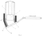
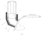
Сущность изобретения поясняется чертежом, где на фиг.1 показана схема установки для осуществления способа на начальной стадии формирования трубного отвода электрошлаковым переплавом расходуемого электрода; на фиг.2 - то же после установки второй секции составного внешнего кристаллизатора; на фиг.3 - одна из завершающих стадий формирования трубного отвода заявляемым способом.The invention is illustrated in the drawing, where Fig.1 shows a diagram of an installation for implementing the method at the initial stage of forming a pipe outlet by electroslag remelting of a consumable electrode; figure 2 is the same after installing the second section of the composite external mold; figure 3 is one of the final stages of the formation of the pipe branch of the claimed method.
Способ осуществляется следующим образом.The method is as follows.
На стол 1 гидравлического манипулятора устанавливают затравку 2 в виде кольца, диаметр которого соответствует диаметру изготавливаемого отвода. Внутрь кольца опускают внутренний охлаждаемый кристаллизатор 3. Затем на стол 1 гидравлического манипулятора устанавливают первую секцию 4а внешнего кристаллизатора 4. На полый расходуемый электрод 5 подают напряжение, и он начинает опускаться вниз. После касания электрода затравки по нему начинает протекать ток за счет, которого происходит его плавление.On the table 1 of the hydraulic manipulator set the
Оплавленный металл проходит через шлак в кольцевом пространстве между внешним и внутренним кристаллизаторами и кристаллизуется на затравке 2.The molten metal passes through the slag in the annular space between the external and internal crystallizers and crystallizes on the
По мере кристаллизации оплавленного металла и заполнения кольцевого пространства между кристаллизаторами 3 и 4, стол 1 гидравлического манипулятора опускается по радиусу изготавливаемого отвода. При этом вследствие усадки кристаллизующегося металла, возникает сила, выталкивающая вверх внутренний кристаллизатор. Таким образом, внешний и внутренний кристаллизаторы движутся встречно.As crystallization of the molten metal and filling of the annular space between the molds 3 and 4, the table 1 of the hydraulic manipulator is lowered along the radius of the manufactured branch. In this case, due to the shrinkage of the crystallizing metal, there is a force pushing up the inner mold. Thus, the external and internal crystallizers move counterclockwise.
Когда шлак с металлом достигнет верхнего уровня первой секции 4а внешнего кристаллизатора 4, устанавливают следующую секцию 4б внешнего кристаллизатора 4. При достижении шлаком и металлом краев второй секции 4б внешнего кристаллизатора, вновь устанавливают следующую секцию внешнего кристаллизатора 4с и цикл повторяется. Так продолжается до вытяжки полного размера отвода 6. Количество устанавливаемых секций зависит от длины отвода.When the slag with metal reaches the upper level of the first section 4a of the external crystallizer 4, the next section 4b of the external crystallizer 4 is installed. When the slag and the metal reach the edges of the second section 4b of the external crystallizer, the next section of the external crystallizer 4c is again set and the cycle repeats. This continues until the exhaust of the full size of the
При достижении заданных размеров отвода полый расходуемый электрод 5 поднимают на 500-600 мм вверх, отключают источник напряжения, дают изготовленной заготовке остыть до температуры 60-40°C, разбирают посекционно внешний кристаллизатор 4, откручивают затравку 2 от стола 1 и извлекают отвод 6 вместе с затравкой 2.Upon reaching the specified dimensions of the outlet, the hollow
Пример осуществления способа.An example implementation of the method.
Изготавливали отвод Do=430 мм с толщиной стенки Bо=35 мм, средним радиусом изгиба отвода Rcp=600 мм. Отвод предназначался для магистрального трубопровода.A bend D o = 430 mm was made with a wall thickness B o = 35 mm and an average bend radius R cp = 600 mm. The branch was intended for the main pipeline.
На столе гидравлического манипулятора закрепляют затравку (кольцевую заготовку) с размерами: Dзатр.=430 мм, толщина стенки Bзатр.=35 мм , высота Hзатр.=50 мм.On the table of the hydraulic manipulator, a seed (ring billet) is fixed with dimensions: D ex. = 430 mm, wall thickness B ex. = 35 mm, height H ex. = 50 mm.
Во внутреннее кольцевое пространство затравки опускают внутренний кристаллизатор на глубину, равную примерно половине высоты затравки - 25 мм. Диаметр внутреннего кристаллизатора при этом выбирают по формуле D-2В-z, где D - диаметр затравки, B - толщина стенки затравки, z - необходимый зазор. В данном случае 430 мм - 2×35 мм - 5 мм = 355 мм.In the inner annular space of the seed, the inner mold is lowered to a depth equal to about half the height of the seed - 25 mm. The diameter of the inner crystallizer is selected according to the formula D-2B-z, where D is the diameter of the seed, B is the thickness of the wall of the seed, z is the required clearance. In this case, 430 mm - 2 × 35 mm - 5 mm = 355 mm.
Устанавливают на стол гидравлического манипулятора первую секцию внешнего кристаллизатора с обеспечением зазора между расходуемым электродом и внешним кристаллизатором.The first section of the external mold is mounted on the table of the hydraulic manipulator, providing a gap between the consumable electrode and the external mold.
При среднем радиусе изгиба изготавливаемого отвода Rсp.=600 мм и его диаметре D=430 мм, максимальный радиус изгиба отвода составит R1=815 мм, а минимальный - R2=385 мм. В связи с этим образующая высота (максимальный радиус изгиба отвода) наружной и внутренней стенок (минимальный радиус изгиба отвода) внешнего кристаллизатора должна быть разной. Высота наружной стенки каждой секции внешнего кристаллизатора определяется по формуле Lн=2πR1/4n, а высота внутренней стенки внешнего кристаллизатора определяется по формуле Lв=2πR2/4n, где R1, R2 - внешний и внутренний радиус изгиба отвода соответственно; n - количество секций внешнего кристаллизатора.With an average bend radius of the manufactured outlet R cp. = 600 mm and its diameter D = 430 mm, the maximum bend radius of the branch will be R 1 = 815 mm, and the minimum - R 2 = 385 mm. In this regard, the forming height (maximum bend radius of the bend) of the outer and inner walls (minimum bend radius of the bend) of the external mold should be different. The height of the outer wall of each section of the external mold is determined by the formula L n = 2πR 1 / 4n, and the height of the inner wall of the external mold is determined by the formula L in = 2πR 2 / 4n, where R 1 , R 2 are the external and internal bending radius of the branch, respectively; n is the number of sections of the external mold.
При n=6 получаем: Lн=214 мм; Lв=101 мм.When n = 6 we get: L n = 214 mm; L in = 101 mm.
После установки первой секции внешнего кристаллизатора на полый расходуемый электрод подают напряжение, за счет которого происходит его плавление.After installing the first section of the external crystallizer, a voltage is applied to the hollow consumable electrode, due to which it melts.
Оплавленный металл проходит через шлак в кольцевом пространстве между внешним и внутренним кристаллизаторами и кристаллизуется на затравке.The molten metal passes through the slag in the annular space between the external and internal molds and crystallizes on the seed.
При этом по мере оплавления расходуемого электрода и кристаллизации электрошлакового металла, внутренний кристаллизатор поднимается на 5-8 мм. По команде, поступающей с блока управления, гидравлический манипулятор опускает внешний кристаллизатор на эту же величину (5-8 мм) по заданному радиусу трубного отвода.In this case, as the consumable electrode is melted and the electroslag metal crystallizes, the internal mold rises by 5-8 mm. On command from the control unit, the hydraulic manipulator lowers the external mold by the same amount (5-8 mm) along the specified radius of the pipe branch.
Когда шлак с металлом достигнет верхнего уровня первой секции внешнего кристаллизатора, устанавливают следующую секцию внешнего кристаллизатора. При достижении шлаком и металлом краев второй секции внешнего кристаллизатора, вновь устанавливают следующую секцию и цикл повторяется. Так продолжается до вытяжки полного размера отвода.When the slag with the metal reaches the upper level of the first section of the external mold, set the next section of the external mold. When the slag and metal reach the edges of the second section of the external crystallizer, the next section is again set and the cycle repeats. This continues until the exhaust of the full size of the tap.
Вытяжка крутоизогнутых трубных отводов непрерывным способом электрошлакового переплава позволяет обеспечить их высокие физические и механические свойства, изготавливать отводы практически любой толщины.Extraction of steeply bent pipe bends by the continuous method of electroslag remelting ensures their high physical and mechanical properties, and produces bends of almost any thickness.
С другой стороны, метод ЭШП позволяет получить металл, обладающий высокой свариваемостью, что является необходимым качеством трубных отводов. Процесс непрерывной вытяжки отводов позволяет значительно расширить номенклатуру марок стали, из которых можно получать отводы.On the other hand, the ESR method allows to obtain a metal with high weldability, which is a necessary quality of pipe bends. The process of continuous extraction of bends allows you to significantly expand the range of steel grades from which bends can be obtained.
Claims (1)
Priority Applications (1)
| Application Number | Priority Date | Filing Date | Title |
|---|---|---|---|
| RU2012102221/02A RU2503515C2 (en) | 2012-01-23 | 2012-01-23 | Method of making return bends |
Applications Claiming Priority (1)
| Application Number | Priority Date | Filing Date | Title |
|---|---|---|---|
| RU2012102221/02A RU2503515C2 (en) | 2012-01-23 | 2012-01-23 | Method of making return bends |
Publications (2)
| Publication Number | Publication Date |
|---|---|
| RU2012102221A RU2012102221A (en) | 2013-07-27 |
| RU2503515C2 true RU2503515C2 (en) | 2014-01-10 |
Family
ID=49155409
Family Applications (1)
| Application Number | Title | Priority Date | Filing Date |
|---|---|---|---|
| RU2012102221/02A RU2503515C2 (en) | 2012-01-23 | 2012-01-23 | Method of making return bends |
Country Status (1)
| Country | Link |
|---|---|
| RU (1) | RU2503515C2 (en) |
Citations (1)
| Publication number | Priority date | Publication date | Assignee | Title |
|---|---|---|---|---|
| RU2247163C2 (en) * | 2002-01-08 | 2005-02-27 | Шепелев Николай Васильевич | Installation for electroslag refining, welding and surfacing metals |
-
2012
- 2012-01-23 RU RU2012102221/02A patent/RU2503515C2/en not_active IP Right Cessation
Patent Citations (1)
| Publication number | Priority date | Publication date | Assignee | Title |
|---|---|---|---|---|
| RU2247163C2 (en) * | 2002-01-08 | 2005-02-27 | Шепелев Николай Васильевич | Installation for electroslag refining, welding and surfacing metals |
Non-Patent Citations (2)
| Title |
|---|
| ЕФИМОВ В.А. Специальные способы литья. Справочник. - М.: Металлургия, 1991, с.557-561. * |
| Электрошлаковые печи /Под ред. академика Б.Е. Патона. - Киев: Наукова Думка, 1976, с.318-320. * |
Also Published As
| Publication number | Publication date |
|---|---|
| RU2012102221A (en) | 2013-07-27 |
Similar Documents
| Publication | Publication Date | Title |
|---|---|---|
| JP2012061518A (en) | Free casting method, free casting apparatus, and casting | |
| JP5755591B2 (en) | Cast body manufacturing method and manufacturing apparatus | |
| CN109663892B (en) | Progressive solidification forming device for large cast ingot or casting blank | |
| EP3960337C0 (en) | PROCESS FOR PRODUCING MAGNESIUM-LITHIUM ALLOY BY GAS CO-CONDENSATION | |
| CN105478690B (en) | Graphite jig for up-drawing method crystallizer | |
| RU2015148151A (en) | CASTING FORM FOR PRODUCING SINGLE CRYSTAL CASTINGS | |
| RU2503515C2 (en) | Method of making return bends | |
| CN201889398U (en) | Casting device of vertical copper and copper alloy thick-wall hollow casting ingot | |
| UA106917C2 (en) | METHOD OF PRODUCTION OF SEAMLESS PIPES | |
| CN104117630A (en) | Main oil gallery sand core mold of large engine body and core manufacturing method | |
| CN101612661B (en) | Heavy caliber uniform section hollow steel ingot device for electro-slag continuous stripping | |
| CN104209481B (en) | Hollow steel ingot casting mold and adopt its cast hollow steel ingot method | |
| SU822759A3 (en) | Device for electroslag remelting | |
| CN103128238A (en) | Method utilizing slab crystallizer to continuously pour square billets | |
| RU124683U1 (en) | INSTALLATION FOR ELECTRIC SLAG RELEASING | |
| CN110293142B (en) | A die for copper alloy semi-solid extrusion pipe | |
| RU2205724C1 (en) | Method of continuous or semicontinuous casting of tubular blanks of copper and its alloys | |
| CN102699291B (en) | Crystallizer device for continuously casting hollow tube blanks | |
| RU165178U1 (en) | DEVICE FOR CASTING PRODUCTS FROM METALS AND ALLOYS | |
| CN110125347B (en) | High-momentum rapid prototyping preparation device and method of equiaxed-crystalline aluminum alloy | |
| CN107363242A (en) | A kind of large tank electro-slag continuous casting technique | |
| WO2013000555A3 (en) | Method for producing a mold tube | |
| CN107159854A (en) | Large diameter copper pipe casts draw-off gear | |
| CN107746971A (en) | Method for casting titanium or titanium alloy hollow ingot by using electron beam cooling bed furnace | |
| SU997971A1 (en) | Method of producing bi metalic tubular articles |
Legal Events
| Date | Code | Title | Description |
|---|---|---|---|
| MM4A | The patent is invalid due to non-payment of fees |
Effective date: 20150124 |