RU2502666C2 - Device and apparatus for preparation and dispensing of mixed products composed of main fluid and diluent - Google Patents
Device and apparatus for preparation and dispensing of mixed products composed of main fluid and diluent Download PDFInfo
- Publication number
- RU2502666C2 RU2502666C2 RU2009129940/12A RU2009129940A RU2502666C2 RU 2502666 C2 RU2502666 C2 RU 2502666C2 RU 2009129940/12 A RU2009129940/12 A RU 2009129940/12A RU 2009129940 A RU2009129940 A RU 2009129940A RU 2502666 C2 RU2502666 C2 RU 2502666C2
- Authority
- RU
- Russia
- Prior art keywords
- diluent
- liquid
- channel
- mixing
- pump
- Prior art date
Links
Images


Classifications
-
- B—PERFORMING OPERATIONS; TRANSPORTING
- B67—OPENING, CLOSING OR CLEANING BOTTLES, JARS OR SIMILAR CONTAINERS; LIQUID HANDLING
- B67D—DISPENSING, DELIVERING OR TRANSFERRING LIQUIDS, NOT OTHERWISE PROVIDED FOR
- B67D1/00—Apparatus or devices for dispensing beverages on draught
- B67D1/0015—Apparatus or devices for dispensing beverages on draught the beverage being prepared by mixing at least two liquid components
- B67D1/0016—Apparatus or devices for dispensing beverages on draught the beverage being prepared by mixing at least two liquid components the beverage being stored in an intermediate container before dispensing, i.e. pre-mix dispensers
-
- B—PERFORMING OPERATIONS; TRANSPORTING
- B01—PHYSICAL OR CHEMICAL PROCESSES OR APPARATUS IN GENERAL
- B01F—MIXING, e.g. DISSOLVING, EMULSIFYING OR DISPERSING
- B01F25/00—Flow mixers; Mixers for falling materials, e.g. solid particles
- B01F25/30—Injector mixers
-
- B—PERFORMING OPERATIONS; TRANSPORTING
- B01—PHYSICAL OR CHEMICAL PROCESSES OR APPARATUS IN GENERAL
- B01F—MIXING, e.g. DISSOLVING, EMULSIFYING OR DISPERSING
- B01F25/00—Flow mixers; Mixers for falling materials, e.g. solid particles
-
- B—PERFORMING OPERATIONS; TRANSPORTING
- B01—PHYSICAL OR CHEMICAL PROCESSES OR APPARATUS IN GENERAL
- B01F—MIXING, e.g. DISSOLVING, EMULSIFYING OR DISPERSING
- B01F25/00—Flow mixers; Mixers for falling materials, e.g. solid particles
- B01F25/40—Static mixers
- B01F25/42—Static mixers in which the mixing is affected by moving the components jointly in changing directions, e.g. in tubes provided with baffles or obstructions
- B01F25/43—Mixing tubes, e.g. wherein the material is moved in a radial or partly reversed direction
- B01F25/433—Mixing tubes wherein the shape of the tube influences the mixing, e.g. mixing tubes with varying cross-section or provided with inwardly extending profiles
- B01F25/4332—Mixers with a strong change of direction in the conduit for homogenizing the flow
-
- B—PERFORMING OPERATIONS; TRANSPORTING
- B01—PHYSICAL OR CHEMICAL PROCESSES OR APPARATUS IN GENERAL
- B01F—MIXING, e.g. DISSOLVING, EMULSIFYING OR DISPERSING
- B01F25/00—Flow mixers; Mixers for falling materials, e.g. solid particles
- B01F25/40—Static mixers
- B01F25/42—Static mixers in which the mixing is affected by moving the components jointly in changing directions, e.g. in tubes provided with baffles or obstructions
- B01F25/43—Mixing tubes, e.g. wherein the material is moved in a radial or partly reversed direction
- B01F25/433—Mixing tubes wherein the shape of the tube influences the mixing, e.g. mixing tubes with varying cross-section or provided with inwardly extending profiles
- B01F25/4336—Mixers with a diverging cross-section
-
- B—PERFORMING OPERATIONS; TRANSPORTING
- B01—PHYSICAL OR CHEMICAL PROCESSES OR APPARATUS IN GENERAL
- B01F—MIXING, e.g. DISSOLVING, EMULSIFYING OR DISPERSING
- B01F35/00—Accessories for mixers; Auxiliary operations or auxiliary devices; Parts or details of general application
- B01F35/80—Forming a predetermined ratio of the substances to be mixed
- B01F35/83—Forming a predetermined ratio of the substances to be mixed by controlling the ratio of two or more flows, e.g. using flow sensing or flow controlling devices
- B01F35/831—Forming a predetermined ratio of the substances to be mixed by controlling the ratio of two or more flows, e.g. using flow sensing or flow controlling devices using one or more pump or other dispensing mechanisms for feeding the flows in predetermined proportion, e.g. one of the pumps being driven by one of the flows
-
- B—PERFORMING OPERATIONS; TRANSPORTING
- B67—OPENING, CLOSING OR CLEANING BOTTLES, JARS OR SIMILAR CONTAINERS; LIQUID HANDLING
- B67D—DISPENSING, DELIVERING OR TRANSFERRING LIQUIDS, NOT OTHERWISE PROVIDED FOR
- B67D1/00—Apparatus or devices for dispensing beverages on draught
-
- B—PERFORMING OPERATIONS; TRANSPORTING
- B67—OPENING, CLOSING OR CLEANING BOTTLES, JARS OR SIMILAR CONTAINERS; LIQUID HANDLING
- B67D—DISPENSING, DELIVERING OR TRANSFERRING LIQUIDS, NOT OTHERWISE PROVIDED FOR
- B67D1/00—Apparatus or devices for dispensing beverages on draught
- B67D1/0015—Apparatus or devices for dispensing beverages on draught the beverage being prepared by mixing at least two liquid components
- B67D1/0021—Apparatus or devices for dispensing beverages on draught the beverage being prepared by mixing at least two liquid components the components being mixed at the time of dispensing, i.e. post-mix dispensers
- B67D1/0022—Apparatus or devices for dispensing beverages on draught the beverage being prepared by mixing at least two liquid components the components being mixed at the time of dispensing, i.e. post-mix dispensers the apparatus comprising means for automatically controlling the amount to be dispensed
- B67D1/0027—Apparatus or devices for dispensing beverages on draught the beverage being prepared by mixing at least two liquid components the components being mixed at the time of dispensing, i.e. post-mix dispensers the apparatus comprising means for automatically controlling the amount to be dispensed control of the amount of one component, the amount of the other components(s) being dependent on that control
- B67D1/0029—Apparatus or devices for dispensing beverages on draught the beverage being prepared by mixing at least two liquid components the components being mixed at the time of dispensing, i.e. post-mix dispensers the apparatus comprising means for automatically controlling the amount to be dispensed control of the amount of one component, the amount of the other components(s) being dependent on that control based on volumetric dosing
- B67D1/003—Apparatus or devices for dispensing beverages on draught the beverage being prepared by mixing at least two liquid components the components being mixed at the time of dispensing, i.e. post-mix dispensers the apparatus comprising means for automatically controlling the amount to be dispensed control of the amount of one component, the amount of the other components(s) being dependent on that control based on volumetric dosing by means of a dosing chamber
- B67D1/0031—Apparatus or devices for dispensing beverages on draught the beverage being prepared by mixing at least two liquid components the components being mixed at the time of dispensing, i.e. post-mix dispensers the apparatus comprising means for automatically controlling the amount to be dispensed control of the amount of one component, the amount of the other components(s) being dependent on that control based on volumetric dosing by means of a dosing chamber in the form of a metering pump
-
- B—PERFORMING OPERATIONS; TRANSPORTING
- B67—OPENING, CLOSING OR CLEANING BOTTLES, JARS OR SIMILAR CONTAINERS; LIQUID HANDLING
- B67D—DISPENSING, DELIVERING OR TRANSFERRING LIQUIDS, NOT OTHERWISE PROVIDED FOR
- B67D1/00—Apparatus or devices for dispensing beverages on draught
- B67D1/0042—Details of specific parts of the dispensers
- B67D1/0043—Mixing devices for liquids
- B67D1/0044—Mixing devices for liquids for mixing inside the dispensing nozzle
- B67D1/0046—Mixing chambers
-
- B—PERFORMING OPERATIONS; TRANSPORTING
- B67—OPENING, CLOSING OR CLEANING BOTTLES, JARS OR SIMILAR CONTAINERS; LIQUID HANDLING
- B67D—DISPENSING, DELIVERING OR TRANSFERRING LIQUIDS, NOT OTHERWISE PROVIDED FOR
- B67D1/00—Apparatus or devices for dispensing beverages on draught
- B67D1/0042—Details of specific parts of the dispensers
- B67D1/0078—Ingredient cartridges
- B67D1/0079—Ingredient cartridges having their own dispensing means
-
- B—PERFORMING OPERATIONS; TRANSPORTING
- B67—OPENING, CLOSING OR CLEANING BOTTLES, JARS OR SIMILAR CONTAINERS; LIQUID HANDLING
- B67D—DISPENSING, DELIVERING OR TRANSFERRING LIQUIDS, NOT OTHERWISE PROVIDED FOR
- B67D1/00—Apparatus or devices for dispensing beverages on draught
- B67D1/08—Details
- B67D1/0801—Details of beverage containers, e.g. casks, kegs
- B67D2001/0811—Details of beverage containers, e.g. casks, kegs provided with coded information
-
- Y—GENERAL TAGGING OF NEW TECHNOLOGICAL DEVELOPMENTS; GENERAL TAGGING OF CROSS-SECTIONAL TECHNOLOGIES SPANNING OVER SEVERAL SECTIONS OF THE IPC; TECHNICAL SUBJECTS COVERED BY FORMER USPC CROSS-REFERENCE ART COLLECTIONS [XRACs] AND DIGESTS
- Y10—TECHNICAL SUBJECTS COVERED BY FORMER USPC
- Y10T—TECHNICAL SUBJECTS COVERED BY FORMER US CLASSIFICATION
- Y10T137/00—Fluid handling
- Y10T137/8593—Systems
- Y10T137/87571—Multiple inlet with single outlet
- Y10T137/87587—Combining by aspiration
- Y10T137/87595—Combining of three or more diverse fluids
-
- Y—GENERAL TAGGING OF NEW TECHNOLOGICAL DEVELOPMENTS; GENERAL TAGGING OF CROSS-SECTIONAL TECHNOLOGIES SPANNING OVER SEVERAL SECTIONS OF THE IPC; TECHNICAL SUBJECTS COVERED BY FORMER USPC CROSS-REFERENCE ART COLLECTIONS [XRACs] AND DIGESTS
- Y10—TECHNICAL SUBJECTS COVERED BY FORMER USPC
- Y10T—TECHNICAL SUBJECTS COVERED BY FORMER US CLASSIFICATION
- Y10T137/00—Fluid handling
- Y10T137/8593—Systems
- Y10T137/87571—Multiple inlet with single outlet
- Y10T137/87652—With means to promote mixing or combining of plural fluids
- Y10T137/8766—With selectively operated flow control means
Landscapes
- Chemical & Material Sciences (AREA)
- Chemical Kinetics & Catalysis (AREA)
- Dispersion Chemistry (AREA)
- Devices For Dispensing Beverages (AREA)
- Accessories For Mixers (AREA)
- Loading And Unloading Of Fuel Tanks Or Ships (AREA)
- Non-Alcoholic Beverages (AREA)
- Confectionery (AREA)
- Bakery Products And Manufacturing Methods Therefor (AREA)
- Closures For Containers (AREA)
Abstract
Description
Настоящее изобретение относится к аппарату для приготовления и отпуска смеси, состоящей из основной жидкости и разбавителя. В частности, изобретение относится к приготовлению и раздаче напитков или других жидких пищевых продуктов, осуществляемым путем дозирования жидкого пищевого продукта и смешивания его с разбавителем. Настоящее изобретение находит применение при раздаче напитков, пенистых или не пенистых, горячих или холодных, содержащих жидкий концентрат и воду, гигиенично, легко и быстро, причем даже в том случае, когда объемы раздачи продукта велики.The present invention relates to an apparatus for preparing and dispensing a mixture consisting of a basic liquid and a diluent. In particular, the invention relates to the preparation and distribution of drinks or other liquid food products by dispensing a liquid food product and mixing it with a diluent. The present invention finds application in the distribution of beverages, frothy or non-frothy, hot or cold, containing liquid concentrate and water, hygienically, easily and quickly, even when the volumes of distribution of the product are large.
В известных автоматах по продаже напитков эти напитки производят из жидкого концентрата или порошка, содержащегося в емкостях. Жидкий концентрат или порошок дозируют, затем смешивают с разбавителем, обычно с горячей или холодной водой, внутри дозирующего автомата, пропуская через трубки, насосы и смесительные резервуары. Перемешивание обычно производят с помощью механической мешалки, размещенной внутри камеры. Таким образом, известное приготовление этих напитков требует большого объема работ по обслуживанию и очистке, необходимого для того, чтобы поддерживать элементы конструкции, постоянно контактирующие с пищевым продуктом, чистыми и избежать опасности загрязнения и размножения бактерий. Вышеупомянутые аппараты, кроме того, олицетворяют значительные капиталовложения, приходящиеся на долю обслуживающих операторов. Наконец, эти аппараты имеют недостаток, заключающийся в том, что они не универсальны с точки зрения выбора отпускаемых напитков, хотя текущая тенденция заключается именно в расширении выбора горячих, холодных, пенистых или не пенистых напитков.In well-known beverage vending machines, these drinks are made from liquid concentrate or powder contained in containers. The liquid concentrate or powder is metered, then mixed with a diluent, usually hot or cold water, inside the metering machine, passing through tubes, pumps and mixing tanks. Mixing is usually carried out using a mechanical stirrer placed inside the chamber. Thus, the known preparation of these drinks requires a large amount of maintenance and cleaning work necessary in order to keep the structural elements that are constantly in contact with the food product clean and avoid the risk of contamination and the growth of bacteria. The aforementioned devices, in addition, represent a significant investment in the share of serving operators. Finally, these devices have the disadvantage that they are not universal in terms of the choice of dispensed drinks, although the current trend is precisely to expand the selection of hot, cold, foamy or non-foamy drinks.
Действительно, известны аппараты для отпуска фруктовых соков из разового или повторно используемого сменного блока, содержащего концентрат и объединенного с насосом, функционирующим в качестве дозирующего устройства, внешнего относительно этого блока. Такой аппарат описан, например, в патенте US 5615801. Прежде всего, следует отметить, что насос является элементом аппарата, но для смягчения недостатков, связанных с содержанием и очисткой насоса и сообщающихся с ним элементов, в указанном патенте US 5615801 раскрыто техническое решение, которое заключается в размещении насоса для дозирования жидкого продукта внутри сменного блока и в управлении функционированием этого насоса посредством приводного электродвигателя, за счет присоединения сменного блока к приводному электродвигателю и, в частности, путем подсоединения к электродвигателю насоса. Оператору необходимо лишь удалить сменный блок заменить его новым таким блоком или же блоком с иным содержимым (для обеспечения раздачи другого напитка). Следовательно, проведения какой-либо очистки больше не требуется. Патент US 5615801 обеспечивает усовершенствование данного типа сменного блока за счет использования насоса Moineau, создающего непрерывный поток концентрата, который выводится через клапан в виде тонкой нити и обеспечивает перемешивание с разбавителем, которым в этом случае служит вода, в смесительной камере, входящей в состав сменного блока.Indeed, apparatus for dispensing fruit juices from a disposable or reusable replaceable unit containing a concentrate and combined with a pump that functions as a dispensing device external to this unit is known. Such an apparatus is described, for example, in US Pat. No. 5,615,801. First of all, it should be noted that the pump is an element of the apparatus, but to mitigate the drawbacks associated with maintaining and cleaning the pump and its associated elements, the technical solution is disclosed in US Pat. No. 5,615,801, which consists in placing a pump for dispensing a liquid product inside the replaceable unit and in controlling the operation of this pump by means of a drive motor, by attaching the replaceable unit to a drive motor and, in particular by connecting to the pump motor. The operator only needs to remove the replacement unit, replace it with a new such unit or a unit with different contents (to ensure the distribution of another drink). Therefore, any cleaning is no longer required. US 5615801 provides an improvement of this type of interchangeable unit through the use of a Moineau pump, which creates a continuous flow of concentrate, which is discharged through the valve in the form of a thin thread and provides mixing with the diluent, which in this case is water, in the mixing chamber included in the interchangeable unit .
Такое решение, в действительности, имеет отдельные недостатки. Перемешивание в таком аппарате не оптимизировано, что связано с используемым способом контактирования разбавителя с концентратом в смесительной камере. Кроме того, существует опасность возможного прохождения разбавителя в обратном направлении вверх через канал для концентрата. Если это произойдет, то могут возникнуть проблемы в части гигиены. Помимо того, дозирование концентрата ограничено конструкцией аппарата и вязкостью этого концентрата. В частности, аппарат не приемлем для определенных густых концентратов, для которых невозможно образование нитевидной струи, вытекающей через клапан и, следовательно, осуществление перемешивания. Кроме того, для точного дозирования расход концентрата уменьшают, что связано с характеристикой насоса, который должен преодолеть значительный перепад давления, созданный этим клапаном. Следовательно, в пределах подходящего интервала времени, составляющего примерно от 10 до 40 секунд, невозможно получить большие объемы напитков из определенного типа концентрата, например, из концентратов на основе кофе или какао. Рассмотренный выше известный аппарат, помимо того, не рассчитан на получение пены при приготовлении напитка. В настоящее время существует потребность производства пенистых напитков, например, черного кофе, кофе с молоком, ароматизированного кофе или горячего шоколада, которые производят из жидких концентратов и воды. Другим недостатком является сложность такого аппарата и большой объем, который он занимает из-за большого количества элементов конструкции. Поэтому такой аппарат является дорогостоящим.Such a solution, in fact, has certain disadvantages. Mixing in this apparatus is not optimized, which is associated with the used method of contacting the diluent with the concentrate in the mixing chamber. In addition, there is a risk that the diluent may pass upward through the concentrate channel. If this happens, hygiene problems may arise. In addition, the dosage of the concentrate is limited by the design of the apparatus and the viscosity of this concentrate. In particular, the apparatus is not acceptable for certain thick concentrates, for which the formation of a filamentary stream flowing through the valve and, consequently, the implementation of mixing is impossible. In addition, for accurate dosing, the flow rate of the concentrate is reduced, which is associated with the characteristic of the pump, which must overcome the significant pressure drop created by this valve. Therefore, within a suitable time interval of about 10 to 40 seconds, it is impossible to obtain large volumes of drinks from a certain type of concentrate, for example, from coffee or cocoa based concentrates. The above-described known apparatus, in addition, is not designed to receive foam when preparing a drink. Currently, there is a need for the production of foamy drinks, for example, black coffee, coffee with milk, flavored coffee or hot chocolate, which are made from liquid concentrates and water. Another disadvantage is the complexity of such an apparatus and the large volume that it occupies due to the large number of structural elements. Therefore, such an apparatus is expensive.
Подобные же устройства описаны в патентах US 5305923 и US 5842603, и имеют такие же недостатки, как и устройство, известное из описанного выше патента.Similar devices are described in US patents 5305923 and US 5842603, and have the same disadvantages as the device known from the above patent.
Патент US 6568565 относится к способу и устройству для раздачи напитка из концентрата, содержащегося в разовой емкости, для получения большого количества порций напитка. Емкость снабжена переходником, на который напрессован дозирующий насос, также разового (не длительного) использования. Имеется смесительная камера, в которой осуществляется перемешивание разбавителя с дозируемым концентратом. Раздачу напитка производят через длительно используемый раздаточный насадок. Данный аппарат является сложным, громоздким и дорогостоящим устройством, поскольку насос, смесительная камера и насадок представляют собой различные отдельные элементы конструкции, которые соединены при помощи большого количества соединений. Приведение насоса в действие осуществляется посредством некой системы, которая также является усложненной и для управления насосом оборудована приводом с вилочным контактом.US 6,568,565 relates to a method and apparatus for dispensing a beverage from a concentrate contained in a single container to produce a large number of servings of a beverage. The tank is equipped with an adapter, on which a metering pump is pressed, also for single (not long) use. There is a mixing chamber in which the diluent is mixed with the dosed concentrate. The beverage is dispensed through a long-used dispensing nozzle. This unit is a complex, cumbersome and expensive device, because the pump, mixing chamber and nozzles are various individual structural elements that are connected using a large number of connections. The pump is driven by a certain system, which is also complicated and is equipped with a fork contact drive to control the pump.
Международная заявка WO 01/21292 относится к способу и устройству (аппарату) для приготовления напитка, в соответствии с которыми концентрат подают в зону контактирования смесительной камеры, и в указанной зоне контактирования концентрат приводится в контакт с разбавителем. В зону смесительной камеры, через которую обеспечивают протекание смеси концентрата и разбавителя и которая расположена ниже по потоку относительно зоны контактирования потоков, подают газ. Такое известное решение, прежде всего, не обеспечивает создание компактного устройства для приготовления жидких пищевых продуктов из концентрата, поскольку известное устройство присоединено к перистальтическому насосу для дозирования концентрата, который отделен от самого устройства. Во-вторых, дозирование посредством перистальтического насоса производится не достаточно точно для концентратов жидких продуктов с относительно высокой концентрацией твердого компонента. Кроме того, дозирование от порции к порции не производится равномерно вследствие прерывистого перистальтического действия насоса, который отпускает продукт импульсами. В-третьих, данное устройство не является лишь тарой с содержащимся в ней продуктом, и после использования не может быть выброшено. Поэтому это устройство должно быть очищено с тем, чтобы его можно было использовать повторно без какой-либо опасности в части гигиены. В-четвертых, в устройстве не происходит снижения давления, которое достаточно для предотвращения заброса разбавителя в трубопровод подачи концентрата, с прохождением разбавителя по этому трубопроводу вверх, в обратном направлении, и поэтому, в целях предотвращения такой опасности, в трубопроводе для концентрата необходимо установить клапан. Однако, несмотря на наличие этого клапана, опасность попадания разбавителя в трубопровод для концентрата остается высокой. Наконец, всасывание воздуха в смесительную камеру не является оптимальным, что обусловлено недостаточным перепадом давления, размером и взаимным расположением каналов.International application WO 01/21292 relates to a method and apparatus (apparatus) for preparing a beverage, in accordance with which the concentrate is fed into the contact zone of the mixing chamber, and in the specified contact zone, the concentrate is brought into contact with the diluent. In the zone of the mixing chamber, through which the mixture of concentrate and diluent is allowed to flow, and which is located downstream relative to the contact zone of the streams, gas is supplied. Such a known solution, first of all, does not provide a compact device for preparing liquid food products from a concentrate, since the known device is connected to a peristaltic pump for dispensing a concentrate that is separated from the device itself. Secondly, dosing with a peristaltic pump is not accurate enough for liquid product concentrates with a relatively high concentration of solid component. In addition, dosing from batch to batch is not uniform due to intermittent peristaltic action of the pump, which releases the product in pulses. Thirdly, this device is not just a container with the product contained in it, and after use can not be discarded. Therefore, this device must be cleaned so that it can be reused without any risk in terms of hygiene. Fourthly, the device does not reduce the pressure, which is sufficient to prevent the diluent from being thrown into the concentrate supply pipe, with the diluent passing through this pipe up and back, and therefore, in order to prevent such a danger, a valve must be installed in the concentrate pipe . However, despite the presence of this valve, the risk of getting diluent into the concentrate piping remains high. Finally, the absorption of air into the mixing chamber is not optimal, due to insufficient pressure drop, size and relative position of the channels.
Следовательно, существует потребность в таком аппарате, который характеризуется большей простотой, гигиеничностью, компактностью и экономичностью, и обеспечивает решение всех вышеупомянутых проблем.Therefore, there is a need for such an apparatus, which is characterized by greater simplicity, hygiene, compactness and economy, and provides a solution to all of the above problems.
В соответствии с первым аспектом настоящее изобретение относится к устройству для дозирования основной жидкости и перемешивания этой основной жидкости с разбавителем с целью приготовления пищевого продукта, при этом предложенное устройство приспособлено для присоединения к емкости, содержащей жидкость, и включаетIn accordance with a first aspect, the present invention relates to a device for dispensing a basic liquid and mixing this basic liquid with a diluent to prepare a food product, the device according to the invention being adapted to be connected to a container containing a liquid, and includes
жидкостный насос, сконфигурированный для дозирования определенного количества жидкости через канал для дозирования жидкости;a liquid pump configured to dispense a certain amount of liquid through a channel for dispensing a liquid;
впускное отверстие для разбавителя с каналом для разбавителя;diluent inlet with a diluent channel;
смесительную камеру, предназначенную для перемешивания жидкости с разбавителем;a mixing chamber for mixing liquid with a diluent;
при этом канал для разбавителя расположен относительно канала для дозирования жидкости таким образом, чтобы поток разбавителя пересекал поток жидкости перед смесительной камерой или в смесительной камере, а устройство снабжено средствами для повышения скорости потока разбавителя, относительно его скорости во впускном отверстии, в той зоне, где пересекаются указанные потоки разбавителя и жидкости.wherein the diluent channel is located relative to the liquid dosing channel so that the diluent flow crosses the liquid flow in front of the mixing chamber or in the mixing chamber, and the device is equipped with means for increasing the diluent flow rate relative to its speed in the inlet, in the area where These flows of diluent and liquid intersect.
Таким образом, устройство в соответствии с настоящим изобретением обеспечивает более совершенное решение для дозировании и затем надлежащего перемешивания жидкости с разбавителем. Благодаря присущей разбавителю скорости и пересечению каналов увеличиваются касательные напряжения при контактировании текучих сред и улучшается перемешивание этих текучих сред в смесительной камере. Если говорить точнее, жидкость, которая поступает с очень высокой скоростью, захватывается в точке пересечения потоков разбавителем, подводимым с более высокой скоростью. Такое взаимодействие способствует увлечению жидкости, ее вынужденному течению, и созданию, таким образом, в смесительной камере турбулентности с образованием смеси. Достигнутое ускорение разбавителя позволяет создавать в определенной точке, где эти потоки встречаются, давление, величина которого ниже или равна давлению в канале для жидкости на выходе насоса.Thus, the device in accordance with the present invention provides a better solution for dispensing and then properly mixing the liquid with a diluent. Due to the intrinsic diluent velocity and the intersection of the channels, the tangential stresses increase when the fluids are in contact and the mixing of these fluids in the mixing chamber is improved. More specifically, a liquid that arrives at a very high speed is captured at the point of intersection of the flows with a diluent supplied at a higher speed. This interaction contributes to the entrainment of the fluid, its forced flow, and the creation, thus, in the mixing chamber of turbulence with the formation of the mixture. The achieved acceleration of the diluent allows you to create at a certain point where these flows occur, a pressure whose value is lower than or equal to the pressure in the fluid channel at the pump outlet.
В результате достигается двойное преимущество, а именно:The result is a double advantage, namely:
увеличиваются сдвиговые усилия (при взаимодействии потоков), что способствует перемешиванию в смесительной камере, иshear forces increase (with the interaction of flows), which contributes to mixing in the mixing chamber, and
предотвращается возможность подъема разбавителя в обратном направлении, обратно внутрь канала для жидкости, в частности, при отключении насоса, что может привести к возникновению проблем гигиены.prevents the possibility of raising the diluent in the opposite direction, back inside the fluid channel, in particular when the pump is turned off, which can lead to hygiene problems.
Согласно предпочтительному примеру осуществления изобретения средства для ускорения потока разбавителя включают в себя трубку Вентури в виде, по меньшей мере, одного сужения сечения в канале для разбавителя, находящегося перед точкой пересечения потоков или в том месте, где они пересекаются. Сужение сечения обеспечивает формирование ускоренного потока разбавителя, когда он встречается с потоком жидкости, и, следовательно, позволяет благоприятным образом понижать давление. Такой подход является простым для реализации, поскольку он не предусматривает использование каких-либо подвижных элементов. Разбавитель встречается с дозируемой жидкостью при относительно высокой скорости, производящей сдвиговые эффекты и, кроме того, предотвращающей поднятие разбавителя в обратном направлении, внутрь канала для дозирования жидкости. Скорость текучей среды затем падает в смесительной камере, которая, имея большее поперечное сечении, способствует созданию внутри этой камеры однородной смеси жидкости и разбавителя.According to a preferred embodiment of the invention, the means for accelerating the flow of the diluent include a venturi in the form of at least one narrowing of the cross section in the channel for the diluent located in front of the point of intersection of the flows or at the point where they intersect. The narrowing of the cross section provides the formation of an accelerated flow of diluent when it meets the fluid flow, and, therefore, allows a favorable way to reduce the pressure. This approach is simple to implement, since it does not involve the use of any moving elements. The diluent is met with the dosing liquid at a relatively high speed, producing shear effects and, in addition, preventing the diluent from rising in the opposite direction, into the liquid dosing channel. The velocity of the fluid then drops in the mixing chamber, which, having a larger cross section, helps to create a homogeneous mixture of liquid and diluent inside this chamber.
Канал для разбавителя предпочтительно направлен в сторону выходного отверстия канала для дозирования жидкости или немного ниже по ходу движения потока, с тем, чтобы обеспечить соударение потоков разбавителя и жидкости одного с другим. В возможном виде исполнения каналы для дозирования жидкости и разбавителя расположены с их непосредственным пересечением. В альтернативных выполнениях эти два канала размещены с окончанием каждого из них в камере смешения увеличенного сечения отдельно друг от друга, но, вместе с тем, с пересечением и слиянием выходящих из них потоков.The diluent channel is preferably directed towards the outlet of the liquid dispensing channel or slightly lower in the direction of flow, so as to ensure that the diluent and liquid flows collide with one another. In a possible form of execution, channels for dispensing liquid and diluent are located with their direct intersection. In alternative implementations, these two channels are located at the end of each of them in the mixing chamber of an enlarged section separately from each other, but at the same time, with the intersection and merging of the outgoing flows.
Предпочтительно, канал для разбавителя содержит, по меньшей мере, один конечный участок, который выполнен с сужением сечения и входным отверстием, ведущим в камеру перемешивания, и имеет некоторое расположение по одной линии. Канал для жидкости, расположенный на выходе из насоса и служащий для прохода жидкости, ориентирован в поперечном направлении относительно указанной одной линии для конечного участка канала для разбавителя. Такая конфигурация обуславливает особенно действенный эффект трубки Вентури, за счет которого происходит достаточно большое снижение давления. Снижение давления, кроме того, обеспечивает всасывание жидкости из указанного канала, расположенного на выходе из насоса, когда насос отключен, без подъема разбавителя в обратном направлении, внутрь канала для жидкости.Preferably, the diluent channel contains at least one end portion, which is made with a narrowing section and an inlet opening leading to the mixing chamber, and has a certain arrangement in one line. The fluid channel located at the outlet of the pump and serving to pass the fluid is oriented in the transverse direction relative to the specified one line for the final portion of the channel for the diluent. This configuration determines the particularly effective effect of the venturi, due to which a sufficiently large decrease in pressure occurs. The pressure reduction, in addition, ensures the absorption of fluid from the specified channel located at the outlet of the pump when the pump is turned off, without raising the diluent in the opposite direction, inside the channel for liquid.
Термин "расположение по одной линии" следует понимать в том смысле, что, вероятно, отсутствуют какие-либо коленчатые или резкие изгибы, которые могут нарушить характер потока разбавителя, проходящего через сужение сечения, или значительно замедлить его скорость.The term "alignment" should be understood in the sense that there are probably no cranked or sharp bends that can disrupt the nature of the flow of diluent passing through the narrowing of the section, or significantly slow down its speed.
В соответствии с одним возможным аспектом предложенное устройство выполнено таким образом, чтобы оно было способно производить порции пенистых продуктов. Устройство содержит заборник воздуха, сообщающийся по меньшей мере с одним из вышеуказанных каналов перед смесительной камерой или же в самой смесительной камере, так, чтобы ввести в смесь воздух и вызвать тем самым образование пены. Предпочтительно, заборник воздуха сообщается с сужением сечения канала для того, чтобы можно было полезно использовать созданный сужением эффект всасывания для ввода воздуха и вспенивания по меньшей мере некоторой части разбавленной жидкости, например, напитка, в смесительной камере. При этом заборник воздуха выполнен с такими размерами, которые обеспечивают ввод в смесительную камеру требуемого количества воздуха. Кроме того, воздух можно использовать в конце операции отпуска напитка для очистки камеры и для удаления из нее, в том же конце цикла отпуска напитка, какого-либо количество напитка и/или пены, которое еще может оставаться в камере.In accordance with one possible aspect, the proposed device is designed so that it is able to produce portions of foam products. The device comprises an air intake, communicating with at least one of the above channels in front of the mixing chamber or in the mixing chamber itself, so as to introduce air into the mixture and thereby cause the formation of foam. Preferably, the air intake communicates with narrowing the cross section of the channel so that it is useful to use the suction effect created by the narrowing to introduce air and foaming at least some of the diluted liquid, for example, the beverage, in the mixing chamber. In this case, the air intake is made with such dimensions that provide the introduction of the required amount of air into the mixing chamber. In addition, air can be used at the end of the beverage dispensing operation to clean the chamber and to remove from it, at the same end of the beverage dispensing cycle, any amount of beverage and / or foam that may still remain in the chamber.
В одном из примеров осуществления заборник воздуха размещен относительно канала с разбавителем и каналом дозирования жидкости таким образом, чтобы воздух всасывался в поток разбавителя прежде, чем поток разбавителя пересечет поток жидкости или произведет с ним соударение. Например, заборник воздуха может быть расположен в месте пересечения канала для разбавителя, перед точкой соударения потоков разбавителя и жидкости. При таком взаимном расположении пузырьки воздуха всасываются в поток разбавителя до перемешивания разбавителя с жидкостью. Точка соударения аэрированного разбавителя с жидкостью может находиться в смесительной камере или перед смесительной камерой, т.е. в точке пересечения каналов для разбавителя и жидкости. Такое взаимное расположение решает проблему загрязнения заборника воздуха. Действительно, можно отметить, что в случае расположения воздушного канала за местом пересечения потоков в смесительной камере в воздушный канал может поступать продукт. В соответствии с законами физики благодаря скорости и созданной разности давления разбавитель не поступает в воздушный канал, и поэтому этот канал не может быть очищен за счет проведения цикла с подачей струи разбавителя. В результате может возникнуть проблема размножения бактерий. Продукт, например, разбавленный концентрат не загрязняет воздушный канал, если только заборник воздуха расположен на уровне потока разбавителя.In one embodiment, an air intake is positioned relative to the diluent channel and the liquid metering channel so that air is sucked into the diluent stream before the diluent stream crosses the liquid stream or collides with it. For example, an air intake may be located at the intersection of the diluent channel, in front of the point of impact of the diluent and liquid flows. With this arrangement, air bubbles are sucked into the diluent stream until the diluent is mixed with the liquid. The point of impact of the aerated diluent with the liquid may be in the mixing chamber or in front of the mixing chamber, i.e. at the point of intersection of the channels for diluent and liquid. This mutual arrangement solves the problem of air intake pollution. Indeed, it can be noted that if the air channel is located beyond the intersection of flows in the mixing chamber, the product may enter the air channel. In accordance with the laws of physics, due to the speed and the created pressure difference, the diluent does not enter the air channel, and therefore this channel cannot be cleaned by conducting a cycle with the supply of a stream of diluent. As a result, there may be a problem of the growth of bacteria. A product, such as a diluted concentrate, does not contaminate the air channel, provided that the air intake is located at the level of diluent flow.
В качестве насоса может быть использован любой насос, способный транспортировать жидкость в широком диапазоне значений вязкости, в частности, от 1 до 5000 сантипуаз. Насос может быть шестеренчатым, перистальтическим, или в качестве альтернативы, плунжерным.As the pump, any pump capable of transporting liquid in a wide range of viscosity values, in particular, from 1 to 5000 centipoise, can be used. The pump may be gear, peristaltic, or alternatively plunger.
Устройство для дозирования и перемешивания в соответствии с настоящим изобретением выполнено регулируемым с помощью базового устройства, с которым устройство для дозирования и перемешивания состыковано взаимодополняющим образом (с использованием ответных соединительных элементов). Второе устройство, с которым стыкуется первое, в остальной части описания для большей краткости и ясности изложения упоминается как "базовый агрегат". При этом средства соединения выполнены и сконфигурированы таким образом, чтобы присоединять устройство для дозирования и перемешивания к базовому агрегату, который способен обеспечивать подачу разбавителя и средства для привода жидкостного насоса. Разделение дозирующего и перемешивающего устройства и функции привода насоса и подачи разбавителя дает существенное преимущество, состоящее в том, что дозирующее и перемешивающее устройство можно менять так часто, как это необходимо, например, можно заменить его новым устройством, которое соединяется с новой емкостью. Такая замена позволяет освободиться от необходимости в техническом обслуживании и очистке устройства для дозирования и перемешивания или позволяет, по меньшей мере, значительно ее уменьшить. Кроме того, это создает большую гибкость в выборе проведения дозирования и перемешивания, за счет замены дозирующих и перемешивающих устройств, сохраняя в то же самое время один и тот же базовый агрегат.The dispensing and mixing device in accordance with the present invention is made adjustable using a basic device with which the dispensing and mixing device is docked in a complementary manner (using mating connectors). The second device, with which the first one is docked, is referred to as the “basic unit” in the rest of the description for greater brevity and clarity of presentation. In this case, the connecting means are made and configured in such a way as to connect the device for dosing and mixing to the base unit, which is capable of supplying diluent and means for driving a liquid pump. Separation of the metering and mixing device and the pump drive and diluent supply functions provides a significant advantage in that the metering and mixing device can be changed as often as necessary, for example, you can replace it with a new device that connects to a new tank. This replacement allows you to get rid of the need for maintenance and cleaning of the device for dispensing and mixing, or at least significantly reduce it. In addition, this creates great flexibility in the choice of dosing and mixing, due to the replacement of metering and mixing devices, while maintaining at the same time the same base unit.
В предпочтительном примере воплощения используется насос шестеренчатого типа. Такой насос содержит камеру, в которой размещена система вращающихся элементов, которые функционируют совместно с реализацией зубчатого зацепления. Насос содержит впускной канал, позволяющий жидкости поступать в камеру насоса, и выпускной канал для жидкости, соединяющий камеру насоса с каналом дозирования жидкости, при этом впускной и выпускной каналы для жидкости расположены более или менее на одной прямой с зубчатой передачей, образованной системой вращающихся элементов. Шестеренчатый насос в контексте данного изобретения обеспечивает более равномерный поток дозируемой жидкости, большую точность по количеству дозируемой жидкости и более компактную конструкцию, в которую входит относительно ограниченное количество движущихся элементов. Вращающихся элементов, таким образом, предпочтительно используется два, хотя количество пар этих элементов само по себе не ограничено. Предпочтительно первый вращающийся элемент выполнен удлиненным за счет наличия средств соединения, предназначенных для соединения с взаимно дополняющими (ответными) средствами соединения, объединенными с приводом, принадлежащим базовому агрегату. Как известно, вращающийся элемент, имеющий средства соединения, обычно называют "ведущим" элементом, в то время как другой вращающийся элемент обычно называют "ведомым" элементом.In a preferred embodiment, a gear type pump is used. Such a pump comprises a chamber in which a system of rotating elements is placed that function in conjunction with the implementation of gearing. The pump contains an inlet channel allowing fluid to enter the pump chamber, and a liquid outlet channel connecting the pump chamber to the liquid dispensing channel, wherein the inlet and outlet fluid channels are more or less on the same straight line with the gear train formed by the system of rotating elements. The gear pump in the context of this invention provides a more uniform flow of the dosed fluid, greater accuracy in the amount of dosed fluid and a more compact design, which includes a relatively limited number of moving elements. Thus, two rotating elements are preferably used, although the number of pairs of these elements is not in itself limited. Preferably, the first rotating element is made elongated due to the presence of means of connection intended for connection with mutually complementary (response) means of connection combined with the drive belonging to the base unit. As you know, a rotating element having a means of connection is usually called a "leading" element, while another rotating element is usually called a "driven" element.
В одном возможном варианте выполнения в канале для дозирования жидкости установлен обратный клапан с целью предотвращения какого-либо потенциального капания жидкости из насоса в место пересечения каналов и в смесительную камеру. Действительно, несмотря не то, что шестеренчатый насос обеспечивает функцию уплотнения, невозможно гарантировать полную герметичность по жидкости только с помощью насоса в течение периода бездействия устройства, особенно, когда используют концентраты с малой вязкостью.In one possible embodiment, a check valve is installed in the fluid metering channel to prevent any potential dripping of liquid from the pump to the channel intersection and into the mixing chamber. Indeed, despite the fact that the gear pump provides a sealing function, it is impossible to guarantee complete liquid tightness only with the pump during the period of inactivity of the device, especially when concentrates with low viscosity are used.
Поскольку одна из задач изобретения заключается в том, чтобы ограничить любое возможное взаимодействие между продуктом и элементом торгового автомата, устройство для дозирования и перемешивания содержит свой собственный канал для отвода потока жидкого пищевого продукта, в конечном итоге разбавленного и перемешанного, непосредственно ниже по потоку от смесительной камеры в приемный резервуар. Следует понимать, что термин "приемный резервуар" означает, например, стакан, чашку или кружку или какой-либо другой приемный резервуар, предназначенный для использования потребителем.Since one of the objectives of the invention is to limit any possible interaction between the product and the element of the vending machine, the metering and mixing device has its own channel for diverting the flow of liquid food product, ultimately diluted and mixed, directly downstream of the mixing cameras in the receiving tank. It should be understood that the term "receiving tank" means, for example, a glass, cup or mug or any other receiving tank intended for use by a consumer.
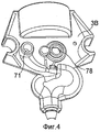
В предпочтительной конфигурации, устройство для дозирования и перемешивания согласно данному изобретению выполнено в виде чаши (крышки), которая присоединена к емкости с помощью подходящих средств соединения. Более конкретно, устройство для перемешивания включает две раковины-половинки, соединенные по линии разъема, проходящей через средства всасывания и насос. Конструкция в форме чаши с двумя раковинами-половинками обладает преимуществами, а именно, она требует меньшее количество соединяемых элементов и, кроме того, более компактна по сравнению с известными конструкциями, которые обычно содержат средства нагнетания и перемешивания.In a preferred configuration, the dispensing and mixing device according to this invention is made in the form of a bowl (lid), which is attached to the container using suitable means of connection. More specifically, the stirring device includes two half sinks connected along a connector line through suction means and a pump. The bowl-shaped design with two half-shells has advantages, namely, it requires fewer connected elements and, moreover, is more compact in comparison with the known designs, which usually contain means for pumping and mixing.
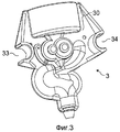
Одна или другая раковина-половинка или, в качестве альтернативы, обе раковины-половинки при их соединении по линии разъема образуют:One or the other half-shell or, alternatively, both half-shells when connected along the connector line form:
камеру насоса и ее канал для дозирования,pump chamber and its channel for dispensing,
средства всасывания, содержащие по меньшей мере одно сужение сечения,suction means containing at least one narrowing section,
канал для разбавителя,diluent channel
смесительную камеру,mixing chamber
воздушный канал, при желании, иair duct, if desired, and
предпочтительно, кроме того, канал для отпуска порции приготовленного продукта, например напитка.preferably, in addition, a channel for dispensing a portion of a prepared product, for example a beverage.
Устройство для дозирования и перемешивания при его выполнении из двух раковин-половинок, предпочтительно изготовлено из пластмассы, например, с помощью литья под давлением или формования пластмассы. Рассматриваемое устройство, таким образом, может быть использовано для осуществления ограниченного количества операций дозирования, после чего его удаляют или используют повторно.A device for dispensing and mixing when it is made of two half-shells, preferably made of plastic, for example, by injection molding or molding of plastic. The device in question can thus be used to carry out a limited number of dosing operations, after which it is removed or reused.
В соответствии с еще более предпочтительным воплощением устройство соединено с емкостью, образующей вместе с устройством для дозирования и перемешивания сменный блок, который может быть удален или использован повторно. Емкость может быть несжимаемым или сжимаемым элементом. При этом емкость может представлять собой, например, бутылку, контейнер в форме кирпича, пакет, саше (маленький пакетик) или тому подобное. Она может быть изготовлена из пластмассы, картона, бумаги, алюминия или смеси и/или ламината из этих материалов. Емкость и устройство могут быть соединены друг с другом неразъемно или с помощью средств разъема. Средствами неразъемного соединения могут быть пайка, сварка, использование связующего, необратимая фиксация и тому подобные средства. Средства, обеспечивающие разъем, могут означать сборку, образованную резьбовой частью или средствами эквивалентного взаимодополняющего механического соединения, имеющимися на чаше, образующей дозирующее устройство, которая взаимодействует с резьбовой частью или средствами взаимодополняющего механического соединения, принадлежащими емкости.According to an even more preferred embodiment, the device is connected to a container, which together with the metering and mixing device forms a replaceable unit, which can be removed or reused. The container may be an incompressible or compressible element. The container may be, for example, a bottle, a brick-shaped container, a bag, a sachet (small bag) or the like. It can be made of plastic, cardboard, paper, aluminum, or a mixture and / or laminate of these materials. The container and the device can be connected to each other inseparably or by means of a connector. The means of permanent connection can be soldering, welding, the use of a binder, irreversible fixation and the like. The means for providing the connector can mean an assembly formed by a threaded part or by means of an equivalent complementary mechanical connection available on a bowl forming a metering device that interacts with a threaded part or by means of an complementary mechanical connection belonging to the container.
Устройство для дозирования и перемешивания просто и быстро закрепляется на базовом агрегате. Для этого средства соединения, которыми снабжено устройство, предпочтительно расположены на одной и той же стороне с тем, чтобы обеспечить осуществление соединения посредством ручного подсоединения рассматриваемого устройства к стыковочной панели базового агрегата, который содержит взаимодополняющие (ответные) средства соединения. Таким образом, пользователь может легко осуществить операцию стыковки вручную путем простой манипуляции, взяв держатель дозирующего и перемешивающего устройства, на котором предпочтительно смонтирована емкость, и нажимая на него в направлении панели базового агрегата. В частности, средства соединения, кроме того, включают в себя средства для самонаведения при поступательном перемещении, по меньшей мере, в одном направлении, что способствует сочленению или стыковке дозирующего устройства, осуществляемому с помощью взаимодополняющих направляющих, которыми снабжена панель стыковки, имеющаяся в базовом агрегате. Очевидно, возможно использование и других способов стыковки, которые сочетают различные направления движения при сочленении, такие как направления с поступательным перемещением и с вращательным движением или перемещения в различных направлениях с сочетанием перемещений вдоль/вокруг различных осей поступательного движения и/или вращения.The device for dispensing and mixing is simply and quickly fixed to the base unit. For this, the means of connection provided with the device are preferably located on the same side so as to enable the connection by manually connecting the device in question to the docking panel of the base unit, which contains complementary (response) means of connection. Thus, the user can easily carry out the docking operation manually by simple manipulation, taking the holder of the metering and mixing device on which the container is preferably mounted and pushing it in the direction of the panel of the base unit. In particular, the means of connection, in addition, include means for homing during translational movement of at least one direction, which contributes to the articulation or joining of the metering device, carried out using complementary guides, which are provided with a docking panel, available in the base unit . Obviously, it is possible to use other docking methods that combine different directions of movement during articulation, such as directions with translational movement and with rotational movement or movements in different directions with a combination of movements along / around different axes of translational movement and / or rotation.
Устройство для дозирования и перемешивания в соответствии с изобретением, кроме того, может быть снабжено кодом, который может считываться считывателем, связанным с базовым агрегатом. Код содержит информацию, относящуюся к идентификации продукта и/или свойству продукта и/или к параметрам, связанным с включением подачи разбавителя и/или привода жидкостного насоса. Этот код, например, может быть использован для управления расходом насоса для жидкости и/или насоса для разбавителя, содержащихся в базовом агрегате, с тем, чтобы регулировать отношение расходов жидкости и разбавителя. Возможны и другие варианты использования кодов, такие, как проверка подлинность продукта, содержащегося в контейнере, или, в качестве альтернативы, регулирование определенных средств, служащих для изменения температуры разбавителя.The metering and stirring device according to the invention can also be provided with a code that can be read by a reader associated with the base unit. The code contains information related to the identification of the product and / or the property of the product and / or to the parameters associated with the inclusion of the supply of diluent and / or drive the liquid pump. This code, for example, can be used to control the flow rate of the liquid pump and / or diluent pump contained in the base unit in order to adjust the ratio of flow rates of liquid to diluent. Other uses for codes are possible, such as verifying the authenticity of the product contained in the container, or, alternatively, regulating certain means used to change the temperature of the diluent.
В соответствии с другим аспектом изобретение относится к блоку для дозирования жидкости и перемешивания этой жидкости с разбавителем с целью приготовления пищевого продукта, содержащему емкость, рассчитанную на большое количество порций, предназначенную для образования запаса жидкости, и устройство для дозирования и перемешивания, содержащее:In accordance with another aspect, the invention relates to a unit for dispensing a liquid and mixing this liquid with a diluent for the preparation of a food product, comprising a container designed for a large number of portions, designed to form a supply of liquid, and a device for dispensing and mixing, containing:
входное отверстие для разбавителя,diluent inlet
жидкостный насос для дозирования определенного количества жидкости,a liquid pump for dispensing a certain amount of liquid,
смесительную камеру для перемешивания жидкости и разбавителя,a mixing chamber for mixing the liquid and diluent,
средства соединения, сконфигурированные для подсоединения устройства для дозирования и перемешивания к базовому агрегату, который может обеспечивать подачу разбавителя и снабжен средствами привода насоса, нагнетающего концентрат, при этом устройство для дозирования и перемешивания образует присоединенную к емкости насадку в виде чаши.connection means configured to connect the dispensing and mixing device to the base unit, which can supply the diluent and is equipped with means for driving the concentrate pump, the dispensing and mixing device forming a nozzle attached to the container in the form of a bowl.
В настоящее время в уровне технике по существу отсутствуют сведения о каком-либо блоке, который обладает преимуществами, как с точки зрения гигиены, связанными с использованием дозирующего насоса, введенного в состав сменного блока, так и преимуществами, обусловленными простой и не дорогостоящей конструкцией, которая приспособлена для использования в течение ограниченного промежутка времени или может быть использован повторно. В то же время настоящее изобретение удовлетворяет всем этим качествам за счет обеспечения дозирующего устройства, выполненного, как правило, сборным и изготовленным из различных элементов, объединенных друг с другом с помощью соединительных элементов, так, что в результате оно принимает форму чаши, присоединенной к контейнеру в качестве укупорочного средства.Currently, in the prior art there is essentially no information about any unit that has advantages, both from the point of view of hygiene, associated with the use of a metering pump, which is included in the replaceable unit, and the advantages due to a simple and not expensive design, which adapted for use for a limited period of time or can be reused. At the same time, the present invention satisfies all these qualities by providing a metering device, made, as a rule, prefabricated and made of various elements combined with each other using connecting elements, so that as a result it takes the form of a bowl attached to the container as a closure.
В частности, эта чаша включает в себя две раковины-половинки, соединенные одна с другой вдоль продольной линии разъема и сконфигурированные с возможностью образования границ по меньшей мере контуров камеры насоса и смесительной камеры. Другими словами, эти два элемента соединены друг с другом вдоль линии разъема, проходящей в направлении, в котором транспортируются текучие среды, в частности, в том направлении, в котором транспортируются жидкость и смесь, состоящая из жидкости и разбавителя. В отличие от такого выполнения, известный аналог обычно обеспечивает наличие различных каналов и соединений, следующих один за другим в направлении, в котором транспортируются текучие среды, что приводит к большей сложности, быстрому загрязнению и проблемам гигиены, которые проявляются в большей степени из-за изменений поперечного сечения и применения большого количества элементов, и в результате стоимость изготовления также получается более высокой.In particular, this bowl includes two half-shells connected to each other along the longitudinal line of the connector and configured to form boundaries of at least the contours of the pump chamber and the mixing chamber. In other words, these two elements are connected to each other along the line of the connector extending in the direction in which the fluids are transported, in particular in the direction in which the liquid and the mixture consisting of liquid and diluent are transported. In contrast to this embodiment, the known analogue usually provides various channels and connections, one after the other in the direction in which the fluids are transported, which leads to greater complexity, rapid pollution and hygiene problems, which are manifested more due to changes cross-section and the use of a large number of elements, and as a result, the manufacturing cost is also higher.
В соответствии с данным изобретением канал для дозирования жидкости расположен так, что он пересекает канал для разбавителя перед смесительной камерой. Устройство для дозирования и перемешивания содержит, в дополнение к насосу для дозирования жидкости, средство для увеличения скорости, с которой разбавитель поступает в точку, где поток разбавителя встречается с потоком жидкости. Такое средство предпочтительно представляет собой сужение сечения канала, сообщающееся с входным отверстием для разбавителя, расположенным выше по ходу движения потока от смесительной камеры, и в результате поток разбавителя при прохождении сужения сечения канала ускоряется.In accordance with this invention, the channel for dispensing liquid is located so that it crosses the channel for the diluent in front of the mixing chamber. The metering and mixing device comprises, in addition to a liquid metering pump, means for increasing the rate at which the diluent enters the point where the diluent stream meets the liquid stream. Such a means is preferably a narrowing of the channel cross section communicating with a diluent inlet located upstream of the mixing chamber, and as a result, the diluent flow is accelerated when narrowing the channel cross section.
Вспенивание порции, например, напитка может быть получено, когда средства всасывания воздуха дополнительно представляют собой заборник воздуха (канал для впуска воздуха), который обеспечивает возможность подвода воздуха в смесь и вспенивания смеси жидкости и разбавителя, например, напитка, в смесительной камере. Однако при отсутствии необходимости во вспенивании порции продукта заборник воздуха может быть исключен или может избирательно перекрываться. Поперечное сечение заборника воздуха может быть различным в зависимости от свойств жидкого пищевого продукта, содержащегося в блоке. Так, поперечное сечение заборника воздуха может изменяться в интервале от 0,05 до 2 мм2, предпочтительно от 0,1 до 0,5 мм2.Foaming a portion of, for example, a beverage can be obtained when the air suction means further comprises an air intake (air inlet channel), which allows air to be introduced into the mixture and foaming of the liquid and diluent mixture, for example, the beverage, in the mixing chamber. However, in the absence of the need for foaming a portion of the product, the air intake may be eliminated or may selectively overlap. The cross section of the air intake may be different depending on the properties of the liquid food product contained in the block. Thus, the cross section of the air intake can vary in the range from 0.05 to 2 mm 2 , preferably from 0.1 to 0.5 mm 2 .
Жидкость может представлять собой пищевой концентрат, предназначенный для приготовления горячего или холодного, пенистого или не пенистого напитка. Например, жидкостью является концентрат на основе кофе, какао, молока, чая, фруктового сока или сочетание этих компонент. Концентратом может быть жидкость для производства, например, кофе с молоком, например, содержащее концентрат кофе и сгущенное молоко или молочный порошок. Вязкость жидкости может изменяться в соответствии со свойствами этого концентрата.The fluid may be a food concentrate for preparing hot or cold, foamy or non-foamy beverage. For example, the liquid is a concentrate based on coffee, cocoa, milk, tea, fruit juice, or a combination of these components. The concentrate can be a liquid for producing, for example, coffee with milk, for example, containing coffee concentrate and condensed milk or milk powder. The viscosity of the liquid may vary in accordance with the properties of this concentrate.
Как правило, вязкость находится в интервале от 1 до 5000 сантипуаз, предпочтительно от 200 до 1000 спз; однако, более предпочтительно от 300 до 600 спз.Typically, the viscosity is in the range from 1 to 5000 centipoise, preferably from 200 to 1000 cps; however, more preferably 300 to 600 cps.
Настоящее изобретение, наконец, относится к базовому агрегату, с которым, как отмечено выше, производится стыковка устройства для дозирования и перемешивания или упаковка.The present invention finally relates to a base unit, with which, as noted above, the device for dispensing and mixing is docked or packaged.
Базовый агрегат включает:The basic unit includes:
а) технический участок, содержащий средства подачи разбавителя, средства привода жидкостного насоса,a) a technical section containing means for supplying diluent, means for driving a liquid pump,
б) участок для стыковки, содержащий средства соединения, взаимодополняющие средства соединения, принадлежащие указанному устройству, сконфигурированные с возможностью стыковки устройства дозирования и перемешивания в предварительно заданном положении, а также средства соединения для подвода разбавителя, средства для подсоединения насоса и средства регулирования, предназначенные для регулирования подачи разбавителя и привода жидкостного насоса.b) a docking section, containing connecting means, complementary connecting means belonging to the specified device, configured to dock the dispensing and mixing device in a predetermined position, as well as connecting means for supplying diluent, means for connecting a pump and regulation means for regulating diluent feed and fluid pump drive.
Таким образом, предпочтительное воплощение агрегата содержит два отдельных участка, включая участок стыковки, доступный для потребителя. Этот участок может быть защищен с помощью защитных средств, например, кожуха или тому подобного средства, но это не является обязательным. Наоборот, часть этого участка может быть оставлена видимой, чтобы обеспечить более удобные ручные манипуляции для потребителя и облегчить выполнение операции замены упаковок.Thus, a preferred embodiment of the assembly comprises two separate sections, including a docking section, accessible to the consumer. This area may be protected by protective means, for example, a casing or the like, but this is not necessary. On the contrary, part of this section can be left visible to provide more convenient manual manipulations for the consumer and to facilitate the operation of replacing packages.
Более конкретно, средства подачи разбавителя включают канал для подачи разбавителя, соединенный с водяным насосом и с системой регулирования температуры воды. Система регулирования температуры может быть системой нагревания, например, термоблок, нагревательный резервуар, испаритель или другое эквивалентное средство. Система регулирования, кроме того, может быть системой охлаждения, способной производить охлажденные напитки или десерты.More specifically, the diluent supply means include a diluent supply passage connected to the water pump and to the water temperature control system. The temperature control system may be a heating system, for example, a fuser, a heating tank, an evaporator, or other equivalent means. The control system may also be a cooling system capable of producing chilled drinks or desserts.
Средства привода насоса могут включать в себя электрический двигатель и приводной вал, соединенный с взаимодополняющими средствами соединения, предназначенными для сочленения со средствами соединения, которыми снабжен жидкостный насос. Указанные средства соединения могут быть выполнены в виде элементов, образующих механическое соединение с прижатием друг к другу типа "мама-папа" (включающее охватывающий и охватываемый соединительные элементы), магнитный механизм, систему с резьбовым соединением или байонетным соединением или же они могут быть выполнены в виде каких-либо других эквивалентных средств.The pump drive means may include an electric motor and a drive shaft connected to complementary coupling means for coupling with the coupling means provided with the liquid pump. These means of connection can be made in the form of elements that form a mechanical connection with pressing to each other type of "mom-dad" (including female and male connectors), a magnetic mechanism, a system with a threaded connection or bayonet connection, or they can be made in in the form of any other equivalent means.
Участок стыковки содержит направляющие средства, взаимодополняющие направляющие средства, имеющиеся в устройстве для дозирования и перемешивания, предназначенные для пристыковки указанного устройства. Взаимодополняющие направляющие сконфигурированы таким образом, чтобы придать дозирующему устройству поступательное движение в процессе стыковки или придать ему перемещение в одном или более других направлениях. При этом могут быть использованы средства, обеспечивающие фиксацию дозирующего устройства в положении стыковки.The docking section contains guide means complementary to the guide means available in the metering and mixing device for docking said device. The complementary guides are configured so as to give the dosing device translational movement during the joining process or to give it movement in one or more other directions. In this case, means can be used to ensure the fixation of the metering device in the docking position.
Базовый агрегат содержит блок управления, взаимосвязанный со средствами управления и запрограммированный для регулирования и согласования включения привода жидкостного насоса и приведения в действие средств подачи разбавителя. Когда устройство для дозирования и перемешивания или сменный блок содержат код, блок управления взаимосвязан со считывателем, способным считывать этот код и обрабатывать считанную информацию.The base unit contains a control unit interconnected with the controls and programmed to regulate and coordinate the activation of the fluid pump drive and actuating the diluent supply means. When the metering and stirring device or plug-in unit contains a code, the control unit is interconnected with a reader capable of reading this code and processing the read information.
Особенности и преимущества настоящего изобретения будут более понятны из сопровождающих чертежей.Features and advantages of the present invention will be more apparent from the accompanying drawings.
Краткое описание чертежейBrief Description of the Drawings
Фиг.1 - общая перспектива аппарата, соответствующего настоящему изобретению, содержащего упаковку согласно изобретению, рассчитанную на большое количество порций, показанную в положении отдельно от базового агрегата.Figure 1 is a General perspective of the apparatus corresponding to the present invention, containing a package according to the invention, designed for a large number of portions, shown in position separately from the base unit.
Фиг.2 - общая перспектива аппарата, показанного на фиг.1, с упаковкой на большое количество порций, показанной состыкованной с базовьм агрегатом.Figure 2 is a General perspective of the apparatus shown in figure 1, with packaging for a large number of portions, shown docked with the base unit.
Фиг.3 - передняя раковина-половинка устройства для дозирования и перемешивания, соответствующего данному изобретению.Figure 3 - front sink-half of the device for dispensing and mixing, corresponding to this invention.
Фиг.4 - задняя раковина-половинка устройства для дозирования и перемешивания, соответствующего данному изобретению.Figure 4 - the rear shell-half of the device for dispensing and mixing, corresponding to this invention.
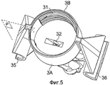
Фиг.5 - устройство, показанное на фиг.3 и фиг.4, вид сверху.Figure 5 - the device shown in figure 3 and figure 4, a top view.
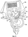
Фиг.6 - внутренняя часть передней раковины-половинки устройства, показанного на фиг.3 - фиг.5, без шестерен.6 - the inner part of the front shell half of the device shown in figure 3 - figure 5, without gears.
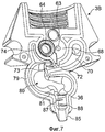
Фиг.7 - внутренняя часть задней раковины-половинки устройства, показанного на фиг.3-фиг.5.Fig.7 - the inner part of the rear shell half of the device shown in Fig.3-Fig.5.
Фиг.8 - насос устройства, показанного на фиг.3 - фиг.7, детальное изображение в частичном разрезе.Fig.8 is a pump of the device shown in Fig.3 - Fig.7, a detailed image in partial section.
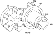
Фиг.9 - вращающиеся элементы (шестерни) насоса для дозирования жидкости, вид элементов в перспективе.Figure 9 - rotating elements (gears) of the pump for dispensing a liquid, a perspective view of the elements.
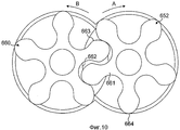
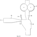
Фиг.10 - вращающиеся элементы в заданной конфигурации их сцепления, схематический вид спереди.Figure 10 - rotating elements in a given configuration of their clutch, a schematic front view.
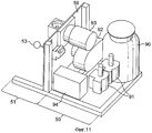
Фиг.11 - схематическое изображение элементов, входящих в состав базового агрегата.11 is a schematic illustration of the elements that make up the base unit.
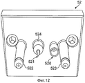
Фиг.12 - детальное изображение средств соединения, имеющихся в базовом агрегате.Fig - a detailed image of the means of connection available in the base unit.
Фиг.13 - схематическое изображение устройства согласно настоящему изобретению, соответствующее направлению движения в устройстве потоков различных текучих сред.13 is a schematic illustration of a device according to the present invention, corresponding to the direction of movement of various fluids in a device.
Фиг.14 - детальное изображение поперечного сечения примера выполнения устройства, соответствующего изобретению, в частности, изображение обратного клапана, который установлен на выходе насоса с целью предотвращения капания жидкости.Fig. 14 is a detailed cross-sectional view of an embodiment of a device according to the invention, in particular, an image of a check valve that is installed at the pump outlet to prevent dripping of liquid.
Подробное описание изобретенияDETAILED DESCRIPTION OF THE INVENTION
Фиг.1 и фиг.2 иллюстрируют общий вид одного примера воплощения аппарата для разбавления концентрата и раздачи порций пищевого продукта в соответствии с данным изобретением, в частности, аппарата 1 для приготовления горячих и холодных напитков.Figure 1 and figure 2 illustrate a General view of one example embodiment of an apparatus for diluting a concentrate and distributing portions of a food product in accordance with this invention, in particular, apparatus 1 for preparing hot and cold drinks.
Данный аппарат содержит по меньшей мере один сменный блок 2, состоящий из дозирующего и смесительного устройства 3 и емкости 4, с одной стороны, и базовый агрегат 5, с другой стороны, который служит для закрепления на нем сменного блока 2 с целью приготовления и раздачи напитков с помощью устройства 3 для дозирования и перемешивания. Устройство 3 присоединено к емкости 4, которая может быть любого вида, например, бутыль, емкость в форме брикета, саше (маленький пакетик), пакет или тому подобное. Емкость содержит жидкий пищевой продукт, предназначенный для его разбавления разбавителем, как правило, водой, например, горячей, находящейся при комнатной температуре или охлажденной, подводимой в дозирующее устройство 3 из базового агрегата 5. Жидкость может быть в виде концентрата кофе, молока, какао, фруктового сока или смеси, порция которой приготовлена, например, на основе концентрата кофе с включением эмульгатора, ароматической добавки, сахара или искусственного подсластителя, консервантов и других ингредиентов. Жидкость может содержать чисто жидкую фазу с возможными включениями твердых и пастообразных компонентов, например, частиц сахара, орехов, фруктов или тому подобного. Предпочтительно жидкость выбирают такой, чтобы она была стабильной при температуре окружающей среды в течение нескольких дней или даже нескольких месяцев. В результате ферментная активность концентрата в воде устанавливается на некотором уровне, который позволяет выдерживать концентрат при окружающей температуре в течение требуемого промежутка времени.This apparatus contains at least one
Устройство 3 для дозирования и перемешивания и емкость 4 предпочтительно выбраны такими, чтобы их можно было удалить или использованы повторно, сразу после освобождения емкости от ее содержимого. Емкость удерживают в опрокинутом положении, при этом ее выпускное отверстие направлено вниз, а днище обращено вверх, с тем, чтобы постоянно подавать жидкость под действием сил тяжести в устройство 3 для дозирования и перемешивания, в частности, в дозирующий насос, входящий в состав устройства. Емкость 4 и устройство 3 соединены с помощью средств соединения, которые могут быть разъемными или неразъемными, в зависимости от возможного реализуемого случая. Предпочтительно, однако, использовать средства неразъемного соединения, с тем, чтобы избежать использования устройства для дозирования и перемешивания в течение чересчур продолжительного периода времени, что, без проведения очистки после слишком продолжительного периода времени работы, может, в конце концов, создать проблемы в части гигиены. Дело в том, что неразъемное соединение вынуждает заменять весь сменный блок 2 целиком после опорожнения емкости, или даже до опорожнения, если устройство слишком долго остается неиспользованным и существует опасность проблем гигиены. Однако, внутренняя часть (внутренняя поверхность) устройства 3 спроектирована так, чтобы ее можно было очищать и/или промывать разбавителем при высокой температуре, например, регулярно, или, например, путем проведения циклов промывки, которые активируются по программе или вручную и управляются из базового агрегата 5.The metering and mixing
Фиг.3 - фиг.9 детально иллюстрируют предпочтительный пример осуществления устройства 3 для дозирования и перемешивания в соответствии с изобретением. Устройство 3 предпочтительно выполнено в виде чаши (крышки), которая герметично закрывает отверстие емкости, находящейся в опрокинутом положении, при котором ее отверстие обращено вниз. Указанная чаша имеет цилиндрическую соединительную часть 30, снабженную средствами соединения, например, внутренней резьбой 31, ответной средству соединения 41, принадлежащему емкости и представляющему собой, например, также определенный тип резьбы. Внутри соединительной части имеются торцевая поверхность и проходящее сквозь эту поверхность впускное отверстие 32, предназначенное для впуска жидкости в устройство. Следует отметить, что опрокинутое положение емкости оправдано только в том случае, если в емкости имеется отверстие, служащее для входа воздуха с целью выравнивания в емкости давления, и поэтому емкость не сжимается в объеме по мере ее опорожнения. В противном случае, например, в случае пакета, сжимающегося без притока в него воздуха, жидкость может дозироваться, когда емкость вместе с закрывающей ее чашей находится в каком-либо положении, которое не обязательно опрокинутое.Figure 3 - figure 9 illustrate in detail a preferred embodiment of the
Устройство 3, следует заметить, предпочтительно выполнено из двух раковин-половинок 3A, 3B, соединенных одна с другой по линии разъема Р, проходящей в направлении, более или менее совпадающем с продольным направлением имеющихся в устройстве каналов (в частности, канала для жидкости) и смесительной камеры. Такая конструкция в виде двух раковин-половинок, а именно, передней части 3A и другой, задней части 3B, позволяет упростить устройство, ив то же время образует определенную последовательность каналов и камер, необходимых для дозирования, перемешивания, возможного вспенивания и раздачи смеси.The
Когда емкость выполнена такой, что она не может сжиматься, в емкость необходимо обеспечить подвод воздуха для компенсации отвода жидкости. Такой подвод воздуха может быть обеспечен или непосредственно через емкость, например, через отверстие в днище емкости, находящейся в опрокинутом положении, или в качестве альтернативы, по меньшей мере через один воздушный канал, проходящий через цилиндрическую соединительную часть 30 устройства, которая сообщается с входом в емкость.When the container is made such that it cannot be compressed, it is necessary to provide air inlet to the tank to compensate for the removal of liquid. Such an air supply can be provided either directly through the container, for example, through an opening in the bottom of the container in the overturned position, or alternatively through at least one air channel passing through the cylindrical connecting
Далее будут подробно описаны основные элементы устройства 3 для дозирования и перемешивания. Указанное устройство содержит вмонтированный дозирующий насос 6 для дозирования жидкости, подводимой через отверстие 32. Насос предпочтительно представляет собой шестеренчатый насос, образованный камерой 60, снабженной подшипниковыми опорами 61, 61, 63, 64, находящимися в нижней части каждой из боковых поверхностей 67, 68 камеры и обеспечивающими придание определенной ориентации двум вращающимся элементам 65, 66, взаимодействующим при нахождении в зацеплении с образованием в камере подвижных дозирующих элементов насоса. Вращающийся элемент 65 является "ведущим" элементом, снабженным валом 650, совмещенным со средствами 651 соединения, приспособленными для соединения с ответными средствами соединения, принадлежащими базовому агрегату 5 (описаны ниже). Между подшипниковой опорой 64 и валом размещено манжетное уплотнение, служащее для уплотнения камеры насоса относительно окружающей среды. Внутреннее давление, созданное насосом при его функционировании, помогает поддерживать герметичность, оказывая нажимное (распирающее) воздействия на уплотнение. Вращающийся элемент 66 является "ведомым" элементом, приводимым во вращение в направлении, противоположном направлению вращения ведущего элемента. Вращающиеся дозирующие элементы 65, 66 приводятся во вращение в направлениях A, B, показанные на фиг.8 и фиг.10, с тем, чтобы обеспечивать дозирование жидкости через камеру. Конструкция в виде двух раковин-половинок такова, что камера образуется сборкой из двух частей 3A и 3B. Камера 60, таким образом, может быть образована в виде полости, находящейся в передней части 3А, с нижней поверхностью 67, образованной одной из боковых поверхностей. Другая часть 3В ограничивает камеру более или менее плоским участком 68 поверхности, например, содержащим подшипниковую опору 64, которая поддерживает приводной вал 650, выходящий наружу через отверстие 78, имеющееся в раковине-половинке 3В.Next, the basic elements of the metering and mixing
Жидкость в устройстве дозируется через выходной канал 69 для жидкости, имеющий сужение сечения. Диаметр в месте сужения составляет порядка от 0,2 до 4 мм, предпочтительно от 0,5 до 2 мм. Канал 69 обеспечивает точный контроль расхода жидкости, выходящей из насоса, и позволяет формировать относительно суженный поток жидкости, что способствует точному дозированию жидкости.The liquid in the device is dosed through the
Устройство 3 содержит канал 70 для подачи разбавителя, который пересекает канал 69 для жидкости. Разбавитель транспортируется в устройство через ввод 71, проходящий через заднюю часть 3B чаши. Этот ввод представляет собой соединительный патрубок, выполненный с возможностью соединения, осуществляемого по глухой посадке с уплотнением, с цилиндрическим соединительным элементом, служащим для подачи разбавителя, размещенным на базовом агрегате 5, при этом указанный соединительный патрубок вводится в цилиндрический соединительный элемент. Расход разбавителя регулируют с помощью насоса, подающего разбавитель, размещенного в базовом агрегате 5. Канал 70 для разбавителя заканчивается сужением 72 сечения, которое начинается более или менее выше по ходу движения потока от точки пересечения каналов 69, 70 для жидкости и разбавителя, и продолжается по меньшей мере до указанной точки пересечения каналов и предпочтительно за пределы этой точки. Упомянутое сужение сечения позволяет ускорить поток разбавителя, что, за счет реализации процесса, происходящего в трубке Вентури, приводит к тому, что давление в точке пересечения и слияния потоков становится ниже или равно давлению жидкости в выходном канале 69 для жидкости. Когда насос отключают, это равенство или разность давлений обеспечивает возможность пересечения разбавителем места дозирования жидкости и его прохождения вплоть до смесительной камеры без подъема обратно внутрь канала для жидкости. Несмотря на то, что жидкостный насос останавливается, разбавитель продолжает протекать через устройство, например, в направлении завершения цикла приготовления напитка, с тем, чтобы получить желательное разбавление напитка. Кроме того, этот разбавитель используют для регулярной промывки устройства. В результате предотвращается загрязнение жидкости, например, концентрата кофе или какао, находящейся в емкости или насосе, разбавителем, всасываемым обратно через канал 69.The
Сужение сечения характеризуется размером, необходимым для создания незначительного понижения давления в точке слияния потоков. Однако понижение давления необходимо регулировать таким образом, чтобы оно не было заметно ниже точки кипения и при приготовлении горячих напитков не приводило к вскипанию разбавителя в канале.The narrowing of the cross section is characterized by the size necessary to create a slight decrease in pressure at the point of confluence of the flows. However, the pressure drop must be adjusted so that it is not noticeably lower than the boiling point and during the preparation of hot drinks does not lead to boiling of the diluent in the channel.
Предпочтительно, диаметр сужения составляет от 0,2 до 5 мм, более предпочтительно от 0,5 до 2 мм.Preferably, the narrowing diameter is from 0.2 to 5 mm, more preferably from 0.5 to 2 mm.
После точки слияния потоков обе текучие среды транспортируются через один и тот же канал 73. Расширение этого канала предпочтительно рассчитано на снижение перепада давления и учитывает увеличение объема текучих сред, которые объединяются при их пересечении в точке слияния потоков. Расширенный канал 73 проходит собственно в смесительную камеру 80, в которой продукт равномерно перемешивается.After the confluence point of the flows, both fluids are transported through the
Конечно, при отсутствии необходимости резкого изменения (сечения) участок 73 канала и камера 80 могут образовать один и такой же канал или одну и такую же камеру.Of course, in the absence of the need for a drastic change (section), the
Заборник воздуха, представляющий собой воздушный канал 73, сообщающийся с окружающим воздухом, предпочтительно обеспечивается в устройстве в том случае, когда желательно вспенивание смеси жидкости и разбавителя. Предпочтительно, воздушный канал может быть расположен так, чтобы он пересекался с местом сужения сечения канала. Именно в этом месте реализуется эффект Вентури и, следовательно, происходит снижение давления до максимальной величины вследствие ускорения текучих сред. Воздушный канал может быть расположен, например, так, чтобы он пересекал участок 73 канала. Расположение заборника воздуха может меняться и может быть спланировано так, чтобы он проходил к каналу 70 для разбавителя или, в качестве альтернативы, к каналу 69 для жидкости. Таким образом, предпочтительно, чтобы заборник воздуха был расположен таким образом, чтобы воздух всасывался в него под воздействием потока разбавителя, проходящего с ускорением через место сужения канала.An air intake, which is an
В соответствии с возможным вариантом исполнения (не иллюстрируется) к заборнику воздуха может быть подсоединен воздушный насос. Этот воздушный насос (нагнетатель воздуха) может быть использован для создания избыточного давления в заборнике воздуха, которое вынуждает воздух смешиваться с потоком разбавителя. Обычно, сужение канала для разбавителя является подходящим для всасывания достаточного количества воздуха с целью создания пузырьков в смеси, но, как установлено, воздушный насос может быть полезным, в частности, при повышенных температурах разбавителя, когда в устройстве может начинаться формирование водяного пара, что в результате приводит к недостаточности условий для всасывания воздуха. Воздушный насос может быть также использован, чтобы подавать воздух в смесительную камеру в конце цикла раздачи напитка, для того, чтобы опорожнить камеру от смеси и/или чтобы высушить смесительную камеру в целях соблюдения гигиены. Заборник воздуха, кроме того, должен сообщаться с атмосферным давлением в конце цикла раздачи напитка, чтобы обеспечить опорожнение смесительной камеры надлежащим образом. Необходимое превышение атмосферного давления может быть достигнуто с помощью действующего клапана, размещенного в системе подачи воздуха в более высокой точке.According to a possible embodiment (not illustrated), an air pump may be connected to the air intake. This air pump (air blower) can be used to create excess pressure in the air intake, which forces the air to mix with the diluent stream. Typically, the narrowing of the diluent duct is suitable for sucking in enough air to create bubbles in the mixture, but it has been found that an air pump can be useful, in particular, at elevated diluent temperatures, when water vapor formation can begin in the device, which the result is insufficient conditions for air intake. An air pump may also be used to supply air to the mixing chamber at the end of the beverage dispensing cycle, in order to empty the chamber from the mixture and / or to dry the mixing chamber in order to maintain hygiene. The air intake must also communicate with atmospheric pressure at the end of the beverage dispensing cycle to ensure that the mixing chamber is properly emptied. The necessary excess of atmospheric pressure can be achieved by using an operating valve located in the air supply system at a higher point.
Смесительная камера 80 имеет ширину порядка по меньшей мере в пять раз, предпочтительно, по меньшей мере, в десять или двадцать раз больше поперечного сечения участка 73 канала, более или менее на выходе из точки слияния потоков. Широкая камера предпочтительна обычному каналу, поскольку она способствует перемешиванию и, кроме того, предотвращает всасывание какого-либо количества жидкости обратно в систему с трубкой Вентури, когда устройство не используется, поскольку это препятствует поддержанию хорошей гигиены в устройстве. Однако, в принципе, камера может быть заменена каналом меньшего поперечного сечения.The mixing
Кроме того, камера позволяет замедлить скорость течения смеси, и, следовательно, позволяет избежать чересчур быстрого ее вытеснения и, возможно, из-за этого с разбрызгиванием, при выпуске из устройства. По этой причине, камера предпочтительно имеет искривленный профиль, или даже предпочтительно имеет S-образный профиль с тем, чтобы удлинить путь движения смеси и уменьшить скорость ее движения.In addition, the camera allows you to slow down the flow rate of the mixture, and, therefore, allows you to avoid its too rapid displacement and, possibly, due to this with spraying, when released from the device. For this reason, the chamber preferably has a curved profile, or even preferably has an S-shaped profile in order to lengthen the path of movement of the mixture and reduce the speed of its movement.
Камера преимущественно подсоединена к выпускному каналу 85 для отвода смеси. Кроме того, в целях полного опорожнения, после каждого цикла отпуска напитка, камеры, имеющей искривленную форму, может быть использован сифонный канал 81.The camera is mainly connected to the
Сифонный канал предпочтительно содержит элементы 86, 87, 88 для резкого снижения кинетической энергии потока смеси в таком канале. Этими элементами, например, могут быть несколько перегородок, проходящих в поперечном направлении относительно канала, частично пересекающих поток смеси и вынуждающих этот поток следовать по извилистой траектории. Кроме того, эти элементы предназначены для гомогенизации смеси перед ее выпуском. Конечно, и возможны другие типы элементов, используемых для возмущения потока налитка.The siphon channel preferably contains
Устройство для дозирования и перемешивания в соответствии с настоящим изобретением, кроме того, предпочтительно содержит направляющие, обеспечивающие стыковку устройства с базовым агрегатом и, в частности, облегчающие сочленение средств соединения, используемых для подвода разбавителя и привода насоса. Этими направляющими, например, могут быть участки поверхностей 33, 34, 35, 36, проходящих через устройство, например, в поперечном направлении относительно частей 3A и 3B. Эти поверхности, например, могут быть образованы частично или полностью цилиндрическими участками. Кроме того, указанные направляющие выполняют функцию поддерживания веса сменного блока и обеспечивают прочную и устойчивую стыковку. Эти средства, конечно, могут принимать другие в значительной степени изменяемые формы воплощения.The dispensing and stirring device according to the present invention further preferably comprises guides for coupling the device to the base unit and, in particular, for facilitating articulation of the coupling means used to supply the diluent and drive the pump. These guides, for example, can be sections of
Части 3A и 3B соединяют друг с другом какими-либо подходящими методами, например, сваркой, пайкой или тому подобным методом. В предпочтительном воплощении эти две части соединяют с помощью лазерной сварки. Лазерная сварка может проводиться с компьютерным управлением процесса сварки и имеет преимущество сваривания частей вместе без какого-либо их относительного движения, в отличие от вибрационной сварки. Это улучшает соответствие допускам на размеры и точность сварки. Для лазерной сварки одна из свариваемых частей может быть изготовлена из материала, который больше поглощает энергию лазерного излучения, в то время как другая часть может быть изготовлена из пластмассы, прозрачной для энергии лазерного излучения. Однако, возможны и другие методы сварки без выхода за пределы объема настоящего изобретения, например, та же вибрационная сварка.
Предпочтительно обеспечить соединительный стык 79, например, как место сварки, который частично или полностью окаймляет каналы и камеры устройства. Этот стык предпочтительно идеально герметизирован. Однако стык может быть выполнен с не сваренными участками, служащими для регулирования входа воздуха в устройство.It is preferable to provide a connecting joint 79, for example, as a welding spot, which partially or completely borders the channels and chambers of the device. This joint is preferably perfectly sealed. However, the joint can be made with not welded sections that serve to regulate the entry of air into the device.
На фиг.9 и фиг.10 представлено подробное изображение вращающихся элементов 65, 66 жидкостного насоса. В имеющей преимущество конструкции каждый из элементов 652, 660 зубчатого зацепления имеет взаимно дополняющий профиль, поперечное сечение которого имеет скругленную форму в направлении концов с зоной 661 суженного поперечного сечения, находящейся у основания каждого из зубьев. Такая геометрия скругленного зуба позволяет создать замкнутую область 662 объемного дозирования, которая не подвергается сжатию и переносит объем жидкости, который является постоянным для каждого оборота вращения. Указанная конфигурация вращающихся элементов обуславливает уменьшение воздействия, направленного на сжатие дозируемой жидкости, что улучшает эффективность работы насоса и уменьшает действующие на насос нагрузки. Наиболее удаленный участок 662 каждого зуба, в предпочтительном исполнении, сплюснут и имеет радиус больший радиуса боковых сторон 663 каждого зуба. Сплющивание наиболее крайних участков 664, в частности, приближает зуб к поверхности камеры насоса, в результате чего уменьшается зазор и улучшается герметичность.Figure 9 and figure 10 presents a detailed image of the
Устройство может содержать несколько насосов для жидкости, каждый из которых содержит канал для жидкости, объединяющийся с каналом для разбавителя. Преимущество, таким образом, заключается в возможности перемешивания нескольких различных жидкостей с различными отношениями расходов, определяемых каждым из насосов. Насосы могут быть расположены как в одной и той же плоскости, так в параллельных плоскостях. Емкость может содержать несколько отсеков с различными жидкостями, при этом каждый отсек сообщается с соответствующим ему насосом. Таким образом, порция напитка может включать два компонента, которые должны содержаться отдельно в целях стабильности, сохранности, или же выгодно, например, основу из концентрата, с одной стороны, и ароматизирующую добавку, с другой стороны, дозировать, таким образом, различными насосами для воспроизводства ароматизированного напитка или напитка с более приятным вкусом. Кроме того, можно обеспечить отдельный канал для разбавителя на каждый из каналов для жидкости.The device may include several pumps for liquid, each of which contains a channel for liquid, combined with a channel for diluent. The advantage, therefore, is the possibility of mixing several different liquids with different flow ratios determined by each of the pumps. Pumps can be located both in the same plane and in parallel planes. A container may contain several compartments with different liquids, with each compartment communicating with its corresponding pump. Thus, a serving of a drink can include two components that must be separately kept for stability, preservation, or it is advantageous, for example, to use a base from a concentrate, on the one hand, and a flavoring agent, on the other hand, to dispense, thus, with different pumps for the reproduction of a flavored beverage or a drink with a more pleasant taste. In addition, it is possible to provide a separate diluent channel for each of the liquid channels.
Необходимо отметить, что данное устройство может дозировать жидкости в широком диапазоне величин вязкости. Однако, если жидкость слишком текучая, то может быть необходимым снабдить канал 69 для дозирования жидкости или входное отверстие 32 клапаном с тем, чтобы предотвратить опасность утечек жидкости. Этот клапан конструктивно выполнен так, что он открывается под давлением жидкости, создаваемым насосом, и остается закрытым и герметичным при отключении насоса, с тем, чтобы предотвратить протекание через устройство какого-либо количества жидкости.It should be noted that this device can dispense liquids in a wide range of viscosity values. However, if the fluid is too fluid, it may be necessary to provide a
Необходимо также отметить, что может потребоваться, чтобы давление внутри емкости, если она специально не спроектирована сжимаемой, было выровнено с давлением окружающей среды с помощью средств подвода воздуха. Если емкость выполнена без подвода воздуха, она может быть сжата вследствие снижения давления внутри емкости, и поэтому она может разрушиться. Средством подвода воздуха может быть клапан, например, клапан типа "утиный нос" (с плоским концом и щелевым отверстием) и тому подобный клапан. Другой путь подвода воздуха в емкость может заключаться в приведении в действие насоса с реализацией нескольких оборотов в направлении вращения, противоположном направлению вращения при дозировании напитка.It should also be noted that it may be necessary that the pressure inside the tank, if it is not specifically designed to be compressible, be aligned with the ambient pressure using air supply means. If the container is made without air supply, it can be compressed due to a decrease in pressure inside the container, and therefore it can be destroyed. The air supply means may be a valve, for example, a duck-nose valve (with a flat end and a slotted hole) and the like. Another way of supplying air to the container may be to actuate the pump with the implementation of several revolutions in the direction of rotation opposite to the direction of rotation when dispensing the drink.
Аппарат, соответствующий настоящему изобретению, представленный на фиг.1-2, 11 и 12, содержит также базовый агрегат 5, образующий машинную (с механизмами и силовыми приводами) часть аппарата, в отличие от сменного блока 2. Базовый агрегат включает техническую зону 50, в основном, размещенную внутри агрегата и защищенную, по меньшей мере, частично, с помощью кожуха 55, и зону 51 стыковки, непосредственно доступную для пользователя. Зона стыковки, кроме того, снабжена средствами 53 управления процессом отпуска напитка. Указанные средства управления могут быть выполнены в виде панели электронного управления (см. фиг1 и фиг.2) или рычаговой рукоятки (фиг.11).The apparatus corresponding to the present invention, shown in figures 1-2, 11 and 12, also contains a
Зона 51 стыковки выполнена таким образом, что она обеспечивает стыковку по меньшей мере одной упаковки 2, по меньшей мере, посредством, по меньшей мере, одной позиции 52 стыковки. Может быть использовано несколько позиций для стыковки, установленных последовательно в ряд, каждая для подсоединения сменного блока, при этом присоединяемые блоки содержат различные или одинаковые жидкие пищевые продукты, что обеспечивает возможность предложения разнообразного выбора напитков или, в качестве альтернативы, увеличение функциональных возможностей аппарата. Как показано на фиг.12, позиция стыковки снабжена средствами 520 подключения подачи разбавителя и средствами для подсоединения привода дозирующего насоса 521. Средства 520 могут быть выполнены в виде отрезка трубки, к которому прикреплен обратный клапан, при этом диаметр указанного отрезка трубы согласуется с диаметром входного отверстия 71 для разбавителя, имеющегося в устройстве для дозирования перемешивания, таким образом, чтобы счет этого согласования обеспечивать их соединение. Сборка может быть осуществлена с использованием одного или большего количества уплотнений. Средства 521 соединения представляют собой, например, участок вала, оканчивающийся оголовком меньшего поперечного сечения, имеющий поверхности, которые являются взаимодополняющими для внутренних поверхностей средств 651 соединения, принадлежащих устройству для дозирования и перемешивания. Оголовок может иметь заостренный профиль с сечением в виде многогранника или может, например, иметь профиль в виде звезды, что предполагает как скорость сочленения, так и надежность привода вращения насоса. Позиция стыковки, кроме того, может содержать направляющие 522, 523, которые являются взаимодополняющими (ответными) для направляющих 33, 34 устройства для дозирования и перемешивания. Эти направляющие 522, 523, для их согласования с поверхностями направляющих 33, 34 при их взаимном скольжении, могут представлять собой обычные стержни или пальцы. Понятно, что профиль направляющих 522, 523, 33, 34 может принимать различные формы без выхода за пределы объема изобретения. Например, направляющие 522, 523 позиции стыковки могут иметь полые профили с выемками, а направляющие 33, 34 устройства для дозирования и перемешивания могут быть выполнены с выступами.The
Базовый агрегат, как показано на фиг.11, имеет техническую зону, которая содержит совокупность элементов, существенных для снабжения разбавителем устройства 3 для дозирования и перемешивания, и для привода жидкостного насоса. В частности, базовый агрегат содержит источник подачи разбавителя, например, емкость с питьевой водой 90, подключенную к системе 91 нагнетания воды. Вода затем транспортируется по трубопроводам (не отображены) к системе 92 регулирования температуры воды. Такая система может быть системой нагревания и/или системой охлаждения, обеспечивающей повышение или понижение температуры до требуемой величины прежде, чем она поступит в устройство 3 для дозирования и перемешивания. Помимо того, базовый агрегат снабжен электрическим двигателем 93, управляемым посредством блока управления 94. Электрический двигатель 93 снабжен приводным валом 524, который проходит через панель 58 стыковки.The basic unit, as shown in Fig. 11, has a technical area, which contains a set of elements essential for supplying a diluent to the
Предпочтительно, чтобы аппарат в соответствии с настоящим изобретением обеспечивал возможность изменения количества дозируемой жидкости, в соответствии с требованиями, что осуществляется с помощью панели 53 управления, показанной расположенной в зоне стыковки, за счет выбора кнопок, каждая из которых запускает программу отпуска определенных напитков. В частности, соотношение "жидкость: разбавитель" можно менять путем изменения скорости вращения привода жидкостного насоса. Когда скорость вращения привода жидкостного насоса понижается, и при этом расход разбавителя сохраняют постоянным с помощью системы 91, включающей в себя насос для разбавителя, соотношение "жидкость: разбавитель" в результате уменьшается, что приводит к отпуску более разбавленного напитка. Наоборот, в случае повышения скорости вращения жидкостного насоса концентрация напитка может быть увеличена. Другим регулируемым параметром может быть объем напитка, который регулируют за счет изменения периода времени, в течение которого включена система с насосом для разбавителя, и периода времени, в течение которого приведен в действие жидкостный насос. Таким образом, блок управления 94 содержит все необходимые программы по приготовлению выбранных напитков, запускаемые посредством нажатия каждой из кнопок панели 53 управления.Preferably, the apparatus in accordance with the present invention provides the ability to change the amount of dosed liquid, in accordance with the requirements, which is carried out using the
Устройство 3 для дозирования и перемешивания или емкость также может содержать код, который может быть считан считывателем, подсоединенным к базовому агрегату 5. Этот код содержит информацию, относящуюся к идентификации и/или свойствам продукта и/или к параметрам, относящимся к включению подачи разбавителя и/или средств привода жидкостного насоса. Код может быть использован, например, для управления расходом насоса для жидкости и/или насоса для разбавителя, смонтированного в базовом агрегате, с тем, чтобы регулировать соотношение "жидкость: разбавитель". С помощью кода, кроме того, можно регулировать открытие или закрытие заборника воздуха для того, чтобы получить пенистый или не пенистый напиток.The metering and mixing
Как показано на фиг.13, воздушный заборник воздуха, или канал 74, может проходить с пересечением канала 70 для подачи разбавителя. Следовательно, он расположен перед местом пересечения потока жидкости и потока разбавителя. Проблема, связанная с размещением воздушного канала после точки пересечения каналов для подвода жидкости и разбавителя заключается в том, что воздушный канал может загрязняться разбавленной жидкостью, что может привести к размножению бактерий. Эта проблема в наибольшей степени связана с геометрическими и физическими свойствами, такими, как поверхностное натяжение жидкости, фазовые превращения и т.п. Воздушный канал в течение цикла промывки струей очищающей жидкости (например, горячей водой) не может быть очищен надлежащим образом, поскольку сужение сечения приводит к эффекту всасывания из воздушного канала в камеру перемешивания, что предотвращает поступление очищающей жидкости в воздушный канал. Следовательно, предложенное новое расположение воздушного канала не позволяет жидкому пищевому продукту поступать в воздушный канал. В настоящем примере канал 70 для разбавителя и канал 69 для дозирования жидкости не расположены непосредственно на пересечении одного канала с другим, а пересекаются со смесительной камерой 80. Однако, канал 70 для разбавителя расположен таким образом, что поток разбавителя, выходящий из канала, направлен в сторону потока жидкости, т.е. в направлении выхода жидкости или немного ниже по потоку жидкости. Помимо того, в зоне сужения 72 сечения канала 70 расположен выход заборника воздуха 74. Скорость течения разбавителя в зоне сужения такова, что воздух всасывается в поток разбавителя перед пересечением и слиянием этого потока с потоком жидкости. Такое решение снижает опасность загрязнения заборника воздуха разбавленным продуктом, поступающим в заборник воздуха в непредвиденном случае.As shown in FIG. 13, the air intake, or
В примере воплощения, иллюстрируемом на фиг.14, рассматриваемое устройство содержит обратный клапан для дозирования жидкости. Действительно, так как практически невозможно гарантировать полную герметичность, в особенности, в случае маловязких жидкостей, в канале для дозирования жидкости, ниже по потоку от насоса, устанавливают клапан 690. Поскольку из зоны 72 пересечения каналов и камеры смешения незначительные количества воды не могут быть удалены, то, если в эти зоны из насоса капает жидкость, разбавитель может загрязнять жидкость, что в результате после нескольких часов бездействия устройства создает потенциально благоприятную почву для размножения бактерий. Указанный клапан позволяет решить эту проблему за счет остановки капания жидкости в период бездействия устройства. В качестве такого клапана может быть использован обратный клапан любого типа. Клапан, показанный на фиг.14, содержит элемент клапана или слой 691, имеющий прорезь и выполненный из эластомера или силикона, который удерживается в канале 69 для жидкости, в положении поперек этого канала, с помощью двух жестких слоев, например, двух металлических пластин 692, 693. Клапан 690 может быть вставлен через щели, проходящие через две раковины-половинки 3A, 3B. Элемент клапана с прорезью выполнен так, что прорези открываются в направлении вниз по потоку, когда давление текучей среды в камере 60 насоса создано выше по потоку от клапана в результате приведения насоса в действие (элементы насоса не показаны). Как только насос останавливается, клапан, являясь достаточно упругим, перекрывает выход текучей среды.In the example embodiment illustrated in FIG. 14, the device in question comprises a check valve for dispensing a liquid. Indeed, since it is practically impossible to guarantee complete tightness, especially in the case of low-viscosity liquids, a
Настоящее изобретение, кроме того, распространяется на область приготовления не пищевых продуктов. Например, изобретение может быть использовано в области отпуска продуктов, которые поступают в виде жидкостей и которые могут быть разбавлены для отпуска, например, стиральные порошки, мыло, моющие средства или другие подобные продукты.The present invention also extends to the field of non-food preparation. For example, the invention can be used in the field of dispensing products that come in the form of liquids and which can be diluted for dispensing, for example, laundry detergents, soap, detergents or other similar products.
Claims (31)
канал (69) для дозирования жидкости,
впускное отверстие (71) для разбавителя с каналом (70) для разбавителя,
смесительную камеру (80) для перемешивания жидкости и разбавителя,
при этом канал (70) для разбавителя расположен относительно канала (69) для дозирования жидкости так, чтобы поток разбавителя пересекал поток жидкости перед смесительной камерой (80) или в смесительной камере, отличающееся тем, что оно снабжено жидкостным насосом (6), который является элементом устройства и предназначен для дозирования жидкости в канал для дозирования жидкости, а также оно содержит средства для повышения скорости потока разбавителя относительно его скорости во впускном отверстии (71) на том участке, где пересекаются потоки разбавителя и жидкости.1. A device (3) for dispensing a basic liquid and mixing this basic liquid with a diluent for preparing a non-food product, adapted to be connected to a container (4) containing a liquid, the device (3) comprising:
a channel (69) for dispensing a liquid,
inlet (71) for diluent with a channel (70) for diluent,
a mixing chamber (80) for mixing the liquid and diluent,
wherein the diluent channel (70) is located relative to the liquid dosing channel (69) so that the diluent stream crosses the liquid stream in front of the mixing chamber (80) or in the mixing chamber, characterized in that it is equipped with a liquid pump (6), which is element of the device and is designed to dispense liquid into the channel for dispensing liquid, and it also contains means to increase the flow rate of the diluent relative to its speed in the inlet (71) in the area where the flows intersect times diluent and liquid.
a) технический участок (50), содержащий средства (90, 91, 92) для подачи разбавителя и средства (93, 524) для привода жидкостного насоса,
b) участок стыковки (51) для пользователя, снабженный средствами соединения (520, 521, 522, 523), взаимодополняющими средства соединения (71, 651, 33, 34), принадлежащие устройству для дозирования и перемешивания, которые сконфигурированы для пристыковки указанного устройства для дозирования и перемешивания в заданном положении и которые включают средства (71) соединения для подвода разбавителя и средства (651) для подсоединения насоса, а также средства (53) регулирования, предназначенные для регулирования и подачи разбавителя и привода жидкостного насоса (6).17. The base unit (5), on which the device (3) for dispensing and mixing, designed for docking, is installed, corresponding to any one of claims 1-16, characterized in that it includes:
a) a technical section (50) containing means (90, 91, 92) for supplying diluent and means (93, 524) for driving a liquid pump,
b) a docking section (51) for the user, equipped with connecting means (520, 521, 522, 523), complementary connecting means (71, 651, 33, 34) belonging to the metering and mixing device, which are configured to dock the specified device for dosing and mixing in a predetermined position and which include means (71) for connecting a diluent and means (651) for connecting a pump, and also means (53) for regulating and supplying diluent and drive a liquid pump ( 6).
емкость (4), рассчитанную на большое количество порций продукта, предназначенную для создания запаса продукта;
устройство (3) для дозирования и перемешивания, выполненное согласно пп.1-16, с возможностью присоединения его с емкостью (4), при этом устройство (3) содержит впускное отверстие для разбавителя, жидкостный насос (6) для дозирования определенного количества жидкости, смесительную камеру (80) для перемешивания жидкости и разбавителя, средства соединения (71) для подвода разбавителя и средства привода (650, 651) насоса, которые сконфигурированы для присоединения устройства (3) для дозирования и перемешивания к базовому агрегату (5), способному обеспечить подачу разбавителя и имеющему средства (93, 524) для привода жидкостного насоса, отличающийся тем, что устройство (3) для дозирования и перемешивания имеет форму чаши, присоединенной к емкости (4).24. A replaceable unit (2) for dispensing a liquid and mixing this liquid with a diluent for preparing a non-food product, comprising:
capacity (4), designed for a large number of servings of the product, designed to create a stock of the product;
a device (3) for dispensing and mixing, made according to claims 1-16, with the possibility of attaching it to a container (4), the device (3) comprising an inlet for a diluent, a liquid pump (6) for dispensing a certain amount of liquid, a mixing chamber (80) for mixing the liquid and diluent, means of connection (71) for supplying diluent and means of drive (650, 651) of the pump, which are configured to connect the device (3) for dispensing and mixing to the base unit (5), capable of providing feeding a diluent and having means (93, 524) for driving a liquid pump, characterized in that the device (3) for dispensing and mixing has the shape of a bowl attached to the tank (4).
Applications Claiming Priority (2)
| Application Number | Priority Date | Filing Date | Title |
|---|---|---|---|
| EP04016210.9 | 2004-07-09 | ||
| EP04016210 | 2004-07-09 |
Related Parent Applications (1)
| Application Number | Title | Priority Date | Filing Date |
|---|---|---|---|
| RU2007104930A Division RU2376241C2 (en) | 2004-07-09 | 2005-06-13 | Apparatus and device intended for preparation and distribution of food products in form of mixture produced from liquid food product and thinner |
Publications (2)
| Publication Number | Publication Date |
|---|---|
| RU2009129940A RU2009129940A (en) | 2011-02-20 |
| RU2502666C2 true RU2502666C2 (en) | 2013-12-27 |
Family
ID=34925685
Family Applications (2)
| Application Number | Title | Priority Date | Filing Date |
|---|---|---|---|
| RU2007104930A RU2376241C2 (en) | 2004-07-09 | 2005-06-13 | Apparatus and device intended for preparation and distribution of food products in form of mixture produced from liquid food product and thinner |
| RU2009129940/12A RU2502666C2 (en) | 2004-07-09 | 2005-06-13 | Device and apparatus for preparation and dispensing of mixed products composed of main fluid and diluent |
Family Applications Before (1)
| Application Number | Title | Priority Date | Filing Date |
|---|---|---|---|
| RU2007104930A RU2376241C2 (en) | 2004-07-09 | 2005-06-13 | Apparatus and device intended for preparation and distribution of food products in form of mixture produced from liquid food product and thinner |
Country Status (19)
| Country | Link |
|---|---|
| US (3) | US8511516B2 (en) |
| EP (2) | EP1768925B1 (en) |
| JP (2) | JP5065893B2 (en) |
| KR (1) | KR20070042144A (en) |
| CN (2) | CN101786589B (en) |
| AT (1) | ATE477210T1 (en) |
| AU (1) | AU2005262036B2 (en) |
| BR (1) | BRPI0513193B1 (en) |
| CA (1) | CA2570288C (en) |
| DE (1) | DE602005022875D1 (en) |
| ES (2) | ES2348020T3 (en) |
| HK (2) | HK1105189A1 (en) |
| MX (1) | MX2007000321A (en) |
| MY (2) | MY143805A (en) |
| NZ (1) | NZ551598A (en) |
| PE (1) | PE20060217A1 (en) |
| RU (2) | RU2376241C2 (en) |
| TW (1) | TW200619127A (en) |
| WO (1) | WO2006005401A2 (en) |
Families Citing this family (96)
| Publication number | Priority date | Publication date | Assignee | Title |
|---|---|---|---|---|
| DE502005004144D1 (en) * | 2005-12-22 | 2008-06-26 | Wmf Wuerttemberg Metallwaren | Device for heating a liquid with steam |
| EP1806314A1 (en) * | 2006-01-09 | 2007-07-11 | Nestec S.A. | Device for dispensing a beverage with a controlled air inlet, and method therefor |
| US7757896B2 (en) | 2006-03-06 | 2010-07-20 | The Coca-Cola Company | Beverage dispensing system |
| US8960500B2 (en) * | 2006-03-06 | 2015-02-24 | The Coca-Cola Company | Dispenser for beverages including juices |
| US7913879B2 (en) | 2006-03-06 | 2011-03-29 | The Coca-Cola Company | Beverage dispensing system |
| US9415992B2 (en) | 2006-03-06 | 2016-08-16 | The Coca-Cola Company | Dispenser for beverages having a rotary micro-ingredient combination chamber |
| US9821992B2 (en) | 2006-03-06 | 2017-11-21 | The Coca-Cola Company | Juice dispensing system |
| US10631558B2 (en) | 2006-03-06 | 2020-04-28 | The Coca-Cola Company | Methods and apparatuses for making compositions comprising an acid and an acid degradable component and/or compositions comprising a plurality of selectable components |
| US10280060B2 (en) | 2006-03-06 | 2019-05-07 | The Coca-Cola Company | Dispenser for beverages having an ingredient mixing module |
| US8739840B2 (en) | 2010-04-26 | 2014-06-03 | The Coca-Cola Company | Method for managing orders and dispensing beverages |
| NL1032080C2 (en) * | 2006-04-19 | 2007-10-22 | Sara Lee De Nv | Interchangeable holder for use in an apparatus for preparing a drink suitable for consumption. |
| NL1032085C2 (en) | 2006-04-19 | 2007-10-22 | Sara Lee De Nv | System for preparing a drink suitable for consumption, as well as exchangeable holder for such a system and method for manufacturing the exchangeable holder. |
| NL1032090C2 (en) * | 2006-04-19 | 2007-10-22 | Sara Lee De Nv | System for preparing a predetermined amount of beverage suitable for consumption, exchangeable container and an apparatus for use in such a system. |
| NL1032091C2 (en) | 2006-04-19 | 2007-10-22 | Sara Lee De Nv | System for preparing a drink suitable for consumption, as well as an exchangeable holder for such a system. |
| NL1032087C2 (en) | 2006-04-19 | 2007-10-22 | Sara Lee De Nv | Beverage preparation system, container and device. |
| NL1032082C2 (en) * | 2006-04-19 | 2007-10-22 | Sara Lee De Nv | System for preparing a drink suitable for consumption, as well as an exchangeable holder for such a system. |
| US9394153B2 (en) | 2007-03-15 | 2016-07-19 | The Coca-Cola Company | Multiple stream filling system |
| US8479784B2 (en) * | 2007-03-15 | 2013-07-09 | The Coca-Cola Company | Multiple stream filling system |
| NL1033968C2 (en) * | 2007-06-11 | 2008-12-12 | Sara Lee De Nv | Holder. |
| ES2348931T3 (en) * | 2007-07-19 | 2010-12-17 | Nestec, Ltd. | DEVICE FOR DISPENSING A LIQUID. |
| DE602007009214D1 (en) | 2007-07-19 | 2010-10-28 | Nestec Ltd | Device for dispensing a liquid |
| ES2437868T3 (en) * | 2007-08-09 | 2014-01-14 | Nestec S.A. | Single piece device for storing, dosing and mixing a powdered material with a diluent |
| US8251258B2 (en) | 2007-09-06 | 2012-08-28 | The Coca-Cola Company | Systems and methods of selecting and dispensing products |
| US8162176B2 (en) | 2007-09-06 | 2012-04-24 | The Coca-Cola Company | Method and apparatuses for providing a selectable beverage |
| FR2921915B1 (en) * | 2007-10-05 | 2012-03-02 | Fabien Andrieux | INDIVIDUAL MOISTURE DEVICE |
| BE1017888A3 (en) * | 2007-10-05 | 2009-10-06 | Kerstens Peter | A DIVIDER AND COMPOSITION FOR PREPARING ICE COFFEE. |
| US20090097998A1 (en) * | 2007-10-10 | 2009-04-16 | The Coca-Cola Company | Fixed Displacement Pump |
| EP2252542B1 (en) * | 2008-02-04 | 2015-09-30 | The Coca-Cola Company | Methods of creating customized beverage products |
| US8201712B2 (en) * | 2008-02-06 | 2012-06-19 | The Coca-Cola Company | Carton-based packaging for a beverage dispenser |
| ES2391590T3 (en) * | 2008-05-29 | 2012-11-28 | Nestec S.A. | Device for dosing a measured amount of a powder product and beverage machine using said device |
| EP2156771A1 (en) * | 2008-08-19 | 2010-02-24 | Koninklijke Philips Electronics N.V. | Device and method for frothing a liquid |
| DE102009000313A1 (en) * | 2009-01-20 | 2010-07-22 | BSH Bosch und Siemens Hausgeräte GmbH | Vending Machine |
| EP2490982B1 (en) * | 2009-10-23 | 2015-02-25 | Nestec S.A. | Method for aseptically dispensing multiple portions of a fluid |
| EP2339421A1 (en) | 2009-12-18 | 2011-06-29 | Anheuser-Busch InBev S.A. | Pressure regulating valve for pressure driven beverage dispensing apparatuses |
| EP2336077A1 (en) * | 2009-12-18 | 2011-06-22 | Anheuser-Busch InBev S.A. | Beverage dispensing apparatus comprising an integrated pressure reducing channel |
| EP2515723A1 (en) | 2009-12-21 | 2012-10-31 | Nestec S.A. | Device and process for producing pressurized water and their use for producing beverages |
| US8757222B2 (en) | 2010-04-26 | 2014-06-24 | The Coca-Cola Company | Vessel activated beverage dispenser |
| CN102241385A (en) * | 2010-05-11 | 2011-11-16 | 德昌电机(深圳)有限公司 | Liquid conveying system |
| CN101973963B (en) * | 2010-09-26 | 2013-03-20 | 安徽华业香料股份有限公司 | Method for synthesizing 2, 2-dimorpholinyl diethyl ether by taking high-boiling morpholine as raw material |
| NL2006511C2 (en) * | 2011-03-31 | 2012-10-02 | Friesland Brands Bv | Cassette for preparation of beverages. |
| US9316216B1 (en) * | 2012-03-28 | 2016-04-19 | Pumptec, Inc. | Proportioning pump, control systems and applicator apparatus |
| WO2013165585A1 (en) | 2012-05-04 | 2013-11-07 | Ecolab Usa Inc. | An apparatus, method and system for standardizing hand care |
| JP5983060B2 (en) * | 2012-06-07 | 2016-08-31 | 富士電機株式会社 | Beverage supply equipment |
| DE102013104339A1 (en) * | 2013-04-29 | 2014-10-30 | Melitta Professional Coffee Solutions GmbH & Co. KG | Method and device for producing dairy products, in particular milk froth |
| DE102014105108A1 (en) | 2013-04-29 | 2014-10-30 | Melitta Professional Coffee Solutions GmbH & Co. KG | Device for producing a milk foam |
| WO2015031515A1 (en) | 2013-08-27 | 2015-03-05 | Feola Anthony V | Frozen confection machine |
| US10301159B2 (en) * | 2013-08-27 | 2019-05-28 | Anthony V. Feola | Beverage dispensing machine |
| NL2011347C2 (en) * | 2013-08-28 | 2015-03-03 | Ipn Ip Bv | Fluid dose-measuring device. |
| BR112016015451B1 (en) * | 2014-01-03 | 2021-09-14 | Koninklijke Douwe Egberts B.V. | REPLACEABLE SUPPLY PACKAGE, DOSING, PUMP ASSEMBLY, BEVERAGE DISPENSING SYSTEM, AND METHOD FOR MANUFACTURING A NEW REPLACEABLE SUPPLY PACKAGE |
| US9307860B2 (en) | 2014-02-14 | 2016-04-12 | Remington Designs, Llc | Processor control of solute extraction system |
| EP3000363A1 (en) | 2014-09-24 | 2016-03-30 | Qbo Coffee GmbH | Milk frothing device, beverage preparation system and machine for preparing beverages |
| EP3000365A1 (en) * | 2014-09-24 | 2016-03-30 | Qbo Coffee GmbH | Milk frothing device |
| ES2718756T3 (en) * | 2014-10-20 | 2019-07-04 | Bedford Systems Llc | Mixing chamber for beverage machine |
| CN110272011B (en) * | 2014-10-31 | 2020-12-22 | 松下知识产权经营株式会社 | Beverage supply device |
| CN107205574B (en) | 2014-12-15 | 2019-12-17 | 皇家戴维艾格伯茨有限公司 | Unit, device and system for preparing a beverage consumer product |
| NL2013984B1 (en) * | 2014-12-15 | 2016-10-11 | Douwe Egberts Bv | Dosing pump device for dosing metered amounts of a liquid product. |
| US20180009647A1 (en) * | 2015-01-30 | 2018-01-11 | Anheuser-Busch Inbev S.A. | Pressurized Beverage Concentrates and Appliances and Methods for Producing Beverages Therefrom |
| US10512276B2 (en) | 2015-02-09 | 2019-12-24 | Fbd Partnership, Lp | Multi-flavor food and/or beverage dispenser |
| AU366231S (en) * | 2015-06-18 | 2015-12-23 | Dosatron International | Metering pump |
| WO2017029267A1 (en) * | 2015-08-17 | 2017-02-23 | Nestec S.A. | Anti-dripping system |
| CN108348098B (en) * | 2015-11-13 | 2020-10-27 | 雀巢产品有限公司 | Foaming equipment |
| EP3386355A1 (en) * | 2015-12-10 | 2018-10-17 | Nestec S.A. | Mixing and foaming device |
| US20210206615A1 (en) * | 2015-12-28 | 2021-07-08 | Balakrishna Reddy | Mixing nozzle fitment |
| CN105502264B (en) * | 2016-01-08 | 2018-09-04 | 成都市天仁自动化科技有限公司 | Weighing type goes out liquid metering system and its metering method on automatic selling liquid machine |
| ES2939370T3 (en) | 2016-01-12 | 2023-04-21 | Freezio Ag | Dispensing system with cartridge holder |
| EP3210506A1 (en) * | 2016-02-29 | 2017-08-30 | Qbo Coffee GmbH | Milk frothing system and method of operation |
| ITUA20162572A1 (en) * | 2016-04-13 | 2017-10-13 | Ali Group Srl Carpigiani | MACHINE AND METHOD FOR THE PRODUCTION OF LIQUID OR SEMILEQUID PRODUCTS. |
| US10138107B2 (en) * | 2016-05-05 | 2018-11-27 | Cornelius, Inc. | Frozen beverage dispensing machines with multi-flavor valves |
| US10760557B1 (en) | 2016-05-06 | 2020-09-01 | Pumptec, Inc. | High efficiency, high pressure pump suitable for remote installations and solar power sources |
| US10785993B2 (en) | 2016-05-31 | 2020-09-29 | Taylor Commercial Foodservice, Llc | Valve assembly for a food product container of a food product dispensing machine |
| EP3267378A1 (en) | 2016-07-07 | 2018-01-10 | Smixin SA | Distributed system for resource management for hand hygiene units |
| CH712695A1 (en) | 2016-07-07 | 2018-01-15 | Mühlemann Ip Gmbh | One-serving pack for making a beverage from a beverage concentrate. |
| US20190276297A1 (en) * | 2016-09-26 | 2019-09-12 | Barsys LLC | Automated beverage system |
| US10823160B1 (en) | 2017-01-12 | 2020-11-03 | Pumptec Inc. | Compact pump with reduced vibration and reduced thermal degradation |
| FR3067911B1 (en) * | 2017-06-23 | 2019-07-19 | Seb S.A. | APPARATUS FOR MANUFACTURING A COSMETIC PRODUCT |
| JP7245180B2 (en) | 2017-06-26 | 2023-03-23 | フレーツィオ アーゲー | beverage production equipment |
| EP3431407A1 (en) | 2017-07-21 | 2019-01-23 | Smixin SA | Spout with final zone |
| CN208447188U (en) | 2018-01-22 | 2019-02-01 | 东莞市奥莱克电子有限公司 | A kind of butter sprinkler |
| CN108793042B (en) * | 2018-06-27 | 2023-12-05 | 杭州睿庭贸易有限公司 | Solution diluting device |
| USD910381S1 (en) | 2018-08-17 | 2021-02-16 | StoreBound LLC | Fluidic food sprayer |
| GB2576779A (en) | 2018-09-03 | 2020-03-04 | Quantex Patents Ltd | Dispenser systems, in-line dispenser assemblies, methods of using and cleaning same |
| KR20220031720A (en) * | 2019-07-15 | 2022-03-11 | 프리지오 아게 | Cartridge Receptacle, Cartridge System, Beverage Making Machine, and Method for Producing Beverage |
| WO2021091903A1 (en) | 2019-11-04 | 2021-05-14 | Cornelius, Inc. | Mixed beverage dispensers and systems and methods thereof |
| CN112755827A (en) * | 2020-11-18 | 2021-05-07 | 广西金桂浆纸业有限公司 | Emulsification mechanism, switching method thereof and papermaking system |
| DE102021110141A1 (en) * | 2021-04-21 | 2022-10-27 | Sysko Ag | Beverage pump, in particular oscillating piston pump |
| US11751585B1 (en) | 2022-05-13 | 2023-09-12 | Sharkninja Operating Llc | Flavored beverage carbonation system |
| US11647860B1 (en) | 2022-05-13 | 2023-05-16 | Sharkninja Operating Llc | Flavored beverage carbonation system |
| WO2024056683A1 (en) * | 2022-09-12 | 2024-03-21 | Leon-Nanodrugs Gmbh | Disposable reactor for mixing two liquids |
| US11738988B1 (en) | 2022-11-17 | 2023-08-29 | Sharkninja Operating Llc | Ingredient container valve control |
| US11634314B1 (en) | 2022-11-17 | 2023-04-25 | Sharkninja Operating Llc | Dosing accuracy |
| US12084334B2 (en) | 2022-11-17 | 2024-09-10 | Sharkninja Operating Llc | Ingredient container |
| US11745996B1 (en) | 2022-11-17 | 2023-09-05 | Sharkninja Operating Llc | Ingredient containers for use with beverage dispensers |
| WO2024165138A1 (en) * | 2023-02-06 | 2024-08-15 | BioNTech SE | Fluid handling system and method |
| US11925287B1 (en) | 2023-03-22 | 2024-03-12 | Sharkninja Operating Llc | Additive container with inlet tube |
| US11871867B1 (en) | 2023-03-22 | 2024-01-16 | Sharkninja Operating Llc | Additive container with bottom cover |
| US12005408B1 (en) | 2023-04-14 | 2024-06-11 | Sharkninja Operating Llc | Mixing funnel |
Citations (5)
| Publication number | Priority date | Publication date | Assignee | Title |
|---|---|---|---|---|
| US2993683A (en) * | 1956-02-06 | 1961-07-25 | Seeburg Corp | Dispensing device for liquid products |
| SU617002A3 (en) * | 1972-07-20 | 1978-07-25 | Стренджер Ассошиэйтс Инк (Фирма) | Water carbonating device |
| WO1996036557A1 (en) * | 1995-05-18 | 1996-11-21 | The Coca-Cola Company | Juice concentrate package for postmix dispenser |
| US5816446A (en) * | 1995-02-23 | 1998-10-06 | Ecolab Inc. | Dispensing a viscous use solution by diluting a less viscous concentrate |
| WO2001021292A1 (en) * | 1999-09-24 | 2001-03-29 | Asept International Ab | Method and device for production of beverages |
Family Cites Families (24)
| Publication number | Priority date | Publication date | Assignee | Title |
|---|---|---|---|---|
| US3898861A (en) * | 1973-08-20 | 1975-08-12 | Cornelius Co | Beverage dispenser |
| US4306667A (en) | 1979-10-12 | 1981-12-22 | The Coca-Cola Company | Post-mix beverage dispensing system syrup package, valving system, and carbonator therefor |
| US4538636A (en) | 1982-08-05 | 1985-09-03 | Cleland Robert K | Liquid aspirator with improved anti-syphon tube |
| US4711374A (en) | 1985-09-13 | 1987-12-08 | The Coca-Cola Company | Low-cost post-mix beverage dispenser and syrup supply system therefor |
| US4907725A (en) | 1987-01-12 | 1990-03-13 | Lancer Corporation | Liquid dispenser mixing nozzle |
| US6460734B1 (en) | 1990-06-06 | 2002-10-08 | Lancer Partnership | Dispensing apparatus including a pump package system |
| US5842603A (en) | 1990-06-06 | 1998-12-01 | The Coca-Cola Company | Postmix juice dispenser |
| US5494193A (en) | 1990-06-06 | 1996-02-27 | The Coca-Cola Company | Postmix beverage dispensing system |
| US5305923A (en) | 1990-06-06 | 1994-04-26 | The Coca-Cola Company | Postmix beverage dispensing system |
| US5727713A (en) | 1990-08-06 | 1998-03-17 | Kateman Family Limited Partnership | Closed dispenser product supply unit |
| US5383581A (en) * | 1992-12-16 | 1995-01-24 | Jet Spray Corp. | Static mixing nozzle |
| US5842607A (en) * | 1996-03-29 | 1998-12-01 | Adam & Eve Enterprises, Inc. | Lather device |
| JP3540516B2 (en) * | 1996-08-28 | 2004-07-07 | 三洋電機株式会社 | Multi-valve soft drink dispenser |
| JP3494565B2 (en) * | 1997-12-12 | 2004-02-09 | ホシザキ電機株式会社 | Dispensing structure of beverage dispensing device |
| JP3656416B2 (en) * | 1998-07-10 | 2005-06-08 | 富士電機リテイルシステムズ株式会社 | Beverage dispense nozzle for beverage dispenser |
| JP2000272698A (en) * | 1999-03-19 | 2000-10-03 | Fuji Electric Co Ltd | Sirup beverage feed nozzle apparatus |
| US6756069B2 (en) * | 1999-05-18 | 2004-06-29 | Nestec S.A. | System and method for dispensing a liquid beverage concentrate |
| US6554165B2 (en) * | 2001-03-15 | 2003-04-29 | Cactrus Drink Systems Inc. | Beverage dispenser |
| US6568565B1 (en) | 2001-04-04 | 2003-05-27 | Lancer Partnership, Ltd. | Method and apparatus for dispensing product |
| US7036688B2 (en) * | 2001-07-13 | 2006-05-02 | Crane Co. | System for whipping a fluid slurry and method therefore |
| DE10138006C1 (en) * | 2001-08-02 | 2003-04-24 | Bosch Gmbh Robert | Fluid mixing device |
| US6698625B2 (en) * | 2002-02-11 | 2004-03-02 | Nestec S.A. | Mixing and frothing device and method |
| DE20215684U1 (en) * | 2002-10-11 | 2004-02-19 | Magnus, Eberhard | Delivery unit for a drinks dispenser comprises a mixing nozzle provided with a concentrate supply connection located in a zone incorporating an annular gap |
| US6871761B2 (en) * | 2003-06-03 | 2005-03-29 | David Fox | Post-mix beverage dispenser for frothed beverages |
-
2005
- 2005-06-13 US US11/571,647 patent/US8511516B2/en active Active
- 2005-06-13 JP JP2007519640A patent/JP5065893B2/en active Active
- 2005-06-13 BR BRPI0513193-6A patent/BRPI0513193B1/en not_active IP Right Cessation
- 2005-06-13 CA CA2570288A patent/CA2570288C/en not_active Expired - Fee Related
- 2005-06-13 CN CN2010101457497A patent/CN101786589B/en active Active
- 2005-06-13 RU RU2007104930A patent/RU2376241C2/en active
- 2005-06-13 AT AT05757056T patent/ATE477210T1/en not_active IP Right Cessation
- 2005-06-13 ES ES05757056T patent/ES2348020T3/en active Active
- 2005-06-13 ES ES07104454T patent/ES2408170T3/en active Active
- 2005-06-13 AU AU2005262036A patent/AU2005262036B2/en not_active Ceased
- 2005-06-13 MX MX2007000321A patent/MX2007000321A/en active IP Right Grant
- 2005-06-13 WO PCT/EP2005/006305 patent/WO2006005401A2/en active Application Filing
- 2005-06-13 EP EP20050757056 patent/EP1768925B1/en active Active
- 2005-06-13 CN CN2005800231537A patent/CN1984837B/en active Active
- 2005-06-13 KR KR1020077000593A patent/KR20070042144A/en not_active Application Discontinuation
- 2005-06-13 NZ NZ551598A patent/NZ551598A/en not_active IP Right Cessation
- 2005-06-13 RU RU2009129940/12A patent/RU2502666C2/en active
- 2005-06-13 DE DE200560022875 patent/DE602005022875D1/en active Active
- 2005-06-13 EP EP20070104454 patent/EP1829818B1/en active Active
- 2005-06-16 MY MYPI20052736A patent/MY143805A/en unknown
- 2005-06-29 TW TW094121979A patent/TW200619127A/en unknown
- 2005-07-07 PE PE2005000794A patent/PE20060217A1/en not_active Application Discontinuation
-
2007
- 2007-09-27 HK HK07110473A patent/HK1105189A1/en unknown
-
2008
- 2008-12-12 MY MYPI20092561A patent/MY154674A/en unknown
-
2011
- 2011-01-28 HK HK11100914A patent/HK1147468A1/en unknown
- 2011-06-01 JP JP2011123556A patent/JP5355624B2/en not_active Expired - Fee Related
-
2013
- 2013-08-09 US US13/963,279 patent/US9056293B2/en active Active
-
2015
- 2015-05-19 US US14/716,297 patent/US9745185B2/en active Active
Patent Citations (5)
| Publication number | Priority date | Publication date | Assignee | Title |
|---|---|---|---|---|
| US2993683A (en) * | 1956-02-06 | 1961-07-25 | Seeburg Corp | Dispensing device for liquid products |
| SU617002A3 (en) * | 1972-07-20 | 1978-07-25 | Стренджер Ассошиэйтс Инк (Фирма) | Water carbonating device |
| US5816446A (en) * | 1995-02-23 | 1998-10-06 | Ecolab Inc. | Dispensing a viscous use solution by diluting a less viscous concentrate |
| WO1996036557A1 (en) * | 1995-05-18 | 1996-11-21 | The Coca-Cola Company | Juice concentrate package for postmix dispenser |
| WO2001021292A1 (en) * | 1999-09-24 | 2001-03-29 | Asept International Ab | Method and device for production of beverages |
Also Published As
Similar Documents
| Publication | Publication Date | Title |
|---|---|---|
| RU2502666C2 (en) | Device and apparatus for preparation and dispensing of mixed products composed of main fluid and diluent | |
| JP5249046B2 (en) | Beverage delivery device with controlled air inlet and method thereof | |
| US8544692B2 (en) | Device for dispensing a liquid | |
| US8820577B2 (en) | Device for dispensing a liquid | |
| EP2017221A1 (en) | Device for dispensing a liquid | |
| AU2012200647B2 (en) | System and device for preparing and delivering food products from a mixture made up of a food liquid and a diluent |