RU2499791C1 - Method and apparatus for producing carbamide and method of upgrading apparatus for producing carbamide - Google Patents
Method and apparatus for producing carbamide and method of upgrading apparatus for producing carbamide Download PDFInfo
- Publication number
- RU2499791C1 RU2499791C1 RU2012134931/04A RU2012134931A RU2499791C1 RU 2499791 C1 RU2499791 C1 RU 2499791C1 RU 2012134931/04 A RU2012134931/04 A RU 2012134931/04A RU 2012134931 A RU2012134931 A RU 2012134931A RU 2499791 C1 RU2499791 C1 RU 2499791C1
- Authority
- RU
- Russia
- Prior art keywords
- pressure
- solution
- distillation
- mpa
- stage
- Prior art date
Links
Images
Classifications
-
- C—CHEMISTRY; METALLURGY
- C07—ORGANIC CHEMISTRY
- C07C—ACYCLIC OR CARBOCYCLIC COMPOUNDS
- C07C273/00—Preparation of urea or its derivatives, i.e. compounds containing any of the groups, the nitrogen atoms not being part of nitro or nitroso groups
- C07C273/02—Preparation of urea or its derivatives, i.e. compounds containing any of the groups, the nitrogen atoms not being part of nitro or nitroso groups of urea, its salts, complexes or addition compounds
- C07C273/04—Preparation of urea or its derivatives, i.e. compounds containing any of the groups, the nitrogen atoms not being part of nitro or nitroso groups of urea, its salts, complexes or addition compounds from carbon dioxide and ammonia
-
- Y—GENERAL TAGGING OF NEW TECHNOLOGICAL DEVELOPMENTS; GENERAL TAGGING OF CROSS-SECTIONAL TECHNOLOGIES SPANNING OVER SEVERAL SECTIONS OF THE IPC; TECHNICAL SUBJECTS COVERED BY FORMER USPC CROSS-REFERENCE ART COLLECTIONS [XRACs] AND DIGESTS
- Y02—TECHNOLOGIES OR APPLICATIONS FOR MITIGATION OR ADAPTATION AGAINST CLIMATE CHANGE
- Y02P—CLIMATE CHANGE MITIGATION TECHNOLOGIES IN THE PRODUCTION OR PROCESSING OF GOODS
- Y02P20/00—Technologies relating to chemical industry
- Y02P20/50—Improvements relating to the production of bulk chemicals
- Y02P20/582—Recycling of unreacted starting or intermediate materials
Abstract
Description
Изобретение относится к способам и установкам для получения карбамида из аммиака и диоксида углерода и может быть использовано в химической промышленности и в производстве удобрений.The invention relates to methods and plants for producing urea from ammonia and carbon dioxide and can be used in the chemical industry and in the production of fertilizers.
Известны способы получения карбамида взаимодействием диоксида углерода и аммиака, взятого в избытке, при повышенных температурах и давлениях с образованием раствора синтеза карбамида, содержащего карбамид, воду, карбамат аммония, аммиак и диоксид углерода, разложением карбамата аммония в растворе синтеза карбамида при подводе тепла на нескольких ступенях давления с образованием водного раствора карбамида и газовых потоков, конденсацией-абсорбцией газовых потоков с использованием водных абсорбентов и образованием водного раствора углеаммонийных солей (УАС), рециркулируемого на стадию образования раствора синтеза карбамида, выпариванием водного раствора карбамида и получением твердого карбамида (В.И. Кучерявый, В.В. Лебедев. Синтез и применение карбамида, Л.: Химия, 1970, с.187-208). В этих способах использование избытка аммиака (стехиометрическое мольное отношение NH3:CO2 составляет 2:1, обычно используют отношение в пределах от 3:1 до 6:1) позволяет повысить степень превращения исходных реагентов в карбамид в зоне синтеза и тем сократить масштаб рециркуляции аммиака и диоксида углерода, выделяемых при разложении карбамата аммония, не превращенного в карбамид, за счет, однако, рециркуляции некоторого количества избыточного аммиака.Known methods for producing urea by reacting excess carbon dioxide and ammonia at elevated temperatures and pressures to form a urea synthesis solution containing urea, water, ammonium carbamate, ammonia and carbon dioxide, decomposing ammonium carbamate in a urea synthesis solution by applying heat to several pressure stages with the formation of an aqueous solution of urea and gas streams, condensation-absorption of gas streams using aqueous absorbents and the formation of an aqueous solution leammonium salts (UAS), recycled to the stage of formation of a urea synthesis solution, by evaporation of an aqueous urea solution and obtaining solid urea (V.I. Kucheryavy, V.V. Lebedev. Synthesis and use of urea, L .: Chemistry, 1970, p. 187 -208). In these methods, the use of an excess of ammonia (a stoichiometric molar ratio of NH 3 : CO 2 is 2: 1, usually a ratio ranging from 3: 1 to 6: 1) can be used to increase the degree of conversion of the starting reagents to urea in the synthesis zone and thereby reduce the recycle ammonia and carbon dioxide released during the decomposition of ammonium carbamate, not converted into urea, due, however, to the recycling of a certain amount of excess ammonia.
Известен способ получения карбамида взаимодействием аммиака и диоксида углерода при мольном отношении (3,6-6,0):1 в зоне синтеза, температуре 180-220°C и давлении 13-28 МПа, с образованием раствора, содержащего карбамид, воду, карбамат аммония, аммиак и диоксид углерода, выделением избыточного аммиака из указанного раствора сепарацией при давлении 6-12 МПа, дистилляцией раствора в токе диоксида углерода, используемого в количестве 70% от общего его количества, вводимого в процесс, при подводе тепла и при том же давлении, последующей дистилляцией раствора при подводе тепла и при давлении 0,25 МПа, конденсацией-абсорбцией газов сепарации и газов дистилляции при давлении 6-12 МПа в двух зонах с образованием рециркулируемого раствора УАС, конденсацией-абсорбцией газов дистилляции при давлении 0,25 МПа с добавлением аммиака и воды и образованием раствора УАС, передаваемого на стадию конденсации-абсорбции газов дистилляции при давлении 6-12 МПа (SU 839225, C07C 126/02, 1984). В этом способе количество аммиака и диоксида углерода, которое приходится выделять при низком давлении, весьма значительно. Так, согласно примеру из описания этого способа, раствор перед подачей на стадию дистилляции при давлении 0,25 МПа содержит еще 7% NH3 и 9% CO2. Конденсация-абсорбция выделенных газов при этом давлении возможна только с использованием значительных количеств воды, которая в конечном счете поступает в зону синтеза с раствором УАС, передаваемым на стадию конденсации-абсорбции газов дистилляции при давлении 6-12 МПа. Это приводит к снижению степени превращения диоксида углерода в карбамид, которая в этом способе при отношении NH3:CO2 около 3,6 составляет всего 62%.A known method of producing urea by the interaction of ammonia and carbon dioxide at a molar ratio (3.6-6.0): 1 in the synthesis zone, a temperature of 180-220 ° C and a pressure of 13-28 MPa, with the formation of a solution containing urea, water, carbamate ammonia, ammonia and carbon dioxide, by separation of excess ammonia from the specified solution by separation at a pressure of 6-12 MPa, distillation of the solution in a stream of carbon dioxide, used in an amount of 70% of the total amount introduced into the process, with heat being supplied and at the same pressure followed by distillation of the solution during heat supply and at a pressure of 0.25 MPa, condensation-absorption of separation gases and distillation gases at a pressure of 6-12 MPa in two zones with the formation of a recycled solution of UAS, condensation-absorption of distillation gases at a pressure of 0.25 MPa with the addition of ammonia and water and the formation of a solution of UAS transferred to the stage of condensation-absorption of distillation gases at a pressure of 6-12 MPa (SU 839225, C07C 126/02, 1984). In this method, the amount of ammonia and carbon dioxide that must be emitted at low pressure is very significant. So, according to an example from the description of this method, the solution before feeding to the stage of distillation at a pressure of 0.25 MPa contains another 7% NH 3 and 9% CO 2 . Condensation-absorption of the released gases at this pressure is possible only with the use of significant quantities of water, which ultimately enters the synthesis zone with a solution of UAS transferred to the stage of condensation-absorption of distillation gases at a pressure of 6-12 MPa. This leads to a decrease in the conversion of carbon dioxide to urea, which in this method with a ratio of NH 3 : CO 2 of about 3.6 is only 62%.
Наиболее близким к предложенному способу по технической сущности является известный способ получения карбамида взаимодействием аммиака и диоксида углерода при мольном отношении 4:1 в зоне синтеза при повышенных температурах и давлениях с образованием раствора синтеза карбамида, содержащего карбамид, воду, карбамат аммония, аммиак и диоксид углерода, дистилляцией раствора при подводе тепла на двух ступенях давления, предпочтительно при 1,5-2,5 и 0,2-0,5 МПа, с образованием водного раствора карбамида и газов дистилляции, конденсацией-абсорбцией газов дистилляции при охлаждении с использованием водных абсорбентов и образованием водных растворов УАС, рециркуляцией водного раствора УАС со стадии конденсации-абсорбции газов дистилляции при давлении 0,2-0,5 МПа на стадию конденсации-абсорбции газов дистилляции при давлении 1,5-2,5 МПа и со стадии конденсации-абсорбции газов дистилляции при давлении 1,5-2,5 МПа в зону синтеза, выпариванием водного раствора карбамида в несколько ступеней и выделением твердого карбамида (US 3366682, 260-555, 1968). В этом способе количество NH3 и CO2, которое приходится выделять при низком давлении, также весьма значительно. Поэтому значительно и количество воды, которая поступает в зону синтеза с раствором УАС, передаваемым на стадию конденсации-абсорбции газов дистилляции первой ступени, снижая степень превращения исходных реагентов в карбамид.Closest to the proposed method in technical essence is a known method for producing urea by the interaction of ammonia and carbon dioxide at a molar ratio of 4: 1 in the synthesis zone at elevated temperatures and pressures to form a urea synthesis solution containing urea, water, ammonium carbamate, ammonia and carbon dioxide by distillation of the solution when heat is applied at two pressure levels, preferably at 1.5-2.5 and 0.2-0.5 MPa, with the formation of an aqueous solution of urea and distillation gases, condensation-absorption of distillation gases during cooling using aqueous absorbents and the formation of aqueous solutions of UAS, recirculation of an aqueous solution of UAS from the condensation-absorption stage of distillation gases at a pressure of 0.2-0.5 MPa to the stage of condensation-absorption of distillation gases at a pressure of 1.5-2 , 5 MPa and from the stage of condensation-absorption of distillation gases at a pressure of 1.5-2.5 MPa into the synthesis zone, by evaporation of an aqueous urea solution in several stages and the isolation of solid urea (US 3366682, 260-555, 1968). In this method, the amount of NH 3 and CO 2 that must be emitted at low pressure is also very significant. Therefore, the amount of water that enters the synthesis zone with the UAS solution, transferred to the condensation-absorption stage of the first stage distillation gases, is also significant, reducing the degree of conversion of the starting reagents to urea.
Известны установки для получения карбамида, включающие реактор синтеза карбамида, устройства для дистилляции раствора синтеза карбамида, полученного в реакторе синтеза, на нескольких ступенях давления, аппараты для выпаривания водного раствора карбамида, полученного на последней ступени дистилляции, и выделения твердого карбамида из раствора, устройства для конденсации-абсорбции при охлаждении газов дистилляции всех ступеней, средства для подачи аммиака и диоксида углерода в реактор синтеза карбамида, раствора синтеза карбамида в устройство для дистилляции первой ступени и далее в устройства для дистилляции последующих ступеней, водного раствора карбамида из устройства для дистилляции последней ступени в аппараты для выпаривания, газов дистилляции из устройства для дистилляции каждой ступени в соответствующее устройство для конденсации-абсорбции газов дистилляции этой ступени, раствора УАС из устройства для конденсации-абсорбции газов дистилляции каждой ступени в устройство для конденсации-абсорбции газов дистилляции предшествующей ступени и далее в реактор синтеза (В.И. Кучерявый, В.В. Лебедев. Синтез и применение карбамида, Л.: Химия, 1970, с.187-208).Known installations for producing urea, including a urea synthesis reactor, devices for distilling a urea synthesis solution obtained in a synthesis reactor at several pressure levels, apparatus for evaporating an aqueous urea solution obtained in the last distillation step, and separating solid urea from a solution, devices for condensation-absorption during cooling of distillation gases of all stages, means for feeding ammonia and carbon dioxide to the urea synthesis reactor, urea synthesis solution in a distillation device for the distillation of the first stage and further to devices for distillation of the next stages, an aqueous urea solution from the distillation device of the last stage to the evaporation apparatus, distillation gases from the distillation device of each stage to the corresponding device for condensation-absorption of distillation gases of this stage, UAS solution from a device for condensation-absorption of distillation gases of each stage to a device for condensation-absorption of distillation gases of the previous stage and further to the reactor synthesis (VI Kucheryavy, V.V. Lebedev. Synthesis and use of urea, L .: Chemistry, 1970, p. 188-208).
Наиболее близкой к предложенной установке по технической сущности является известная установка для получения карбамида, включающая реактор синтеза карбамида, устройство для дистилляции раствора синтеза карбамида, полученного в реакторе синтеза, на первой ступени при давлении 1,5-2,5 МПа, устройство для дистилляции раствора синтеза карбамида на второй ступени при давлении 0,2-0,5 МПа, аппараты для выпаривания водного раствора карбамида, полученного на второй ступени дистилляции, и выделения твердого карбамида из раствора, устройства для конденсации-абсорбции при охлаждении газов дистилляции обеих ступеней, средства для подачи аммиака и диоксида углерода в реактор синтеза карбамида, раствора синтеза карбамида из реактора синтеза в устройство для дистилляции первой ступени и из устройства для дистилляции первой ступени в устройство для дистилляции второй ступени, водного раствора карбамида из устройства для дистилляции второй ступени в аппараты для выпаривания, газов дистилляции из устройства для дистилляции первой ступени в устройство для конденсации-абсорбции газов дистилляции первой ступени, газов дистилляции из устройства для дистилляции второй ступени в устройство для конденсации-абсорбции газов дистилляции второй ступени, раствора УАС из устройства для конденсации-абсорбции газов дистилляции второй ступени в устройство для конденсации-абсорбции газов дистилляции первой ступени, раствора УАС из устройства для конденсации-абсорбции газов дистилляции первой ступени в реактор синтеза карбамида (US 3366682, 260-555, 1968).Closest to the proposed installation in technical essence is a known installation for producing urea, including a urea synthesis reactor, a device for distilling a solution of urea synthesis, obtained in a synthesis reactor, in the first stage at a pressure of 1.5-2.5 MPa, a device for distilling a solution the synthesis of urea in the second stage at a pressure of 0.2-0.5 MPa, apparatus for evaporating an aqueous solution of urea obtained in the second stage of distillation, and the allocation of solid urea from the solution, a device for of absorption-absorption during cooling of the distillation gases of both stages, means for feeding ammonia and carbon dioxide to the urea synthesis reactor, a urea synthesis solution from the synthesis reactor to the first stage distillation device and from the first stage distillation device to the second stage distillation device, aqueous solution urea from the device for the distillation of the second stage into the apparatus for evaporation of the gas distillation from the device for the distillation of the first stage into the device for condensation-absorption of gases for first stage distillation, distillation gases from the second stage distillation device to the second stage distillation condensation-absorption device for condensation, absorption of UAS solution from the second stage distillation-gas condensation-absorption device to the first stage distillation condensation-absorption device for the first stage distillation gas, UAS solution from the device for the condensation-absorption of first-stage distillation gases into a urea synthesis reactor (US 3366682, 260-555, 1968).
Известные способ и установка для его осуществления характеризуются тем, что весьма значительно количество воды, которая поступает в зону синтеза с раствором УАС, передаваемым на стадию конденсации-абсорбции газов дистилляции первой ступени, снижая степень превращения исходных реагентов в карбамид. Для уменьшения отрицательного влияния воды в известном способе использован большой избыток аммиака. В конечном счете, любое увеличение масштаба рециркуляции реагентов ведет к росту энергетических затрат.The known method and installation for its implementation are characterized by the fact that the amount of water that enters the synthesis zone with a solution of UAS transferred to the condensation-absorption stage of the distillation gases of the first stage is very significant, reducing the degree of conversion of the starting reagents to urea. To reduce the negative impact of water in the known method used a large excess of ammonia. Ultimately, any increase in the scale of reagent recycling leads to an increase in energy costs.
Задачей данного изобретения является сокращение масштаба рециркуляции реагентов.The objective of the invention is to reduce the scale of recycling of reagents.
Для решения поставленной задачи предложен способ получения карбамида взаимодействием диоксида углерода и аммиака, подаваемого в избытке, в зоне синтеза при повышенных температурах и давлениях с образованием раствора синтеза карбамида, содержащего карбамид, воду, карбамат аммония, аммиак и диоксид углерода, дистилляцией указанного раствора при подводе тепла на нескольких ступенях давления, включая дистилляцию при 1,5-2,5 и 0,2-0,5 МПа, с образованием водного раствора карбамида и газов дистилляции, конденсацией-абсорбцией газов дистилляции при охлаждении с использованием водных абсорбентов и образованием водных растворов углеаммонийных солей, рециркуляцией водного раствора углеаммонийных солей со стадии конденсации-абсорбции газов дистилляции при более низком давлении на стадию конденсации-абсорбции газов дистилляции при более высоком давлении и далее в зону синтеза, выпариванием водного раствора карбамида и его дальнейшей переработкой известными способами, отличающийся тем, что поток раствора из зоны синтеза перед подачей на стадию дистилляции при давлении 1,5-2,5 МПа подвергают адиабатической сепарации при давлении 8-12 МПа с последующей дистилляцией при этом же давлении в токе диоксида углерода, используемого в количестве 40-60% от общего его количества, вводимого в процесс, конденсацией-абсорбцией выделенных газов, а также части газов адиабатической сепарации, при том же давлении в контакте с водным раствором углеаммонийных солей, полученным при конденсации-абсорбции газов дистилляции при давлении 1,5-2,5 МПа, и при охлаждении конденсатом, кипящим под избыточным давлением с образованием пара, конденсацией-абсорбцией при давлении 1,5-2,5 МПа остальной части газов адиабатической сепарации при давлении 8-12 МПа совместно с газами дистилляции при давлении 1,5-2,5 МПа и раствор углеаммонийных солей, полученный при конденсации-абсорбции при давлении 8-12 МПа, рециркулируют в зону синтеза.To solve this problem, a method for producing urea by the interaction of carbon dioxide and ammonia, supplied in excess, in the synthesis zone at elevated temperatures and pressures with the formation of a urea synthesis solution containing urea, water, ammonium carbamate, ammonia and carbon dioxide, distillation of this solution during supply heat at several pressure levels, including distillation at 1.5-2.5 and 0.2-0.5 MPa, with the formation of an aqueous solution of urea and distillation gases, condensation-absorption of distillation gases and cooling using aqueous absorbents and the formation of aqueous solutions of carbonic ammonium salts, recirculation of an aqueous solution of carbonic ammonium salts from the condensation-absorption stage of distillation gases at a lower pressure to the stage of condensation-absorption of distillation gases at a higher pressure and then to the synthesis zone, by evaporation of an aqueous urea solution and its further processing by known methods, characterized in that the solution flow from the synthesis zone before being fed to the distillation stage at a pressure of 1.5-2.5 MPa p they undergo adiabatic separation at a pressure of 8-12 MPa, followed by distillation at the same pressure in a stream of carbon dioxide, used in an amount of 40-60% of the total amount introduced into the process, by condensation-absorption of the released gases, as well as part of the adiabatic separation gases, at the same pressure in contact with an aqueous solution of carbon ammonium salts obtained by condensation-absorption of distillation gases at a pressure of 1.5-2.5 MPa, and when cooled by condensate boiling under excessive pressure to form steam, condensation -absorption at a pressure of 1.5-2.5 MPa of the rest of the adiabatic separation gases at a pressure of 8-12 MPa together with distillation gases at a pressure of 1.5-2.5 MPa and a solution of carbon ammonium salts obtained by condensation-absorption at a pressure of 8 -12 MPa, recycle to the synthesis zone.
Для решения поставленной задачи предложена также установка для получения карбамида, включающая реактор синтеза карбамида, устройство для дистилляции раствора синтеза карбамида, полученного в реакторе синтеза, на первой ступени при давлении 1,5-2,5 МПа, устройство для дистилляции раствора синтеза карбамида на второй ступени при давлении 0,2-0,5 МПа, аппараты для выпаривания водного раствора карбамида, полученного на второй ступени дистилляции, устройства для конденсации-абсорбции при охлаждении газов дистилляции обеих ступеней, средства для подачи аммиака и диоксида углерода в реактор синтеза карбамида, раствора синтеза карбамида в устройство для дистилляции первой ступени и из устройства для дистилляции первой ступени в устройство для дистилляции второй ступени, водного раствора карбамида из устройства для дистилляции второй ступени в аппараты для выпаривания, газов дистилляции из устройства для дистилляции первой ступени в устройство для конденсации-абсорбции газов дистилляции первой ступени, газов дистилляции из устройства для дистилляции второй ступени в устройство для конденсации-абсорбции газов дистилляции второй ступени, раствора углеаммонийных солей из устройства для конденсации-абсорбции газов дистилляции второй ступени в устройство для конденсации-абсорбции газов дистилляции первой ступени и из устройства для конденсации-абсорбции газов дистилляции первой ступени в зону более высокого давления, отличающаяся тем, что она содержит дополнительно сепаратор раствора синтеза карбамида при давлении 8-12 МПа, устройство для дистилляции раствора синтеза карбамида при давлении 8-12 МПа в токе диоксида углерода, конденсатор газов при давлении 8-12 МПа, средства для подачи газов из устройства для дистилляции раствора синтеза карбамида при давлении 8-12 МПа в конденсатор газов при давлении 8-12 МПа, средства для подачи газов из сепаратора раствора синтеза карбамида в конденсатор газов при давлении 8-12 МПа и устройство для конденсации-абсорбции газов дистилляции первой ступени, средства для подачи диоксида углерода в устройство для дистилляции раствора синтеза карбамида при давлении 8-12 МПа, средства для подачи конденсата в конденсатор газов при давлении 8-12 МПа и отвода пара из этого конденсатора, причем средства для подачи раствора синтеза карбамида в устройство для дистилляции первой ступени включают средства для подачи раствора синтеза карбамида из реактора синтеза в сепаратор раствора синтеза карбамида, из сепаратора раствора синтеза карбамида в устройство для дистилляции раствора синтеза карбамида при давлении 8-12 МПа и из устройства для дистилляции раствора синтеза карбамида при давлении 8-12 МПа в устройство для дистилляции первой ступени, а средства для подачи раствора углеаммонийных солей из устройства для конденсации-абсорбции газов дистилляции первой ступени в зону более высокого давления включают средства для подачи раствора углеаммонийных солей из устройства для конденсации-абсорбции газов дистилляции первой ступени в конденсатор газов при давлении 8-12 МПа и из конденсатора газов при давлении 8-12 МПа в реактор синтеза карбамида.To solve this problem, a plant for producing urea, including a urea synthesis reactor, a device for distilling a urea synthesis solution obtained in a synthesis reactor, at a first stage at a pressure of 1.5-2.5 MPa, a device for distilling a urea synthesis solution to a second stages at a pressure of 0.2-0.5 MPa, apparatus for evaporating an aqueous urea solution obtained in the second stage of distillation, condensation-absorption devices for cooling distillation gases of both stages, means for supply of ammonia and carbon dioxide to the urea synthesis reactor, urea synthesis solution to the first stage distillation device and from the first stage distillation device to the second stage distillation device, an aqueous urea solution from the second stage distillation device to the evaporators, distillation gases from devices for distillation of the first stage into a device for condensation-absorption of distillation gases of the first stage, distillation gases from a device for distillation of the second stage into a device for condensation-absorption of distillation gases of the second stage, a solution of carbon ammonium salts from the device for condensation-absorption of distillation gases of the second stage to a device for condensation-absorption of distillation gases of the first stage and from a device for condensation-absorption of distillation gases of the first stage to a higher pressure zone, characterized in that it further comprises a urea synthesis solution separator at a pressure of 8-12 MPa, a device for distilling a urea synthesis solution at a pressure of 8-12 MPa in a stream of wild carbon dioxide, gas condenser at a pressure of 8-12 MPa, means for supplying gases from a device for distilling a urea synthesis solution at a pressure of 8-12 MPa to a gas condenser at a pressure of 8-12 MPa, means for supplying gases from a separator of a urea synthesis solution to a condenser gases at a pressure of 8-12 MPa and a device for condensation-absorption of distillation gases of the first stage, means for supplying carbon dioxide to a device for distilling a solution of urea synthesis at a pressure of 8-12 MPa, means for supplying condensate to a gas condenser s at a pressure of 8-12 MPa and steam removal from this condenser, moreover, the means for feeding the urea synthesis solution to the first stage distillation device include means for feeding the urea synthesis solution from the synthesis reactor to the urea synthesis solution separator, from the urea synthesis solution separator to the device for distillation of a urea synthesis solution at a pressure of 8-12 MPa and from a device for distillation of a urea synthesis solution at a pressure of 8-12 MPa to a device for distillation of the first stage, and means for feeding of carbon ammonium salts from the device for condensation-absorption of first stage distillation gases to a higher pressure zone include means for supplying a solution of carbon ammonium salts from the device for condensation-absorption of first stage distillation gases to a gas condenser at a pressure of 8-12 MPa and from a gas condenser at a pressure 8-12 MPa to the urea synthesis reactor.
Для решения поставленной задачи предложен также способ модернизации установки для получения карбамида, включающей реактор синтеза карбамида, устройство для дистилляции раствора синтеза карбамида, полученного в реакторе синтеза, на первой ступени при давлении 1,5-2,5 МПа, устройство для дистилляции раствора синтеза карбамида на второй ступени при давлении 0,2-0,5 МПа, аппараты для выпаривания водного раствора карбамида, полученного на второй ступени дистилляции, и выделения твердого карбамида из раствора, устройства для конденсации-абсорбции при охлаждении газов дистилляции обеих ступеней, средства для подачи аммиака и диоксида углерода в реактор синтеза карбамида, раствора синтеза карбамида из реактора синтеза в устройство для дистилляции первой ступени и из устройства для дистилляции первой ступени в устройство для дистилляции второй ступени, водного раствора карбамида из устройства для дистилляции второй ступени в аппарат для выпаривания, газов дистилляции из устройства для дистилляции первой ступени в устройство для конденсации-абсорбции газов дистилляции первой ступени, газов дистилляции из устройства для дистилляции второй ступени в устройство для конденсации-абсорбции газов дистилляции второй ступени, раствора углеаммонийных солей из устройства для конденсации-абсорбции газов дистилляции второй ступени в устройство для конденсации-абсорбции газов дистилляции первой ступени и из устройства для дистилляции первой ступени в реактор синтеза, отличающийся тем, что дополнительно вводят сепаратор раствора синтеза карбамида при давлении 8-12 МПа, устройство для дистилляции раствора синтеза карбамида при давлении 8-12 МПа в токе диоксида углерода, средства для подачи диоксида углерода в устройство для дистилляции раствора синтеза карбамида при давлении 8-12 МПа, конденсатор газов при давлении 8-12 МПа, средства для подачи раствора синтеза карбамида из сепаратора раствора синтеза карбамида в устройство для дистилляции раствора синтеза карбамида при давлении 8-12 МПа, средства для подачи газов из устройства для дистилляции раствора синтеза карбамида при давлении 8-12 МПа и части газов из сепаратора раствора синтеза карбамида при давлении 8-12 МПа в конденсатор газов при давлении 8-12 МПа, средства для подачи раствора углеаммонийных солей из конденсатора газов при давлении 8-12 МПа в реактор синтеза карбамида, средства для подачи конденсата в конденсатор газов при давлении 8-12 МПа и отвода пара из этого конденсатора, заменяют средства для подачи раствора синтеза карбамида из реактора синтеза в устройство для дистилляции первой ступени средствами для подачи раствора синтеза карбамида из реактора синтеза в сепаратор раствора синтеза карбамида и из устройства для дистилляции раствора синтеза карбамида при давлении 8-12 МПа в устройство для дистилляции раствора синтеза карбамида на первой ступени, средства для подачи раствора углеаммонийных солей из устройства для конденсации-абсорбции газов дистилляции первой ступени в реактор синтеза средствами для подачи раствора углеаммонийных солей из устройства для конденсации-абсорбции газов дистилляции первой ступени в конденсатор газов при давлении 8-12 МПа.To solve this problem, a method for upgrading a urea synthesis plant including a urea synthesis reactor, a device for distilling a urea synthesis solution obtained in a synthesis reactor in a first stage at a pressure of 1.5-2.5 MPa, a device for distilling a urea synthesis solution is proposed in the second stage at a pressure of 0.2-0.5 MPa, apparatus for evaporating an aqueous solution of urea obtained in the second stage of distillation, and the allocation of solid urea from the solution, a device for condensation-absorption and when cooling the distillation gases of both stages, means for supplying ammonia and carbon dioxide to the urea synthesis reactor, a urea synthesis solution from the synthesis reactor to a first stage distillation device and from a first stage distillation device to a second stage distillation device, an aqueous urea solution from devices for distillation of the second stage into the apparatus for evaporation of distillation gases from the device for distillation of the first stage into a device for condensation-absorption of distillation gases of the first dullness of the distillation gases from the second stage distillation device to the device for condensation-absorption of the second stage distillation gases, a solution of carbon ammonium salts from the second stage distillation gas condensation-absorption device to the second stage distillation gas condensation-absorption device and from the first distillation device steps into the synthesis reactor, characterized in that the separator of the urea synthesis solution is additionally introduced at a pressure of 8-12 MPa, a device for the distillation of the carbide synthesis solution ida at a pressure of 8-12 MPa in a stream of carbon dioxide, means for supplying carbon dioxide to a device for distilling a urea synthesis solution at a pressure of 8-12 MPa, a gas condenser at a pressure of 8-12 MPa, means for supplying a urea synthesis solution from a separator of a synthesis solution urea into a device for distilling a urea synthesis solution at a pressure of 8-12 MPa, means for supplying gases from a device for distilling a urea synthesis solution at a pressure of 8-12 MPa and part of the gases from a separator of a urea synthesis solution at a pressure of 8 -12 MPa to a gas condenser at a pressure of 8-12 MPa, means for supplying a solution of carbon ammonium salts from a gas condenser at a pressure of 8-12 MPa to a carbamide synthesis reactor, means for supplying condensate to a gas condenser at a pressure of 8-12 MPa and steam removal from of this condenser, replace the means for supplying the urea synthesis solution from the synthesis reactor to the first stage distillation device with the means for supplying the urea synthesis solution from the synthesis reactor to the urea synthesis solution separator and from the distillation device a carbamide synthesis thief at a pressure of 8-12 MPa to a device for distilling a solution of carbamide synthesis in a first stage, means for supplying a solution of carbon ammonium salts from a device for condensation-absorption of distillation gases of a first stage to a synthesis reactor with means for supplying a solution of carbon ammonium salts from a device for condensing absorption of distillation gases of the first stage into a gas condenser at a pressure of 8-12 MPa.
Технический результат, достигаемый при использовании предложенных способа и установки, состоит в повышении степени превращения исходных реагентов в зоне синтеза. Так, при работе известной установки по известному способу согласно US 3366682 содержание NH3 и CO2 в растворе карбамида перед дистилляцией низкого давления составляет соответственно 6,1 и 2,4%, при конденсации отделенных при этом давлении газов приходится вводить значительное количество воды, и поэтому степень превращения CO2 в карбамид на уровне 69% достигается лишь при отношении NH3:CO2=4:1. При работе предложенной установки по предложенному способу повышенная эффективность дистилляции высокого давления приводит к тому, что раствор карбамида перед дистилляцией низкого давления содержит значительно меньшие количества NH3 и CO2 - соответственно 2,6-3,3 и 0,8-0,9%. Это ведет к снижению количества воды, которое подается в узел синтеза из узла конденсации низкого давления. В итоге высокая степень превращения (а значит, и высокая эффективность процесса) достигается при значительно более низких значениях отношения NH3:CO2 - на уровне (3,5-3,6):1, что ведет к сокращению размеров оборудования и расхода энергии на перекачку потоков в пределах установки.The technical result achieved by using the proposed method and installation is to increase the degree of conversion of the starting reagents in the synthesis zone. Thus, when the known installation is operated according to the known method according to US 3366682, the content of NH 3 and CO 2 in the urea solution before low pressure distillation is 6.1 and 2.4%, respectively, when condensing the gases separated at this pressure, a significant amount of water must be introduced, and therefore, the degree of conversion of CO 2 to urea at a level of 69% is achieved only with a ratio of NH 3 : CO 2 = 4: 1. When the proposed installation according to the proposed method works, the increased high-pressure distillation efficiency leads to the fact that the urea solution before the low-pressure distillation contains significantly lower amounts of NH 3 and CO 2 — 2.6-3.3 and 0.8-0.9%, respectively . This leads to a decrease in the amount of water that is supplied to the synthesis unit from the low pressure condensation unit. As a result, a high degree of conversion (and, therefore, a high process efficiency) is achieved at significantly lower values of the ratio NH 3 : CO 2 - at the level of (3.5-3.6): 1, which leads to a reduction in the size of equipment and energy consumption to transfer flows within the installation.
Соответственно, такой же результат достигается при использовании предложенного способа модернизации известной установки для получения карбамида, которая благодаря введению новых и замене некоторых существовавших элементов превращается в предложенную установкуAccordingly, the same result is achieved using the proposed method of modernization of the known installation for producing urea, which, thanks to the introduction of new and replacement of some existing elements, turns into the proposed installation
Указанный результат, как следует из приведенного выше описания известного способа согласно SU 839225, содержащего отличительные признаки предложенного способа, - адиабатическую сепарацию раствора из зоны синтеза при давлении 8-12 МПа с последующей дистилляцией при этом же давлении в токе диоксида углерода - не достигается в этом известном способе.The specified result, as follows from the above description of the known method according to SU 839225, containing the distinguishing features of the proposed method, adiabatic separation of the solution from the synthesis zone at a pressure of 8-12 MPa, followed by distillation at the same pressure in a stream of carbon dioxide, is not achieved known method.
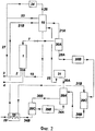
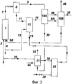
Сущность изобретения иллюстрируется прилагаемыми фиг.1-3. На фиг.1 изображена технологическая схема предложенной установки, на фиг.2 и 3 для сравнения приведены технологические схемы известных установок по US 3366682 и SU 839225, соответственно.The invention is illustrated by the attached figures 1-3. Figure 1 shows the technological scheme of the proposed installation, figure 2 and 3 for comparison shows the technological schemes of known installations according to US 3366682 and SU 839225, respectively.
В соответствии с фиг.1 установка включает колонну синтеза 1, трубопроводы для подачи жидкого аммиака 2 и 3, трубопроводы для подачи диоксида углерода 4 и 5, трубопровод 6 для подачи раствора УАС в колонну синтеза 1, трубопровод 7 для вывода раствора синтеза карбамида из колонны синтеза 1, сепаратор 8, трубопровод 9 для вывода газа из сепаратора 8, карбаматный конденсатор 10, трубопровод 11 для вывода раствора синтеза карбамида из сепаратора 8, стриппер 12, трубопровод 13 для подачи диоксида углерода в стриппер 12, трубопровод 14 для вывода газов из стриппера 12 в карбаматный конденсатор 10, трубопровод 15 для подачи раствора УАС в карбаматный конденсатор 10, промывную колонну 16, трубопровод 17 для вывода несконденсированных газов из карбаматного конденсатора 10, конденсатор среднего давления 18, трубопровод 19 для вывода раствора синтеза карбамида из стриппера 12, узел дистилляции среднего давления 20, трубопровод 21 для вывода газов дистилляции из узла 20 в конденсатор 18, трубопровод 22 для подачи газожидкостного потока из конденсатора 18 в промывную колонну 16, трубопровод 23 для подачи жидкого аммиака в промывную колонну 16, конденсатор аммиака 24, трубопровод 25 для подачи раствора УАС в промывную колонну 16, трубопровод 26 для вывода аммиака из промывной колонны 16 в конденсатор 24, трубопровод 27 для рециркуляции жидкого аммиака в колонну синтеза, трубопровод 28 для вывода раствора синтеза карбамида из узла дистилляции среднего давления 20, узел дистилляции низкого давления 29, трубопровод 30 для вывода газов дистилляции из узла 29, конденсатор низкого давления 31, трубопровод 32 для подачи раствора УАС из узла обработки сточных вод в конденсатор 31, трубопровод 33 для вывода несконденсированных газов из конденсатора 31, трубопровод 34 для вывода раствора карбамида из узла дистилляции низкого давления 29 на дальнейшую переработку.In accordance with figure 1, the installation includes a
Сущность способа и работа установки иллюстрируются также приведенными ниже примерами. Примеры 1-3 описывают осуществление предложенного способа на предложенной установке. Примеры 4 и 5 являются сравнительными и иллюстрируют осуществление известных способов на известных установках. Значения давлений во всех примерах, за исключением особо оговоренных случаев, являются значениями избыточного давления.The essence of the method and the operation of the installation are also illustrated by the following examples. Examples 1-3 describe the implementation of the proposed method on the proposed installation. Examples 4 and 5 are comparative and illustrate the implementation of known methods in known installations. The pressure values in all examples, except where otherwise indicated, are overpressure values.
Пример 1. В колонну синтеза 1, которая работает под давлением 20 МПа и при температуре 195°C, подают потоки аммиака 2 в количестве 51997 кг/ч (в том числе свежий аммиак 35438 кг/ч - поток 3), диоксида углерода 4 в количестве 22917 кг/ч (всего в агрегат подают 45833 кг/ч диоксида углерода - поток 5) и раствора УАС 6 (96926 кг/ч - 42,2% NH3, 44,7% CO2, 13,1% H2O). В колонне синтеза 1 происходит образование карбамида из поданных реагентов. Мольное соотношение NH3:CO2:H2O=3,63:1:0,47, степень конверсии С02 69,2%. Из колонны синтеза выходит раствор 7 (171840 кг/ч - 33,5% NH3, 11,9% CO2, 18,3% H2O, 36,4% карбамида), который после дросселирования до давления 9 МПа направляется в сепаратор 8. В сепараторе происходит разделение газовой и жидкой фаз. Газовая фаза 9 (22110 кг/ч - 81,8% NH3, 14,9% CO2, 3,3% H2O) направляется в карбаматный конденсатор 10 и зону конденсации среднего давления. Жидкая фаза 11 (149730 кг/ч - 26,3% NH3, 11,4% CO2, 20,5% H2O, 41,7% карбамида) направляется в стриппер 12. В стриппере под тем же давлением, что и в сепараторе - 9 МПа, происходит дистилляция раствора в токе подаваемого диоксида углерода (поток 13, 22917 кг/ч, 50% от общего количества, вводимого в процесс). Температура в нижней части стриппера поддерживается на уровне 170-180°C. Отогнанные в стриппере газы дистилляции 14 (65000 кг/ч - 42,4% NH3, 52,4% CO2, 5,2% H2O) направляются в карбаматный конденсатор 10. куда поступают также газы из сепаратора 8 и раствор УАС 15 (30415 кг/ч - 42,4% NH3, 30,1% CO2, 27,6% H2O) из промывной колонны 16. В карбаматном конденсаторе происходит конденсация газов дистилляции с образованием потока 6 раствора карбамата аммония, подаваемого в колонну синтеза 1. Не сконденсированная в конденсаторе 10 газовая фаза 17 (7769 кг/ч - 75,2% NH3, 22,5% CO2, 2,3% H2O), а также часть газовой фаз из сепаратора 9 дросселируется до давления 1,8 МПа и поступает в конденсатор среднего давления 18, входящий в состав устройства для конденсации-абсорбции газов дистилляции первой ступени, куда входят также промывная колонна 16, конденсатор аммиака 24 и трубопроводы 22, 23 и 26. Раствор 19 (107646 кг/ч - 11,0% NH3, 5,6% CO2, 25,4% H2O, 58,1% карбамида) из стриппера 12 дросселируется до давления 1,8 МПа и поступает в узел дистилляции среднего давления 20, где производится отгонка из раствора аммиака, диоксида углерода и воды. Газы дистилляции 21 (20608 кг/ч - 45,2% NH3, 25,5% CO2, 29,3% H2O) из узла 20 направляются в конденсатор 18, где происходит их конденсация при давлении 1,8 МПа совместно с газовой фазой из карбаматного конденсатора 10. Полученный газожидкостный поток 22 (44518 кг/ч - 63,7% NH3, 21,5% CO2, 15,2% H2O) подается в промывную колонну 16 для разделения фаз и отмывки газовой фазы от диоксида углерода. В промывную колонну также подают жидкий аммиак 23 из конденсатора 24 и раствор УАС 25 (5767 кг/ч - 43,2% NH3, 12,7% CO2, 44,2% H2O) из узла конденсации под давлением 0,3 МПа. Газовая фаза 26 из промывной колонны (25654 кг/ч - 100% NH3) направляется в конденсатор 24. Сконденсированный аммиак частично возвращается в виде флегмы в промывную колонну 16 (поток 23), а остальная его часть (поток 27 - 16559 кг/ч) поступает на рециркуляцию в узел синтеза. Полученный в промывной колонне раствор УАС 15 подают в карбаматный конденсатор 10. Раствор 28 (87038 кг/ч - 2,9% NH3, 0,8% CO2, 24,5% H2O, 71,8% карбамида) из узла дистилляции под давлением 1,8 МПа дросселируется и поступает в узел дистилляции 29, где при давлении 0,3 МПа производится отгонка из раствора аммиака, диоксида углерода и воды. Газы дистилляции 30 (5048 кг/ч - 45,2% NH3, 11,9% CO2, 42,9% H2O) направляются в конденсатор 31. Сюда же из узла обработки сточных вод (на фиг.1 не показан) подают раствор УАС 32 (1360 кг/ч - 35,8% NH3, 15,4% - CO2, 48,9% H2O) для улучшения условий конденсации. Полученный в конденсаторе 31 раствор УАС (поток 25) подают в промывную колонну 16, а несконденсированную газовую фазу 33 (641 кг/ч - 43,2% NH3, 12,7% CO2, 44,2% H2O) направляют на дальнейшую переработку. Раствор 34 (81990 кг/ч - 0,3% NH3, 0,2% CO2, 23,3% H2O, 76,2% карбамида) после узла дистилляции под давлением 0,3 МПа дросселируется и направляется на переработку известными методами в готовый продукт - карбамид. Составы и количества потоков по этому и двум последующим примерам приведены в прилагаемой таблице.Example 1. In the
Пример 2. Процесс проводят аналогично примеру 1 с тем отличием, что в сепараторе 8, карбаматном конденсаторе 10 и стриппере 12 поддерживают давление 8 МПа.Example 2. The process is carried out analogously to example 1 with the difference that in the
Пример 3. Процесс проводят аналогично примеру 1 с тем отличием, что в сепараторе 8, карбаматном конденсаторе 10 и стриппере 12 поддерживают давление 12 МПа.Example 3. The process is carried out analogously to example 1 with the difference that in the
Пример 4 (сравнительный, по прототипу). В колонну синтеза 1, работающую при давлении 20 МПа и температуре 190°C, подают аммиак (поток 2) в количестве 80896 кг/ч (в том числе свежий аммиак - поток 3 - 35417 кг/ч), диоксид углерода (поток 4) в количестве 46774 кг/ч, а также раствор УАС 15 (59043 кг/ч - 36,9% NH3, 33,3% CO2, 29,9% H2O). В колонне 1 мольное соотношение NH3:CO2:H2O=4,0:1: 0,65, степень конверсии CO2 69,0%. Полученный раствор карбамида 7 (186713 кг/ч - 36,0% NH3, 11,0% CO2, 19,5% H2O, 33,5% карбамида) выводят из колонны 1, дросселируют до давления 1,7 МПа и при температуре 125°C подают в сепаратор 20A узла дистилляции среднего давления. В сепараторе происходит разделение потока на выделившиеся газы 21A (35166 кг/ч - 86,0% NH3, 8,8% CO2, 5,2% H2O), которые направляются в промывную колонну 16, и раствор карбамида 28A (151547 кг/ч - 24,4% NH3, 11,6% CO2, 22,8% H2O, 41,2% карбамид), который направляется в подогреватель 20B. Здесь он подогревается до температуры 160°C и поступает в сепаратор 20С, где отделяются газы дистилляции 21B (45331 кг/ч - 55,5% NH3, 30,0% CO2, 14,6% H 2 O ), которые через рекуператор 35 направляются в промывную колонну 16. Раствор карбамида 28B (106215 кг/ч - 11,1% NH3, 3,7% CO2, 26,3% H2O, 58,8% карбамид) из сепаратора 20C дросселируется до давления 0,4 МПа и поступает в колонну дистилляции 29A для дальнейшего выделения непрореагировавших компонентов и воды. Из колонны дистилляции газы 30A (22045 кг/ч - 47,0% NH3, 13,5% CO2, 39,5% H 2 O ) поступают на конденсацию в узел конденсации 31, а раствор карбамида 34А (97332 кг/ч - 6,1% NH3, 2,4% CO2, 27,3% H2O, 64,2% карбамид) - в подогреватель 29В, где он подогревается и поступает в сепаратор 29С. Газы дистилляции 30B (11162 кг/ч - 39,8% NH3, 12,7% CO2, 47,6% H2O) из сепаратора 29C передаются в колонну дистилляции 29А для улучшения условий массообмена. Раствор карбамида 34B (86170 кг/ч - 1,7% NH3, 1,1% CO2, 24,7% H2O, 72,5% карбамид) дросселируется до давления 0,04 МПа (абс.) и при температуре 105°C подается в рекуператор 35, где за счет тепла газов дистилляции 20 происходит нагрев его до 125°C. Полученный раствор 34B передается на стадию концентрирования и переработки в готовый продукт - карбамид. Газы дистилляции 21 В после рекуператора 35 подают в промывную колонну 16. Сюда же подают раствор УАС 25 (22045 кг/ч - 47,0% NH3, 13,5% CO2, 39,5% H2O) из узла конденсации 31, а также часть жидкого аммиака (поток 23; 40000 кг/ч - 100% NH3) из конденсатора 24. В промывной колонне происходит отмывка газов дистилляции от диоксида углерода с помощью подаваемого жидкого аммиака и раствора УАС. Раствор УАС 15 из промывной колонны направляют в реактор синтеза 1, газообразный аммиак 26 (84000 кг/ч - 100% NH3) из промывной колонны - на конденсацию в конденсатор 24. Часть сконденсированного аммиака подают на орошение промывной колонны, а остальное (поток 27) - в колонну синтеза.Example 4 (comparative, prototype). Ammonia (stream 2) in an amount of 80896 kg / h (including fresh ammonia - stream 3 - 35417 kg / h), carbon dioxide (stream 4) is fed to
Пример 5 (сравнительный, по SU 839225). В колонну синтеза 1, в которой поддерживают температуру 200°C и давление 25 МПа, подают аммиак (поток 2) в количестве 30599 кг/ч, диоксид углерода (поток 4) в количестве 32199 кг/ч и раствор УАС 6B (130116 кг/ч - 52% NH3 32% CO2, 16% H2O) из конденсатора 10B. Мольное соотношение в колонне NH3:CO2:H2O=3,46:1:0,69, степень конверсии CO2 62,0%. Раствор карбамида 7 (193827 кг/ч - 32,7% NH3, 14,5% CO2, 20,5% H2O, 32,3% карбамида), выходящий из колонны синтеза 1, дросселируют до 9 МПа и подают в сепаратор 8, где отделяется часть избыточного аммиака (поток 9). Раствор 11 (157285 кг/ч, 22,5% NH3, 12,4% CO2, 25,2% Н2О, 39,9% карбамида) из сепаратора 8 поступает в стриппер 12, где при том же давлении и при 165-175°C его подвергают дистилляции в токе CO2 (поток 13, 13800 кг/ч). Раствор 19 (114514 кг/ч - 7% NH3, 9% CO2, 29% H2O, 55% карбамид) из стриппера 12 дросселируют до 0,25 МПа и подают в колонну дистилляции низкого давления 29. Из колонны дистилляции 29 раствор мочевины 34 (93162 кг/ч - 0,75% NH3, 0,95% CO2, 31% H2O, 67,3% карбамида) дросселируют и направляют на переработку известными методами в готовый карбамид. Газовую фазу 9 (36542 кг/ч - 76,5% NH3, 23,5% CO2) из сепаратора 8 и газовую фазу 14 из стриппера 12 направляют на стадию конденсации при давлении 9 МПа в конденсатор 10А, куда подают раствор УАС 25 (34821 кг/ч - 33% NH3, 30% CO2, 37% H2O) из конденсатора 31 стадии дистилляции при давлении 0,25 МПа. Из конденсатора 10А раствор УАС 6А (96218 кг/ч - 36,3% NH3, 43,6% CO2, 20,1% H2O) и газовую фазу 36 (33397 кг/ч - 100% NH3) направляют во второй конденсатор 10 В при том же давлении. В конденсатор 10B подают воду 37 (500 кг/ч). Инертные газы 38 передают на дальнейшую переработку. Газовую фазу 30 из колонны дистилляции 29 направляют в конденсатор 31. Для полноты конденсации газов в конденсатор 31 подают также жидкий аммиак 39 (5000 кг/ч) и воду 40 (7500 кг/ч). Газовую фазу 33 из конденсатора 31 передают на дальнейшую переработку.Example 5 (comparative, according to SU 839225). Ammonia (stream 2) in an amount of 30599 kg / h, carbon dioxide (stream 4) in an amount of 32199 kg / h and a solution of
Claims (3)
Priority Applications (6)
| Application Number | Priority Date | Filing Date | Title |
|---|---|---|---|
| RU2012134931/04A RU2499791C1 (en) | 2012-08-15 | 2012-08-15 | Method and apparatus for producing carbamide and method of upgrading apparatus for producing carbamide |
| UAA201500964A UA112806C2 (en) | 2012-08-15 | 2013-05-08 | METHOD AND INSTALLATION FOR CARBAMIDE PRODUCTION AND METHOD OF MODERNIZATION OF CARBAMIDE PRODUCTION |
| PCT/RU2013/000671 WO2014027929A1 (en) | 2012-08-15 | 2013-08-05 | Urea production process and plant and method for modernizing a urea production plant |
| IN1008DEN2015 IN2015DN01008A (en) | 2012-08-15 | 2013-08-05 | |
| TR2015/01111T TR201501111T1 (en) | 2012-08-15 | 2013-08-05 | Process and facility for urea production and method for modernization of urea plants. |
| GEAP201313734A GEP201706706B (en) | 2012-08-15 | 2013-08-05 | Urea production process and plant and method for modernization urea roduction plant |
Applications Claiming Priority (1)
| Application Number | Priority Date | Filing Date | Title |
|---|---|---|---|
| RU2012134931/04A RU2499791C1 (en) | 2012-08-15 | 2012-08-15 | Method and apparatus for producing carbamide and method of upgrading apparatus for producing carbamide |
Publications (1)
| Publication Number | Publication Date |
|---|---|
| RU2499791C1 true RU2499791C1 (en) | 2013-11-27 |
Family
ID=49710505
Family Applications (1)
| Application Number | Title | Priority Date | Filing Date |
|---|---|---|---|
| RU2012134931/04A RU2499791C1 (en) | 2012-08-15 | 2012-08-15 | Method and apparatus for producing carbamide and method of upgrading apparatus for producing carbamide |
Country Status (6)
| Country | Link |
|---|---|
| GE (1) | GEP201706706B (en) |
| IN (1) | IN2015DN01008A (en) |
| RU (1) | RU2499791C1 (en) |
| TR (1) | TR201501111T1 (en) |
| UA (1) | UA112806C2 (en) |
| WO (1) | WO2014027929A1 (en) |
Cited By (2)
| Publication number | Priority date | Publication date | Assignee | Title |
|---|---|---|---|---|
| RU201591U1 (en) * | 2020-07-09 | 2020-12-22 | Акционерное общество "Аммоний" | UNIT OF CONCENTRATION OF CARBAMIDE SOLUTION |
| RU2811862C1 (en) * | 2023-02-16 | 2024-01-18 | Акционерное общество "Научно-исследовательский и проектный институт карбамида и продуктов органического синтеза" (АО "НИИК") | Method and installation for producing urea |
Families Citing this family (1)
| Publication number | Priority date | Publication date | Assignee | Title |
|---|---|---|---|---|
| US10857480B2 (en) | 2017-10-27 | 2020-12-08 | Stamicarbon B.V. | High pressure carbamate condenser |
Citations (2)
| Publication number | Priority date | Publication date | Assignee | Title |
|---|---|---|---|---|
| US3366682A (en) * | 1964-05-29 | 1968-01-30 | Stamicarbon | Process for the preparation of urea |
| SU839225A1 (en) * | 1979-07-12 | 1984-05-15 | Предприятие П/Я Г-4302 | Process for producing urea |
-
2012
- 2012-08-15 RU RU2012134931/04A patent/RU2499791C1/en active IP Right Revival
-
2013
- 2013-05-08 UA UAA201500964A patent/UA112806C2/en unknown
- 2013-08-05 IN IN1008DEN2015 patent/IN2015DN01008A/en unknown
- 2013-08-05 GE GEAP201313734A patent/GEP201706706B/en unknown
- 2013-08-05 WO PCT/RU2013/000671 patent/WO2014027929A1/en active Application Filing
- 2013-08-05 TR TR2015/01111T patent/TR201501111T1/en unknown
Patent Citations (2)
| Publication number | Priority date | Publication date | Assignee | Title |
|---|---|---|---|---|
| US3366682A (en) * | 1964-05-29 | 1968-01-30 | Stamicarbon | Process for the preparation of urea |
| SU839225A1 (en) * | 1979-07-12 | 1984-05-15 | Предприятие П/Я Г-4302 | Process for producing urea |
Non-Patent Citations (1)
| Title |
|---|
| Кучерявый В.И. и др. Синтез и применение карбамида. - Л.: Химия, 1970, с.187-208. * |
Cited By (2)
| Publication number | Priority date | Publication date | Assignee | Title |
|---|---|---|---|---|
| RU201591U1 (en) * | 2020-07-09 | 2020-12-22 | Акционерное общество "Аммоний" | UNIT OF CONCENTRATION OF CARBAMIDE SOLUTION |
| RU2811862C1 (en) * | 2023-02-16 | 2024-01-18 | Акционерное общество "Научно-исследовательский и проектный институт карбамида и продуктов органического синтеза" (АО "НИИК") | Method and installation for producing urea |
Also Published As
| Publication number | Publication date |
|---|---|
| WO2014027929A1 (en) | 2014-02-20 |
| GEP201706706B (en) | 2017-07-25 |
| UA112806C2 (en) | 2016-10-25 |
| IN2015DN01008A (en) | 2015-06-12 |
| TR201501111T1 (en) | 2018-11-21 |
Similar Documents
| Publication | Publication Date | Title |
|---|---|---|
| KR100622880B1 (en) | Integrated deethanizer/ethylene fractionnation column | |
| RU2446152C2 (en) | Method of producing urea and apparatus for realising said method | |
| EP1203765A2 (en) | Process for the synthesis of urea | |
| CN108026034B (en) | Process for producing urea and apparatus for producing urea | |
| CN109890788B (en) | Integrated process of urea and urea-ammonium nitrate | |
| EA034482B1 (en) | Integrated production of urea and melamine | |
| RU2412163C2 (en) | Method and apparatus for producing urea | |
| EA028930B1 (en) | Urea synthesis process and plant | |
| EP2521710B1 (en) | A urea stripping process for the production of urea | |
| CN108689798B (en) | Method for improving quality of methyl chloride recovered by synthesizing organic silicon monomer | |
| RU2131868C1 (en) | Urea production process (versions) and installation | |
| RU2499791C1 (en) | Method and apparatus for producing carbamide and method of upgrading apparatus for producing carbamide | |
| KR102466816B1 (en) | Evaporation system comprising a series of evaporators for treating an ammoxidation process stream | |
| KR101320276B1 (en) | Method for concentrating an aqueous ammonium carbamate stream | |
| US5597454A (en) | Process for producing urea | |
| US5380943A (en) | Process and plant for the production of urea with differentiated yield reaction spaces | |
| RU2454403C1 (en) | Method of producing carbamide | |
| US4311856A (en) | Process for synthesizing urea | |
| SU1153825A3 (en) | Method of obtaining urea | |
| CN1219755C (en) | Process for decomposing a carbamate, aqueous solution coming from the urea recovery section of a urea production plant | |
| RU2426715C2 (en) | Method and apparatus for homogeneous oxidation of methane-containing gas | |
| RU2050351C1 (en) | Method of carbamide synthesis | |
| EA029247B1 (en) | Urea plant revamping method | |
| GB2089786A (en) | Process for synthesizing urea | |
| AU702000B2 (en) | Method and apparatus for recovering condensables in vapor from a urea vacuum evaporator |
Legal Events
| Date | Code | Title | Description |
|---|---|---|---|
| MM4A | The patent is invalid due to non-payment of fees |
Effective date: 20160816 |
|
| NF4A | Reinstatement of patent |
Effective date: 20170418 |
|
| QB4A | Licence on use of patent |
Free format text: LICENCE FORMERLY AGREED ON 20200723 Effective date: 20200723 |