RU2494792C2 - Disperser of sprayer-drier absorber - Google Patents
Disperser of sprayer-drier absorber Download PDFInfo
- Publication number
- RU2494792C2 RU2494792C2 RU2010138605/02A RU2010138605A RU2494792C2 RU 2494792 C2 RU2494792 C2 RU 2494792C2 RU 2010138605/02 A RU2010138605/02 A RU 2010138605/02A RU 2010138605 A RU2010138605 A RU 2010138605A RU 2494792 C2 RU2494792 C2 RU 2494792C2
- Authority
- RU
- Russia
- Prior art keywords
- spray drying
- dispersants
- dispersant
- drying chamber
- process gas
- Prior art date
Links
- 239000006096 absorbing agent Substances 0.000 title claims abstract description 91
- 238000000034 method Methods 0.000 claims abstract description 50
- 230000008569 process Effects 0.000 claims abstract description 40
- 239000000126 substance Substances 0.000 claims abstract description 14
- 239000000356 contaminant Substances 0.000 claims abstract description 4
- 239000002270 dispersing agent Substances 0.000 claims description 180
- 238000001694 spray drying Methods 0.000 claims description 144
- 239000007921 spray Substances 0.000 claims description 40
- 239000007788 liquid Substances 0.000 claims description 37
- 230000009931 harmful effect Effects 0.000 claims description 14
- 230000000694 effects Effects 0.000 abstract description 4
- 238000010327 methods by industry Methods 0.000 abstract 1
- UGFAIRIUMAVXCW-UHFFFAOYSA-N Carbon monoxide Chemical compound [O+]#[C-] UGFAIRIUMAVXCW-UHFFFAOYSA-N 0.000 description 57
- 239000003546 flue gas Substances 0.000 description 57
- 239000007789 gas Substances 0.000 description 45
- XLYOFNOQVPJJNP-UHFFFAOYSA-N water Substances O XLYOFNOQVPJJNP-UHFFFAOYSA-N 0.000 description 11
- RAHZWNYVWXNFOC-UHFFFAOYSA-N Sulphur dioxide Chemical compound O=S=O RAHZWNYVWXNFOC-UHFFFAOYSA-N 0.000 description 8
- 230000015572 biosynthetic process Effects 0.000 description 8
- 238000001035 drying Methods 0.000 description 8
- 230000008901 benefit Effects 0.000 description 4
- 238000009434 installation Methods 0.000 description 4
- 238000010521 absorption reaction Methods 0.000 description 3
- 239000003245 coal Substances 0.000 description 3
- 239000000428 dust Substances 0.000 description 3
- 239000012717 electrostatic precipitator Substances 0.000 description 3
- 239000000446 fuel Substances 0.000 description 3
- 238000002156 mixing Methods 0.000 description 3
- 239000003921 oil Substances 0.000 description 3
- 239000002245 particle Substances 0.000 description 3
- 235000019738 Limestone Nutrition 0.000 description 2
- 239000002253 acid Substances 0.000 description 2
- 230000002378 acidificating effect Effects 0.000 description 2
- 239000007900 aqueous suspension Substances 0.000 description 2
- 238000002485 combustion reaction Methods 0.000 description 2
- 230000003116 impacting effect Effects 0.000 description 2
- 239000006028 limestone Substances 0.000 description 2
- 238000012986 modification Methods 0.000 description 2
- 230000004048 modification Effects 0.000 description 2
- 239000007787 solid Substances 0.000 description 2
- 239000000725 suspension Substances 0.000 description 2
- 241001640558 Cotoneaster horizontalis Species 0.000 description 1
- 241000196324 Embryophyta Species 0.000 description 1
- 230000002745 absorbent Effects 0.000 description 1
- 239000002250 absorbent Substances 0.000 description 1
- 230000009471 action Effects 0.000 description 1
- 230000002411 adverse Effects 0.000 description 1
- 230000002776 aggregation Effects 0.000 description 1
- 238000004220 aggregation Methods 0.000 description 1
- 238000010586 diagram Methods 0.000 description 1
- 238000001914 filtration Methods 0.000 description 1
- 239000002737 fuel gas Substances 0.000 description 1
- 239000000463 material Substances 0.000 description 1
- 239000003415 peat Substances 0.000 description 1
- 230000009467 reduction Effects 0.000 description 1
- 239000002002 slurry Substances 0.000 description 1
- 239000002699 waste material Substances 0.000 description 1
- 230000003313 weakening effect Effects 0.000 description 1
Images
Classifications
-
- B—PERFORMING OPERATIONS; TRANSPORTING
- B01—PHYSICAL OR CHEMICAL PROCESSES OR APPARATUS IN GENERAL
- B01D—SEPARATION
- B01D53/00—Separation of gases or vapours; Recovering vapours of volatile solvents from gases; Chemical or biological purification of waste gases, e.g. engine exhaust gases, smoke, fumes, flue gases, aerosols
- B01D53/34—Chemical or biological purification of waste gases
- B01D53/46—Removing components of defined structure
- B01D53/48—Sulfur compounds
- B01D53/50—Sulfur oxides
- B01D53/501—Sulfur oxides by treating the gases with a solution or a suspension of an alkali or earth-alkali or ammonium compound
- B01D53/505—Sulfur oxides by treating the gases with a solution or a suspension of an alkali or earth-alkali or ammonium compound in a spray drying process
-
- B—PERFORMING OPERATIONS; TRANSPORTING
- B01—PHYSICAL OR CHEMICAL PROCESSES OR APPARATUS IN GENERAL
- B01D—SEPARATION
- B01D2251/00—Reactants
- B01D2251/40—Alkaline earth metal or magnesium compounds
- B01D2251/404—Alkaline earth metal or magnesium compounds of calcium
Landscapes
- Chemical & Material Sciences (AREA)
- Engineering & Computer Science (AREA)
- General Chemical & Material Sciences (AREA)
- Environmental & Geological Engineering (AREA)
- Biomedical Technology (AREA)
- Analytical Chemistry (AREA)
- Health & Medical Sciences (AREA)
- Oil, Petroleum & Natural Gas (AREA)
- Chemical Kinetics & Catalysis (AREA)
- Gas Separation By Absorption (AREA)
- Treating Waste Gases (AREA)
- Drying Of Solid Materials (AREA)
- Vaporization, Distillation, Condensation, Sublimation, And Cold Traps (AREA)
Abstract
Description
ОБЛАСТЬ ИЗОБРЕТЕНИЯFIELD OF THE INVENTION
Настоящее изобретение относится к распылительному сушильному абсорберу, который служит для удаления газообразных загрязняющих веществ из горячего технологического газа и включает распылительную сушильную камеру и по меньшей мере два диспергатора, смонтированных на крыше распылительной сушильной камеры, где каждый такой диспергатор служит для диспергирования части горячего технологического газа вокруг соответствующего распылителя, который распыляет поглощающую жидкость, причем каждый диспергатор снабжен устройством направления потока, которое придает части горячего технологического газа вращательное движение вокруг распылителя, если смотреть с верха распылительной сушильной камеры.The present invention relates to a spray drying absorber, which serves to remove gaseous contaminants from a hot process gas and includes a spray drying chamber and at least two dispersants mounted on the roof of the spray drying chamber, where each such dispersant serves to disperse a portion of the hot process gas around a respective atomizer that atomizes the absorbing liquid, each dispersant provided with a directional device the flow that imparts a portion of the hot process gas to a rotational movement around the atomizer when viewed from the top of the spray drying chamber.
Настоящее изобретение относится далее к способу удаления газообразных вредных веществ из горячего технологического газа посредством распылительного сушильного абсорбера.The present invention further relates to a method for removing gaseous harmful substances from a hot process gas by means of a spray drying absorber.
ПРЕДПОСЫЛКИ СОЗДАНИЯ ИЗОБРЕТЕНИЯBACKGROUND OF THE INVENTION
При сжигании топлива, такого как уголь, нефть, торф, отходы и т.д. на установках сжигания, таких как силовые установки, образуется горячий технологический газ, такой горячий технологический газ, часто называемый дымовым газом, содержит вредные вещества, включая кислые газы, такие как двуокись серы, SO2. Необходимо удалить насколько возможно больше кислых газов из дымового газа, прежде чем дымовой газ сможет быть выпущен в окружающую атмосферу. Для удаления кислых газов, включая двуокись серы, из дымового газа может быть использован распылительный сушильный абсорбер.When burning fuels such as coal, oil, peat, waste, etc. In combustion plants such as power plants, hot process gas is generated, such a hot process gas, often called flue gas, contains harmful substances, including acidic gases such as sulfur dioxide, SO 2 . It is necessary to remove as much acid gas from the flue gas as possible before the flue gas can be released into the surrounding atmosphere. A spray drying absorber may be used to remove acidic gases, including sulfur dioxide, from flue gas.
Пример распылительного сушильного абсорбера можно найти в US 4755366. Распылительный сушильный абсорбер включает камеру, которая снабжена вращающимся распылителем, имеющим распыляющее колесо. Во вращающийся распылитель подают водную суспензию, иногда называемую взвесью, которая включает абсорбент, такой как известняк. Колесо распылителя вращается с большим числом оборотов в минуту и распыляет водную суспензию так, что образуются очень мелкие капли. Мелкие капли поглощают кислые газовые компоненты из дымового газа и затем образуют твердый остаток благодаря эффекту сушки в распылительном сушильном абсорбере.An example of a spray drying absorber can be found in US 4,755,366. A spray drying absorber includes a chamber that is provided with a rotary spray having a spray wheel. An aqueous suspension, sometimes called a suspension, which includes an absorbent such as limestone, is fed into the rotary atomizer. The sprayer wheel rotates at a high speed per minute and sprays the aqueous suspension so that very small droplets form. Small droplets absorb acid gas components from the flue gas and then form a solid residue due to the drying effect in the spray drying absorber.
Проблемой распылительного сушильного абсорбера по US 4755366 является то, что трудно увеличить пропускную способность единичного распылительного сушильного абсорбера по отношению к расходу дымового газа. Одной из причин этого затруднения является то, что очень высокое число оборотов распыляющего колеса создает механические препятствия увеличению его размера. Таким образом, часто становится необходимо соорудить два, три или более параллельных абсорбционных камер распылительной сушки для того, чтобы приспособиться к более высоким расходам дымового газа.A problem with the spray drying absorber according to US 4,755,366 is that it is difficult to increase the throughput of a single spray drying absorber with respect to the flue gas flow rate. One of the reasons for this difficulty is that the very high number of revolutions of the spray wheel creates mechanical obstacles to increasing its size. Thus, it often becomes necessary to construct two, three or more parallel absorption drying chambers in order to adapt to higher flue gas flow rates.
СУЩНОСТЬ ИЗОБРЕТЕНИЯSUMMARY OF THE INVENTION
Задачей настоящего изобретения является предложить распылительный сушильный абсорбер, который может быть рассчитан на более высокие расходы дымового газа, чем распылительный сушильный абсорбер и по прототипу.The present invention is to provide a spray drying absorber, which can be designed for higher flue gas consumption than a spray drying absorber and the prototype.
Эта задача достигается посредством распылительного сушильного абсорбера, который служит для удаления газообразных загрязняющих веществ из горячего технологического газа и включает распылительную сушильную камеру и по меньшей мере два диспергатора, смонтированных на крыше распылительной сушильной камеры, где каждый такой диспергатор служит для диспергирования части горячего технологического газа вокруг соответствующего распылителя, который распыляет поглощающую жидкость, причем каждый диспергатор снабжен устройством направления потока, которое придает соответствующей части горячего технологического газа вращательное движение вокруг распылителя, если смотреть сверху распылительной сушильной камеры, где распылительный сушильный абсорбер отличается тем, что указанные по меньшей мере два диспергатора расположены на практически одинаковом расстоянии от периферии распылительной сушильной камеры, устройство направления потока по меньшей мере одного определенного диспергатора из указанных по меньшей мере двух диспергаторов служит для придания указанной части горячего технологического газа, проходящей через этот определенный диспергатор, вращательного движения в направлении, которое противоположно направлению вращательного движения соответствующей части горячего технологического газа, диспергируемой по меньшей мере одним другим диспергатором, расположенным наиболее близко к указанному по меньшей мере одному определенному диспергатору, если смотреть по периферии распылительной сушильной камеры.This objective is achieved by spray drying the absorber, which serves to remove gaseous contaminants from the hot process gas and includes a spray drying chamber and at least two dispersants mounted on the roof of the spray drying chamber, where each such dispersant serves to disperse a portion of the hot process gas around a respective atomizer that atomizes the absorbing liquid, each dispersant provided with a guiding device the flow, which gives the corresponding part of the hot process gas a rotational movement around the spray gun when viewed from above the spray drying chamber, where the spray drying absorber is characterized in that said at least two dispersing agents are located at almost the same distance from the periphery of the spray drying chamber, at least one particular dispersant of said at least two dispersants serves to impart said portion hot process gas passing through this particular dispersant, rotational motion in a direction that is opposite to the direction of rotational motion of the corresponding part of the hot process gas dispersed by at least one other dispersant located closest to the specified at least one particular dispersant, as viewed from the periphery spray drying chamber.
Преимуществом этого распылительного сушильного абсорбера является то, что два или более диспергатора могут быть установлены в одной и той же распылительной сушильной камере без того, чтобы эти диспергаторы влияли друг на друга отрицательным образом. Следовательно, пропускная способность по отношению к потоку дымового газа и по отношению к потоку поглощающей жидкости одного распылительного сушильного абсорбера может быть повышена, еще сохраняя эффективную сушку капель жидкости и эффективное удаление газообразных вредных веществ.An advantage of this spray drying absorber is that two or more dispersants can be installed in the same spray drying chamber without these dispersants adversely affecting each other. Therefore, the throughput with respect to the flue gas stream and with respect to the flow of the absorbing liquid of one spray drying absorber can be increased, while still maintaining the effective drying of the liquid droplets and the effective removal of gaseous harmful substances.
Согласно одному осуществлению распылительного сушильного абсорбера включает по меньшей мере три диспергатора, где максимум два следующих друг за другом диспергатора из указанных по меньшей мере трех диспергаторов, если смотреть по периферии распылительной сушильной камеры, работают для придания подаваемого туда горячего технологического газа вращательного движения в одном и том же направлении. Преимуществом этого осуществления является то, что минимизируется вредное влияние на смешение между процессным газом и каплями жидкости, которое может быть вызвано соседними диспергаторами, придающими поступающему к ним газу одинаковое направление вращательного движения. Предпочтительно, когда общее число диспергаторов является четным, таким как в распылительном сушильном абсорбере с суммарно 4, 6 или 8 диспергаторами, каждый определенный диспергатор придает поступающему туда газу направление вращательного движения, которое противоположно направлению вращательного движения, придаваемому соответствующим частям процессного газа, поступающим к ближайшим соседним к этому определенному диспергатору диспергаторам. Если общее число диспергаторов нечетно, как в распылительных сушильных абсорберах с суммарно 3, 5, 7 или 9 диспергаторами, случаи наличия двух следующих друг за другом диспергаторов, придающих поступающему в них процессному газу одинаковое направление вращательного движения, минимизируют, чтобы иметь в этом распылительном сушильном абсорбере только один случай двух следующих друг за другом диспергаторов, придающих процессному газу одинаковое направление вращательного движения.According to one embodiment of the spray drying absorber, it comprises at least three dispersants, where a maximum of two successive dispersants from the at least three dispersants, when viewed around the periphery of the spray drying chamber, operate to give the hot process gas supplied therein a rotational movement in one and in the same direction. The advantage of this embodiment is that the harmful effect on mixing between the process gas and liquid droplets, which can be caused by adjacent dispersants, giving the incoming gas the same direction of rotational motion, is minimized. Preferably, when the total number of dispersants is even, such as in a spray drying absorber with a total of 4, 6, or 8 dispersants, each particular dispersant gives the incoming gas a direction of rotational motion that is opposite to the direction of rotational motion given to the corresponding parts of the process gas to the nearest adjacent to this particular dispersant are dispersants. If the total number of dispersants is odd, as in spray drying absorbers with a total of 3, 5, 7, or 9 dispersants, the occurrence of two successive dispersants giving the process gas flowing into them the same direction of rotational motion is minimized to have in this spray drying the absorber is only one case of two successive dispersants giving the process gas the same direction of rotational motion.
Согласно одному осуществлению распылительная сушильная камера является круговой, если смотреть сверху. Преимуществом этого осуществления является то, что можно избежать вредных эффектов, связанных с потоком газа в углах абсорбера. Кроме того, круговая распылительная сушильная камера позволяет легче расположить диспергаторы в подходящих положениях относительно друг друга в отношении свойств газового потока.According to one embodiment, the spray drying chamber is circular as viewed from above. An advantage of this embodiment is that harmful effects associated with the gas flow in the corners of the absorber can be avoided. In addition, the circular spray drying chamber makes it easier to arrange the dispersants in suitable positions relative to each other with respect to the properties of the gas stream.
Согласно одному осуществлению общее число диспергаторов составляет от 2 до 9. Было найдено, что такое число дает распылительный сушильный абсорбер, который эффективен и в отношении капиталовложений, и в отношении удаления газообразных вредных веществ.According to one embodiment, the total number of dispersants is from 2 to 9. It has been found that such a number gives a spray drying absorber that is effective both in terms of investment and in the removal of gaseous harmful substances.
Следующей задачей настоящего изобретения является предложить способ удаления газообразных вредных веществ из больших объемов горячего технологического газа посредством распылительного сушильного абсорбера, более эффективный в отношении капиталовложений и эффективности удаления загрязнений, чем способы прототипа.The next objective of the present invention is to provide a method of removing gaseous harmful substances from large volumes of hot process gas by means of a spray drying absorber, more effective in terms of investment and removal efficiency than prototype methods.
Эта задача достигается посредством способа удаления газообразных вредных веществ из горячего технологического газа посредством распылительного сушильного абсорбера, включающего распылительную сушильную камеру и по меньшей мере два диспергатора, смонтированных на крыше распылительной сушильной камеры, где каждый такой диспергатор служит для диспергирования части горячего технологического газа вокруг соответствующего распылителя, который распыляет поглощающую жидкость, причем каждый диспергатор снабжен устройством направления потока, которое придает соответствующей части горячего технологического газа вращательное движение вокруг распылителя, если смотреть с верху распылительной сушильной камеры, где способ отличается тем, что заставляет соответствующую часть горячего технологического газа, проходящую через по меньшей мере один определенный диспергатор из указанных по меньшей мере двух диспергаторов приобрести вращательное движение в направлении, которое противоположно направлению вращательного движения соответствующей части горячего технологического газа, диспергируемой по меньшей мере одним другим диспергатором, расположенным наиболее близко к указанному по меньшей мере одному определенному диспергатору, если смотреть по периферии распылительной сушильной камеры.This objective is achieved by a method of removing gaseous harmful substances from a hot process gas by means of a spray drying absorber comprising a spray drying chamber and at least two dispersants mounted on the roof of the spray drying chamber, where each such dispersant serves to disperse a portion of the hot process gas around a respective spray gun which atomizes the absorbing liquid, with each dispersant provided with a directional device n outflow, which gives the corresponding part of the hot process gas a rotational movement around the atomizer when viewed from the top of the spray drying chamber, where the method is characterized in that it forces the corresponding part of the hot process gas passing through at least one specific dispersant of the at least two dispersants acquire rotational motion in a direction that is opposite to the direction of rotational motion of the corresponding part of the hot technological about gas dispersible by at least one other dispersant located closest to the specified at least one particular dispersant, as seen from the periphery of the spray drying chamber.
Преимуществом этого способа является то, что риск получения нежелательных эффектов, таких как образование крупных капель, ослабление вращательного движения и т.д., уменьшен в тех областях, где взаимодействуют поля течения диспергаторов, расположенных смежно друг к другу. Это повышает эффективность удаления газообразных вредных веществ из горячего технологического газа и сушки капель поглощающей жидкости.The advantage of this method is that the risk of undesirable effects, such as the formation of large droplets, the weakening of rotational motion, etc., is reduced in those areas where the flow fields of dispersants adjacent to each other interact. This increases the efficiency of removing gaseous harmful substances from the hot process gas and drying the drops of the absorbing liquid.
Согласно одному осуществлению способа указанный распылительный сушильный абсорбер включает по меньшей мере три диспергатора, где максимум два следующих друг за другом диспергатора из указанных по меньшей мере трех диспергаторов, если смотреть по периферии распылительной сушильной камеры, работают для придания подаваемому туда дымовому газу вращательного движения в том же направлении.According to one embodiment of the method, said spray drying absorber comprises at least three dispersants, wherein a maximum of two consecutive dispersants of the at least three dispersants, when viewed from the periphery of the spray drying chamber, operate to rotate the flue gas supplied thereto, same direction.
Следующие задачи и характерные признаки настоящего изобретения должны быть ясны из описания и формулы изобретения.The following objectives and features of the present invention should be clear from the description and claims.
КРАТКОЕ ОПИСАНИЕ ЧЕРТЕЖЕЙBRIEF DESCRIPTION OF THE DRAWINGS
Изобретение будет теперь описано более подробно со ссылкой на прилагаемые рисунки, в которых:The invention will now be described in more detail with reference to the accompanying drawings, in which:
Фиг.1 представляет схематически вид сбоку силовой установки;Figure 1 is a schematic side view of a power plant;
Фиг.2 представляет схематически трехмерную проекцию диспергатора;Figure 2 is a schematic three-dimensional projection of a dispersant;
Фиг.3а представляет трехмерную проекцию распылительного сушильного абсорбера в соответствии с прототипом;Figa is a three-dimensional projection of a spray drying absorber in accordance with the prototype;
Фиг.3b представляет вид сверху распылительного сушильного абсорбера с фиг.3а;Fig. 3b is a plan view of the spray drying absorber of Fig. 3a;
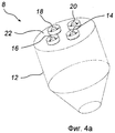
Фиг.4а представляет трехмерную проекцию распылительного сушильного абсорбера в соответствии с первым осуществлением настоящего изобретения;Fig. 4a is a three-dimensional view of a spray drying absorber in accordance with a first embodiment of the present invention;
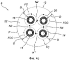
Фиг.4b представляет вид сверху распылительного сушильного абсорбера с фиг.4а;Fig. 4b is a plan view of the spray drying absorber of Fig. 4a;
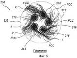
Фиг.5 представляет вид сверху следующего распылительного сушильного абсорбера в соответствии с прототипом;Figure 5 is a top view of the next spray drying absorber in accordance with the prototype;
Фиг.6 представляет вид сверху распылительного сушильного абсорбера в соответствии со вторым осуществлением настоящего изобретения;6 is a top view of a spray drying absorber in accordance with a second embodiment of the present invention;
Фиг.7 представляет вид сверху распылительного сушильного абсорбера в соответствии с третьим осуществлением настоящего изобретения;7 is a top view of a spray drying absorber in accordance with a third embodiment of the present invention;
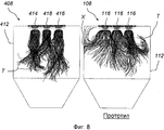
Фиг.8 представляет вид сбоку и иллюстрирует траектории капель жидкости осуществления с фиг.7 в сравнении с осуществлениями прототипа с фиг.3а и 3b;FIG. 8 is a side view and illustrates the trajectories of the liquid droplets of the implementation of FIG. 7 in comparison with the embodiments of the prototype of FIGS. 3a and 3b;
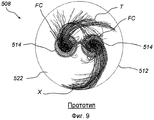
Фиг.9 представляет вид сверху еще одного распылительного сушильного абсорбера в соответствии с прототипом;Fig.9 is a top view of another spray drying absorber in accordance with the prototype;
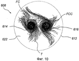
Фиг.10 представляет вид сверху распылительного сушильного абсорбера в соответствии с четвертым осуществлением настоящего изобретения;10 is a top view of a spray drying absorber in accordance with a fourth embodiment of the present invention;
Фиг.11 представляет диаграмму, показывающую количество жидкости, попадающей на стенку соответствующего распылительного сушильного абсорбера в различных осуществлениях.11 is a diagram showing the amount of liquid entering the wall of a corresponding spray drying absorber in various embodiments.
ОПИСАНИЕ ПРЕДПОЧТИТЕЛЬНЫХ ОСУЩЕСТВЛЕНИЙDESCRIPTION OF PREFERRED EMBODIMENTS
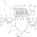
Фиг.1 представляет схематически вид сбоку и показывает силовую установку 1. Силовая установка 1 включает котел 2, в котором сжигается топливо, такое как уголь или нефть. Сгорание топлива генерирует горячий технологический газ в виде дымового газа 2. Сернистые вещества, содержащиеся в угле или нефти, будут образовывать двуокись серы, которая будет образовывать часть дымового газа. Дымовой газ поступает из котла 2 в электростатический осадитель 4 через канал 6. Электростатический осадитель 4, пример которого описан в US 4502872, служит для удаления частиц пыли из дымового газа.Figure 1 is a schematic side view and shows a
Дымовой газ, из которого удалена большая часть частиц пыли, направляют в распылительный сушильный абсорбер 8 через канал 10. Распылительный сушильный абсорбер 8 включает распылительную сушильную камеру 12 и четыре диспергатора 14, 16, 18, 20, которые смонтированы на крыше 22 распылительной сушильной камеры 12. Каждый из диспергаторов 14, 16, 18, 20 включает распылитель 24. Распылители 24 могут быть распылителями так называемого центробежного типа, в которых вращающееся с большой скоростью колесо служит для распыления поглощающей жидкости. В этом отношении в качестве пояснения, а не ограничения, может быть сделана ссылка, например, на центробежный распылитель, описанный в US 4755366, идеи которого настоящим введены сюда ссылкой. Следующей альтернативой является использование в качестве распылителей 24 распылительных форсунок, которые распыляют подаваемую в них поглощающую жидкость под давлением.Flue gas, from which most of the dust particles have been removed, is sent to the spray drying absorber 8 through the
Каждый диспергатор 14, 16, 18, 20 снабжен устройством 26, 28, 30, 32 направления потока. Распределительный канал 34 служит для снабжения каждого из диспергаторов 14, 16, 18, 20 порцией дымового газа, подаваемого по каналу 10. Каждое из устройств 26, 28, 30, 32 направления потока служит для придания соответствующей части дымового газа вращательного движения вокруг распылителя 24 соответствующего диспергатора 14, 16, 18, 20. Два из устройств направления потока, а именно направляющие 26 и 30 диспергаторов 14 и 18, служат для придания соответствующей части дымового газа, подаваемой в них, вращательного движения вокруг соответствующего распылителя 24 в направлении по часовой стрелке, если смотреть с верха распылительной сушильной камеры 12.Each
Два из устройств направления движения потока, а именно направляющие 28 и 32 диспергаторов 16 и 20 служат для придания соответствующей части дымового газа, подаваемой в них, вращательного движения вокруг соответствующего распылителя 24 в направлении против часовой стрелки, если смотреть с верха распылительной сушильной камеры 12.Two of the flow direction devices, namely the
Резервуар 36 служит для снабжения каждого из распылителей 24 потоком поглощающей жидкости через распределительный трубопровод 38; такая поглощающая жидкость включает, например, известняковую суспензию (взвесь).The
Действие соответствующих диспергаторов 14, 16, 18, 20 приводит в результате к смешению дымового газа с поглощающей жидкостью. Результатом является то, что поглощающая жидкость поглощает газообразные вредные вещества, такие как двуокись серы, SO2 из дымового газа. В то же время поглощающая жидкость высушивается горячим дымовым газом, давая в результате сухой продукт, который собирается у днища 40 распылительной сушильной камеры 12. Сухой продукт удаляют для захоронения через трубопровод 42. Дымовой газ, из которого была удалена большая часть газообразных вредных веществ, проходит практически вертикально вниз из диспергаторов 14, 16, 18, 20 в распылительную сушильную камеру 12 и покидает распылительный сушильный абсорбер 8 через канал 44. Дымовой газ направляют посредством канала 44 во второй фильтр, которым может быть, например, электростатический осадитель 46. Как альтернатива, вторым фильтром может быть рукавный фильтр или любое другое подходящее фильтрующее устройство. Второй фильтр 46 удаляет большую часть оставшихся частиц пыли и все высушенные остатки поглощающей жидкости. Очищенный дымовой газ может быть затем выпущен в окружающую атмосферу через канал чистого газа 48.The action of the
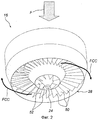
Фиг.2 показывает диспергатор 16 более подробно. Диспергатор 16 показан в виде снизу под углом. Направляющее поток устройство 28 диспергатора 16 включает множество наружных направляющих лопаток 50 и множество внутренних направляющих лопаток 52. Часть дымового газа, входящая в диспергатор 16 из распределительного канала 34, показанного на фиг.1, имеет общее нисходящее направление, как показано на фиг.2 стрелкой F. Все направляющие лопатки 50, 52 имеют такое направление, чтобы они принуждали часть дымового газа начать вращаться вокруг распылителя 24. Стрелки FCC показывают как направляющие лопатки 50, 52 будут отклонять дымовой газ так, чтобы было сформировано вращение потока дымового газа по нисходящей спирали вокруг распылителя 24. Было найдено, что такое вращение дымового газа должно быть весьма эффективно для смешения дымового газа с поглощающей жидкостью, распыленной распылителем 24. Направление вращения такого потока дымового газа FCC будет, если смотреть с верха распылительной сушильной камеры 12, показанной на фиг.1, движением против часовой стрелки для диспергатора 16.Figure 2 shows the
Должно быть ясно, что диспергатор 20 будет иметь конструкцию, подобную диспергатору 16, показанному на фиг.2. Устройства 26, 30 направления потока диспергаторов 14 и 18, показанных на фиг.1, должны, с другой стороны, иметь направляющие лопатки, которые имеют противоположную установку по сравнению с направляющими лопатками 50, 52 устройства 28 направления потока, показанного на фиг.2, так, чтобы направление вращения потока дымового газа из диспергаторов 14, 18 было, если смотреть с верха распылительной сушильной камеры 12, показанной на фиг.1, движением по часовой стрелке.It should be clear that the
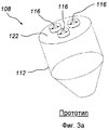
Фиг.3а показывает распылительный сушильный абсорбер 108 в соответствии с конструкцией прототипа. Этот распылительный сушильный абсорбер 108 имеет распылительную сушильную камеру 112 и крышу 122. На своей крыше распылительный сушильный абсорбер 108 снабжен тремя диспергаторами 116. Каждый из этих диспергаторов 116 имеет конструкцию, подобную диспергатору 16, описанному здесь выше со ссылкой на фиг.2. Фиг.3b показывает вид сверху распылительного сушильного абсорбера 108 в соответствии с конструкцией прототипа. Поскольку каждый из диспергаторов 116 имеет конструкцию, подобную диспергатору 16, описанному здесь выше со ссылкой на фиг.2, потоку дымового газа, подаваемого в каждый из диспергаторов 116, будет придаваться вращательное движение в направлении против часовой стрелки, если смотреть с верха распылительного сушильного абсорбера 108. Это показано на фиг.3b посредством стрелок FCC. Было, однако, найдено, что работа распылительного сушильного абсорбера 108 по прототипу, показанного на фиг.3а и 3b, приводит в результате к серьезным проблемам с попаданием поглощающей жидкости на стенку распылительной сушильной камеры 112, например, в месте Х, показанном на фиг.3b. Попадание поглощающей жидкости на стенку распылительной сушильной камеры 112 может привести в результате к образованию крупных агрегатов, вызывая затруднения в работе распылительного сушильного абсорбера 108. Кроме того, было найдено, что во время работы распылительного сушильного абсорбера 108 образуются крупные капли поглощающей жидкости. Для высыхания таких крупных капель требуется много времени. Поэтому капли, которые не полностью высохли, могут попасть на дно распылительной сушильной камеры 112 или в выходной фильтр, приводя в результате к затруднениям в работе.Figa shows a
Фиг.4а показывает распылительный сушильный абсорбер 6 в соответствии с первым осуществлением настоящего изобретения, которое было пояснено ранее со ссылками на фиг.1 и фиг.2. На фиг.4а ясно показано как распылительная сушильная камера 12 оборудована на ее крыше 22 четырьмя диспергаторами 14, 16, 18, 20.Fig. 4a shows a
Фиг.4b показывает распылительный сушильный абсорбер 8 в виде сверху. Как описано здесь выше со ссылкой на фиг.2, диспергаторы 16 и 20 придают подаваемому в них дымовому газу вращательное движение против часовой стрелки, если смотреть сверху, как показано на фиг.4b. На фиг.4b это вращение против часовой стрелки показано посредством стрелок FCC. Далее, диспергаторы 14 и 18 имеют другую конструкцию по сравнению с диспергаторами 16 и 20 и придают поступающему в них дымовому газу вращательное движение по часовой стрелке, если смотреть с верха, как показано на фиг.4b. На фиг.4b это вращение по часовой стрелке показано посредством стрелок FC.Fig. 4b shows a
Каждый из диспергаторов 14, 16, 18, 20 расположен на практически одинаковом расстоянии D от периферии Р распылительной сушильной камеры 12. Рассматривая диспергатор 16, направляющее движение потока устройство этого диспергатора, обозначенное как 50 и 52 и показанное подробно на фиг.2, служит для придания части дымового газа, проходящей через этот определенный диспергатор 16, вращательного движения в направлении против часовой стрелки, если смотреть сверху, которое противоположно направлению вращательного движения по часовой стрелке, если смотреть сверху, соответствующих частей дымового газа, диспергируемых двумя диспергаторами 14 и 18, расположенными наиболее близко, если смотреть по периферии Р распылительной сушильной камеры 12, к этому определенному диспергатору 16. Подобным образом диспергатор 14, придающий подаваемой через него части топливного газа вращательное движение по часовой стрелке, если смотреть сверху, имеет своими ближайшими "соседями" два диспергатора, 16 и 20, которые придают дымовому газу вращательное движение против часовой стрелки. Как следствие, каждый из диспергаторов 14, 16, 18, 20 имеет своими ближайшими "соседями" два диспергатора, которые придают дымовому газу противоположное направление движения по сравнению с вращательным движением, придаваемым дымовому газу этим определенным диспергатором.Each of the
В качестве примера, в точке N1, где диспергаторы 14 и 16 расположены ближе всего друг к другу, поля потока от обоих диспергаторов 14 и 16 будут иметь одинаковое направление. Подобное поведение потока будет воспроизводиться и в точках N2, N3 и N4. Следовательно, для всех четырех точек N1, N2, N3, N4, где поля потоков двух смежных диспергаторов 14, 16, 18, 20 могут взаимодействовать, поля потоков этих двух диспергаторов всегда будут иметь одинаковое направление в отличие от конструкции прототипа показанной на фиг.3а и фиг.3b.As an example, at point N1, where
Конструкция, показанная на фиг.4а и 4b, по-видимому создает ситуацию, где число столкновений между каплями жидкости, произошедших из любых двух соседних диспергаторов, намного уменьшено. Результатом является уменьшение образования больших капель по сравнению с прототипом, показанным на фиг.3а и 3b, Далее, в распылительном сушильном абсорбере 8, показанном на фиг.4а и 4b, вращательное движение дымового газа, вызванное диспергаторами 14, 16, 18, 20, по-видимому продолжается в течение более длительного времени, приводя в результате к улучшенному контакту между каплями поглощающей жидкости и дымовым газом; такой улучшенный контакт приводит в результате к улучшенному удалению газообразных вредных веществ и к более короткому времени сушки капель жидкости. Риск образования крупных агрегатов на стенке распылительной сушильной камеры 12 также по-видимому уменьшается по сравнению с конструкцией прототипа.The design shown in FIGS. 4a and 4b appears to create a situation where the number of collisions between liquid droplets originating from any two adjacent dispersants is greatly reduced. The result is a reduction in the formation of large droplets compared to the prototype shown in FIGS. 3a and 3b. Further, in the
Фиг.5 показывает распылительный сушильный абсорбер 208 в соответствии с еще одной конструкцией прототипа. Распылительный сушильный абсорбер 208 имеет распылительную сушильную камеру 212 и крышу 222. На своей крыше 222 распылительный сушильный абсорбер 208 оборудован пятью диспергаторами 216. Каждый из этих диспергаторов 216 будет иметь конструкцию, подобную диспергатору 16, описанному здесь ранее со ссылкой на фиг.1, следовательно, конструкцию, подобную диспергатору 16, описанному здесь выше со ссылкой на фиг.2. Пять диспергаторов 216 размещены в соответствии с аналогичными принципами, как три диспергатора 116 распылительного сушильного абсорбера 108. Как следствие, дымовому газу, подаваемому в каждый из пяти диспергаторов 216, будет придаваться вращательное движение в направлении против часовой стрелки, если смотреть с верха распылительного сушильного абсорбера, обозначенное на фиг.5 как FCC. В фиг.5 были включены также траектории капель Т, показанные как линии, начинающиеся от соответствующих диспергаторов 216. Эти траектории Т показывают пути, проходимые отдельными каплями распыленной жидкости в течение одной секунды после того, как они покинут соответствующий распылитель соответствующего диспергатора 216, описанного здесь выше со ссылкой на фиг.2. Траектории Т основаны на компьютерных гидроаэродинамических расчетах. Конец траектории указывает место, в котором почти вся жидкость оказывается высушенной. Из фиг.6 можно видеть, что траектории Т попадают на стенку распылительной сушильной камеры 212, в особенности в местах, обозначенных буквой Х. Это показывает, что капли, которые не высохли, попадают на стенку распылительной сушильной камеры 212 в этих местах, что может привести в результате к образованию агрегатов, вызывающему большие затруднения в работе распылительного сушильного абсорбера 208.5 shows a
Фиг.6 показывает распылительный сушильный абсорбер 308 в соответствии со вторым осуществлением настоящего изобретения в виде сверху. Как можно видеть, распылительный сушильный абсорбер 308 имеет распылительную сушильную камеру 312, имеющую крышу 322. Крыша 322 оборудована пятью диспергаторами 314, 316, 318, 320 и 321, расположенные на одинаковых расстояниях от периферии камеры 312. Как следствие, и как можно видеть из фиг.6, пять диспергаторов 314, 316, 318, 320 и 321 расположены по кольцу. Первый диспергатор 314 и четвертый диспергатор 320, если смотреть по периферии камеры 312, установлены, чтобы придать поступающему в них дымовому газу направление вращения по часовой стрелке, показанное на фиг.6 символом FC. Второй диспергатор 316, третий диспергатор 318 и пятый диспергатор 321 установлены, чтобы придать поступающему в них дымовому газу направление вращения против часовой стрелки, показанное на фиг.6 символом FCC. Следовательно, диспергаторы 316, 318 и 321 сконструированы подобно диспергатору 16, показанному подробно на фиг.2, в то время как диспергаторы 314 и 320 имеют направляющие лопатки, имеющие противоположную установку для придания дымовому газу противоположного направления вращения, подобно диспергатору 14, описанному со ссылкой на фиг.1.6 shows a
Следовательно, при конструкции как на фиг.6, максимум два идущих друг за другом, если смотреть по периферии распылительной сушильной камеры 312, диспергатора, а именно, диспергаторы 316 и 318, придают подаваемому в них дымовому газу вращательное движение в одном и том же направлении FCC.Therefore, with the design as in FIG. 6, a maximum of two consecutive, when viewed around the periphery of the spray drying chamber 312, the dispersant, namely the dispersant 316 and 318, give the flue gas supplied to them a rotational movement in the same direction FCC
На фиг.6 траектории Т показывают расчетные пути капель жидкости в течение одной секунды после того, как они покинут соответствующий распылитель 24 соответствующего диспергатора 314, 316, 318, 320 и 321. Как можно видеть из фиг 6, ни одна траектория не попадает на стенку распылительной сушильной камеры 312. Следовательно, при таком размещении будет намного меньше проблем с образованием агрегатов.In Fig. 6, the trajectories T show the calculated paths of the liquid droplets within one second after they leave the corresponding
Фиг.7 показывает распылительный сушильный абсорбер 408 в соответствии с третьим осуществлением настоящего изобретения в виде сверху. Как можно видеть, распылительный сушильный абсорбер 408 имеет распылительную сушильную камеру 412, имеющую крышу 422. Крыша 422 оборудована тремя диспергаторами 414, 416 и 418. Как можно видеть из фиг.7, три диспергатора 414, 416 и 418 расположены подобно трем диспергаторам 116 распылительного сушильного абсорбера 108 по прототипу, показанному здесь ранее со ссылкой на фиг.3а и фиг.3b. Однако, возвращаясь к фиг.7, первый диспергатор 414 и второй диспергатор 416 устроены так, чтобы придать поступающему в них дымовому газу направление вращения против часовой стрелки, показанное на фиг.7 символом FCC. Третий диспергатор 418 устроен, чтобы придать поступающему в него дымовому газу направление вращения по часовой стрелке, показанное на фиг.7 символом FC. Следовательно, диспергаторы 414 и 416 сконструированы подобно диспергатору 16, показанному подробно на фиг.2, в то время как диспергатор 418 имеет направляющие лопатки, имеющие противоположную установку для придания дымовому газу противоположного направления вращения, подобно диспергатору 14, описанному со ссылкой на фиг.1.7 shows a
Фиг.8 показывает работу распылительного сушильного абсорбера 408, описанного со ссылкой на фиг.7, в сравнении с работой распылительного сушильного абсорбера 108 по прототипу, описанного со ссылкой на фиг.3a и 3b. Траектории Т показывают расчетные пути отдельных капель распыленной жидкости в течение одной секунды после того, как они покинут соответствующий распылитель 24 соответствующего диспергатора 414, 416, 418 и 116, соответственно, распылительных сушильных абсорберов 408 и 108, где распылительные сушильные абсорберы 408 и 108,показаны на фиг.8 в виде сбоку. Как можно видеть, обращаясь к фиг.8, траектории Т распылительного сушильного абсорбера 408 все предпочтительно собираются к центру распылительной сушильной камеры 412. Как следствие, проблемы капель жидкости, попадающих на стенку и образующих агрегаты в распылительном сушильном абсорбере 408 сильно ограничены. С другой стороны, траектории Т, сформированные в распылительном сушильном абсорбере 108 по прототипу, являются намного более беспорядочными, и существенная часть капель попадает на стенки распылительной сушильной камеры 112, например, в месте Х, где вероятно возникновение твердых агрегатов. Как следствие, можно ожидается, что распылительный сушильный абсорбер 408 обеспечивает намного более устойчивую работу с меньшими эксплуатационными проблемами, чем распылительный сушильный абсорбер 108 по прототипу.FIG. 8 shows the operation of the
Фиг.9 показывает распылительный сушильный абсорбер 508 в соответствии с еще одной конструкцией прототипа. Распылительный сушильный абсорбер 508 имеет распылительную сушильную камеру 512 и крышу 522. На своей крыше 522 распылительный сушильный абсорбер 508 оборудован двумя диспергаторами 514. Каждый из этих диспергаторов 514 будет иметь конструкцию, подобную диспергатору 14, описанному здесь ранее со ссылкой на фиг.1, следовательно, конструкцию, подобную диспергатору 16, показанному на фиг.2, но с направляющими лопатками, имеющими противоположную установку. Эти два диспергатора 514 расположены симметрично вокруг центра крыши 522 и, следовательно, одинаковых расстояниях от периферии распылительной сушильной камеры 512. Дымовому газу, подаваемому в каждый из двух диспергаторов 514, будет придаваться вращательное движение по направлению часовой стрелки, показанное на фиг.9 как FC, если смотреть с верха распылительного сушильного абсорбера 508. Траектории Т показывают пути, проходимые отдельными каплями распыленной жидкости в течение одной секунды после того, как они покинут соответствующий распылитель соответствующего диспергатора 514, после этой одной секунды почти вся жидкость будет высушена дымовым газом. Траектории Т основаны на компьютерных гидроаэродинамических расчетах. Из фиг.9 можно видеть, что траектории Т попадают на стенку распылительной сушильной камеры 512, в особенности в месте, обозначенном буквой Х. Это может привести в результате к образованию агрегатов, вызывающему большие затруднения в работе распылительного сушильного абсорбера 508.Figure 9 shows a
Фиг.10 показывает распылительный сушильный абсорбер 608 в соответствии с четвертым осуществлением настоящего изобретения в виде сверху. Как можно видеть, распылительный сушильный абсорбер 608 имеет распылительную сушильную камеру 612, имеющую крышу 622. Крыша 622 оборудована двумя диспергаторами 614 и 616. Как можно видеть на фиг.10, два диспергатора 614, 616 расположены симметрично вокруг центра крыши 622 и на одинаковом расстоянии от периферии стенки камеры 612. Первый диспергатор 614 устроен так, чтобы придать поступающему в него газу направление вращения по часовой стрелке, показанное обозначением FC на фиг.10. Второй диспергатор 616 устроен так, чтобы придать поступающему в него газу направление вращения против часовой стрелки, показанное обозначением FCC на фиг.10. Как следствие, диспергатор 616 сконструирован подобно диспергатору 16, показанному подробно на фиг.2, тогда как диспергатор 614 имеет направляющие лопатки, имеющие противоположную установку, чтобы придать дымовому газу противоположное направление вращения, подобно диспергатору 14, описанному со ссылкой на фиг.1.Figure 10 shows a
Траектории Т показывают расчетные пути капель жидкости в течение одной секунды после того, как они покинут соответствующий распылитель 24 соответствующего диспергатора 614 или 616, после этой одной секунды почти вся жидкость будет высушена дымовым газом. Как можно видеть из фиг 10, ни одна траектория не попадает на стенку распылительной сушильной камеры 612. Следовательно, при таком размещении будет намного меньше проблем с образованием агрегатов на стенке по сравнению с осуществлением прототипа на фиг.8.The trajectories T show the calculated paths of the liquid droplets within one second after they leave the corresponding
Фиг.11 представляет столбчатую диаграмму, показывающую количество распыленной жидкости, воды, попадающей на стенку распылительной сушильной камеры в различных осуществлениях. Следовательно, для каждого осуществления столбик показывает количество воды (в кг/с) из распыленной жидкости, попадающей на стенку распылительной сушильной камеры, рассчитанное посредством компьютерных гидродинамических расчетов. Чем ниже количество воды, попадающей на стенку, тем меньше риск образования на стенке агрегатов.11 is a bar graph showing the amount of sprayed liquid, water entering the wall of the spray drying chamber in various embodiments. Therefore, for each implementation, the column shows the amount of water (in kg / s) from the sprayed liquid falling on the wall of the spray drying chamber, calculated by computer-assisted hydrodynamic calculations. The lower the amount of water entering the wall, the lower the risk of aggregates forming on the wall.
Из фиг.11 можно видеть, что распылительный сушильный абсорбер 508 по прототипу, имеющий два диспергатора 514, как показано на фиг.9, генерирует поток в примерно 0,125 кг/с воды, ударяющийся о стенки распылительной сушильной камеры 512, в то время как распылительный сушильный абсорбер 608, имеющий два диспергатора 614, 616, как показано на фиг.10, генерирует поток только в примерно 0,035 кг/с воды, ударяющийся о стенки распылительной сушильной камеры 612, составляя только 28% от количества в распылительной сушилке 508 по прототипу.From FIG. 11, it can be seen that the
Далее, распылительный сушильный абсорбер 108 по прототипу, имеющий три диспергатора 116, как показано на фиг.3b, генерирует поток в примерно 0,130 кг/с воды, ударяющийся о стенки распылительной сушильной камеры 112, в то время как распылительный сушильный абсорбер 408, имеющий три диспергатора 414, 416, 418, как показано на фиг.7, генерирует поток только в примерно 0,07 кг/с воды, ударяющийся о стенки распылительной сушильной камеры 412, составляя только 54% от количества в распылительной сушилке 108 по прототипу.Further, the
Далее, были сделаны также расчеты для распылительного сушильного абсорбера 708 по прототипу, имеющему четыре диспергатора. Распылительный сушильный абсорбер 708 по прототипу не был показан подробно, но имел конструкцию, подобную распылительному сушильному абсорберу 8, показанному со ссылкой на фиг.4b, за исключением того факта, что все четыре диспергатора распылительного сушильного абсорбера 708 по прототипу придавали поступающему в них дымовому газу противоточное направление движения. Распылительный сушильный абсорбер 708 по прототипу, имеющий четыре противоточно направленных диспергатора, генерирует поток в примерно 0,08 кг/с воды, ударяющийся о стенки распылительной сушильной камеры, в то время как распылительный сушильный абсорбер 8, имеющий четыре диспергатора 14, 16, 18, 20, как показано на фиг.4b, генерирует поток только в примерно 0,015 кг/с воды, ударяющийся о стенки распылительной сушильной камеры 12, составляя только 19% от количества в распылительной сушилке 708 по прототипу.Further, calculations were also made for the
Наконец, распылительный сушильный абсорбер 208 по прототипу, имеющий пять диспергаторов, как показано на фиг.5, генерирует поток в примерно 0,205 кг/с воды, ударяющийся о стенки распылительной сушильной камеры 212, в то время как распылительный сушильный абсорбер 308, имеющий пять диспергаторов 314, 316, 318, 320 и 321, как показано на фиг.6, генерирует поток только в примерно 0,015 кг/с воды, ударяющийся о стенки распылительной сушильной камеры 412, составляя только 7% от количества в распылительной сушилке 208 по прототипу.Finally, the
Следовательно, для каждого конкретного числа диспергаторов распылительного сушильного абсорбера неожиданно намного лучше в отношении риска образования агрегатов на стенках распылительной сушильной камеры размещать эти диспергаторы в соответствии с принципами настоящего изобретения по сравнению с размещением их согласно прототипу.Therefore, for each specific number of spray drying absorber dispersants, it is unexpectedly much better with respect to the risk of aggregation on the walls of the spray drying chamber to place these dispersants in accordance with the principles of the present invention compared to placing them according to the prototype.
Должно быть ясно, что многочисленные модификации описанных выше осуществлений возможны в рамках объема прилагаемой формулы изобретения.It should be clear that numerous modifications of the above embodiments are possible within the scope of the attached claims.
Выше было описано, что распылительный сушильный абсорбер 8, 308, 408, 608 может быть снабжен 2, 3, 4 или 5 диспергаторами. Должно быть ясно, что такой же эффект может быть достигнут с другим количеством диспергаторов от двух и более, расположенных на таком же расстоянии D от периферии Р распылительной сушильной камеры 12. Обычно распылительный сушильный абсорбер, спроектированный в соответствии с настоящим изобретением, должен иметь от 2 до 9 диспергаторов, расположенных на практически одинаковом расстоянии D от периферии Р распылительной сушильной камеры.It has been described above that the
Выше было описано, что в распылительном сушильном абсорбере, имеющем по меньшей мере три диспергатора, предпочтительно, чтобы максимум два идущих друг за другом диспергатора из этих по меньшей мере трех диспергаторов работали для придания поступающему в них дымовому газу вращательного движения в одинаковом направлении. Следовательно, в распылительном сушильном абсорбере, имеющем пять диспергаторов и спроектированном в соответствии со следующим осуществлением настоящего изобретения, должно быть возможно, в качестве примера, иметь четыре из этих диспергаторов, придающими газу вращение против часовой стрелки (FCC), и только один диспергатор, придающий газу вращение по часовой стрелке (FC), или, в качестве следующего примера, иметь три следующих друг за другом диспергатора, придающих газу вращение против часовой стрелки (FCC), и два следующих друг за другом диспергатора, придающих газу вращение по часовой стрелке (FC). Однако эти альтернативные осуществления обычно менее предпочтительны, чем те, которые показаны на фиг.6, где максимум два диспергатора, т.е. диспергаторы 316 и 318 придают подаваемому в них газу вращательное движение в одинаковом направлении, FCC.It has been described above that in a spray drying absorber having at least three dispersants, it is preferable that a maximum of two consecutive dispersants of these at least three dispersants work to give the incoming flue gas rotational motion in the same direction. Therefore, in a spray drying absorber having five dispersants and designed in accordance with the following embodiment of the present invention, it should be possible, by way of example, to have four of these dispersants giving the gas counterclockwise rotation (FCC) and only one dispersant giving gas clockwise rotation (FC), or, as a further example, have three consecutive dispersants giving the gas counterclockwise rotation (FCC), and two consecutive a gas-driven rotator (FC). However, these alternative embodiments are generally less preferred than those shown in FIG. 6, where at most two dispersants, i.e. dispersants 316 and 318 give the gas supplied to them a rotational movement in the same direction, FCC.
Суммируя, распылительный сушильный абсорбер служит для удаления газообразных вредных веществ из горячего технологического газа и включает по меньшей мере два диспергатора. Каждый такой диспергатор служит для диспергирования части горячего технологического газа вокруг соответствующего распылителя и для придания соответствующей части горячего технологического газа вращательного движения вокруг распылителя. По меньшей мере один определенный диспергатор служит для придания проходящему через этот определенный диспергатор газу горячего процесса вращательного движения в направлении, которое противоположно направлению вращательного движения соответствующей части горячего технологического газа, диспергируемой по меньшей мере одним другим диспергатором, расположенным наиболее близко к этому определенному диспергатору.Summarizing, the spray dryer absorber serves to remove gaseous harmful substances from the hot process gas and includes at least two dispersants. Each such dispersant serves to disperse a portion of the hot process gas around a respective atomizer and to impart a rotational movement around the atomizer to the corresponding portion of the hot process gas. At least one specific dispersant serves to impart a hot rotational process gas passing through this specific dispersant in a direction that is opposite to the rotational direction of the corresponding portion of the hot process gas dispersed by at least one other dispersant located closest to that particular dispersant.
Хотя изобретение было описано со ссылкой на ряд предпочтительных осуществлений, специалисту должно быть понятно, что могут быть сделаны разнообразные изменения и их элементы могут быть заменены эквивалентами без отклонения от объема изобретения. Кроме того, могут быть сделаны многие модификации для того, чтобы приспособить конкретную ситуацию или конкретный материал к идеям и изобретения без отклонения от его основной сферы. Поэтому подразумевается, что изобретение не является ограниченным конкретными осуществлениями, раскрытыми как наилучший способ, предлагаемый для реализации изобретения, но изобретение должно включать все осуществления, попадающие в объем прилагаемой формулы изобретения. Кроме того, использование терминов "первый", "второй" и т.д. не обозначает какой-либо порядок важности, а скорее термины "первый", "второй" и т.д. использованы для того, чтобы отличить один элемент от другого.Although the invention has been described with reference to a number of preferred embodiments, one skilled in the art will appreciate that various changes can be made and their elements replaced by equivalents without departing from the scope of the invention. In addition, many modifications can be made in order to adapt a specific situation or specific material to ideas and inventions without deviating from its main scope. Therefore, it is understood that the invention is not limited to the specific implementations disclosed as the best method proposed for implementing the invention, but the invention should include all implementations falling within the scope of the attached claims. In addition, the use of the terms "first", "second", etc. does not mean any order of importance, but rather the terms "first", "second", etc. used to distinguish one element from another.
Claims (6)
Applications Claiming Priority (3)
| Application Number | Priority Date | Filing Date | Title |
|---|---|---|---|
| EP08151663.5 | 2008-02-20 | ||
| EP08151663A EP2098278B1 (en) | 2008-02-20 | 2008-02-20 | A spray dryer absorber disperser arrangement. |
| PCT/EP2009/000638 WO2009103407A1 (en) | 2008-02-20 | 2009-01-30 | A spray dryer absorber disperser arrangement |
Publications (2)
| Publication Number | Publication Date |
|---|---|
| RU2010138605A RU2010138605A (en) | 2012-03-27 |
| RU2494792C2 true RU2494792C2 (en) | 2013-10-10 |
Family
ID=39608211
Family Applications (1)
| Application Number | Title | Priority Date | Filing Date |
|---|---|---|---|
| RU2010138605/02A RU2494792C2 (en) | 2008-02-20 | 2009-01-30 | Disperser of sprayer-drier absorber |
Country Status (16)
| Country | Link |
|---|---|
| US (1) | US20100319538A1 (en) |
| EP (2) | EP2098278B1 (en) |
| JP (1) | JP2011512251A (en) |
| KR (1) | KR101144701B1 (en) |
| CN (1) | CN101952013B (en) |
| AR (1) | AR070619A1 (en) |
| AT (1) | ATE528061T1 (en) |
| AU (1) | AU2009217042B2 (en) |
| BR (1) | BRPI0907759A2 (en) |
| CA (1) | CA2715705C (en) |
| CL (1) | CL2009000378A1 (en) |
| ES (1) | ES2375239T3 (en) |
| MX (1) | MX2010008212A (en) |
| PL (2) | PL2098278T3 (en) |
| RU (1) | RU2494792C2 (en) |
| WO (1) | WO2009103407A1 (en) |
Cited By (1)
| Publication number | Priority date | Publication date | Assignee | Title |
|---|---|---|---|---|
| RU2846864C2 (en) * | 2022-08-08 | 2025-09-17 | Сакми Кооператива Мекканики Имола Сочиета Кооператива | Spray drier for producing finely dispersed ceramic powder from an aqueous suspension of ceramic material |
Families Citing this family (11)
| Publication number | Priority date | Publication date | Assignee | Title |
|---|---|---|---|---|
| PL2143476T3 (en) * | 2008-07-10 | 2012-07-31 | General Electric Technology Gmbh | A disperser arrangement for a spray dryer absorber |
| KR101251503B1 (en) | 2010-12-01 | 2013-04-05 | 현대자동차주식회사 | Shifting apparatus for manual transmission |
| US9289790B2 (en) | 2014-01-13 | 2016-03-22 | Alstom Technology Ltd | Spray dryer absorber vibrator device and method |
| US9403123B2 (en) * | 2014-06-24 | 2016-08-02 | Alstom Technology Ltd | High rotational momentum disperser and use |
| JP6666231B2 (en) * | 2016-11-14 | 2020-03-13 | 三菱日立パワーシステムズ株式会社 | Spray drying system |
| KR101929928B1 (en) | 2017-01-17 | 2018-12-18 | 주식회사 지에스나노셀 | Drying apparatus for nano-cellulose |
| CN107596901A (en) * | 2017-11-10 | 2018-01-19 | 贵州红太阳环保厂 | A kind of absorption tower and multistage absorption system |
| KR102458355B1 (en) | 2020-04-02 | 2022-10-25 | 주식회사 지에스나노셀 | Nanocellulose concentration and condensation system |
| CN113479960A (en) * | 2021-07-26 | 2021-10-08 | 南方电网电力科技股份有限公司 | Spray drying tower |
| CN117959893A (en) * | 2024-03-19 | 2024-05-03 | 贵州开阳磷城磷化工有限公司 | A device for recovering high-purity phosphorus vapor |
| CN119457112A (en) * | 2025-01-14 | 2025-02-18 | 江西悦安新材料股份有限公司 | A carbonyl iron powder atomization pyrolysis device with an atomization nozzle structure |
Citations (6)
| Publication number | Priority date | Publication date | Assignee | Title |
|---|---|---|---|---|
| US4452765A (en) * | 1980-07-30 | 1984-06-05 | The Babcock & Wilcox Company | Method for removing sulfur oxides from a hot gas |
| US4755366A (en) * | 1985-02-04 | 1988-07-05 | A/S Niro Atomizer | Process for cleaning hot waste gas occuring in varying amounts |
| RU2001661C1 (en) * | 1991-07-02 | 1993-10-30 | Юрий Аркадиевич Головачевский | Slotted sprayer |
| US5639430A (en) * | 1994-10-07 | 1997-06-17 | The Babcock & Wilcox Company | Low pressure drop, turbulent mixing zone dry scrubber |
| RU2240976C1 (en) * | 2003-09-22 | 2004-11-27 | Открытое акционерное общество "Научно-исследовательский институт по удобрениям и инсектофунгицидам им. проф. Я.В.Самойлова" | Absorption tower |
| RU2304017C2 (en) * | 2005-08-11 | 2007-08-10 | Открытое Акционерное Общество "Корпорация Всмпо-Ависма" | Treatment process involving removal of chlorine and hydrogen chloride and relevant apparatus |
Family Cites Families (6)
| Publication number | Priority date | Publication date | Assignee | Title |
|---|---|---|---|---|
| US4502872A (en) | 1983-03-31 | 1985-03-05 | Combustion Engineering, Inc. | Discharge electrode wire assembly for electrostatic precipitator |
| US4519990A (en) | 1983-05-24 | 1985-05-28 | Rockwell International Corporation | Spray dryer for the purification of a gas |
| DE3508260A1 (en) * | 1985-03-08 | 1986-09-18 | Heinz Dipl.-Ing. 4390 Gladbeck Hölter | Spray absorber |
| JPH04929Y2 (en) * | 1987-11-04 | 1992-01-13 | ||
| DE19651074A1 (en) * | 1996-12-09 | 1998-06-10 | Abb Research Ltd | Sulphur removal from flue gas |
| PL2143476T3 (en) * | 2008-07-10 | 2012-07-31 | General Electric Technology Gmbh | A disperser arrangement for a spray dryer absorber |
-
2008
- 2008-02-20 EP EP08151663A patent/EP2098278B1/en not_active Not-in-force
- 2008-02-20 ES ES08151663T patent/ES2375239T3/en active Active
- 2008-02-20 AT AT08151663T patent/ATE528061T1/en not_active IP Right Cessation
- 2008-02-20 PL PL08151663T patent/PL2098278T3/en unknown
-
2009
- 2009-01-30 JP JP2010547076A patent/JP2011512251A/en active Pending
- 2009-01-30 AU AU2009217042A patent/AU2009217042B2/en not_active Ceased
- 2009-01-30 PL PL09711598T patent/PL2257361T3/en unknown
- 2009-01-30 CA CA2715705A patent/CA2715705C/en not_active Expired - Fee Related
- 2009-01-30 BR BRPI0907759-6A patent/BRPI0907759A2/en not_active Application Discontinuation
- 2009-01-30 RU RU2010138605/02A patent/RU2494792C2/en not_active IP Right Cessation
- 2009-01-30 MX MX2010008212A patent/MX2010008212A/en active IP Right Grant
- 2009-01-30 KR KR1020107019910A patent/KR101144701B1/en not_active Expired - Fee Related
- 2009-01-30 WO PCT/EP2009/000638 patent/WO2009103407A1/en not_active Ceased
- 2009-01-30 EP EP09711598.4A patent/EP2257361B1/en not_active Not-in-force
- 2009-01-30 CN CN200980106561.7A patent/CN101952013B/en not_active Expired - Fee Related
- 2009-01-30 US US12/867,574 patent/US20100319538A1/en not_active Abandoned
- 2009-02-19 CL CL2009000378A patent/CL2009000378A1/en unknown
- 2009-02-20 AR ARP090100602A patent/AR070619A1/en not_active Application Discontinuation
Patent Citations (6)
| Publication number | Priority date | Publication date | Assignee | Title |
|---|---|---|---|---|
| US4452765A (en) * | 1980-07-30 | 1984-06-05 | The Babcock & Wilcox Company | Method for removing sulfur oxides from a hot gas |
| US4755366A (en) * | 1985-02-04 | 1988-07-05 | A/S Niro Atomizer | Process for cleaning hot waste gas occuring in varying amounts |
| RU2001661C1 (en) * | 1991-07-02 | 1993-10-30 | Юрий Аркадиевич Головачевский | Slotted sprayer |
| US5639430A (en) * | 1994-10-07 | 1997-06-17 | The Babcock & Wilcox Company | Low pressure drop, turbulent mixing zone dry scrubber |
| RU2240976C1 (en) * | 2003-09-22 | 2004-11-27 | Открытое акционерное общество "Научно-исследовательский институт по удобрениям и инсектофунгицидам им. проф. Я.В.Самойлова" | Absorption tower |
| RU2304017C2 (en) * | 2005-08-11 | 2007-08-10 | Открытое Акционерное Общество "Корпорация Всмпо-Ависма" | Treatment process involving removal of chlorine and hydrogen chloride and relevant apparatus |
Cited By (1)
| Publication number | Priority date | Publication date | Assignee | Title |
|---|---|---|---|---|
| RU2846864C2 (en) * | 2022-08-08 | 2025-09-17 | Сакми Кооператива Мекканики Имола Сочиета Кооператива | Spray drier for producing finely dispersed ceramic powder from an aqueous suspension of ceramic material |
Also Published As
| Publication number | Publication date |
|---|---|
| RU2010138605A (en) | 2012-03-27 |
| EP2257361A1 (en) | 2010-12-08 |
| WO2009103407A1 (en) | 2009-08-27 |
| US20100319538A1 (en) | 2010-12-23 |
| EP2098278B1 (en) | 2011-10-12 |
| KR20100121640A (en) | 2010-11-18 |
| AR070619A1 (en) | 2010-04-21 |
| EP2257361B1 (en) | 2017-03-29 |
| AU2009217042B2 (en) | 2012-02-23 |
| ATE528061T1 (en) | 2011-10-15 |
| CN101952013A (en) | 2011-01-19 |
| EP2098278A1 (en) | 2009-09-09 |
| CL2009000378A1 (en) | 2010-09-21 |
| PL2098278T3 (en) | 2012-03-30 |
| AU2009217042A1 (en) | 2009-08-27 |
| MX2010008212A (en) | 2010-09-30 |
| PL2257361T3 (en) | 2017-09-29 |
| ES2375239T3 (en) | 2012-02-28 |
| BRPI0907759A2 (en) | 2015-07-21 |
| KR101144701B1 (en) | 2012-05-24 |
| JP2011512251A (en) | 2011-04-21 |
| CA2715705A1 (en) | 2009-08-27 |
| CN101952013B (en) | 2014-01-08 |
| CA2715705C (en) | 2013-04-09 |
Similar Documents
| Publication | Publication Date | Title |
|---|---|---|
| RU2494792C2 (en) | Disperser of sprayer-drier absorber | |
| CN102089064B (en) | Disperser Arrangement for Spray Dryer Absorber | |
| EP2959960B1 (en) | High rotational momentum disperser and use | |
| KR101992290B1 (en) | Semi dry reactor enhancing SOx removal efficiency by improving a gas flow pattern | |
| CA2929106C (en) | Device and method for heat and mass exchange between gas and liquid | |
| CN103338841A (en) | A wet scrubber and a method of cleaning a process gas | |
| KR20160049782A (en) | Scrubber | |
| CN102089063B (en) | Spray dryer absorption process for flue gas with entrained coarse particles | |
| KR20190090735A (en) | Semi dry reactor enhancing SOx removal efficiency by improving a gas flow pattern | |
| US9227157B2 (en) | Spray dryer absorption apparatus with flat-bottomed chamber | |
| JP2006122862A (en) | Apparatus for treating exhaust gas | |
| CN205988640U (en) | The charged ultrapurification plant of mist formula | |
| JP7524308B2 (en) | Absorption tower of desulfurization equipment | |
| CN105833710A (en) | Centrifugal reaction tower | |
| CN206508792U (en) | A kind of dust arrester of utilization dry fog technology | |
| CN110255651B (en) | A double U-stroke wastewater spray drying tower | |
| CN113443674A (en) | Spray drying tower | |
| WO2025258129A1 (en) | Dust collector | |
| JPH09308816A (en) | Exhaust gas treatment method |
Legal Events
| Date | Code | Title | Description |
|---|---|---|---|
| PD4A | Correction of name of patent owner | ||
| MM4A | The patent is invalid due to non-payment of fees |
Effective date: 20180131 |