RU2490820C2 - Receiver apparatus and communication method - Google Patents
Receiver apparatus and communication method Download PDFInfo
- Publication number
- RU2490820C2 RU2490820C2 RU2010112602/07A RU2010112602A RU2490820C2 RU 2490820 C2 RU2490820 C2 RU 2490820C2 RU 2010112602/07 A RU2010112602/07 A RU 2010112602/07A RU 2010112602 A RU2010112602 A RU 2010112602A RU 2490820 C2 RU2490820 C2 RU 2490820C2
- Authority
- RU
- Russia
- Prior art keywords
- cqi
- subband
- cqi index
- index
- frequency
- Prior art date
Links
- 238000004891 communication Methods 0.000 title claims abstract description 20
- 238000000034 method Methods 0.000 title claims description 15
- 238000005259 measurement Methods 0.000 claims abstract description 107
- 241001538234 Nala Species 0.000 claims 1
- 239000000284 extract Substances 0.000 abstract description 6
- 239000000126 substance Substances 0.000 abstract 1
- 238000012545 processing Methods 0.000 description 23
- 238000013468 resource allocation Methods 0.000 description 21
- 101000741965 Homo sapiens Inactive tyrosine-protein kinase PRAG1 Proteins 0.000 description 15
- 102100038659 Inactive tyrosine-protein kinase PRAG1 Human genes 0.000 description 15
- 238000010586 diagram Methods 0.000 description 12
- 230000005540 biological transmission Effects 0.000 description 11
- 230000001419 dependent effect Effects 0.000 description 8
- 238000006243 chemical reaction Methods 0.000 description 7
- 238000005516 engineering process Methods 0.000 description 5
- 125000002306 tributylsilyl group Chemical group C(CCC)[Si](CCCC)(CCCC)* 0.000 description 4
- 230000003044 adaptive effect Effects 0.000 description 3
- 238000004364 calculation method Methods 0.000 description 3
- 239000011159 matrix material Substances 0.000 description 3
- 238000012544 monitoring process Methods 0.000 description 3
- ATJFFYVFTNAWJD-UHFFFAOYSA-N Tin Chemical compound [Sn] ATJFFYVFTNAWJD-UHFFFAOYSA-N 0.000 description 2
- 238000001514 detection method Methods 0.000 description 2
- 230000006978 adaptation Effects 0.000 description 1
- 230000006835 compression Effects 0.000 description 1
- 238000007906 compression Methods 0.000 description 1
- 230000007274 generation of a signal involved in cell-cell signaling Effects 0.000 description 1
- 230000010354 integration Effects 0.000 description 1
- 230000007774 longterm Effects 0.000 description 1
- 238000004519 manufacturing process Methods 0.000 description 1
- 238000010295 mobile communication Methods 0.000 description 1
- 239000004065 semiconductor Substances 0.000 description 1
- 238000001228 spectrum Methods 0.000 description 1
Images
Classifications
-
- H—ELECTRICITY
- H04—ELECTRIC COMMUNICATION TECHNIQUE
- H04L—TRANSMISSION OF DIGITAL INFORMATION, e.g. TELEGRAPHIC COMMUNICATION
- H04L1/00—Arrangements for detecting or preventing errors in the information received
- H04L1/0001—Systems modifying transmission characteristics according to link quality, e.g. power backoff
- H04L1/0023—Systems modifying transmission characteristics according to link quality, e.g. power backoff characterised by the signalling
- H04L1/0028—Formatting
- H04L1/0029—Reduction of the amount of signalling, e.g. retention of useful signalling or differential signalling
-
- H—ELECTRICITY
- H04—ELECTRIC COMMUNICATION TECHNIQUE
- H04B—TRANSMISSION
- H04B17/00—Monitoring; Testing
- H04B17/20—Monitoring; Testing of receivers
- H04B17/24—Monitoring; Testing of receivers with feedback of measurements to the transmitter
-
- H—ELECTRICITY
- H04—ELECTRIC COMMUNICATION TECHNIQUE
- H04L—TRANSMISSION OF DIGITAL INFORMATION, e.g. TELEGRAPHIC COMMUNICATION
- H04L1/00—Arrangements for detecting or preventing errors in the information received
- H04L1/0001—Systems modifying transmission characteristics according to link quality, e.g. power backoff
- H04L1/0023—Systems modifying transmission characteristics according to link quality, e.g. power backoff characterised by the signalling
- H04L1/0026—Transmission of channel quality indication
-
- H—ELECTRICITY
- H04—ELECTRIC COMMUNICATION TECHNIQUE
- H04L—TRANSMISSION OF DIGITAL INFORMATION, e.g. TELEGRAPHIC COMMUNICATION
- H04L1/00—Arrangements for detecting or preventing errors in the information received
- H04L1/12—Arrangements for detecting or preventing errors in the information received by using return channel
- H04L1/16—Arrangements for detecting or preventing errors in the information received by using return channel in which the return channel carries supervisory signals, e.g. repetition request signals
- H04L1/18—Automatic repetition systems, e.g. Van Duuren systems
- H04L1/1812—Hybrid protocols; Hybrid automatic repeat request [HARQ]
-
- H—ELECTRICITY
- H04—ELECTRIC COMMUNICATION TECHNIQUE
- H04L—TRANSMISSION OF DIGITAL INFORMATION, e.g. TELEGRAPHIC COMMUNICATION
- H04L27/00—Modulated-carrier systems
- H04L27/26—Systems using multi-frequency codes
- H04L27/2601—Multicarrier modulation systems
- H04L27/2626—Arrangements specific to the transmitter only
- H04L27/2646—Arrangements specific to the transmitter only using feedback from receiver for adjusting OFDM transmission parameters, e.g. transmission timing or guard interval length
-
- H—ELECTRICITY
- H04—ELECTRIC COMMUNICATION TECHNIQUE
- H04W—WIRELESS COMMUNICATION NETWORKS
- H04W24/00—Supervisory, monitoring or testing arrangements
- H04W24/10—Scheduling measurement reports ; Arrangements for measurement reports
Landscapes
- Engineering & Computer Science (AREA)
- Quality & Reliability (AREA)
- Computer Networks & Wireless Communication (AREA)
- Signal Processing (AREA)
- Physics & Mathematics (AREA)
- Electromagnetism (AREA)
- Mobile Radio Communication Systems (AREA)
Abstract
Description
Область техники, к которой относится изобретениеFIELD OF THE INVENTION
Настоящее изобретение относится к приемному устройству и способу связи, используемым в системе радиосвязи.The present invention relates to a receiving device and a communication method used in a radio communication system.
Уровень техникиState of the art
В последние годы, в схеме OFDM (мультиплексирование с ортогональным частотным разделением каналов) осуществляются исследования по технологии использования адаптивной модуляции и частотной диспетчеризации в каждом RB (блоке ресурсов), группирующем множество поднесущих и повышающем эффективность по спектру. Адаптивная модуляция упоминается как схема определения скоростей кодирования и схем модуляции согласно характеристикам канала, наблюдаемым относительно приемной стороны так, что удовлетворяется заранее определенная частота ошибок по пакетам. При частотной диспетчеризации множество мобильных станций сообщает наблюдаемые характеристики канала в расчете на RB относительно приемной стороны, и базовая станция собирает характеристики канала и выделяет RB мобильным станциям согласно заранее определенному алгоритму диспетчеризации. Значения, используемые в адаптивной модуляции и частотной диспетчеризации для сообщения характеристик канала, называются индикатором качества канала (CQI: индикатор качества канала).In recent years, in the OFDM scheme (orthogonal frequency division multiplexing), studies have been carried out on the technology of using adaptive modulation and frequency scheduling in each RB (resource block), grouping a plurality of subcarriers and increasing the spectrum efficiency. Adaptive modulation is referred to as a circuit for determining coding rates and modulation schemes according to channel characteristics observed with respect to the receiving side such that a predetermined error rate of the packets is satisfied. In frequency scheduling, many mobile stations report the observed channel characteristics per RB relative to the receiving side, and the base station collects channel characteristics and allocates RB to the mobile stations according to a predetermined scheduling algorithm. The values used in adaptive modulation and frequency scheduling for reporting channel characteristics are called a channel quality indicator (CQI: channel quality indicator).
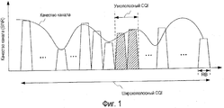
Что касается CQI, параметрами, показывающими качество канала смежных RB, соответствующих минимальной единице частотной диспетчеризации, являются "узкополосный CQI", т.е. CQI подполосы частот, а параметрами, показывающими качество канала полной полосы пропускания системы, является "широкополосный CQI", т.е. CQI полосы пропускания системы (см. непатентный документ 1). Узкополосный CQI считывается как качество канала, получаемое при обработке приема в мобильной станции, когда базовая станция выделяет заранее определенные подполосы частот, и используется для адаптивной модуляции подполос частот. Между тем, широкополосный CQI считывается как усредненное качество канала, получаемое при обработке приема в мобильной станции, когда базовая станция выделяет произвольные подполосы частот, и используется для адаптивной модуляции произвольных подполос частот.As for the CQI, the parameters showing the channel quality of adjacent RBs corresponding to the minimum frequency scheduling unit are “narrowband CQI”, i.e. CQI sub-bands, and the parameters showing the quality of the channel of the full bandwidth of the system is "wideband CQI", i.e. CQI system bandwidth (see Non-Patent Document 1). The narrowband CQI is read as the channel quality obtained by receiving processing in the mobile station when the base station allocates predetermined frequency subbands and is used for adaptively modulating the subbands. Meanwhile, the wideband CQI is read as the average channel quality obtained by receiving processing in the mobile station when the base station allocates arbitrary frequency subbands, and is used to adaptively modulate arbitrary subbands.
Фиг.1 иллюстрирует узкополосный CQI и широкополосный CQI. Как показано на фиг.1, полная полоса пропускания системы формируется с помощью множества RB. Дополнительно, на фиг.1, мобильная станция измеряет узкополосный (подполосы частот) CQI посредством оценки, например, SINR (отношение "сигнал-к-помехам-и-шуму"), качества канала двух смежных RB и измеряет широкополосный CQI посредством оценки качества канала полной полосы пропускания системы.1 illustrates narrowband CQI and broadband CQI. As shown in FIG. 1, a full system bandwidth is generated using a plurality of RBs. Additionally, in FIG. 1, a mobile station measures narrowband (sub-band) CQIs by evaluating, for example, SINR (signal-to-interference-and-noise), channel quality of two adjacent RBs and measures wideband CQI by estimating channel quality full system bandwidth.
Непатентный документ 1. 3GPP Rl-073681, Nokia Siemens Networks, Nokia, "CQI reporting requirements for E-UTRA UE", 20-24 августа 2007 года.Non-Patent
Сущность изобретенияSUMMARY OF THE INVENTION
Проблемы, разрешаемые изобретениемProblems Resolved by the Invention
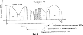
Тем не менее, в системе связи, предоставляющей множество полос пропускания в качестве полос пропускания системы, к примеру, LTE (стандарт долгосрочного развития), мобильная станция должна оценивать качество канала полной полосы пропускания системы посредством соответствия множеству полос пропускания системы, чтобы измерять множество широкополосных CQI. Дополнительно, чтобы оценивать качество канала, мобильная станция требует такой пропускной способности при декодировании, чтобы поддерживать все несколько скоростей передачи, когда множество полос пропускания системы используется. Например, мобильная станция требует пропускной способности при декодировании в 30 Мбит/с, чтобы поддерживать скорость передачи при использовании полосы пропускания системы на 10 МГц. Следовательно, объем обработки, требуемый для мобильной станции, увеличивается.However, in a communication system that provides multiple bandwidths as the system bandwidths, for example, LTE (Long Term Evolution Standard), the mobile station must evaluate the channel quality of the system’s full bandwidth by matching multiple system bandwidths in order to measure multiple wideband CQIs . Additionally, in order to evaluate channel quality, a mobile station requires such bandwidth during decoding to support all multiple transmission rates when multiple system bandwidths are used. For example, a mobile station requires 30 Mbps decoding throughput in order to maintain the transmission rate when using a system bandwidth of 10 MHz. Therefore, the amount of processing required for the mobile station is increasing.
Фиг.2 поясняет эти проблемы. Фиг.2 показывает в качестве примера случай, где система связи предоставляет три полосы пропускания системы, 10 МГц, 5 МГц и 3 МГц. Здесь, CQI представляется, например, посредством TBS (размер транспортного блока). TBS представляет число информационных битов, которые могут быть переданы при одновременном удовлетворении заранее определенной частоте ошибок по пакетам во всей полосе пропускания системы, когда связь выполняется с SINR канала, измеряемым в мобильной станции. Мобильная станция должна хранить таблицы CQI, в которых TBS ассоциированы с индексами CQI, соответствующими множеству полос пропускания системы (10 МГц, 5 МГц и 3 МГц), соответственно. Мобильная станция находит значение TBS посредством оценки канала, формирует индекс CQI со ссылкой на таблицу CQI, ассоциированную с полосой пропускания системы, и возвращает индекс CQI в базовую станцию. Например, когда полоса частот системы составляет 10 МГц (50 RB), мобильная станция выполняет оценку канала для полосы пропускания системы 10 МГц, чтобы получать TBS в 12000 битов как качество канала, и сообщает индекс CQI, ассоциированный с TBS в 12000 битов, в базовую станцию. Дополнительно, когда полоса частот системы составляет 5 МГц (25 RB), мобильная станция выполняет оценку канала для полосы пропускания системы 5 МГц, чтобы получать TBS в 6000 битов как качество канала, и сообщает индекс CQI, ассоциированный с TBS в 6000 битов, в базовую станцию.Figure 2 explains these problems. Figure 2 shows as an example the case where the communication system provides three system bandwidths, 10 MHz, 5 MHz and 3 MHz. Here, the CQI is represented, for example, by TBS (transport block size). TBS represents the number of information bits that can be transmitted while satisfying a predetermined packet error rate over the entire system bandwidth when communication is performed with a SINR channel measured at the mobile station. The mobile station must store CQI tables in which TBSs are associated with CQIs corresponding to a plurality of system bandwidths (10 MHz, 5 MHz and 3 MHz), respectively. The mobile station finds the TBS value by channel estimation, generates a CQI index with reference to the CQI table associated with the system bandwidth, and returns the CQI index to the base station. For example, when the system bandwidth is 10 MHz (50 RB), the mobile station performs a channel estimate for the system bandwidth of 10 MHz to obtain 12000 bits TBS as channel quality, and reports the CQI associated with 12000 bits TBS to the base station. Additionally, when the system bandwidth is 5 MHz (25 RB), the mobile station performs a channel estimate for the 5 MHz system bandwidth to obtain 6000-bit TBS as channel quality, and reports the CQI associated with the 6000-bit TBS to the base station.
Следовательно, задача настоящего изобретения заключается в том, чтобы предоставить приемное устройство и способ связи, которые позволяют уменьшать объем обработки для измерения и сообщения CQI в системе связи, предоставляющей множество полос пропускания системы.Therefore, it is an object of the present invention to provide a receiving device and a communication method that can reduce the processing amount for measuring and reporting CQI in a communication system providing a plurality of system bandwidths.
Средство решения проблемыProblem Solver
Приемное устройство настоящего изобретения применяет конфигурацию, включающую в себя: модуль измерения первого CQI, который измеряет CQI для блоков ресурсов, чтобы уровнять число блоков ресурсов для измерения CQI, из начальной позиции подполосы частот, передаваемой из передающего устройства, как первый CQI; модуль измерения второго CQI, который извлекает блоки ресурсов, чтобы уровнять число блоков ресурсов для измерения CQI, из полосы пропускания системы, передаваемой из передающего устройства, и измеряет средний CQI для извлеченных блоков ресурсов как второй CQI для полной полосы пропускания системы; и модуль обратной связи, который возвращает первый CQI и второй CQI в передающее устройство.The receiver of the present invention employs a configuration including: a first CQI measurement module that measures CQI for resource blocks to level the number of resource blocks for CQI measurement from an initial position of a frequency band transmitted from the transmitter as a first CQI; a second CQI measurement module that extracts resource blocks to level the number of resource blocks for CQI measurement from the system bandwidth transmitted from the transmitter and measures the average CQI for the extracted resource blocks as a second CQI for the total system bandwidth; and a feedback module that returns the first CQI and second CQI to the transmitter.
Способ настоящего изобретения содержит этапы: измерения CQI для блоков ресурсов, чтобы уровнять число блоков ресурсов для измерения CQI, из начальной позиции подполосы частот, передаваемой из передающего устройства, как первого CQI; извлечения блоков ресурсов, чтобы уровнять число блоков ресурсов для измерения CQI, из полосы пропускания системы, передаваемой из передающего устройства, и измерения среднего CQI для извлеченных блоков ресурсов как второго CQI для полной полосы пропускания системы; и возврат первого CQI и второго CQI в передающее устройство.The method of the present invention comprises the steps of: measuring CQI for resource blocks to level the number of resource blocks for measuring CQI, from the starting position of the frequency subband transmitted from the transmitter as the first CQI; extracting resource blocks to level the number of resource blocks for measuring the CQI from the system bandwidth transmitted from the transmitter and measuring the average CQI for the extracted resource blocks as a second CQI for the total system bandwidth; and returning the first CQI and second CQI to the transmitter.
Преимущества изобретенияAdvantages of the Invention
Согласно настоящему изобретению, можно уменьшать объем обработки в приемном устройстве для измерения и сообщения CQI в системе связи, предоставляющей множество полос пропускания системы.According to the present invention, it is possible to reduce the amount of processing at the receiver for measuring and reporting CQI in a communication system providing multiple system bandwidths.
Краткое описание чертежейBrief Description of the Drawings
Фиг.1 поясняет узкополосный CQI и широкополосный CQI в предшествующем уровне техники;Figure 1 illustrates the narrowband CQI and wideband CQI in the prior art;
Фиг.2 поясняет проблемы в предшествующем уровне техники;Figure 2 explains the problems in the prior art;
Фиг.3 является блок-схемой, показывающей конфигурацию приемного устройства согласно варианту 1 осуществления настоящего изобретения;FIG. 3 is a block diagram showing a configuration of a receiving device according to
Фиг.4 поясняет подробности обработки измерения CQI в модуле измерения узкополосного CQI и модуле измерения широкополосного CQI согласно варианту 1 осуществления настоящего изобретения;Figure 4 explains the details of the CQI measurement processing in the narrowband CQI measurement module and the wideband CQI measurement module according to
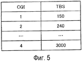
Фиг.5 показывает пример таблицы CQI согласно варианту 1 осуществления настоящего изобретения;5 shows an example of a CQI table according to
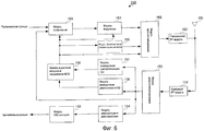
Фиг.6 является блок-схемой, показывающей конфигурацию передающего устройства согласно варианту 1 осуществления настоящего изобретения;6 is a block diagram showing a configuration of a transmission device according to
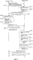
Фиг.7 является схемой последовательности операций, показывающей операции приемного устройства и передающего устройства согласно варианту 1 осуществления настоящего изобретения;7 is a flowchart showing operations of a receiving device and a transmitting device according to
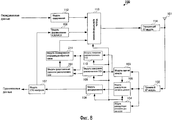
Фиг.8 является блок-схемой, показывающей конфигурацию приемного устройства согласно варианту 2 осуществления настоящего изобретения;8 is a block diagram showing a configuration of a receiving device according to
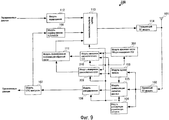
Фиг.9 является блок-схемой, показывающей конфигурацию приемного устройства согласно варианту 3 осуществления настоящего изобретения;9 is a block diagram showing a configuration of a receiving device according to Embodiment 3 of the present invention;
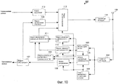
Фиг.10 является блок-схемой, показывающей конфигурацию приемного устройства согласно варианту 4 осуществления настоящего изобретения; и10 is a block diagram showing a configuration of a receiving device according to
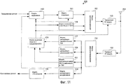
Фиг.11 является блок-схемой, показывающей конфигурацию передающего устройства согласно варианту 4 осуществления настоящего изобретения.11 is a block diagram showing a configuration of a transmission device according to
Оптимальный режим осуществления изобретенияThe optimal mode of carrying out the invention
Далее подробно описываются варианты осуществления настоящего изобретения со ссылкой на прилагаемые чертежи. Дополнительно, в вариантах осуществления компонентам, имеющим идентичные функции, назначаются идентичные ссылки с номером, и дублирующие описания опускаются.Embodiments of the present invention are described in detail below with reference to the accompanying drawings. Additionally, in embodiments, components having identical functions are assigned identical reference numbers, and duplicate descriptions are omitted.
(Первый вариант осуществления)(First Embodiment)
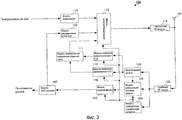
Фиг.3 это блок-схема, иллюстрирующая конфигурацию приемного устройства 100 согласно варианту 1 осуществления настоящего изобретения. Устройство мобильной станции является конкретным примером приемного устройства 100, показанного на фиг.3, и приемное устройство 100 поддерживает множество полос пропускания системы.3 is a block diagram illustrating a configuration of a
На фиг.3, приемный RF-модуль 102 принимает сигнал, передаваемый из передающего устройства 150 (описанного ниже), через антенну 101, выполняет обработку при радиоприеме, включающую в себя преобразование с понижением частоты и аналогово-цифровое преобразование для принимаемого сигнала, и, в сигнале после обработки при радиоприеме, выводит пилотный сигнал в модуль 103 оценки канала, выводит управляющий сигнал в модуль 104 демодуляции управляющих сигналов и выводит сигнал данных в модуль 105 демодуляции сигналов данных.3, the
Модуль 103 оценки канала вычисляет значение оценки канала (канальную матрицу) с использованием пилотного сигнала, выводимого из приемного RF-модуля 102, и выводит вычисленное значение оценки канала в модуль 105 демодуляции сигналов данных, модуль 109 измерения узкополосного CQI и модуль 110 измерения широкополосного CQI.The
Модуль 104 демодуляции управляющих сигналов демодулирует управляющий сигнал, выводимый из приемного RF-модуля 102, выводит полосу пропускания системы, включенную в демодулированный управляющий сигнал, в модуль 110 измерения широкополосного CQI, выводит начальную позицию для узкой полосы пропускания в модуль 109 измерения узкополосного CQI, выводит схему модуляции и скорость кодирования в модуль 105 демодуляции сигналов данных и модуль 106 декодирования, соответственно, и выводит результат выделения ресурсов в модуль 113 мультиплексирования. Здесь, если полоса пропускания системы составляет 10 МГц, полоса пропускания системы показывается в числе RB, соответствующих 10 МГц, а начальная позиция для узкой полосы пропускания показывается в номере RB.The control
Модуль 105 демодуляции сигналов данных демодулирует принимаемый сигнал, выводимый из приемного RF-модуля 102, с помощью значения оценки канала, выводимого из модуля 103 оценки канала, и схемы модуляции, выводимой из модуля 104 демодуляции управляющих сигналов, и выводит результат демодуляции в модуль 106 декодирования.The data
Модуль 106 декодирования декодирует результат демодуляции, выводимый из модуля 105 демодуляции сигналов данных, с помощью скорости кодирования, выводимой из модуля 104 демодуляции управляющих сигналов, и выводит сигнал декодированных данных (декодированные данные) в модуль 107 CRC-контроля.The
Модуль 107 CRC-контроля выполняет CRC-контроль для декодированных данных, выводимых из модуля 106 декодирования, чтобы обнаруживать, есть ошибка или нет. Модуль 107 CRC-контроля выводит результат обнаружения ошибок декодированных данных в модуль 108 формирования ACK/NACK и выводит декодированные данные без ошибки как принимаемые данные.The
Модуль 108 формирования ACK/NACK формирует АСК или NACK согласно результату обнаружения ошибок декодированных данных, выводимых из модуля 107 CRC-контроля. Таким образом, модуль 108 формирования ACK/NACK формирует АСК, если нет ошибки, и формирует NACK, если есть ошибка, и выводит сформированный ACK/NACK в модуль 113 мультиплексирования.The ACK /
На основе канальной матрицы, выводимой из модуля 103 оценки канала, модуль 109 измерения узкополосного CQI измеряет TBS в заранее определенном числе RB для измерения CQI, т.е. измеряет TBS узкой полосы пропускания из начальной позиции для узкой полосы пропускания, выводимой из модуля 104 демодуляции управляющих сигналов. Дополнительно, модуль 109 измерения узкополосного CQI, который хранит таблицу CQI, в которой TBS ассоциированы с индексами CQI, находит индекс CQI, ассоциированный с измеренным TBS узкой полосы пропускания, т.е. находит индекс узкополосного CQI в таблице CQI, и выводит индекс узкополосного CQI в модуль 111 формирования информации обратной связи. Обработка измерения CQI в модуле 109 измерения узкополосного CQI подробнее поясняется ниже.Based on the channel matrix output from the
Модуль 110 измерения широкополосного CQI извлекает заранее определенное число RB для измерения CQI из полосы пропускания системы, выводимой из модуля 104 демодуляции управляющих сигналов, и измеряет TBS для извлеченных RB на основе канальной матрицы, выводимой из модуля 103 оценки канала. Дополнительно, модуль 110 измерения широкополосного CQI, который хранит таблицу CQI, идентичную таблице CQI, хранимой в модуле 109 измерения узкополосного CQI, находит индекс CQI, ассоциированный с измеренным TBS в измеренной полосе пропускания системы, т.е. находит индекс широкополосного CQI в таблице CQI, и выводит индекс широкополосного CQI в модуль 111 формирования информации обратной связи. Обработка измерения CQI в модуле 110 измерения широкополосного CQI подробнее поясняется ниже.Broadband
Модуль 111 формирования информации обратной связи формирует информацию обратной связи, включающую в себя индекс узкополосного CQI, выводимый из модуля 109 измерения узкополосного CQI, и индекс широкополосного CQI, выводимый из модуля 110 измерения широкополосного CQI, и выводит сформированную информацию обратной связи в модуль 113 мультиплексирования. Модуль 108 формирования ACK/NACK и модуль 111 формирования информации обратной связи выступают в качестве модуля формирования управляющих каналов.The feedback
Модуль 112 кодирования кодирует передаваемые данные и выводит кодированные передаваемые данные в модуль 113 мультиплексирования.
Модуль 113 мультиплексирования формирует канал управления с помощью АСК или NACK, выводимых из модуля 108 формирования ACK/NACK, и информации обратной связи, выводимой из модуля 111 формирования информации обратной связи. Дополнительно, модуль 113 мультиплексирования мультиплексирует сформированный канал управления и передаваемые данные, выводимые из модуля 112 кодирования, на основе результата выделения ресурсов, выводимого из модуля 104 демодуляции управляющих сигналов, и выводит мультиплексированный сигнал в передающий RF-модуль 114.The
Передающий RF-модуль 114 выполняет обработку радиопередачи, включающую в себя цифроаналоговое преобразование и преобразование с повышением частоты для сигнала, выводимого из модуля 113 мультиплексирования, и выводит сигнал после обработки радиопередачи в передающее устройство 150 из антенны 101.The transmitting
Далее подробно поясняется обработка измерения CQI в модуле 109 измерения узкополосного CQI и модуле 110 измерения широкополосного CQI.The CQI measurement processing in the narrowband
Фиг.4 поясняет подробности обработки измерения CQI в модуле 109 измерения узкополосного CQI и модуле 110 измерения широкополосного CQI. На фиг.4, в качестве примера поясняется случай, где начальной позицией для узкой полосы пропускания, выводимой из модуля 104 демодуляции управляющих сигналов в модуль 109 измерения узкополосного CQI, является тридцатый RB, и где полоса пропускания системы, выводимая из модуля 104 демодуляции управляющих сигналов в модуль 110 измерения широкополосного CQI, составляет 10 МГц. На фиг.4, RB, показанные в диагональных линиях, являются RB, чтобы уровнять число RB для измерения CQI, извлеченному из полосы частот системы 10 МГц.4 explains the details of the CQI measurement processing in the narrowband
Как показано на фиг.4, число RB, в которых TBS измеряется в модуле 109 измерения узкополосного CQI, и число RB, в которых TBS измеряется в модуле 110 измерения широкополосного CQI, являются числом RB для измерения CQI, например, "5".As shown in FIG. 4, the number of RBs in which TBS is measured in narrowband
Модуль 110 измерения широкополосного CQI извлекает RB, чтобы уровнять число RB для измерения CQI, из полосы пропускания системы, выводимой из модуля 104 демодуляции управляющих сигналов. Например, когда полоса пропускания системы, выводимая из модуля 104 демодуляции управляющих сигналов, составляет 10 МГц, имеющая 50 RB, модуль 110 измерения широкополосного CQI извлекает первый, одиннадцатый, двадцать первый, тридцать первый и сорок первый RB из этих пятидесяти RB. Затем, модуль 110 измерения широкополосного CQI находит SINR в расчете на извлеченный RB с использованием значения оценки канала каждой поднесущей, выводимого из модуля 103 оценки канала. Затем, модуль 110 измерения широкополосного CQI находит среднее SINR из первого, одиннадцатого, двадцать первого, тридцать первого и сорок первого RB и на основе этого среднего значения, вычисляет возможный TBS при использовании ресурсов, равняющихся пяти RB. Затем, модуль 110 измерения широкополосного CQI обращается к предоставляемой таблице CQI, как показано на фиг.5, находит индекс широкополосного CQI, ассоциированный с вычисленным TBS, и выводит индекс широкополосного CQI в модуль 111 формирования информации обратной связи. Например, когда вычисленный TBS составляет 240 битов, модуль 110 измерения широкополосного CQI выводит "2" в качестве индекса широкополосного CQI в модуль 111 формирования информации обратной связи.Broadband
Между тем, модуль 109 измерения узкополосного CQI находит TBS в RB, чтобы уровнять число RB для измерения CQI, из начальной позиции для узкой полосы пропускания, выводимой из модуля 104 демодуляции управляющих сигналов. Например, модуль 109 измерения узкополосного CQI находит TBS в этих пяти RB, с тридцатого по тридцать четвертый RB, показанные на фиг.4. Далее, модуль 109 измерения узкополосного CQI находит индекс узкополосного CQI, ассоциированный с вычисленным TBS, со ссылкой на предоставляемую таблицу CQI, как показано на фиг.5, и выводит индекс узкополосного CQI в модуль 111 формирования информации обратной связи.Meanwhile, narrowband
Далее, в модуле 110 измерения широкополосного CQI, поясняется причина, по которой качество канала в полной полосе пропускания системы может показываться с использованием TBS для числа извлеченных RB для измерения CQI. Используя турбокоды, когда полоса пропускания системы превышает заранее определенное значение, например, 5 RB, информационные биты, которые могут быть переданы при одновременном удовлетворении заранее определенной частоте ошибок по пакетам, т.е. TBS, не зависят от SINR. Дополнительно, с точки зрения частотного разнесения, когда полоса пропускания превышает приблизительно 1 МГц (5 RB), информационные биты, которые могут быть переданы при одновременном удовлетворении заранее определенной частоте ошибок по пакетам, т.е. TBS, не зависят от SINR.Next, in the broadband
Следовательно, число RB, равное или превышающее нижний предел полосы пропускания системы, в которой TBS не зависит от SINR, заранее определяется как число RB для измерения CQI, посредством извлечения RB, чтобы уровнять число RB для измерения CQI, и измерения TBS модуль 110 измерения широкополосного CQI может получать индекс широкополосного CQI, показывающий качество канала полной полосы пропускания системы. Хотя на фиг.4 в качестве примера поясняется случай, где полоса пропускания системы, выводимая из модуля 104 демодуляции управляющих сигналов, составляет 10 МГц, если полоса пропускания системы, выводимая из модуля 104 демодуляции управляющих сигналов, не составляет 10 МГц и равна или превышает полосу пропускания, чтобы уровнять число RB для измерения CQI, например, 5 МГц или 3 МГц, модуль 110 измерения широкополосного CQI выполняет аналогичную обработку и может получать индекс широкополосного CQI. Таким образом, независимо от полосы пропускания системы модуль 110 измерения широкополосного CQI извлекает RB для измерения CQI и находит индекс широкополосного CQI с использованием таблицы CQI, показанной на фиг.5.Therefore, an RB number equal to or greater than the lower limit of the system bandwidth in which the TBS is independent of SINR is predetermined as an RB number for CQI measurement, by extracting an RB to level the RB number for CQI measurement, and a TBS measurement
Фиг.6 это блок-схема, иллюстрирующая конфигурацию передающего устройства 150 согласно варианту 1 осуществления настоящего изобретения. Устройство базовой станции является конкретным примером передающего устройства 150, показанного на фиг.6, и передающее устройство 150 поддерживает множество полос пропускания системы.6 is a block diagram illustrating a configuration of a
На фиг.6, приемный RF-модуль 152 принимает сигнал, передаваемый из приемного устройства 100, через антенну 151, выполняет обработку радиоприема, включающую в себя преобразование с понижением частоты и аналогово-цифровое преобразование для принимаемого сигнала, и выводит сигнал после обработки радиоприема в модуль 153 демультиплексирования.6, the receiving
Модуль 153 демультиплексирования демультиплексирует сигнал, выводимый из приемного RF-модуля 152, в индекс широкополосного CQI, индекс узкополосного CQI и АСК или NACK и сигнал данных. Модуль 153 демультиплексирования выводит демультиплексированный сигнал данных в модуль 154 демодуляции и декодирования, выводит индекс узкополосного CQI в модуль 156 демодуляции узкополосного CQI, выводит индекс широкополосного CQI в модуль 157 демодуляции широкополосного CQI и выводит АСК или NACK в модуль 160 кодирования.The
Модуль 154 демодуляции и декодирования демодулирует и декодирует сигнал данных, выводимый из модуля 153 демультиплексирования, и выводит декодированные данные в модуль 155 CRC-контроля.The demodulation and
Модуль 155 CRC-контроля выполняет CRC-контроль для декодированных данных, выводимых из модуля 154 демодуляции и декодирования, чтобы обнаруживать то, есть ли ошибка, и выводит декодированные данные без ошибки как принимаемые данные.The
Модуль 156 демодуляции узкополосного CQI демодулирует индекс узкополосного CQI, выводимый из модуля 153 демультиплексирования. Таким образом, модуль 156 демодуляции узкополосного CQI находит TBS, ассоциированный с индексом узкополосного CQI, со ссылкой на таблицу CQI и считывает TBS как информационные биты, которые могут быть переданы с RB, чтобы уровнять число RB для измерения CQI. Модуль 156 демодуляции узкополосного CQI выводит этот TBS как информацию, используемую при выделении ресурсов в узкой полосе пропускания, в модуль 158 выделения ресурсов и определения MCS (схемы модуляции и кодирования).The narrowband
Модуль 157 демодуляции широкополосного CQI демодулирует индекс широкополосного CQI, выводимый из модуля 153 демультиплексирования. Таким образом, модуль 157 демодуляции широкополосного CQI находит TBS, ассоциированный с индексом широкополосного CQI, со ссылкой на таблицу CQI и считывает TBS как информационные биты, которые могут быть переданы с RB, чтобы уровнять число RB для измерения CQI. Модуль 157 демодуляции широкополосного CQI выводит этот TBS как информацию, используемую при выделении ресурсов в полной полосе пропускания системы, в модуль 158 выделения ресурсов и определения MCS.The broadband
На основе TBS, выводимых из модуля 156 демодуляции узкополосного CQI и модуля 157 демодуляции широкополосного CQI, модуль 158 выделения ресурсов и определения MCS выделяет ресурсы, сформированные с помощью RB, чтобы уровнять число RB для измерения CQI, вплоть до числа RB полной полосы пропускания системы и выводит результат выделения ресурсов в модуль 159 формирования управляющих сигналов и модуль 162 мультиплексирования. Дополнительно, на основе TBS, выводимых из модуля 156 демодуляции узкополосного CQI и модуля 157 демодуляции широкополосного CQI, модуль 158 выделения ресурсов и определения MCS определяет скорость кодирования и схему модуляции и выводит определенную скорость кодирования и определенную схему модуляции в модуль 160 кодирования и модуль 161 модуляции, соответственно.Based on the TBSs output from the narrowband
Модуль 159 формирования управляющих сигналов формирует управляющий сигнал с использованием полосы пропускания системы, начальной позиции для узкой полосы пропускания, результата выделения ресурсов, скорости кодирования и схемы модуляции, выводимой из модуля 158 выделения ресурсов и определения MCS, и выводит сформированный управляющий сигнал в модуль 162 мультиплексирования.The control
Модуль 160 кодирования кодирует передаваемые данные с использованием скорости кодирования, выводимой из модуля 158 выделения ресурсов и определения MCS, и выводит, в модуль 161 модуляции, новые передаваемые данные или данные для повторной передачи в зависимости от АСК или NACK, выводимого из модуля 153 демультиплексирования. Таким образом, когда получено АСК, модуль 160 кодирования выводит новые передаваемые данные в модуль 161 модуляции, а когда получено NACK, модуль 160 кодирования выводит данные для повторной передачи в модуль 161 модуляции.
Модуль 161 модуляции модулирует передаваемые данные, выводимые из модуля 160 кодирования, с помощью схемы модуляции, выводимой из модуля 158 выделения ресурсов и определения MCS, и выводит модулированные передаваемые данные в модуль 162 мультиплексирования.
Модуль 162 мультиплексирования мультиплексирует передаваемые данные, выводимые из модуля 161 модуляции, и управляющий сигнал, выводимый из модуля 159 формирования управляющих сигналов, на основе результата выделения ресурсов, выводимого из модуля 158 выделения ресурсов и определения MCS, и выводит мультиплексированный сигнал в передающий RF-модуль 163.The
Передающий RF-модуль 163 выполняет обработку радиопередачи, включающую в себя цифроаналоговое преобразование и преобразование с повышением частоты для сигнала, выводимого из модуля 162 мультиплексирования, и передает сигнал после обработки радиопередачи в приемное устройство 100 из антенны 151.The transmitting
Далее поясняются операции вышеупомянутого приемного устройства 100 и передающего устройства 150 с использованием схемы последовательности операций, показанной на фиг.7.Next, operations of the
На фиг.7, на этапе (в дальнейшем в этом документе, просто "ST") 201, передающее устройство 150 передает пилотный канал в приемное устройство 100 и сообщает начальную позицию для узкой полосы пропускания и широкую полосу пропускания.7, in step (hereinafter, simply “ST”) 201, the transmitting
На этапе ST 202, модуль 109 измерения узкополосного CQI в приемном устройстве 100 измеряет узкополосный CQI, чтобы получать индекс узкополосного CQI.In step ST 202, the narrowband
На этапе ST 203, модуль 110 измерения широкополосного CQI в приемном устройстве 100 измеряет широкополосный CQI, чтобы получать индекс широкополосного CQI.In step ST 203, the broadband
На этапе ST 204, приемное устройство 100 сообщает индекс узкополосного CQI и индекс широкополосного CQI в передающее устройство 150.In step ST 204, the receiving
На этапе ST 205, модуль 156 демодуляции узкополосного CQI в передающем устройстве 150 демодулирует индекс узкополосного CQI, сообщаемый из приемного устройства 100, чтобы получать TBS, ассоциированный с индексом узкополосного CQI.In step ST 205, the narrowband
На этапе ST 206, модуль 157 демодуляции широкополосного CQI в передающем устройстве 150 демодулирует индекс широкополосного CQI, сообщаемый из приемного устройства 100, чтобы получать TBS, ассоциированный с индексом широкополосного CQI.In step ST 206, the broadband
На этапе ST 207 на основе TBS, модуль 158 выделения ресурсов и определения MCS в передающем устройстве 150 выделяет ресурсы и определяет скорость кодирования и схему модуляции.In a TBS based ST 207, the resource allocation and
На этапе ST 208, передающее устройство 150 передает пилотный канал в приемное устройство 100, сообщает начальную позицию для узкой полосы пропускания, полосу пропускания системы, результат выделения ресурсов и скорость кодирования и схему модуляции в управляющем сигнале и передает сигнал данных.At step ST 208, the
На этапе ST 209, модуль 104 демодуляции управляющих сигналов в приемном устройстве 100 демодулирует управляющий сигнал и получает начальную позицию для узкой полосы пропускания, полосу пропускания системы, результат выделения ресурсов и скорость кодирования и схему модуляции.In step ST 209, the control
На этапе ST 210, модуль 105 демодуляции сигналов данных в приемном устройстве 100 демодулирует сигнал данных.In step ST 210, the data
На этапе ST 211, модуль 106 декодирования в приемном устройстве 100 декодирует сигнал данных.In
На этапе ST 212 на основе результата CRC-контроля в модуле 107 CRC-контроля в приемном устройстве 100, модуль 108 формирования ACK/NACK в приемном устройстве 100 формирует сигнал АСК или сигнал NACK.In step ST 212, based on the result of the CRC control in the
На этапе ST 213, выполняется операция, идентичная операции на этапе ST 202. Таким образом, модуль 109 измерения узкополосного CQI в приемном устройстве 100 измеряет узкополосный CQI, чтобы получать индекс узкополосного CQI.In step ST 213, an operation identical to that in step ST 202 is performed. Thus, the narrowband
На этапе ST 214, выполняется операция, идентичная операции на этапе ST 203. Таким образом, модуль 110 измерения широкополосного CQI в приемном устройстве 100 измеряет широкополосный CQI, чтобы получать индекс широкополосного CQI.In step ST 214, an operation identical to that in step ST 203 is performed. Thus, the broadband
На этапе ST 215, приемное устройство 100 передает сигнал данных в передающее устройство 150 и сообщает индекс узкополосного CQI и индекс широкополосного CQI.In step ST 215, the
Таким образом, согласно варианту 1 осуществления, приемное устройство извлекает заранее определенное число RB от полной полосы пропускания системы независимо от полосы пропускания системы до тех пор, пока полоса пропускания системы равна или превышает заранее определенное значение, измеряет средний CQI из извлеченных RB и сообщает средний CQI в передающее устройство, так что можно уменьшать объем обработки для измерения CQI в приемном устройстве.Thus, according to
Хотя в настоящем варианте осуществления в качестве примера пояснен случай, где, во время обработки измерения CQI в модуле 110 измерения широкополосного CQI, число RB, которые используются для вычисления среднего SINR, и число RB при преобразовании числа ресурсов, предполагаемых, когда возможный TRB вычисляется, являются одинаковыми значениями, настоящее изобретение не ограничено этим, и полная полоса пропускания системы может использоваться для первого числа RB, и значение, идентичное числу RB для измерения CQI, может использоваться для второго числа RB.Although in the present embodiment, an example is explained where, during the CQI measurement processing in the broadband
Дополнительно, хотя в настоящем варианте осуществления в качестве примера пояснен случай, где как приемное устройство, так и передающее устройство хранят заранее определенное число RB для измерения CQI, настоящее изобретение не ограничено этим, и передающее устройство может хранить число RB для измерения CQI и может сообщать число RB для измерения CQI в приемное устройство.Further, although in the present embodiment, an example has been explained where both the receiver and the transmitter store a predetermined RB number for measuring CQI, the present invention is not limited to this, and the transmitter may store the RB number for CQI measurement and can report RB number for measuring CQI at the receiver.
Дополнительно, хотя в настоящем варианте осуществления в качестве примера пояснен случай, где передающее устройство сообщает начальную позицию для узкой полосы пропускания в приемное устройство с использованием управляющего сигнала, настоящее изобретение не ограничено этим, и передающее устройство и приемное устройство заранее совместно используют начальную позицию для узкой полосы пропускания. Дополнительно, число интервалов узкой полосы пропускания, в которых измеряется CQI, может превышать один, и в этом случае информация обратной связи может быть сформирована с использованием произвольного способа сжатия информации.Further, although in the present embodiment, a case is explained where the transmitting device communicates an initial position for a narrow passband to the receiving device using a control signal, the present invention is not limited thereto, and the transmitting device and the receiving device share the initial position for the narrow bandwidth. Additionally, the number of narrow bandwidth intervals in which CQI is measured may exceed one, in which case feedback information may be generated using an arbitrary information compression method.
Дополнительно, хотя в настоящем варианте осуществления пояснен случай, где индекс узкополосного CQI и индекс широкополосного CQI сообщаются одновременно из приемного устройства в передающее устройство, настоящее изобретение не ограничено этим, и индекс узкополосного CQI и индекс широкополосного CQI могут сообщаться в разное время. Например, индекс широкополосного CQI может сообщаться в более длительных циклах, чем индекс узкополосного CQI. (Второй вариант осуществления)Further, although in the present embodiment, a case is explained where the narrowband CQI index and the wideband CQI index are simultaneously communicated from the receiver to the transmission device, the present invention is not limited thereto, and the narrowband CQI index and the wideband CQI index can be reported at different times. For example, the broadband CQI index may be reported in longer cycles than the narrowband CQI index. (Second Embodiment)
Фиг.8 является блок-схемой, показывающей конфигурацию приемного устройства 200 согласно варианту 2 осуществления настоящего изобретения. Фиг.8 отличается от фиг.3 добавлением модуля 201 представления разности узкополосного CQI и изменением модуля 111 формирования информации обратной связи на модуль 211 формирования информации обратной связи.FIG. 8 is a block diagram showing a configuration of a
На фиг.8, модуль 201 представления разности узкополосного CQI представляет индекс узкополосного CQI, выводимый из модуля 109 измерения узкополосного CQI, как разность между индексом узкополосного CQI и индексом широкополосного CQI, выводимым из модуля 110 измерения широкополосного CQI, и выводит эту разность в модуль 211 формирования информации обратной связи.8, the narrowband CQI
Модуль 211 формирования информации обратной связи формирует информацию обратной связи, включающую в себя индекс широкополосного CQI, выводимый из модуля 110 измерения широкополосного CQI, и представление разности узкополосного CQI, выводимое из модуля 201 представления разности узкополосного CQI, и выводит сформированную информацию обратной связи в модуль 113 мультиплексирования.The feedback
Параллельно приемному устройству 200, передающее устройство (не показано) согласно настоящему варианту осуществления вычисляет индекс узкополосного CQI с использованием разности между индексом широкополосного CQI и индексом узкополосного CQI и индексом широкополосного CQI.In parallel to the
Таким образом, согласно варианту 2 осуществления, приемное устройство представляет индекс узкополосного CQI и индекс широкополосного CQI, показанные в одной таблице CQI, как разность и возвращает разность в передающее устройство, так что можно уменьшать объем информации обратной связи и повышать пропускную способность системы связи. (Третий вариант осуществления)Thus, according to
Фиг.9 показывает блок-схему, показывающую конфигурацию приемного устройства 300 согласно варианту 3 осуществления настоящего изобретения. Фиг.9 отличается от фиг.3 добавлением модуля 301 хранения числа RB для измерения CQI и изменением модуля 109 измерения узкополосного CQI и модуля 110 измерения широкополосного CQI на модуль 309 измерения узкополосного CQI и модуль 310 измерения широкополосного CQI.9 is a block diagram showing a configuration of a
На фиг.9, модуль 301 хранения числа RB для измерения CQI хранит таблицу, в которой полосы пропускания системы ассоциированы с числом RB для измерения CQI. Модуль 301 хранения числа RB для измерения CQI находит число RB для измерения CQI, ассоциированного с полосой пропускания системы, выводимой из модуля 104 демодуляции управляющих сигналов, со ссылкой на таблицу и выводит число RB для измерения CQI в модуль 309 измерения узкополосного CQI и модуль 310 измерения широкополосного CQI. В таблице, хранимой в модуле 301 хранения числа RB для измерения CQI, полосы пропускания системы являются кратными целыми от числа RB для измерения CQI. Дополнительно, в таблице, хранимой в модуле 301 хранения числа RB для измерения CQI, большая полоса пропускания системы ассоциирована с большим числом RB для измерения CQI. Например, число RB для измерения CQI, ассоциированного с полосой пропускания системы 5 МГц или менее, составляет 5 RB, а число RB для измерения CQI, ассоциированного с полосой пропускания системы 10 МГц или более, составляет 10 RB.In FIG. 9, an RB
Модуль 309 измерения узкополосного CQI и модуль 310 измерения широкополосного CQI отличаются от модуля 109 измерения узкополосного CQI и модуль 110 измерения широкополосного CQI на фиг.3 выполнением только обработки измерения CQI с помощью числа RB для измерения CQI, выводимого из модуля 301 хранения числа RB для измерения CQI, вместо заранее определенного числа RB для измерения CQI.The narrowband
Таким образом, согласно настоящему варианту осуществления, приемное устройство измеряет CQI с использованием числа RB для измерения CQI, ассоциированного с большей полосой пропускания системы, когда число RB для измерения CQI больше, так что можно уменьшать глубину обратной связи и повышать точность измерения CQI.Thus, according to the present embodiment, the receiver measures CQI using the RB number for measuring the CQI associated with a larger system bandwidth when the RB number for CQI measurement is greater, so that the feedback depth can be reduced and the accuracy of the CQI measurement can be improved.
В таблице, хранимой в модуле 301 хранения числа RB для измерения CQI, полосы пропускания системы могут группироваться на несколько групп, например, в зависимости от значений полос пропускания, и числа RB для измерения CQI могут быть по отдельности ассоциированы с группами.In the table stored in the RB
(Четвертый вариант осуществления)(Fourth Embodiment)
В варианте 4 осуществления настоящего изобретения приводится пояснение обработки измерения CQI, выполняемой в случае, если полоса пропускания системы меньше полосы пропускания, чтобы уровнять число RB для измерения CQI, например, когда полоса пропускания системы составляет 3 RB. Когда полоса пропускания системы меньше полосы пропускания, чтобы уровнять число RB для измерения CQI, информационные биты, которые могут быть переданы при одновременном удовлетворении заранее определенной частоте ошибок по пакетам, т.е. TBS, зависят от SINR.
Фиг.10 является блок-схемой, показывающей конфигурацию приемного устройства 400 согласно варианту 4 осуществления настоящего изобретения. Фиг.10 отличается от фиг.3 добавлением модуля 401 вычисления кривой SINR в зависимости от TBS и изменением модуля 111 формирования информации обратной связи на модуль 411 формирования информации обратной связи.10 is a block diagram showing a configuration of a
На фиг.10, когда полоса пропускания системы, выводимая из модуля 104 демодуляции управляющих сигналов, меньше полосы пропускания, чтобы уровнять число RB для измерения CQI, модуль 401 вычисления кривой SINR в зависимости от TBS вычисляет кривую SINR в зависимости от TBS на основе значения оценки канала, принимаемого в качестве ввода от модуля 103 оценки канала, и выводит вычисленную кривую SINR в зависимости от TBS в модуль 411 формирования информации обратной связи. Например, модуль 401 вычисления кривой SINR в зависимости от TBS вычисляет отношение между TBS в полосе пропускания, чтобы уровнять число RB для измерения CQI, и TBS в полосе пропускания системы или разность между TBS в полосе пропускания, чтобы уровнять число RB для измерения CQI, и TBS в полосе пропускания системы как кривую SINR в зависимости от TBS.10, when the system bandwidth output from the control
Модуль 411 формирования информации обратной связи формирует информацию обратной связи, включающую в себя кривую SINR в зависимости от TBS, выводимую из модуля 401 вычисления кривой SINR в зависимости от TBS, и индекс узкополосного CQI, выводимый из модуля 109 измерения узкополосного CQI, и выводит сформированную информацию обратной связи в модуль 113 мультиплексирования. Либо модуль 411 формирования информации обратной связи формирует информацию обратной связи, включающую в себя индекс узкополосного CQI, выводимый из модуля 109 измерения узкополосного CQI, и индекс широкополосного CQI, выводимый из модуля 110 измерения широкополосного CQI, и выводит сформированную информацию обратной связи в модуль 113 мультиплексирования.The feedback
Фиг.11 является блок-схемой, показывающей конфигурацию передающего устройства 450 согласно варианту 4 осуществления настоящего изобретения. Фиг.11 отличается от фиг.6 добавлением модуля 451 демодуляции кривой SINR в зависимости от TBS и изменением модуля 158 выделения ресурсов и определения MCS на модуль 458 выделения ресурсов и определения MCS.11 is a block diagram showing a configuration of a
Модуль 451 демодуляции кривой SINR в зависимости от TBS демодулирует кривую SINR в зависимости от TBS, выводимую из модуля 153 демультиплексирования, и выводит демодулированную кривую SINR в зависимости от TBS в модуль 458 выделения ресурсов и определения MCS.The TBS-dependent SINR
На основе кривой SINR в зависимости от TBS, выводимой из модуля 451 демодуляции кривой SINR в зависимости от TBS, модуль 458 выделения ресурсов и определения MCS оценивает увеличение требования SINR, когда число выделенных RB является небольшим и не удовлетворяет заданному TBS, и командует передающему RF-модулю 163 повышать мощность передачи по мере необходимости. Хотя, когда требование SINR увеличивается, в данном случае повышается мощность передачи, в равной степени можно уменьшать число битов, когда требование SINR увеличивается, тем самым увеличивая выигрыш от кодирования.Based on the TIN-dependent SINR curve outputted from the TBS-dependent SINR
Таким образом, согласно варианту 4 осуществления, можно повышать гибкость, чтобы сокращать число RB при выделении ресурсов и обеспечивать точность адаптации линии связи.Thus, according to
Выше описаны варианты осуществления настоящего изобретения.Embodiments of the present invention are described above.
Дополнительно, хотя в вышеприведенном варианте осуществления в качестве примеров описаны случаи, где настоящее изобретение выполнено посредством аппаратных средств, настоящее изобретение также может быть реализовано посредством программного обеспечения.Additionally, although in the above embodiment, examples are described where the present invention is implemented by means of hardware, the present invention can also be implemented by software.
Каждый функциональный блок, используемый в пояснении каждого из вышеприведенных вариантов осуществления, типично может быть реализован как LSI, состоящая из интегральной схемы. Это могут быть отдельные микросхемы либо они могут частично или полностью содержаться на одной микросхеме. В данном документе употребляется термин LSI, но она также может упоминаться как 1C, "системная LSI", "супер-LSI" или "ультра-LSI" в зависимости от отличающейся степени интеграции.Each functional block used in the explanation of each of the above embodiments may typically be implemented as an LSI consisting of an integrated circuit. It can be separate microcircuits or they can be partially or completely contained on one microcircuit. The term LSI is used throughout this document, but it may also be referred to as 1C, “system LSI”, “super-LSI” or “ultra-LSI” depending on the varying degree of integration.
Более того, способ интеграции микросхем не ограничен LSI, и реализация с помощью специализированных схем или процессора общего назначения также возможна. После изготовления LSI, использование программируемой FPGA (программируемой пользователем вентильной матрицы) или реконфигурируемого процессора, где соединения или разъемы ячеек схемы в рамках LSI могут быть переконфигурированы, также возможно.Moreover, the method of integrating microcircuits is not limited to LSI, and implementation using specialized circuits or a general-purpose processor is also possible. After manufacturing an LSI, the use of a programmable FPGA (Field Programmable Gate Array) or a reconfigurable processor where the connections or connectors of circuit cells within the LSI can be reconfigured is also possible.
Кроме того, если появится технология интегральных микросхем, чтобы заменять LSI, в результате усовершенствования полупроводниковой технологии или другой производной технологии, разумеется, также можно выполнять интеграцию функциональных блоков с помощью этой технологии. Применение биотехнологии также допускается.In addition, if integrated circuit technology appears to replace LSI, as a result of improvements in semiconductor technology or other derivative technology, it is of course also possible to integrate function blocks using this technology. The use of biotechnology is also allowed.
Раскрытие сущности патентной заявки (Япония) номер 2007-257779, поданной 1 октября 2007 года, включая подробное описание, чертежи и реферат, полностью содержится в данном документе по ссылке.Disclosure of the essence of the patent application (Japan) number 2007-257779, filed October 1, 2007, including a detailed description, drawings and abstract, is fully contained in this document by reference.
Промышленная применимостьIndustrial applicability
Приемное устройство и способ связи согласно настоящему изобретению применимы к системам связи, предоставляющим множество полос пропускания системы, например, к системам мобильной связи.The receiver and communication method according to the present invention are applicable to communication systems providing multiple system bandwidths, for example, to mobile communication systems.
Claims (24)
модуль измерения, сконфигурированный для получения, с использованием таблицы CQI, включающей в себя индекс CQI, представляющий собой качество канала и соответствующий размеру транспортного блока данных, индекса CQI подполосы частот для подполосы частот, которая представляет собой набор из множества смежных блоков ресурсов, каждый из которых содержит множество последовательных поднесущих в частотной области, и индекса широкополосного CQI для полной полосы пропускания системы; и
передающий модуль, сконфигурированный для передачи индекса CQI подполосы частот и индекса широкополосного CQI в передающее устройство;
причем упомянутый модуль измерения получает индекс CQI подполосы частот и индекс широкополосного CQI с использованием одной и той же таблицы CQI.1. A receiving device receiving data transmitted from a transmitting device in a communication system in which a plurality of system bandwidths is configured, said receiving device comprising:
a measurement module, configured to obtain, using a CQI table including a CQI index representing channel quality and corresponding to the size of a data transport block, a subband CQI index for a frequency subband, which is a set of a plurality of adjacent resource blocks, each of which contains many consecutive subcarriers in the frequency domain, and a broadband CQI index for the full system bandwidth; and
a transmitting module configured to transmit the CQI index of the subband frequency and the index of the broadband CQI in the transmitting device;
wherein said measurement module obtains a subband CQI index and a broadband CQI index using the same CQI table.
передающий модуль, сконфигурированный для передачи пилотного сигнала в приемное устройство; и
приемный модуль, сконфигурированный для приема сигнала, включающего в себя индекс CQI подполосы частот для подполосы частот, которая представляет собой набор из множества смежных блоков ресурсов, каждый из которых содержит множество последовательных поднесущих в частотной области, и индекс широкополосного CQI для полной полосы пропускания системы, причем индекс CQI подполосы частот и индекс широкополосного CQI получены на основе пилотного сигнала с использованием таблицы CQI, включающей в себя индекс CQI, который представляет собой качество канала и который соответствует размеру транспортного блока данных, в приемном устройстве;
причем индекс CQI подполосы частот и индекс широкополосного CQI получены с использованием одной и той же таблицы CQI.12. A transmitting device transmitting data to a receiving device in a communication system in which a plurality of system bandwidths are configured, said transmitting device comprising:
a transmitting module configured to transmit a pilot signal to a receiver; and
a receiving module configured to receive a signal including a subband CQI index for a frequency subband, which is a set of a plurality of adjacent resource blocks, each of which contains a plurality of consecutive subcarriers in the frequency domain, and a broadband CQI index for the overall system bandwidth, moreover, the subband CQI index and the wideband CQI index are obtained based on the pilot signal using the CQI table including the CQI index, which is the quality of Nala and which corresponds to the size of the transport data block at the receiving device;
moreover, the CQI index of the subband frequency and the index of wideband CQI obtained using the same CQI table.
получают с использованием таблицы CQI, включающей в себя индекс CQI, представляющий собой качество канала и соответствующий размеру транспортного блока данных, индекс CQI подполосы частот для подполосы частот, которая представляет собой набор из множества смежных блоков ресурсов, каждый из которых содержит множество последовательных поднесущих в частотной области, и индекс широкополосного CQI для полной полосы пропускания системы; и
сообщают индекс CQI подполосы частот и индекс широкополосного CQI;
причем индекс CQI подполосы частот и индекс широкополосного CQI получают с использованием одной и той же таблицы CQI.21. A method for transmitting data in a communication system in which a plurality of system bandwidths are configured, said method comprising the steps of:
obtained using a CQI table including a CQI index representing channel quality and corresponding to the size of a data transport block, a subband CQI index for a frequency subband, which is a set of a plurality of adjacent resource blocks, each of which contains a plurality of consecutive subcarriers in the frequency areas, and the Broadband CQI index for the full system bandwidth; and
reporting a subband CQI index and a broadband CQI index;
moreover, the subband CQI index and the broadband CQI index are obtained using the same CQI table.
передают пилотный сигнал в приемное устройство; и
принимают сигнал, включающий в себя индекс CQI подполосы частот для подполосы частот, которая представляет собой набор из множества смежных блоков ресурсов, каждый из которых содержит множество последовательных поднесущих в частотной области, и индекс широкополосного CQI для полной полосы пропускания системы, причем индекс CQI подполосы частот и индекс широкополосного CQI получают на основе пилотного сигнала с использованием таблицы CQI, включающей в себя индекс CQI, который представляет собой качество канала и который соответствует размеру транспортного блока данных, в приемном устройстве;
причем индекс CQI подполосы частот и индекс широкополосного CQI получают с использованием одной и той же таблицы CQI.22. A method for transmitting data in a communication system in which a plurality of system bandwidths are configured, said method comprising the steps of:
transmitting a pilot signal to a receiver; and
receiving a signal including a CQI index of the subband for the frequency subband, which is a set of many adjacent resource blocks, each of which contains many consecutive subcarriers in the frequency domain, and a broadband CQI index for the overall system bandwidth, the subband CQI index and the broadband CQI index is obtained based on the pilot signal using the CQI table including the CQI index, which is the channel quality and which corresponds to the size t ansportnogo data block at the receiving device;
moreover, the subband CQI index and the broadband CQI index are obtained using the same CQI table.
измеряют с использованием таблицы CQI, включающей в себя индекс CQI, представляющий собой качество канала и соответствующий размеру транспортного блока данных, индекс CQI подполосы частот для подполосы частот, которая представляет собой набор из множества смежных блоков ресурсов, каждый из которых содержит множество последовательных поднесущих в частотной области, и индекс широкополосного CQI для полной полосы пропускания системы; и
сообщают индекс CQI подполосы частот и индекс широкополосного CQI;
причем индекс CQI подполосы частот и индекс широкополосного CQI получены с использованием одной и той же таблицы CQI.23. An integrated circuit for controlling a process in a communication system in which a plurality of system bandwidths are configured, said process comprising the steps of:
measured using a CQI table including a CQI index representing channel quality and corresponding to the size of a data transport block, a subband CQI index for a frequency subband, which is a set of a plurality of adjacent resource blocks, each of which contains a plurality of consecutive subcarriers in the frequency areas, and the Broadband CQI index for the full system bandwidth; and
reporting a subband CQI index and a broadband CQI index;
moreover, the CQI index of the subband frequency and the index of wideband CQI obtained using the same CQI table.
передают пилотный сигнал в приемное устройство; и
принимают сигнал, включающий в себя индекс CQI подполосы частот для подполосы частот, которая представляет собой набор из множества смежных блоков ресурсов, каждый из которых содержит множество последовательных поднесущих в частотной области, и индекс широкополосного CQI для полной полосы пропускания системы, причем индекс CQI подполосы частот и индекс широкополосного CQI получены на основе пилотного сигнала с использованием таблицы CQI, включающей в себя индекс CQI, который представляет собой качество канала и который соответствует размеру транспортного блока данных, в приемном устройстве;
причем индекс CQI подполосы частот и индекс широкополосного CQI получены с использованием одной и той же таблицы CQI. 24. An integrated circuit for controlling a process in a communication system in which a plurality of system bandwidths are configured, said process comprising the steps of:
transmitting a pilot signal to a receiver; and
receiving a signal including a CQI index of the subband for the frequency subband, which is a set of many adjacent resource blocks, each of which contains many consecutive subcarriers in the frequency domain, and a broadband CQI index for the overall system bandwidth, the subband CQI index and the broadband CQI index are obtained based on the pilot signal using the CQI table including the CQI index, which is the channel quality and which corresponds to the size t ansportnogo data block at the receiving device;
moreover, the CQI index of the subband frequency and the index of wideband CQI obtained using the same CQI table.
Applications Claiming Priority (3)
| Application Number | Priority Date | Filing Date | Title |
|---|---|---|---|
| JP2007257779 | 2007-10-01 | ||
| JP2007-257779 | 2007-10-01 | ||
| PCT/JP2008/002737 WO2009044536A1 (en) | 2007-10-01 | 2008-09-30 | Receiver apparatus and communication method |
Publications (2)
| Publication Number | Publication Date |
|---|---|
| RU2010112602A RU2010112602A (en) | 2011-10-10 |
| RU2490820C2 true RU2490820C2 (en) | 2013-08-20 |
Family
ID=40525968
Family Applications (1)
| Application Number | Title | Priority Date | Filing Date |
|---|---|---|---|
| RU2010112602/07A RU2490820C2 (en) | 2007-10-01 | 2008-09-30 | Receiver apparatus and communication method |
Country Status (9)
| Country | Link |
|---|---|
| US (4) | US7970001B2 (en) |
| EP (2) | EP2205017B1 (en) |
| JP (5) | JP4615062B2 (en) |
| KR (1) | KR101473041B1 (en) |
| CN (3) | CN103957077B (en) |
| AU (1) | AU2008308378B2 (en) |
| BR (1) | BRPI0817596B1 (en) |
| RU (1) | RU2490820C2 (en) |
| WO (1) | WO2009044536A1 (en) |
Families Citing this family (31)
| Publication number | Priority date | Publication date | Assignee | Title |
|---|---|---|---|---|
| CN103957077B (en) * | 2007-10-01 | 2018-01-02 | 松下电器(美国)知识产权公司 | Reception device, dispensing device, data communications method and integrated circuit |
| JP5371768B2 (en) * | 2007-10-30 | 2013-12-18 | 株式会社エヌ・ティ・ティ・ドコモ | User device and signal power measurement method |
| JP4893618B2 (en) * | 2007-12-27 | 2012-03-07 | 富士通東芝モバイルコミュニケーションズ株式会社 | Mobile radio terminal apparatus and mobile communication system |
| EP2228933B1 (en) | 2008-01-04 | 2012-07-11 | Panasonic Corporation | Radio transmitting device and radio transmitting method |
| US8301177B2 (en) * | 2009-03-03 | 2012-10-30 | Intel Corporation | Efficient paging operation for femtocell deployment |
| JP2010263256A (en) * | 2009-04-28 | 2010-11-18 | Ntt Docomo Inc | Mobile station and mobile communication system |
| EP2439994A1 (en) * | 2009-06-02 | 2012-04-11 | Sharp Kabushiki Kaisha | Wireless communication system, wireless communication method, base station apparatus, and terminal station apparatus |
| JP5331593B2 (en) * | 2009-06-25 | 2013-10-30 | 京セラ株式会社 | Radio base station and resource allocation method |
| US8315183B2 (en) * | 2009-12-23 | 2012-11-20 | Intel Corporation | Channel quality indexing and reverse indexing |
| US8630311B2 (en) * | 2010-05-10 | 2014-01-14 | Futurewei Technologies, Inc. | System and method for reporting quantized feedback information for adaptive codebooks |
| JP5451675B2 (en) * | 2011-04-04 | 2014-03-26 | 株式会社Nttドコモ | Mobile device and method |
| WO2012154095A1 (en) * | 2011-05-10 | 2012-11-15 | Telefonaktiebolaget L M Ericsson (Publ) | Methods and arrangements for handling a scheduling of a narrowband transmission in a cellular network |
| ITTO20110906A1 (en) * | 2011-10-11 | 2013-04-12 | Csp A Innovazione Nelle Ict Scarl | METHOD AND SYSTEM TO GENERATE A MODULAR SIGNAL AS WELL AS METHOD AND SYSTEM TO PROCESS A MODULAR SIGNAL |
| CN104094634A (en) * | 2012-02-01 | 2014-10-08 | 富士通株式会社 | Wireless communication system, wireless terminal, wireless base station, and wireless communication method |
| WO2014029108A1 (en) | 2012-08-24 | 2014-02-27 | Panasonic Corporation | Communication method, base station and user equipment |
| US9294935B2 (en) | 2012-08-30 | 2016-03-22 | Qualcomm Incorporated | Apparatus and method for exploiting frequency diversity for neighboring cell measurements |
| EP2919512A4 (en) * | 2012-11-06 | 2016-06-15 | Kyocera Corp | Communication control method, base station, and processor |
| WO2014077658A1 (en) * | 2012-11-19 | 2014-05-22 | 엘지전자 주식회사 | Method of reporting measurement in wireless communication system and device for supporting said method |
| US9712306B2 (en) | 2013-01-21 | 2017-07-18 | Apple Inc. | Adaptive link adaptation for wireless communications |
| CN105075327A (en) * | 2013-03-15 | 2015-11-18 | 高通股份有限公司 | Predicting channel state |
| WO2014183286A1 (en) * | 2013-05-16 | 2014-11-20 | Telefonaktiebolaget L M Ericsson (Publ) | Method and apparatus for rank override |
| CN110351870B (en) * | 2013-12-31 | 2021-12-10 | 华为技术有限公司 | Method and apparatus for measuring channel state information |
| JP2015185932A (en) * | 2014-03-20 | 2015-10-22 | 株式会社Nttドコモ | User terminal, radio base station, and radio communication method |
| US9949263B2 (en) * | 2015-02-25 | 2018-04-17 | Qualcomm Incorporated | Frequency resource allocation for a narrow-band cellular internet of things system |
| CN107466452B (en) | 2015-04-08 | 2020-07-03 | Lg 电子株式会社 | Method and device for reporting channel state |
| EP3365986B1 (en) * | 2015-10-23 | 2020-06-03 | LG Electronics Inc. | Method and apparatus for defining wideband cqi in wireless communication system |
| JP2016189591A (en) * | 2016-05-02 | 2016-11-04 | 富士通株式会社 | Information feedback method, user device, and base station |
| WO2018126456A1 (en) * | 2017-01-06 | 2018-07-12 | 广东欧珀移动通信有限公司 | Measurement method, base station and terminal |
| US11469806B2 (en) | 2017-09-15 | 2022-10-11 | Apple Inc. | CSI measurement and feedback for eMTC-U system |
| CN110582075B (en) * | 2018-06-07 | 2022-11-29 | 中国电信股份有限公司 | Narrow-band Internet of things signal measuring method and system and application client |
| CN111050349B (en) * | 2018-10-12 | 2021-12-03 | 华为技术有限公司 | Method, device and system for determining channel quality information |
Citations (6)
| Publication number | Priority date | Publication date | Assignee | Title |
|---|---|---|---|---|
| RU2274955C2 (en) * | 2002-10-24 | 2006-04-20 | Нокиа Корпорейшн | Method for improving signaling about size of data transporting block |
| EP1662689A2 (en) * | 2004-11-25 | 2006-05-31 | Fujitsu Limited | Radio communication apparatus and mobile station using adaptive modulation |
| EP1750407A1 (en) * | 2005-08-01 | 2007-02-07 | Motorola, Inc. | Channel quality indicator for time, frequency and spatial channel in terrestrial radio access network |
| EP1750408A2 (en) * | 2005-08-01 | 2007-02-07 | Samsung Electronics Co., Ltd. | Apparatus and method for channel quality feedback in a multicarrier wireless network |
| JP2007129377A (en) * | 2005-11-02 | 2007-05-24 | Nec Corp | Mobile communication system and mobil station, and decode control method thereof |
| EP1821470A1 (en) * | 2006-02-15 | 2007-08-22 | Samsung Electronics Co., Ltd. | System and method for allocating a channel in a communication system |
Family Cites Families (19)
| Publication number | Priority date | Publication date | Assignee | Title |
|---|---|---|---|---|
| US7050759B2 (en) * | 2002-02-19 | 2006-05-23 | Qualcomm Incorporated | Channel quality feedback mechanism and method |
| KR20050119590A (en) * | 2004-06-16 | 2005-12-21 | 삼성전자주식회사 | Apparatus and method for feedback of channel quality information in a communication system using orthogonal frequency division multiplexing scheme |
| US7317702B2 (en) * | 2004-07-30 | 2008-01-08 | Lucent Technologies Inc. | Method and apparatus for enhancing performance of channel quality indicator (CQI) channel in wireless communications system |
| US7548752B2 (en) * | 2004-12-22 | 2009-06-16 | Qualcomm Incorporated | Feedback to support restrictive reuse |
| US7872981B2 (en) * | 2005-05-12 | 2011-01-18 | Qualcomm Incorporated | Rate selection for eigensteering in a MIMO communication system |
| KR101124932B1 (en) * | 2005-05-30 | 2012-03-28 | 삼성전자주식회사 | Apparatus and method for transmitting/receiving a data in mobile communication system with array antennas |
| KR101119281B1 (en) * | 2005-08-29 | 2012-03-15 | 삼성전자주식회사 | Apparatus and method of feedback channel quality information and scheduling apparatus and method using thereof in a wireless communication system |
| KR20070027844A (en) * | 2005-08-29 | 2007-03-12 | 삼성전자주식회사 | Method and apparatus for transmitting channel quality information in a wireless communication system |
| US8054894B2 (en) | 2005-10-31 | 2011-11-08 | Motorola Mobility, Inc. | Method and apparatus for providing channel quality feedback in an orthogonal frequency division multiplexing communication system |
| US20070177501A1 (en) * | 2006-01-31 | 2007-08-02 | Texas Instruments Incorporated | Signaling Requirements to Support Interference Coordination in OFDMA Based Systems |
| CN101039165B (en) * | 2006-03-14 | 2011-07-06 | 华为技术有限公司 | Information feedback method based on multi-antenna self-adaptive modulation coding and apparatus thereof |
| JP2007257779A (en) | 2006-03-24 | 2007-10-04 | Fujitsu Ltd | Control device, storage device, and head control method |
| US8014455B2 (en) * | 2006-03-27 | 2011-09-06 | Qualcomm Incorporated | Feedback of differentially encoded channel state information for multiple-input multiple-output (MIMO) and subband scheduling in a wireless communication system |
| JP2007274159A (en) * | 2006-03-30 | 2007-10-18 | Toshiba Corp | Base station, wireless terminal, and wireless communication method |
| WO2008012672A2 (en) * | 2006-07-27 | 2008-01-31 | Nokia Corporation | Providing dynamically controlled cqi technique adapted for available signaling capacity |
| EP2076981A4 (en) * | 2006-10-26 | 2013-05-29 | Lg Electronics Inc | Method for reporting channel information in multiple antenna system |
| CA2685471C (en) * | 2007-04-30 | 2014-10-28 | Interdigital Technology Corporation | Feedback signaling error detection and checking in mimo wireless communication systems |
| US8526371B2 (en) * | 2007-08-13 | 2013-09-03 | Qualcomm Incorporated | Frequency diverse transmissions in a wireless communication system |
| CN103957077B (en) * | 2007-10-01 | 2018-01-02 | 松下电器(美国)知识产权公司 | Reception device, dispensing device, data communications method and integrated circuit |
-
2008
- 2008-09-30 CN CN201410166528.6A patent/CN103957077B/en active Active
- 2008-09-30 BR BRPI0817596-9A patent/BRPI0817596B1/en active IP Right Grant
- 2008-09-30 RU RU2010112602/07A patent/RU2490820C2/en active
- 2008-09-30 WO PCT/JP2008/002737 patent/WO2009044536A1/en active Application Filing
- 2008-09-30 JP JP2009535968A patent/JP4615062B2/en active Active
- 2008-09-30 CN CN200880109566.0A patent/CN101809919B/en active Active
- 2008-09-30 EP EP20080835514 patent/EP2205017B1/en active Active
- 2008-09-30 KR KR1020107007036A patent/KR101473041B1/en active IP Right Grant
- 2008-09-30 EP EP20110186149 patent/EP2410782B1/en active Active
- 2008-09-30 AU AU2008308378A patent/AU2008308378B2/en active Active
- 2008-09-30 US US12/680,182 patent/US7970001B2/en active Active
- 2008-09-30 CN CN201410164554.5A patent/CN103905158B/en active Active
-
2010
- 2010-08-27 JP JP2010190885A patent/JP4652483B2/en active Active
- 2010-10-14 JP JP2010231809A patent/JP4653256B2/en active Active
- 2010-12-13 JP JP2010276921A patent/JP4698764B2/en active Active
-
2011
- 2011-01-04 US US12/984,559 patent/US8160087B2/en active Active
- 2011-01-04 US US12/984,555 patent/US8139547B2/en active Active
- 2011-02-25 JP JP2011040333A patent/JP5079111B2/en active Active
- 2011-05-12 US US13/106,314 patent/US8406189B2/en active Active
Patent Citations (6)
| Publication number | Priority date | Publication date | Assignee | Title |
|---|---|---|---|---|
| RU2274955C2 (en) * | 2002-10-24 | 2006-04-20 | Нокиа Корпорейшн | Method for improving signaling about size of data transporting block |
| EP1662689A2 (en) * | 2004-11-25 | 2006-05-31 | Fujitsu Limited | Radio communication apparatus and mobile station using adaptive modulation |
| EP1750407A1 (en) * | 2005-08-01 | 2007-02-07 | Motorola, Inc. | Channel quality indicator for time, frequency and spatial channel in terrestrial radio access network |
| EP1750408A2 (en) * | 2005-08-01 | 2007-02-07 | Samsung Electronics Co., Ltd. | Apparatus and method for channel quality feedback in a multicarrier wireless network |
| JP2007129377A (en) * | 2005-11-02 | 2007-05-24 | Nec Corp | Mobile communication system and mobil station, and decode control method thereof |
| EP1821470A1 (en) * | 2006-02-15 | 2007-08-22 | Samsung Electronics Co., Ltd. | System and method for allocating a channel in a communication system |
Non-Patent Citations (1)
| Title |
|---|
| NOKIA ET AL: CQI design and its impact to DL performance, 3GPP DRAFT; R1-071682, 3RD GENERATION PARTNERSHIP PROJECT (3GPP), MOBILE COMPETENCE CENTRE; 650, ROUTE DES LUCIOLES; F-06921 SOPHIA-ANTIPOLIS CEDEX • FRANCE vol. RAN'wGl, no. St. Julian; 03.04.2007, XP050105605. MOTOROLA: CQI Feedback Scheme for EUTRA, 3RD GENERATION PARTNERSHIP PROJECT (3GPP); TECHNICALSPECIFICATION GROUP (TSG) RADIO ACCESS NETWORK (RAN); WORKINGGROUP 1 (WG1), XX, XX, no. rl-051334, 07.11.2005, XP002404198. * |
Also Published As
Similar Documents
| Publication | Publication Date | Title |
|---|---|---|
| RU2490820C2 (en) | Receiver apparatus and communication method | |
| US10225042B2 (en) | Radio transmission device and method | |
| KR101030805B1 (en) | Wireless communication device and wireless communication method | |
| JP7345098B2 (en) | Communication device, communication method, and integrated circuit | |
| CN106464648B (en) | Data transmission device in multiuser downstream cellular system | |
| KR101024052B1 (en) | Method and system for constructing channel quality indicator tables for feedback in a communication system | |
| WO2014090344A1 (en) | Backhaul communication in wireless networks | |
| EP2478723A1 (en) | Apparatuses and methods for coordinated multipoint transmission using compressed feedback information | |
| CN115276908B (en) | Wireless communication method, device and storage medium |
Legal Events
| Date | Code | Title | Description |
|---|---|---|---|
| PC41 | Official registration of the transfer of exclusive right |
Effective date: 20150206 |