EP2205017B1 - Receiver apparatus and communication method - Google Patents
Receiver apparatus and communication method Download PDFInfo
- Publication number
- EP2205017B1 EP2205017B1 EP20080835514 EP08835514A EP2205017B1 EP 2205017 B1 EP2205017 B1 EP 2205017B1 EP 20080835514 EP20080835514 EP 20080835514 EP 08835514 A EP08835514 A EP 08835514A EP 2205017 B1 EP2205017 B1 EP 2205017B1
- Authority
- EP
- European Patent Office
- Prior art keywords
- cqi
- section
- subband
- system bandwidth
- wideband
- Prior art date
- Legal status (The legal status is an assumption and is not a legal conclusion. Google has not performed a legal analysis and makes no representation as to the accuracy of the status listed.)
- Active
Links
- 238000000034 method Methods 0.000 title claims description 17
- 238000004891 communication Methods 0.000 title claims description 15
- 238000005259 measurement Methods 0.000 description 109
- 238000013468 resource allocation Methods 0.000 description 20
- 101000741965 Homo sapiens Inactive tyrosine-protein kinase PRAG1 Proteins 0.000 description 15
- 102100038659 Inactive tyrosine-protein kinase PRAG1 Human genes 0.000 description 15
- 238000010586 diagram Methods 0.000 description 14
- 230000005540 biological transmission Effects 0.000 description 13
- 238000006243 chemical reaction Methods 0.000 description 8
- 239000000284 extract Substances 0.000 description 6
- 230000003044 adaptive effect Effects 0.000 description 5
- 125000002306 tributylsilyl group Chemical group C(CCC)[Si](CCCC)(CCCC)* 0.000 description 5
- 238000004364 calculation method Methods 0.000 description 4
- 238000005516 engineering process Methods 0.000 description 4
- 230000007274 generation of a signal involved in cell-cell signaling Effects 0.000 description 3
- 230000010354 integration Effects 0.000 description 3
- 239000011159 matrix material Substances 0.000 description 3
- 238000001514 detection method Methods 0.000 description 2
- 230000006978 adaptation Effects 0.000 description 1
- 230000006835 compression Effects 0.000 description 1
- 238000007906 compression Methods 0.000 description 1
- 230000001419 dependent effect Effects 0.000 description 1
- 230000000694 effects Effects 0.000 description 1
- 230000007774 longterm Effects 0.000 description 1
- 238000004519 manufacturing process Methods 0.000 description 1
- 238000010295 mobile communication Methods 0.000 description 1
- 239000004065 semiconductor Substances 0.000 description 1
- 238000001228 spectrum Methods 0.000 description 1
Images


Classifications
-
- H—ELECTRICITY
- H04—ELECTRIC COMMUNICATION TECHNIQUE
- H04L—TRANSMISSION OF DIGITAL INFORMATION, e.g. TELEGRAPHIC COMMUNICATION
- H04L1/00—Arrangements for detecting or preventing errors in the information received
- H04L1/0001—Systems modifying transmission characteristics according to link quality, e.g. power backoff
- H04L1/0023—Systems modifying transmission characteristics according to link quality, e.g. power backoff characterised by the signalling
- H04L1/0028—Formatting
- H04L1/0029—Reduction of the amount of signalling, e.g. retention of useful signalling or differential signalling
-
- H—ELECTRICITY
- H04—ELECTRIC COMMUNICATION TECHNIQUE
- H04B—TRANSMISSION
- H04B17/00—Monitoring; Testing
- H04B17/20—Monitoring; Testing of receivers
- H04B17/24—Monitoring; Testing of receivers with feedback of measurements to the transmitter
-
- H—ELECTRICITY
- H04—ELECTRIC COMMUNICATION TECHNIQUE
- H04L—TRANSMISSION OF DIGITAL INFORMATION, e.g. TELEGRAPHIC COMMUNICATION
- H04L1/00—Arrangements for detecting or preventing errors in the information received
- H04L1/0001—Systems modifying transmission characteristics according to link quality, e.g. power backoff
- H04L1/0023—Systems modifying transmission characteristics according to link quality, e.g. power backoff characterised by the signalling
- H04L1/0026—Transmission of channel quality indication
-
- H—ELECTRICITY
- H04—ELECTRIC COMMUNICATION TECHNIQUE
- H04L—TRANSMISSION OF DIGITAL INFORMATION, e.g. TELEGRAPHIC COMMUNICATION
- H04L27/00—Modulated-carrier systems
- H04L27/26—Systems using multi-frequency codes
- H04L27/2601—Multicarrier modulation systems
- H04L27/2626—Arrangements specific to the transmitter only
- H04L27/2646—Arrangements specific to the transmitter only using feedback from receiver for adjusting OFDM transmission parameters, e.g. transmission timing or guard interval length
-
- H—ELECTRICITY
- H04—ELECTRIC COMMUNICATION TECHNIQUE
- H04L—TRANSMISSION OF DIGITAL INFORMATION, e.g. TELEGRAPHIC COMMUNICATION
- H04L1/00—Arrangements for detecting or preventing errors in the information received
- H04L1/12—Arrangements for detecting or preventing errors in the information received by using return channel
- H04L1/16—Arrangements for detecting or preventing errors in the information received by using return channel in which the return channel carries supervisory signals, e.g. repetition request signals
- H04L1/18—Automatic repetition systems, e.g. Van Duuren systems
- H04L1/1812—Hybrid protocols; Hybrid automatic repeat request [HARQ]
-
- H—ELECTRICITY
- H04—ELECTRIC COMMUNICATION TECHNIQUE
- H04W—WIRELESS COMMUNICATION NETWORKS
- H04W24/00—Supervisory, monitoring or testing arrangements
- H04W24/10—Scheduling measurement reports ; Arrangements for measurement reports
Definitions
- the present invention relates to a receiving apparatus and a communication method used in a radio communication system.
- Adaptive modulation refers to a scheme for deciding coding rates and modulation schemes according to channel conditions observed on the receiving side so that a predetermined packet error rate is satisfied.
- frequency scheduling a plurality of mobile stations report channel conditions observed per RB on the receiving side, and the base station collects the channel conditions and allocates RBs to mobile stations according to a predetermined scheduling algorithm. Values used in these adaptive modulation and frequency scheduling for reporting channel conditions are called channel quality information (CQI: Channel Quality Indicator).
- CQI Channel Quality Indicator
- parameters showing channel quality of contiguous RBs corresponding to the minimum unit of frequency scheduling are a "narrowband CQI," that is, a subband CQI
- parameters showing channel quality of overall system bandwidth are a "wideband CQI,” that is, a system bandwidth CQI (see Non-Patent Document 1).
- a narrowband CQI is read as channel quality acquired in receiving processing in a mobile station when a base station allocates predetermined subbands, and is used for adaptive modulation of the subbands.
- a wideband CQI is read as averaged channel quality acquired in receiving processing in a mobile station when a base station allocates arbitrary subbands, and used for adaptive modulation of arbitrary subbands.
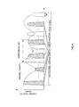
- FIG.1 illustrates a narrowband CQI and a wideband CQI.
- the overall system bandwidth is formed with a plurality of RBs.
- a mobile station measures a narrowband (subband) CQI by estimating for example SINR (Signal to Interference plus Noise Ratio), channel quality of two contiguous RBs, and measures a wideband CQI by estimating the channel quality of the overall system bandwidth.
- SINR Signal to Interference plus Noise Ratio
- Non-Patent Document 1 3GPP R1-073681, Nokia Siemens Networks, Nokia, "CQI reporting requirements for E-UTRA UE," 20th-24th August 2007
- Document EP 1 750 408 A2 relates to apparatus and method channel quality feedback in a muti-carrier wireless network.
- the subscriber station determines a total average signal level across N subbands, where each of subband comprises a plurality of subcarriers. It is described that the total average CQI value is calculated based on the entire bandwidth occupied by all of the subcarriers or based on a representative subset of the subcarriers.
- a mobile station needs to estimate channel quality of overall system bandwidth by corresponding to a plurality of system bandwidths, to measure a plurality of wideband CQIs. Further, to estimate channel quality, a mobile station requires decoding capacity to support all multiple transmission speeds of when a plurality of system bandwidths are each used. For example, the mobile station requires 30 Mbps decoding capacity to support the transmission speed upon using a 10 MHz system bandwidth. Consequently, the amount of processing required for the mobile station increases.
- FIG.2 shows a case as an example where a communication system provides three system bandwidths, 10 MHz, 5 MHz and 3 MHz.
- a CQI is represented by, for example, a TBS (Transport Block Size).
- TBS represents the number of information bits that can be transmitted while satisfying a predetermined packet error rate in the entire system bandwidth when communication is carried out with a channel SINR measured in the mobile station.
- the mobile station needs to hold CQI tables, in which TBSs are associated with CQI indices, corresponding to a plurality of system bandwidths (10 MHz, 5 MHz and 3 MHz), respectively.
- the mobile station finds a TBS value by channel estimation, generates a CQI index with reference to a CQI table associated with a system bandwidth, and feeds back the CQI index to the base station.
- the system band is 10 MHz (50 RBs)
- the mobile station performs channel estimation for a system bandwidth of 10 MHz, to acquire a TBS of 12000 bits as channel quality, and reports a CQI index associated with the TBS of 12000 bits to the base station.
- the system band is 5 MHz (25 RBs)
- the mobile station performs channel estimation for a system bandwidth of 5 MHz, to acquire a TBS of 6000 bits as channel quality, and reports a CQI index associated with the TBS of 6000 bits to the base station.
- the present invention attains the above object by means of a receiving apparatus according to claim 1 and of a method according to claim 7. Preferred embodiments are claimed in the dependent claims.
- the present invention it is possible to reduce the amount of processing in a receiving apparatus for measuring and reporting CQIs in a communication system providing a plurality of system bandwidths.
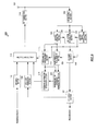
- FIG.3 is a block diagram showing the configuration of receiving apparatus 100 according to Embodiment 1 of the present invention.
- a mobile station apparatus is a concrete example of receiving apparatus 100 shown in FIG.3 , and receiving apparatus 100 supports a plurality of system bandwidths.
- RF receiving section 102 receives a signal transmitted from transmitting apparatus 150 (described later) via antenna 101, performs radio receiving processing including down-conversion and A/D conversion on the received signal, and, in the signal after radio receiving processing, outputs a pilot signal to channel estimation section 103, outputs a control signal to control signal demodulation section 104 and outputs a data signal to data signal demodulation section 105.
- Channel estimation section 103 calculates a channel estimation value (channel matrix) using the pilot signal outputted from RF receiving section 102, and outputs the calculated channel estimation value to data signal demodulation section 105, narrowband CQI measurement section 109 and wideband CQI measurement section 110.
- Control signal demodulation section 104 demodulates the control signal outputted from RF receiving section 102, outputs the system bandwidth included in the demodulated control signal to wideband CQI measurement section 110, outputs the narrow bandwidth start position to narrowband CQI measurement section 109, outputs the modulation scheme and coding rate to data signal demodulation section 105 and decoding section 106, respectively, and outputs resource allocation result to multiplexing section 113.
- the system bandwidth is 10 MHz
- the system bandwidth is shown in the number of RBs corresponding to 10 MHz
- the narrow bandwidth start position is shown in an RB number.
- Data signal demodulation section 105 demodulates the received signal outputted from RF receiving section 102 using the channel estimation value outputted from channel estimation section 103 and the modulation scheme outputted from control signal demodulation section 104, and outputs the demodulation result to decoding section 106.
- Decoding section 106 decodes the demodulation result outputted from data signal demodulation section 105 using the coding rate outputted from control signal demodulation section 104, and outputs the decoded data signal (decoded data) to CRC check section 107.
- CRC check section 107 performs a CRC check on the decoded data outputted from decoding section 106, to detect whether there is an error or not.
- CRC check section 107 outputs an error detection result of the decoded data to ACK/NACK generation section 108, and outputs decoded data without an error, as received data.
- ACK/NACK generation section 108 generates an ACK or NACK according to the error detection result of the decoded data outputted from CRC check section 107. That is, ACK/NACK generation section 108 generates an ACK if there is not an error, and generates a NACK if there is an error, and outputs the generated ACK/NACK to multiplexing section 113.
- narrowband CQI measurement section 109 Based on the channel matrix outputted from channel estimation section 103, narrowband CQI measurement section 109 measures the TBS in a the predetermined number of RBs for CQI measurement, that is, measures the narrow bandwidth TBS from the narrow bandwidth start position outputted from control signal demodulation section 104. Further, narrowband CQI measurement section 109, which holds a CQI table in which TBSs are associated with CQI indices, finds a CQI index associated with the measured narrow-bandwidth TBS, that is, finds a narrowband CQI index in the CQI table, and outputs the narrowband CQI index to feedback information generation section 111. The CQI measurement processing in narrowband CQI measurement section 109 will be described later in detail.
- Wideband CQI measurement section 1 1 0 extracts a predetermined number of RBs for CQI measurement from the system bandwidth outputted from control signal demodulation section 104, and measures the TBS for the extracted RBs based on the channel matrix outputted from channel estimation section 103. Further, wideband CQI measurement section 110, which holds the same CQI table as the CQI table held in narrowband CQI measurement section 109, finds a CQI index associated with the measured TBS in the measured system bandwidth, that is, finds a wideband CQI index in the CQI table, and outputs the wideband CQI index to feedback information generation section 111. The CQI measurement processing in wideband CQI measurement section 110 will be described later in detail.
- Feedback information generation section 111 generates feedback information including the narrowband CQI index outputted from narrowband CQI measurement section 109 and the wideband CQI index outputted from wideband CQI measurement section 110, and outputs the generated feedback information to multiplexing section 113.
- ACK/NACK generation section 108 and feedback information generation section III function as a control channel generation section.
- Encoding section 112 encodes transmission data and outputs the encoded transmission data to multiplexing section 113.
- Multiplexing section 113 forms a control channel with the ACK or NACK outputted from ACK/NACK generation section 108 and the feedback information outputted from feedback information generation section 111. Further, multiplexing section 113 multiplexes the formed control channel and the transmission data outputted from encoding section 112 based on the resource allocation result outputted from control signal demodulation section 104, and outputs the multiplexed signal to RF transmitting section 114.
- RF transmitting section 114 performs radio transmitting processing including D/A conversion and up-conversion on the signal outputted from multiplexing section 113, and outputs the signal after radio transmitting processing to transmitting apparatus 150 from antenna 101.
- FIG.4 explains the detail of the CQI measurement processing in narrowband CQI measurement section 109 and wideband CQI measurement section 110.
- the case will be explained as an example where the narrow bandwidth start position outputted from control signal demodulation section 104 to narrowband CQI measurement section 109 is the thirtieth RB and where the system bandwidth outputted from control signal demodulation section 104 to wideband CQI measurement section 110 is 10 MHz.
- the RBs shown in the diagonal lines are the RBs to equal the number of RBs for CQI measurement extracted from the system band of 10 MHz.
- the number of RBs in which a TBS is measured in narrowband CQI measurement section 109 and the number of RBs in which a TBS is measured in wideband CQI measurement section 110 are both the number of RBs for CQI measurement, for example, "5.”
- Wideband CQI measurement section 110 extracts RBs to equal the number of RBs for CQI measurement from the system bandwidth outputted from control signal demodulation section 104. For example, when the system bandwidth outputted from control signal demodulation section 104 is 10 MHz, which has 50 RBs, wideband CQI measurement section 110 extracts the first, eleventh, twenty-first, thirty-first, and forty-first RBs from the fifty RBs. Next, wideband CQI measurement section 110 finds SINRs per extracted RB using the channel estimation value of each subcarrier outputted from channel estimation section 103.
- wideband CQI measurement section 110 finds an average of the SINRs of the first, eleventh, twenty-first, thirty-first, and forty-first RBs and, based on this average value, calculates a possible TBS upon using resources equaling five RBs.
- wideband CQI measurement section 110 refers to a provided CQI table as shown in FIG.5 , finds a wideband CQI index associated with the calculated TBS, and outputs the wideband CQI index to feedback information generation section 111. For example, when the calculated TBS is 240 bits, wideband CQI measurement section 110 outputs "2" as the wideband CQI index to feedback information generation section 111.
- narrowband CQI measurement section 109 finds a TBS in RBs to equal the number of RBs for CQI measurement from the narrow bandwidth start position outputted from control signal demodulation section 104. For example, narrowband CQI measurement section 109 finds a TBS in the five RBs, the thirtieth to thirty-fourth RBs shown in FIG.4 . Then, narrowband CQI measurement section 109 finds a narrowband CQI index associated with the calculated TBS with reference to the provided CQI table as shown in FIG.5 , and outputs the narrowband CQI index to feedback information generation section 111.
- the number of RBs equal to or more than the lower limit of the system bandwidth in which TBS does not depend on the SINR is determined to be the number of RBs for CQI measurement in advance, by extracting RBs to equal the number of RBs for CQI measurement and by measuring a TBS, wideband CQI measurement section 110 is able to acquire a wideband CQI index showing channel quality of overall system bandwidth.
- wideband CQI measurement section 110 performs similar processing and is able to acquire a wideband CQI index. That is, regardless of the system bandwidth, wideband CQI measurement section 110 extracts RBs for CQI measurement and finds a wideband CQI index using the CQI table shown in FIG. 5 .
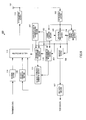
- FIG.6 is a block diagram showing the configuration of transmitting apparatus 150 according to Embodiment 1 of the present invention.
- a base station apparatus is a concrete example of transmitting apparatus 150 shown in FIG.6 , and transmitting apparatus 150 supports a plurality of system bandwidths.
- RF receiving section 152 receives a signal transmitted from receiving apparatus 100 via antenna 151, performs radio receiving processing including down-conversion and A/D conversion on the received signal, and outputs the signal after radio receiving processing to demultiplexing section 153.
- Demultiplexing section 153 demultiplexes the signal outputted from RF receiving section 152 into a wideband CQI index, a narrowband CQI index and an ACK or NACK and a data signal.
- Demultiplexing section 153 outputs the demultiplexed data signal to demodulation and decoding section 154, outputs the narrowband CQI index to narrowband CQI demodulation section 156, outputs the wideband CQI index to wideband CQI demodulation section 157 and outputs the ACK or NACK to encoding section 160.
- Demodulation and decoding section 154 demodulates and decodes the data signal outputted from demultiplexing section 153, and outputs the decoded data to CRC check section 155.
- CRC check section 155 performs a CRC check on the decoded data outputted from demodulation and decoding section 154, to detect whether or not there is an error, and outputs the decoded data without error as received data.
- Narrowband CQI demodulation section 156 demodulates the narrowband CQI index outputted from demultiplexing section 153. That is, narrowband CQI demodulation section 156 finds a TBS associated with the narrowband CQI index with reference to a CQI table and reads the TBS as information bits that can be transmitted with RBs to equal the number of RBs for CQI measurement. Narrowband CQI demodulation section 156 outputs this TBS as information used upon allocating resources in a narrow bandwidth, to resource allocation and MCS (Modulation and Coding Scheme) determination section 158.
- MCS Modulation and Coding Scheme
- Wideband CQI demodulation section 157 demodulates the wideband CQI index outputted from demultiplexing section 153. That is, wideband CQI demodulation section 157 finds a TBS associated with the wide band CQI index with reference to the CQI table and reads the TBS as information bits that can be transmitted with RBs to equal the number of RBs for CQI measurement. Wideband CQI demodulation section 157 outputs this TBS as information used upon allocating resources in overall system bandwidth, to resource allocation and MCS determination section 158.
- resource allocation and MCS determination section 158 Based on the TBSs outputted from narrowband CQI demodulation section 156 and wideband CQI demodulation section 157, resource allocation and MCS determination section 158 allocates resources formed with the RBs to equal the number of RBs for CQI measurement up to the number of RBs the overall system bandwidth, and outputs the resource allocation result to control signal generation section 159 and multiplexing section 162. Further, based on the TBSs outputted from narrowband CQI demodulation section 156 and wideband CQI demodulation section 157, resource allocation and MCS determination section 158 determines a coding rate and a modulation scheme, and outputs the determined coding rate and the determined modulation scheme to encoding section 160 and modulation section 161, respectively.
- Control signal generation section 159 generates a control signal using the system bandwidth, the narrow bandwidth start position, the resource allocation result the coding rate and the modulation scheme outputted from resource allocation and MCS determination section 158, and outputs the generated control signal to multiplexing section 162.
- Encoding section 160 encodes transmission data using the coding rate outputted from resource allocation and MCS determination section 158, and outputs, to modulation section 161, new transmission data or retransmission data depending on the ACK or NACK outputted from demultiplexing section 153. That is, when the ACK is acquired, encoding section 160 outputs new transmission data to modulation section 161, and, when the NACK is acquired, encoding section 160 outputs retransmission data to modulation section 161.
- Modulation section 161 modulates the transmission data outputted from encoding section 160 using the modulation scheme outputted from resource allocation and MCS determination section 158, and outputs the modulated transmission data to multiplexing section 162.
- Multiplexing section 162 multiplexes the transmission data outputted from modulation section 161 and the control signal outputted from control signal generation section 159 based on the resource allocation result outputted from resource allocation and MCS determination section 158, and outputs the multiplexed signal to RF transmitting section 163.
- RF transmitting section 163 performs radio transmitting processing including D/A conversion and up-conversion on the signal outputted from multiplexing section 162, and transmits the signal after radio transmitting processing to receiving apparatus 100 from antenna 151.
- step (hereinafter, simply "ST") 201 transmitting apparatus 150 transmits the pilot channel to receiving apparatus 100, and reports the narrow bandwidth start position and the wide bandwidth.
- narrowband CQI measurement section 109 in receiving apparatus 100 measures the narrowband CQI, to acquire the narrowband CQI index.
- wideband CQI measurement section 110 in receiving apparatus 100 measures the wideband CQI, to acquire the wideband CQI index.
- receiving apparatus 100 reports the narrowband CQI index and the wideband CQI index to transmitting apparatus 150.
- narrowband CQI demodulation section 156 in transmitting apparatus 150 demodulates the narrowband CQI index reported from receiving apparatus 100, to acquire the TBS associated with the narrowband CQI index.
- wideband CQI demodulation section 157 in transmitting apparatus 150 demodulates the wideband CQI index reported from receiving apparatus 100, to acquire the TBS associated with the wideband CQI index.
- resource allocation and MCS determination section 158 in transmitting apparatus 150 allocates resources and determines the coding rate and the modulation scheme.
- transmitting apparatus 150 transmits the pilot channel to receiving apparatus 100, reports the narrow bandwidth start position, system bandwidth, resource allocation result, and coding rate and modulation scheme in a control signal, and transmits the data signal.
- control signal demodulation section 104 in receiving apparatus 100 demodulates the control signal, and acquires the narrow bandwidth start position, system bandwidth, resource allocation result, and coding rate and modulation scheme.
- data signal demodulation section 105 in receiving apparatus 100 demodulates the data signal.
- decoding section 106 in receiving apparatus 100 decodes the data signal.
- ACK/NACK generation section 108 in receiving apparatus 100 generates an ACK signal or NACK signal.
- ST 213 the same operation is carried out as the operation in ST 202. That is, narrowband CQI measurement section 109 in receiving apparatus 100 measures the narrowband CQI, to acquire the narrowband CQI index.
- ST 214 the same operation is carried out as the operation in ST 203. That is, wideband CQI measurement section 110 in receiving apparatus 100 measures the wideband CQI, to acquire the wideband CQI index.
- receiving apparatus 100 transmits the data signal to transmitting apparatus 150, and reports the narrowband CQI index and the wideband CQI index.
- a receiving apparatus extracts the predetermined number of RBs from the overall system bandwidth regardless of a system bandwidth as long as the system bandwidth is equal to or more than a predetermined value, measures an average CQI from the extract RBs and reports the average CQI to a transmitting apparatus, so that it is possible to reduce the amount of processing for CQI measurement in the receiving apparatus.
- the present invention is not limited to this, and an overall system bandwidth may be used for the former number of RBs and the same value as the number of RBs for CQI measurement may be used for the latter number of RBs.
- the present invention is not limited to this, and, the transmitting apparatus may hold the number of RBs for CQI measurement, and may report the number of RBs for CQI measurement to the receiving apparatus.
- the present invention is not limited to this, and the transmitting apparatus and the receiving apparatus share the narrow bandwidth start position in advance.
- the number of narrowband widths in which a CQI is measured may be multiple, and, in this case, feedback information may be generated using an arbitrary information compression method.
- the present invention is not limited to this, and the narrowband CQI index and the wideband CQI index may be reported at different times.
- the wideband CQI index may be reported at longer cycles than the narrowband CQI index.
- FIG.8 is a block diagram showing the configuration of receiving apparatus 200 according to Embodiment 2 of the present invention.
- FIG.8 differs from FIG.3 in adding narrowband CQI difference representing section 201 and changing feedback information generation section 111 to feedback information generation section 211.
- narrowband CQI difference representing section 201 represents narrowband CQI index outputted from narrowband CQI measurement section 109 as a difference between the narrowband CQI index and wideband CQI index outputted from wideband CQI measurement section 1 10, and outputs this difference to feedback information generation section 211.
- Feedback information generation section 211 generates feedback information including the wideband CQI index outputted from wideband CQI measurement section 110 and the narrowband CQI difference representation outputted from narrowband CQI difference representing section 201, and outputs the generated feedback information to multiplexing section 113.
- the transmitting apparatus calculates a narrowband CQI index using the difference between the wideband CQI index and narrowband CQI index, and the wideband CQI index.
- the receiving apparatus represents a narrowband CQI index and a wideband CQI index shown in the same CQI table as a difference and feeds back the difference to the transmitting apparatus, so that it is possible to reduce the amount of feedback information and improve the throughput of the communication system.
- FIG.9 shows a block diagram showing the configuration of receiving apparatus 300 according to Embodiment 3 of the present invention.
- FIG.9 differs from FIG.3 in adding CQI measurement RB number holding section 301 and changing narrowband CQI measurement section 109 and wideband CQI measurement section 110 to narrowband CQI measurement section 309 and wideband CQI measurement section 310.
- CQI measurement RB number holding section 301 holds a table in which system bandwidths are associated with the numbers of RBs for CQI measurement.
- CQI measurement RB number holding section 301 finds the number of RBs for CQI measurement associated with the system bandwidth outputted from control signal demodulation section 104 with reference to the table, and outputs the number of RBs for CQI measurement to narrowband CQI measurement section 309 and wideband CQI measurement section 310.
- the system bandwidths are integral multiples of the number of RBs for CQI measurement.
- a greater system bandwidth is associated with a greater number of RBs for CQI measurement.
- the number of RBs for CQI measurement associated with the system bandwidth of 5 MHz or less is 5 RBs and the number of RBs for CQI measurement associated with the system bandwidth of 10 MHz or more is 10 RBs.
- Narrowband CQI measurement section 309 and wideband CQI measurement section 3 10 differ from narrowband CQI measurement section 109 and wideband CQI measurement section 110 in FIG.3 in only performing CQI measurement processing using the number of RBs for CQI measurement outputted from CQI measurement RB number holding section 301, instead of a predetermined number of RBs for CQI measurement.
- the receiving apparatus measures a CQI using the number of RBs for CQI measurement associated with a greater system bandwidth when the number of RBs for CQI measurement is greater, so that it is possible to reduce the amount of feedback and improve the accuracy of CQI measurement.
- the system bandwidths may be grouped into several groups, for example, depending on values of the bandwidths, and the numbers of RBs for CQI measurement may be individually associated with the groups.
- Embodiment 4 of the present invention an explanation will be given to the CQI measurement processing performed in a case where a system bandwidth is smaller than a bandwidth to equal the number of RBs for CQI measurement, for example, when the system bandwidth is 3 RBs.
- the system bandwidth is smaller than the bandwidth to equal the number of RBs for CQI measurement
- information bits that can be transmitted while satisfying a predetermined packet error rate, that is, the TBS depend on a SINR.
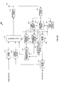
- FIG.10 is a block diagram showing the configuration of receiving apparatus 400 according to Embodiment 4 of the present invention.
- FIG.10 differs from FIG.3 in adding SINR versus TBS slope calculation section 401 and changing feedback information generation section 111 to feedback information generation section 411.
- SINR versus TBS slope calculation section 401 calculates a SINR vs TBS slope based on a channel estimation value received as input from channel estimation section 103, and outputs the calculated SINR vs TBS slope to feedback information generation section 411. For example, SINR versus TBS slope calculation section 401 calculates the ratio between the TBS in the bandwidth to equal the number of RBs for CQI measurement and the TBS in the system bandwidth or the difference between the TBS in the bandwidth to equal the number of RBs for CQI measurement and the TBS in the system bandwidth as the SINR vs TBS slope.
- Feedback information generation section 411 generates feedback information including the SINR vs TBS slope outputted from SINR versus TBS slope calculation section 401 and the narrowband CQI index outputted from narrowband CQI measurement section 109, and outputs the generated feedback information to multiplexing section 113.
- feedback information generation section 411 generates feedback information including the narrowband CQI index outputted from narrowband CQI measurement section 109 and the wideband CQI index outputted from wideband CQI measurement section 110, and outputs the generated feedback information to multiplexing section 113.
- FIG. 11 is a block diagram showing the configuration of transmitting apparatus 450 according to Embodiment 4 of the present invention.
- FIG.11 differs from FIG.6 in adding SINR versus TBS slope demodulation section 451 and changing resource allocation and MCS determination section 158 to resource allocation and MCS determination section 458.
- SINR versus TBS slope demodulation section 451 demodulates the SINR vs TBS slope outputted from demultiplexing section 153 and outputs the demodulated SINR vs TBS slope to resource allocation and MCS determination section 458.
- resource allocation and MCS determination section 458 estimates an increase in SINR requirement when the number of allocated RBs is small and does not satisfy the defined TBS, and commands RF transmitting section 163 to increase transmission power as necessary. Although, when the SINR requirement increases, transmission power is increased here, it is equally possible to reduce the number of bits when the SINR requirement increases, thereby increasing the coding gain.
- Embodiment 4 it is possible to increase flexibility to reduce the number of RBs upon allocating resources and secure the accuracy of link adaptation.
- Each function block employed in the description of each of the aforementioned embodiments may typically be implemented as an LSI constituted by an integrated circuit. These may be individual chips or partially or totally contained on a single chip. "LSI” is adopted here but this may also be referred to as “IC,” “system LSI,” “super LSI,” or “ultra LSI” depending on differing extents of integration.
- circuit integration is not limited to LSIs, and implementation using dedicated circuitry or general purpose processors is also possible.
- LSI manufacture utilization of a programmable FPGA (Field Programmable Gate Array) or a reconfigurable process or where connections and settings of circuit cells within an LSI can be reconfigured is also possible.
- FPGA Field Programmable Gate Array
- the receiving apparatus and the communication method according to the present invention is applicable to communication systems providing a plurality of system bandwidths, for example, mobile communication systems.
Description
- The present invention relates to a receiving apparatus and a communication method used in a radio communication system.
- In recent years, in OFDM (Orthogonal Frequency Division Multiplexing) scheme, studies are conducted for a technique of employing adaptive modulation and frequency scheduling in each RB (Resource Block) grouping a plurality of subcarriers, and improving spectrum efficiency. Adaptive modulation refers to a scheme for deciding coding rates and modulation schemes according to channel conditions observed on the receiving side so that a predetermined packet error rate is satisfied. With frequency scheduling, a plurality of mobile stations report channel conditions observed per RB on the receiving side, and the base station collects the channel conditions and allocates RBs to mobile stations according to a predetermined scheduling algorithm. Values used in these adaptive modulation and frequency scheduling for reporting channel conditions are called channel quality information (CQI: Channel Quality Indicator).
- As for CQI, parameters showing channel quality of contiguous RBs corresponding to the minimum unit of frequency scheduling are a "narrowband CQI," that is, a subband CQI, and parameters showing channel quality of overall system bandwidth are a "wideband CQI," that is, a system bandwidth CQI (see Non-Patent Document 1). A narrowband CQI is read as channel quality acquired in receiving processing in a mobile station when a base station allocates predetermined subbands, and is used for adaptive modulation of the subbands. Meanwhile, a wideband CQI is read as averaged channel quality acquired in receiving processing in a mobile station when a base station allocates arbitrary subbands, and used for adaptive modulation of arbitrary subbands.
FIG.1 illustrates a narrowband CQI and a wideband CQI. As shown inFIG.1 , the overall system bandwidth is formed with a plurality of RBs. Further, inFIG.1 , a mobile station measures a narrowband (subband) CQI by estimating for example SINR (Signal to Interference plus Noise Ratio), channel quality of two contiguous RBs, and measures a wideband CQI by estimating the channel quality of the overall system bandwidth.
Non-Patent Document 1: 3GPP R1-073681, Nokia Siemens Networks, Nokia, "CQI reporting requirements for E-UTRA UE," 20th-24th August 2007 -
Document EP 1 750 408 A2 relates to apparatus and method channel quality feedback in a muti-carrier wireless network. The subscriber station determines a total average signal level across N subbands, where each of subband comprises a plurality of subcarriers. It is described that the total average CQI value is calculated based on the entire bandwidth occupied by all of the subcarriers or based on a representative subset of the subcarriers. - However, in a communication system providing a plurality of bandwidths as system bandwidths like LTE (Long-Term Evolution), a mobile station needs to estimate channel quality of overall system bandwidth by corresponding to a plurality of system bandwidths, to measure a plurality of wideband CQIs. Further, to estimate channel quality, a mobile station requires decoding capacity to support all multiple transmission speeds of when a plurality of system bandwidths are each used. For example, the mobile station requires 30 Mbps decoding capacity to support the transmission speed upon using a 10 MHz system bandwidth. Consequently, the amount of processing required for the mobile station increases.
-
FIG.2 explains these problems.FIG.2 shows a case as an example where a communication system provides three system bandwidths, 10 MHz, 5 MHz and 3 MHz. Here, a CQI is represented by, for example, a TBS (Transport Block Size). TBS represents the number of information bits that can be transmitted while satisfying a predetermined packet error rate in the entire system bandwidth when communication is carried out with a channel SINR measured in the mobile station. The mobile station needs to hold CQI tables, in which TBSs are associated with CQI indices, corresponding to a plurality of system bandwidths (10 MHz, 5 MHz and 3 MHz), respectively. The mobile station finds a TBS value by channel estimation, generates a CQI index with reference to a CQI table associated with a system bandwidth, and feeds back the CQI index to the base station. For example, when the system band is 10 MHz (50 RBs), the mobile station performs channel estimation for a system bandwidth of 10 MHz, to acquire a TBS of 12000 bits as channel quality, and reports a CQI index associated with the TBS of 12000 bits to the base station. Further, when the system band is 5 MHz (25 RBs), the mobile station performs channel estimation for a system bandwidth of 5 MHz, to acquire a TBS of 6000 bits as channel quality, and reports a CQI index associated with the TBS of 6000 bits to the base station. - It is therefore an object of the present invention to provide a receiving apparatus and a communication method that are able to reduce the amount of processing for measuring and reporting CQIs in a communication system providing a plurality of system bandwidths.
- The present invention attains the above object by means of a receiving apparatus according to
claim 1 and of a method according to claim 7. Preferred embodiments are claimed in the dependent claims. - According to the present invention, it is possible to reduce the amount of processing in a receiving apparatus for measuring and reporting CQIs in a communication system providing a plurality of system bandwidths.
-
-
FIG.1 explains a narrowband CQI and a wideband CQI with related art; -
FIG.2 explains problems with related art; -
FIG.3 is a block diagram showing a configuration of the receiving apparatus according toEmbodiment 1 of the present invention; -
FIG.4 explains detail of the CQI measurement processing in the narrowband CQI measurement section and the wideband CQI measurement section according toEmbodiment 1 of the present invention; -
FIG.5 shows an example of a CQI table according toEmbodiment 1 of the present invention; -
FIG.6 is a block diagram showing a configuration of the transmitting apparatus according toEmbodiment 1 of the present invention; -
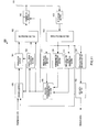
FIG.7 is a sequence diagram showing the operations of the receiving apparatus and the transmitting apparatus according toEmbodiment 1 of the present invention; -
FIG.8 is a block diagram showing a configuration of the receiving apparatus according toEmbodiment 2 of the present invention; -
FIG.9 is a block diagram showing a configuration of the receiving apparatus according toEmbodiment 3 of the present invention; -
FIG.10 is a block diagram showing a configuration of the receiving apparatus according toEmbodiment 4 of the present invention; and -
FIG. 11 is a block diagram showing a configuration of the transmitting apparatus according toEmbodiment 4 of the present invention. - In the following description, several embodiments are described. The embodiment corresponding to the claimed invention is
embodiment 3. - Further, in embodiments, the components having the same functions will be assigned to the same reference numerals and overlapping descriptions will be omitted.
-
FIG.3 is a block diagram showing the configuration of receivingapparatus 100 according toEmbodiment 1 of the present invention. A mobile station apparatus is a concrete example of receivingapparatus 100 shown inFIG.3 , and receivingapparatus 100 supports a plurality of system bandwidths. - In
FIG.3 ,RF receiving section 102 receives a signal transmitted from transmitting apparatus 150 (described later) viaantenna 101, performs radio receiving processing including down-conversion and A/D conversion on the received signal, and, in the signal after radio receiving processing, outputs a pilot signal tochannel estimation section 103, outputs a control signal to controlsignal demodulation section 104 and outputs a data signal to datasignal demodulation section 105. -
Channel estimation section 103 calculates a channel estimation value (channel matrix) using the pilot signal outputted fromRF receiving section 102, and outputs the calculated channel estimation value to datasignal demodulation section 105, narrowbandCQI measurement section 109 and widebandCQI measurement section 110. - Control
signal demodulation section 104 demodulates the control signal outputted fromRF receiving section 102, outputs the system bandwidth included in the demodulated control signal to widebandCQI measurement section 110, outputs the narrow bandwidth start position to narrowbandCQI measurement section 109, outputs the modulation scheme and coding rate to datasignal demodulation section 105 anddecoding section 106, respectively, and outputs resource allocation result tomultiplexing section 113. Here, if the system bandwidth is 10 MHz, the system bandwidth is shown in the number of RBs corresponding to 10 MHz, and the narrow bandwidth start position is shown in an RB number. - Data
signal demodulation section 105 demodulates the received signal outputted fromRF receiving section 102 using the channel estimation value outputted fromchannel estimation section 103 and the modulation scheme outputted from controlsignal demodulation section 104, and outputs the demodulation result todecoding section 106. -
Decoding section 106 decodes the demodulation result outputted from datasignal demodulation section 105 using the coding rate outputted from controlsignal demodulation section 104, and outputs the decoded data signal (decoded data) toCRC check section 107. -
CRC check section 107 performs a CRC check on the decoded data outputted fromdecoding section 106, to detect whether there is an error or not.CRC check section 107 outputs an error detection result of the decoded data to ACK/NACK generation section 108, and outputs decoded data without an error, as received data. - ACK/
NACK generation section 108 generates an ACK or NACK according to the error detection result of the decoded data outputted fromCRC check section 107. That is, ACK/NACK generation section 108 generates an ACK if there is not an error, and generates a NACK if there is an error, and outputs the generated ACK/NACK tomultiplexing section 113. - Based on the channel matrix outputted from
channel estimation section 103, narrowbandCQI measurement section 109 measures the TBS in a the predetermined number of RBs for CQI measurement, that is, measures the narrow bandwidth TBS from the narrow bandwidth start position outputted from controlsignal demodulation section 104. Further, narrowbandCQI measurement section 109, which holds a CQI table in which TBSs are associated with CQI indices, finds a CQI index associated with the measured narrow-bandwidth TBS, that is, finds a narrowband CQI index in the CQI table, and outputs the narrowband CQI index to feedbackinformation generation section 111. The CQI measurement processing in narrowbandCQI measurement section 109 will be described later in detail. - Wideband
CQI measurement section 1 1 0 extracts a predetermined number of RBs for CQI measurement from the system bandwidth outputted from controlsignal demodulation section 104, and measures the TBS for the extracted RBs based on the channel matrix outputted fromchannel estimation section 103. Further, widebandCQI measurement section 110, which holds the same CQI table as the CQI table held in narrowbandCQI measurement section 109, finds a CQI index associated with the measured TBS in the measured system bandwidth, that is, finds a wideband CQI index in the CQI table, and outputs the wideband CQI index to feedbackinformation generation section 111. The CQI measurement processing in widebandCQI measurement section 110 will be described later in detail. - Feedback
information generation section 111 generates feedback information including the narrowband CQI index outputted from narrowbandCQI measurement section 109 and the wideband CQI index outputted from widebandCQI measurement section 110, and outputs the generated feedback information tomultiplexing section 113. ACK/NACK generation section 108 and feedback information generation section III function as a control channel generation section. -
Encoding section 112 encodes transmission data and outputs the encoded transmission data to multiplexingsection 113. - Multiplexing
section 113 forms a control channel with the ACK or NACK outputted from ACK/NACK generation section 108 and the feedback information outputted from feedbackinformation generation section 111. Further, multiplexingsection 113 multiplexes the formed control channel and the transmission data outputted from encodingsection 112 based on the resource allocation result outputted from controlsignal demodulation section 104, and outputs the multiplexed signal toRF transmitting section 114. -
RF transmitting section 114 performs radio transmitting processing including D/A conversion and up-conversion on the signal outputted from multiplexingsection 113, and outputs the signal after radio transmitting processing to transmittingapparatus 150 fromantenna 101. - Now, the CQI measurement processing in narrowband
CQI measurement section 109 and widebandCQI measurement section 110 will be described in detail. -
FIG.4 explains the detail of the CQI measurement processing in narrowbandCQI measurement section 109 and widebandCQI measurement section 110. InFIG.4 , the case will be explained as an example where the narrow bandwidth start position outputted from controlsignal demodulation section 104 to narrowbandCQI measurement section 109 is the thirtieth RB and where the system bandwidth outputted from controlsignal demodulation section 104 to widebandCQI measurement section 110 is 10 MHz. InFIG.4 , the RBs shown in the diagonal lines are the RBs to equal the number of RBs for CQI measurement extracted from the system band of 10 MHz. - As shown in
FIG.4 , the number of RBs in which a TBS is measured in narrowbandCQI measurement section 109 and the number of RBs in which a TBS is measured in widebandCQI measurement section 110 are both the number of RBs for CQI measurement, for example, "5." - Wideband
CQI measurement section 110 extracts RBs to equal the number of RBs for CQI measurement from the system bandwidth outputted from controlsignal demodulation section 104. For example, when the system bandwidth outputted from controlsignal demodulation section 104 is 10 MHz, which has 50 RBs, widebandCQI measurement section 110 extracts the first, eleventh, twenty-first, thirty-first, and forty-first RBs from the fifty RBs. Next, widebandCQI measurement section 110 finds SINRs per extracted RB using the channel estimation value of each subcarrier outputted fromchannel estimation section 103. Next, widebandCQI measurement section 110 finds an average of the SINRs of the first, eleventh, twenty-first, thirty-first, and forty-first RBs and, based on this average value, calculates a possible TBS upon using resources equaling five RBs. Next, widebandCQI measurement section 110 refers to a provided CQI table as shown inFIG.5 , finds a wideband CQI index associated with the calculated TBS, and outputs the wideband CQI index to feedbackinformation generation section 111. For example, when the calculated TBS is 240 bits, widebandCQI measurement section 110 outputs "2" as the wideband CQI index to feedbackinformation generation section 111. - Meanwhile, narrowband
CQI measurement section 109 finds a TBS in RBs to equal the number of RBs for CQI measurement from the narrow bandwidth start position outputted from controlsignal demodulation section 104. For example, narrowbandCQI measurement section 109 finds a TBS in the five RBs, the thirtieth to thirty-fourth RBs shown inFIG.4 . Then, narrowbandCQI measurement section 109 finds a narrowband CQI index associated with the calculated TBS with reference to the provided CQI table as shown inFIG.5 , and outputs the narrowband CQI index to feedbackinformation generation section 111. - Now, in wideband
CQI measurement section 110, the reason that channel quality in the overall system bandwidth can be shown using the TBS for the number of extracted RBs for CQI measurement, will be explained below. Using turbo codes, when the system bandwidth exceeds a predetermined value, for example, 5 RBs, information bits that can be transmitted while satisfying a predetermined packet error rate, that is, TBS, does not depend on the SINR. Further, from the perspective of frequency diversity, when the bandwidth exceeds about 1 MHz (5 RBs), information bits that can be transmitted while satisfying a predetermined packet error rate, that is, TBS, do not depend on the SINR. - Consequently, the number of RBs equal to or more than the lower limit of the system bandwidth in which TBS does not depend on the SINR is determined to be the number of RBs for CQI measurement in advance, by extracting RBs to equal the number of RBs for CQI measurement and by measuring a TBS, wideband
CQI measurement section 110 is able to acquire a wideband CQI index showing channel quality of overall system bandwidth. Although, inFIG.4 , a case is explained as an example where the system bandwidth outputted from controlsignal demodulation section 104 is 10 MHz, if the system bandwidth outputted from controlsignal demodulation section 104 is not 10 MHz, and is equal to or more than a bandwidth to equal the number of RBs for CQI measurement, for example, 5 MHz or 3 MHz, widebandCQI measurement section 110 performs similar processing and is able to acquire a wideband CQI index. That is, regardless of the system bandwidth, widebandCQI measurement section 110 extracts RBs for CQI measurement and finds a wideband CQI index using the CQI table shown inFIG. 5 . -
FIG.6 is a block diagram showing the configuration of transmittingapparatus 150 according toEmbodiment 1 of the present invention. A base station apparatus is a concrete example of transmittingapparatus 150 shown inFIG.6 , and transmittingapparatus 150 supports a plurality of system bandwidths. - In
FIG.6 ,RF receiving section 152 receives a signal transmitted from receivingapparatus 100 viaantenna 151, performs radio receiving processing including down-conversion and A/D conversion on the received signal, and outputs the signal after radio receiving processing todemultiplexing section 153. -
Demultiplexing section 153 demultiplexes the signal outputted fromRF receiving section 152 into a wideband CQI index, a narrowband CQI index and an ACK or NACK and a data signal.Demultiplexing section 153 outputs the demultiplexed data signal to demodulation anddecoding section 154, outputs the narrowband CQI index to narrowbandCQI demodulation section 156, outputs the wideband CQI index to widebandCQI demodulation section 157 and outputs the ACK or NACK to encodingsection 160. - Demodulation and
decoding section 154 demodulates and decodes the data signal outputted fromdemultiplexing section 153, and outputs the decoded data toCRC check section 155. -
CRC check section 155 performs a CRC check on the decoded data outputted from demodulation anddecoding section 154, to detect whether or not there is an error, and outputs the decoded data without error as received data. - Narrowband
CQI demodulation section 156 demodulates the narrowband CQI index outputted fromdemultiplexing section 153. That is, narrowbandCQI demodulation section 156 finds a TBS associated with the narrowband CQI index with reference to a CQI table and reads the TBS as information bits that can be transmitted with RBs to equal the number of RBs for CQI measurement. NarrowbandCQI demodulation section 156 outputs this TBS as information used upon allocating resources in a narrow bandwidth, to resource allocation and MCS (Modulation and Coding Scheme)determination section 158. - Wideband
CQI demodulation section 157 demodulates the wideband CQI index outputted fromdemultiplexing section 153. That is, widebandCQI demodulation section 157 finds a TBS associated with the wide band CQI index with reference to the CQI table and reads the TBS as information bits that can be transmitted with RBs to equal the number of RBs for CQI measurement. WidebandCQI demodulation section 157 outputs this TBS as information used upon allocating resources in overall system bandwidth, to resource allocation andMCS determination section 158. - Based on the TBSs outputted from narrowband
CQI demodulation section 156 and widebandCQI demodulation section 157, resource allocation andMCS determination section 158 allocates resources formed with the RBs to equal the number of RBs for CQI measurement up to the number of RBs the overall system bandwidth, and outputs the resource allocation result to controlsignal generation section 159 andmultiplexing section 162. Further, based on the TBSs outputted from narrowbandCQI demodulation section 156 and widebandCQI demodulation section 157, resource allocation andMCS determination section 158 determines a coding rate and a modulation scheme, and outputs the determined coding rate and the determined modulation scheme toencoding section 160 andmodulation section 161, respectively. - Control
signal generation section 159 generates a control signal using the system bandwidth, the narrow bandwidth start position, the resource allocation result the coding rate and the modulation scheme outputted from resource allocation andMCS determination section 158, and outputs the generated control signal to multiplexingsection 162. -
Encoding section 160 encodes transmission data using the coding rate outputted from resource allocation andMCS determination section 158, and outputs, tomodulation section 161, new transmission data or retransmission data depending on the ACK or NACK outputted fromdemultiplexing section 153. That is, when the ACK is acquired, encodingsection 160 outputs new transmission data tomodulation section 161, and, when the NACK is acquired, encodingsection 160 outputs retransmission data tomodulation section 161. -
Modulation section 161 modulates the transmission data outputted from encodingsection 160 using the modulation scheme outputted from resource allocation andMCS determination section 158, and outputs the modulated transmission data to multiplexingsection 162. - Multiplexing
section 162 multiplexes the transmission data outputted frommodulation section 161 and the control signal outputted from controlsignal generation section 159 based on the resource allocation result outputted from resource allocation andMCS determination section 158, and outputs the multiplexed signal toRF transmitting section 163. -
RF transmitting section 163 performs radio transmitting processing including D/A conversion and up-conversion on the signal outputted from multiplexingsection 162, and transmits the signal after radio transmitting processing to receivingapparatus 100 fromantenna 151. - Next, the operations of the
above receiving apparatus 100 and transmittingapparatus 150 will be explained using the sequence diagram shown inFIG.7 . - In
FIG.7 , in step (hereinafter, simply "ST") 201, transmittingapparatus 150 transmits the pilot channel to receivingapparatus 100, and reports the narrow bandwidth start position and the wide bandwidth. - In ST 202, narrowband
CQI measurement section 109 in receivingapparatus 100 measures the narrowband CQI, to acquire the narrowband CQI index. - In ST 203, wideband
CQI measurement section 110 in receivingapparatus 100 measures the wideband CQI, to acquire the wideband CQI index. - In ST 204, receiving
apparatus 100 reports the narrowband CQI index and the wideband CQI index to transmittingapparatus 150. - In ST 205, narrowband
CQI demodulation section 156 in transmittingapparatus 150 demodulates the narrowband CQI index reported from receivingapparatus 100, to acquire the TBS associated with the narrowband CQI index. - In ST 206, wideband
CQI demodulation section 157 in transmittingapparatus 150 demodulates the wideband CQI index reported from receivingapparatus 100, to acquire the TBS associated with the wideband CQI index. - In ST 207, based on the TBSs, resource allocation and
MCS determination section 158 in transmittingapparatus 150 allocates resources and determines the coding rate and the modulation scheme. - In ST 208, transmitting
apparatus 150 transmits the pilot channel to receivingapparatus 100, reports the narrow bandwidth start position, system bandwidth, resource allocation result, and coding rate and modulation scheme in a control signal, and transmits the data signal. - In ST 209, control
signal demodulation section 104 in receivingapparatus 100 demodulates the control signal, and acquires the narrow bandwidth start position, system bandwidth, resource allocation result, and coding rate and modulation scheme. - In ST 210, data signal
demodulation section 105 in receivingapparatus 100 demodulates the data signal. - In
ST 211, decodingsection 106 in receivingapparatus 100 decodes the data signal. - In ST 212, based on the CRC check result in
CRC check section 107 in receivingapparatus 100, ACK/NACK generation section 108 in receivingapparatus 100 generates an ACK signal or NACK signal. - In ST 213, the same operation is carried out as the operation in ST 202. That is, narrowband
CQI measurement section 109 in receivingapparatus 100 measures the narrowband CQI, to acquire the narrowband CQI index. - In ST 214, the same operation is carried out as the operation in ST 203. That is, wideband
CQI measurement section 110 in receivingapparatus 100 measures the wideband CQI, to acquire the wideband CQI index. - In ST 215, receiving
apparatus 100 transmits the data signal to transmittingapparatus 150, and reports the narrowband CQI index and the wideband CQI index. - In this way, according to
Embodiment 1, a receiving apparatus extracts the predetermined number of RBs from the overall system bandwidth regardless of a system bandwidth as long as the system bandwidth is equal to or more than a predetermined value, measures an average CQI from the extract RBs and reports the average CQI to a transmitting apparatus, so that it is possible to reduce the amount of processing for CQI measurement in the receiving apparatus. - Although a case has been explained with the present embodiment as an example where, during CQI measurement processing in wideband
CQI measurement section 110, the number of RBs that are used for calculating an average SINR and the number of RBs upon converting the number of resources assumed when a possible TBS is calculated, are the same value, the present invention is not limited to this, and an overall system bandwidth may be used for the former number of RBs and the same value as the number of RBs for CQI measurement may be used for the latter number of RBs. - Further, although a case has been explained with the present embodiment as an example where both the receiving apparatus and the transmitting apparatus hold the predetermined number of RBs for CQI measurement, the present invention is not limited to this, and, the transmitting apparatus may hold the number of RBs for CQI measurement, and may report the number of RBs for CQI measurement to the receiving apparatus.
- Further, although a case has been explained with the present embodiment as an example where the transmitting apparatus reports the narrow bandwidth start position to the receiving apparatus using the control signal, the present invention is not limited to this, and the transmitting apparatus and the receiving apparatus share the narrow bandwidth start position in advance. Further, the number of narrowband widths in which a CQI is measured may be multiple, and, in this case, feedback information may be generated using an arbitrary information compression method.
- Further, although a case has been explained with the present embodiment where the narrowband CQI index and the wideband CQI index are reported at the same time from the receiving apparatus to the transmitting apparatus, the present invention is not limited to this, and the narrowband CQI index and the wideband CQI index may be reported at different times. For example, the wideband CQI index may be reported at longer cycles than the narrowband CQI index.
-
FIG.8 is a block diagram showing the configuration of receivingapparatus 200 according toEmbodiment 2 of the present invention.FIG.8 differs fromFIG.3 in adding narrowband CQIdifference representing section 201 and changing feedbackinformation generation section 111 to feedbackinformation generation section 211. - In
FIG.8 , narrowband CQIdifference representing section 201 represents narrowband CQI index outputted from narrowbandCQI measurement section 109 as a difference between the narrowband CQI index and wideband CQI index outputted from widebandCQI measurement section 1 10, and outputs this difference to feedbackinformation generation section 211. - Feedback
information generation section 211 generates feedback information including the wideband CQI index outputted from widebandCQI measurement section 110 and the narrowband CQI difference representation outputted from narrowband CQIdifference representing section 201, and outputs the generated feedback information tomultiplexing section 113. - Parallel to receiving
apparatus 200, the transmitting apparatus (not shown) according to the present embodiment calculates a narrowband CQI index using the difference between the wideband CQI index and narrowband CQI index, and the wideband CQI index. - In this way, according to
Embodiment 2, the receiving apparatus represents a narrowband CQI index and a wideband CQI index shown in the same CQI table as a difference and feeds back the difference to the transmitting apparatus, so that it is possible to reduce the amount of feedback information and improve the throughput of the communication system. -
FIG.9 shows a block diagram showing the configuration of receivingapparatus 300 according toEmbodiment 3 of the present invention.FIG.9 differs fromFIG.3 in adding CQI measurement RBnumber holding section 301 and changing narrowbandCQI measurement section 109 and widebandCQI measurement section 110 to narrowbandCQI measurement section 309 and widebandCQI measurement section 310. - In
FIG.9 , CQI measurement RBnumber holding section 301 holds a table in which system bandwidths are associated with the numbers of RBs for CQI measurement. CQI measurement RBnumber holding section 301 finds the number of RBs for CQI measurement associated with the system bandwidth outputted from controlsignal demodulation section 104 with reference to the table, and outputs the number of RBs for CQI measurement to narrowbandCQI measurement section 309 and widebandCQI measurement section 310. In the table held in CQI measurement RBnumber holding section 301, the system bandwidths are integral multiples of the number of RBs for CQI measurement. Further, in the table held in CQI measurement RBnumber holding section 301, a greater system bandwidth is associated with a greater number of RBs for CQI measurement. For example, the number of RBs for CQI measurement associated with the system bandwidth of 5 MHz or less is 5 RBs and the number of RBs for CQI measurement associated with the system bandwidth of 10 MHz or more is 10 RBs. - Narrowband
CQI measurement section 309 and widebandCQI measurement section 3 10 differ from narrowbandCQI measurement section 109 and widebandCQI measurement section 110 inFIG.3 in only performing CQI measurement processing using the number of RBs for CQI measurement outputted from CQI measurement RBnumber holding section 301, instead of a predetermined number of RBs for CQI measurement. - In this way, according to the present embodiment, the receiving apparatus measures a CQI using the number of RBs for CQI measurement associated with a greater system bandwidth when the number of RBs for CQI measurement is greater, so that it is possible to reduce the amount of feedback and improve the accuracy of CQI measurement.
- In the table held in CQI measurement RB
number holding section 301, the system bandwidths may be grouped into several groups, for example, depending on values of the bandwidths, and the numbers of RBs for CQI measurement may be individually associated with the groups. - In
Embodiment 4 of the present invention, an explanation will be given to the CQI measurement processing performed in a case where a system bandwidth is smaller than a bandwidth to equal the number of RBs for CQI measurement, for example, when the system bandwidth is 3 RBs. When the system bandwidth is smaller than the bandwidth to equal the number of RBs for CQI measurement, information bits that can be transmitted while satisfying a predetermined packet error rate, that is, the TBS, depend on a SINR. -
FIG.10 is a block diagram showing the configuration of receivingapparatus 400 according toEmbodiment 4 of the present invention.FIG.10 differs fromFIG.3 in adding SINR versus TBSslope calculation section 401 and changing feedbackinformation generation section 111 to feedbackinformation generation section 411. - In
FIG.10 , when a system bandwidth outputted from controlsignal demodulation section 104 is smaller than a bandwidth to equal the number of RBs for CQI measurement, SINR versus TBSslope calculation section 401 calculates a SINR vs TBS slope based on a channel estimation value received as input fromchannel estimation section 103, and outputs the calculated SINR vs TBS slope to feedbackinformation generation section 411. For example, SINR versus TBSslope calculation section 401 calculates the ratio between the TBS in the bandwidth to equal the number of RBs for CQI measurement and the TBS in the system bandwidth or the difference between the TBS in the bandwidth to equal the number of RBs for CQI measurement and the TBS in the system bandwidth as the SINR vs TBS slope. - Feedback
information generation section 411 generates feedback information including the SINR vs TBS slope outputted from SINR versus TBSslope calculation section 401 and the narrowband CQI index outputted from narrowbandCQI measurement section 109, and outputs the generated feedback information tomultiplexing section 113. Or feedbackinformation generation section 411 generates feedback information including the narrowband CQI index outputted from narrowbandCQI measurement section 109 and the wideband CQI index outputted from widebandCQI measurement section 110, and outputs the generated feedback information tomultiplexing section 113. -
FIG. 11 is a block diagram showing the configuration of transmittingapparatus 450 according toEmbodiment 4 of the present invention.FIG.11 differs fromFIG.6 in adding SINR versus TBSslope demodulation section 451 and changing resource allocation andMCS determination section 158 to resource allocation andMCS determination section 458. - SINR versus TBS
slope demodulation section 451 demodulates the SINR vs TBS slope outputted fromdemultiplexing section 153 and outputs the demodulated SINR vs TBS slope to resource allocation andMCS determination section 458. - Based on the SINR vs TBS slope outputted from SINR versus TBS
slope demodulation section 451, resource allocation andMCS determination section 458 estimates an increase in SINR requirement when the number of allocated RBs is small and does not satisfy the defined TBS, and commandsRF transmitting section 163 to increase transmission power as necessary. Although, when the SINR requirement increases, transmission power is increased here, it is equally possible to reduce the number of bits when the SINR requirement increases, thereby increasing the coding gain. - In this way, according to
Embodiment 4, it is possible to increase flexibility to reduce the number of RBs upon allocating resources and secure the accuracy of link adaptation. - Embodiments of the present invention have been described above.
- Further, although cases have been described with the above embodiment as examples where the present invention is configured by hardware, the present invention can also be realized by software.
- Each function block employed in the description of each of the aforementioned embodiments may typically be implemented as an LSI constituted by an integrated circuit. These may be individual chips or partially or totally contained on a single chip. "LSI" is adopted here but this may also be referred to as "IC," "system LSI," "super LSI," or "ultra LSI" depending on differing extents of integration.
- Further, the method of circuit integration is not limited to LSIs, and implementation using dedicated circuitry or general purpose processors is also possible. After LSI manufacture, utilization of a programmable FPGA (Field Programmable Gate Array) or a reconfigurable process or where connections and settings of circuit cells within an LSI can be reconfigured is also possible.
- Further, if integrated circuit technology comes out to replace LSIs as a result of the advancement of semiconductor technology or a derivative other technology, it is naturally also possible to carry out function block integration using this technology. Application of biotechnology is also possible.
- The receiving apparatus and the communication method according to the present invention is applicable to communication systems providing a plurality of system bandwidths, for example, mobile communication systems.
Claims (12)
- A receiving apparatus (100, 200, 300, 400) receiving data transmitted from a transmitting apparatus in a communication system where a plurality of system bandwidths are configured, said receiving apparatus comprising:a receiving unit (102, 104) configured to receive information related to the system bandwidth,a calculating unit (109, 110, 309, 310) configured to calculate on the basis of channel estimation, a possible subband transport block size for a subband which is a set of a predefined number of contiguous resource blocks depending on the system bandwidth, and a possible wideband transport block size for an entire system bandwidth, obtaining a corresponding subband CQI and wideband CQI using a relationship between transport block size and a corresponding CQI representing a channel quality, wherein each of the resource blocks is comprised of a plurality of consecutive subcarriers in a frequency domain and the predefined number of contiguous resource blocks used for calculating the subband transport block size is equal to the number of resource blocks extracted from the entire system bandwidth and used for calculating the wideband transport block size;a generating unit (111, 211, 411) configured to generate feedback information comprised of the subband CQI and the wideband CQI; anda transmitting unit (114) configured to transmit the feedback information to the transmitting apparatus,wherein said calculating unit (109, 110, 309, 310) is adapted to obtain the subband CQI and the wideband CQI using the same relationship, andwherein the predefined number is associated with the system bandwidth, and the larger the system bandwidth is, the larger the predefined number is.
- The receiving apparatus according to claim 1, wherein said calculating unit is configured to use the same relationship regardless of the plurality of the system bandwidths.
- The receiving apparatus according to claim 1, wherein a total number of resource blocks corresponding to the system bandwidth is an integer multiple of the predefined number.
- The receiving apparatus according to claim 1, wherein said receiving apparatus has the start position of the subband in common with the transmitting apparatus.
- The receiving apparatus according to claim 1, wherein said calculating unit is configured to output the subband CQI as a difference with respect to the wideband CQI.
- The receiving apparatus according to claim 1, wherein said calculating unit is adapted to group the plurality of system bandwidths
into groups depending on values of the system bandwidths, and to associate a predefined number of the resource blocks forming the subband with each of the groups. - A data communicating method in a communication system where a plurality of system bandwidths are configured, said method comprising:receiving information related to the system bandwidth,calculating, on the basis of channel estimation, a possible subband transport block size for a subband which is a set of a predefined number of contiguous resource blocks depending on the system bandwidth, and a possible wideband transport block size for an entire system bandwidth, obtaining a corresponding subband CQI and wideband CQI using a relationship between transport block size and a corresponding CQI representing a channel quality, wherein each of the resource blocks is comprised of a plurality of consecutive subcarriers in a frequency domain and the predefined number of contiguous resource blocks used for calculating the subband transport block size is equal to the number of resource blocks extracted from the entire system bandwidth and used for calculating the wideband transport block size;generating feedback information comprised of the subband CQI and the wideband CQI;andreporting the feedback information,wherein the subband CQI and the wideband CQI are obtained using the same relationship, andwherein the predefined number is associated with the system bandwidth, and the larger the system bandwidth is, the larger the predefined number is.
- The data communicating method according to claim 7, wherein the same relationship is used regardless of the system bandwidths.
- The data communicating method according to claim 7, wherein a total number of resource blocks corresponding to the system bandwidth is an integer multiple of the predefined number.
- The data communicating method according to claim 7, wherein the start position of the subband is in common with a communication party to which the feedback information is reported.
- The data communicating method according to claim 7, wherein the subband CQI is output as a difference with respect to the wideband CQI.
- The data communicating method according to claim 7, wherein the plurality of system bandwidths are grouped into groups depending on values of the system bandwidths, and a predefined number of the resource blocks forming the subband is associated with each of the groups.
Priority Applications (1)
| Application Number | Priority Date | Filing Date | Title |
|---|---|---|---|
| EP20110186149 EP2410782B1 (en) | 2007-10-01 | 2008-09-30 | Receiver apparatus and communication method |
Applications Claiming Priority (2)
| Application Number | Priority Date | Filing Date | Title |
|---|---|---|---|
| JP2007257779 | 2007-10-01 | ||
| PCT/JP2008/002737 WO2009044536A1 (en) | 2007-10-01 | 2008-09-30 | Receiver apparatus and communication method |
Related Child Applications (1)
| Application Number | Title | Priority Date | Filing Date |
|---|---|---|---|
| EP11186149.8 Division-Into | 2011-10-21 |
Publications (3)
| Publication Number | Publication Date |
|---|---|
| EP2205017A1 EP2205017A1 (en) | 2010-07-07 |
| EP2205017A4 EP2205017A4 (en) | 2010-11-17 |
| EP2205017B1 true EP2205017B1 (en) | 2012-11-07 |
Family
ID=40525968
Family Applications (2)
| Application Number | Title | Priority Date | Filing Date |
|---|---|---|---|
| EP20080835514 Active EP2205017B1 (en) | 2007-10-01 | 2008-09-30 | Receiver apparatus and communication method |
| EP20110186149 Active EP2410782B1 (en) | 2007-10-01 | 2008-09-30 | Receiver apparatus and communication method |
Family Applications After (1)
| Application Number | Title | Priority Date | Filing Date |
|---|---|---|---|
| EP20110186149 Active EP2410782B1 (en) | 2007-10-01 | 2008-09-30 | Receiver apparatus and communication method |
Country Status (9)
| Country | Link |
|---|---|
| US (4) | US7970001B2 (en) |
| EP (2) | EP2205017B1 (en) |
| JP (5) | JP4615062B2 (en) |
| KR (1) | KR101473041B1 (en) |
| CN (3) | CN103957077B (en) |
| AU (1) | AU2008308378B2 (en) |
| BR (1) | BRPI0817596B1 (en) |
| RU (1) | RU2490820C2 (en) |
| WO (1) | WO2009044536A1 (en) |
Families Citing this family (31)
| Publication number | Priority date | Publication date | Assignee | Title |
|---|---|---|---|---|
| KR101473041B1 (en) * | 2007-10-01 | 2014-12-15 | 파나소닉 인텔렉츄얼 프로퍼티 코포레이션 오브 아메리카 | Receiver apparatus, transmitter apparatus and data communication method |
| KR20100093053A (en) * | 2007-10-30 | 2010-08-24 | 가부시키가이샤 엔티티 도코모 | User device and signal electric power measurement method |
| JP4893618B2 (en) * | 2007-12-27 | 2012-03-07 | 富士通東芝モバイルコミュニケーションズ株式会社 | Mobile radio terminal apparatus and mobile communication system |
| CN103560866B (en) | 2008-01-04 | 2017-04-05 | 知识产权之桥一号有限责任公司 | Radio communication device, wireless communications method and integrated circuit |
| US8301177B2 (en) * | 2009-03-03 | 2012-10-30 | Intel Corporation | Efficient paging operation for femtocell deployment |
| JP2010263256A (en) * | 2009-04-28 | 2010-11-18 | Ntt Docomo Inc | Mobile station and mobile communication system |
| WO2010140347A1 (en) * | 2009-06-02 | 2010-12-09 | シャープ株式会社 | Wireless communication system, wireless communication method, base station apparatus, and terminal station apparatus |
| JP5331593B2 (en) * | 2009-06-25 | 2013-10-30 | 京セラ株式会社 | Radio base station and resource allocation method |
| US8315183B2 (en) * | 2009-12-23 | 2012-11-20 | Intel Corporation | Channel quality indexing and reverse indexing |
| US8630311B2 (en) * | 2010-05-10 | 2014-01-14 | Futurewei Technologies, Inc. | System and method for reporting quantized feedback information for adaptive codebooks |
| JP5451675B2 (en) * | 2011-04-04 | 2014-03-26 | 株式会社Nttドコモ | Mobile device and method |
| US9755794B2 (en) * | 2011-05-10 | 2017-09-05 | Telefonaktiebolaget Lm Ericsson (Publ) | Methods and arrangements for handling a scheduling of a narrowband transmission in a cellular network |
| ITTO20110906A1 (en) * | 2011-10-11 | 2013-04-12 | Csp A Innovazione Nelle Ict Scarl | METHOD AND SYSTEM TO GENERATE A MODULAR SIGNAL AS WELL AS METHOD AND SYSTEM TO PROCESS A MODULAR SIGNAL |
| EP2811781A4 (en) * | 2012-02-01 | 2015-07-08 | Fujitsu Ltd | Wireless communication system, wireless terminal, wireless base station, and wireless communication method |
| US9648601B2 (en) | 2012-08-24 | 2017-05-09 | Sun Patent Trust | Communication method, base station and user equipment using a set of legacy or aggressive CQI table and legacy or aggressive MCS table |
| US9294935B2 (en) | 2012-08-30 | 2016-03-22 | Qualcomm Incorporated | Apparatus and method for exploiting frequency diversity for neighboring cell measurements |
| WO2014073487A1 (en) * | 2012-11-06 | 2014-05-15 | 京セラ株式会社 | Communication control method, base station, and processor |
| EP2922334B1 (en) * | 2012-11-19 | 2019-06-26 | LG Electronics Inc. | Method of reporting measurement in wireless communication system and device for supporting said method |
| US9712306B2 (en) | 2013-01-21 | 2017-07-18 | Apple Inc. | Adaptive link adaptation for wireless communications |
| WO2014139159A1 (en) * | 2013-03-15 | 2014-09-18 | Qualcomm Incorporated | Predicting channel state |
| WO2014183286A1 (en) * | 2013-05-16 | 2014-11-20 | Telefonaktiebolaget L M Ericsson (Publ) | Method and apparatus for rank override |
| CN110351870B (en) * | 2013-12-31 | 2021-12-10 | 华为技术有限公司 | Method and apparatus for measuring channel state information |
| JP2015185932A (en) * | 2014-03-20 | 2015-10-22 | 株式会社Nttドコモ | User terminal, radio base station, and radio communication method |
| US9949263B2 (en) * | 2015-02-25 | 2018-04-17 | Qualcomm Incorporated | Frequency resource allocation for a narrow-band cellular internet of things system |
| WO2016163819A1 (en) * | 2015-04-08 | 2016-10-13 | 엘지전자 주식회사 | Method for reporting channel state and apparatus therefor |
| US10728784B2 (en) * | 2015-10-23 | 2020-07-28 | Lg Electronics Inc. | Method and apparatus for defining wideband CQI in wireless communication system |
| JP2016189591A (en) * | 2016-05-02 | 2016-11-04 | 富士通株式会社 | Information feedback method, user device, and base station |
| WO2018126456A1 (en) | 2017-01-06 | 2018-07-12 | 广东欧珀移动通信有限公司 | Measurement method, base station and terminal |
| US11469806B2 (en) * | 2017-09-15 | 2022-10-11 | Apple Inc. | CSI measurement and feedback for eMTC-U system |
| CN110582075B (en) * | 2018-06-07 | 2022-11-29 | 中国电信股份有限公司 | Narrow-band Internet of things signal measuring method and system and application client |
| CN111050349B (en) * | 2018-10-12 | 2021-12-03 | 华为技术有限公司 | Method, device and system for determining channel quality information |
Family Cites Families (25)
| Publication number | Priority date | Publication date | Assignee | Title |
|---|---|---|---|---|
| US7050759B2 (en) * | 2002-02-19 | 2006-05-23 | Qualcomm Incorporated | Channel quality feedback mechanism and method |
| US7289452B2 (en) * | 2002-10-24 | 2007-10-30 | Nokia Corporation | Transport block size (TBS) signaling enhancement |
| KR20050119590A (en) * | 2004-06-16 | 2005-12-21 | 삼성전자주식회사 | Apparatus and method for feedback of channel quality information in a communication system using orthogonal frequency division multiplexing scheme |
| US7317702B2 (en) * | 2004-07-30 | 2008-01-08 | Lucent Technologies Inc. | Method and apparatus for enhancing performance of channel quality indicator (CQI) channel in wireless communications system |
| JP4457868B2 (en) * | 2004-11-25 | 2010-04-28 | 富士通株式会社 | Wireless communication device, mobile station |
| US7548752B2 (en) * | 2004-12-22 | 2009-06-16 | Qualcomm Incorporated | Feedback to support restrictive reuse |
| US7872981B2 (en) * | 2005-05-12 | 2011-01-18 | Qualcomm Incorporated | Rate selection for eigensteering in a MIMO communication system |
| KR101124932B1 (en) * | 2005-05-30 | 2012-03-28 | 삼성전자주식회사 | Apparatus and method for transmitting/receiving a data in mobile communication system with array antennas |
| US8229448B2 (en) * | 2005-08-01 | 2012-07-24 | Samsung Electronics Co., Ltd. | Apparatus and method for adaptive channel quality feedback in a multicarrier wireless network |
| US7457588B2 (en) * | 2005-08-01 | 2008-11-25 | Motorola, Inc. | Channel quality indicator for time, frequency and spatial channel in terrestrial radio access network |
| KR101119281B1 (en) * | 2005-08-29 | 2012-03-15 | 삼성전자주식회사 | Apparatus and method of feedback channel quality information and scheduling apparatus and method using thereof in a wireless communication system |
| KR20070027844A (en) * | 2005-08-29 | 2007-03-12 | 삼성전자주식회사 | Method and apparatus for transmitting channel quality information in a wireless communication system |
| US8054894B2 (en) | 2005-10-31 | 2011-11-08 | Motorola Mobility, Inc. | Method and apparatus for providing channel quality feedback in an orthogonal frequency division multiplexing communication system |
| JP4661532B2 (en) * | 2005-11-02 | 2011-03-30 | 日本電気株式会社 | Mobile communication system, mobile station, and decoding control method thereof |
| US20070177501A1 (en) * | 2006-01-31 | 2007-08-02 | Texas Instruments Incorporated | Signaling Requirements to Support Interference Coordination in OFDMA Based Systems |
| KR101002897B1 (en) | 2006-02-15 | 2010-12-21 | 한국과학기술원 | System and method for allocating a channel in a communication system |
| CN101039165B (en) * | 2006-03-14 | 2011-07-06 | 华为技术有限公司 | Information feedback method based on multi-antenna self-adaptive modulation coding and apparatus thereof |
| JP2007257779A (en) | 2006-03-24 | 2007-10-04 | Fujitsu Ltd | Control device, storage device, and head control method |
| US8014455B2 (en) * | 2006-03-27 | 2011-09-06 | Qualcomm Incorporated | Feedback of differentially encoded channel state information for multiple-input multiple-output (MIMO) and subband scheduling in a wireless communication system |
| JP2007274159A (en) * | 2006-03-30 | 2007-10-18 | Toshiba Corp | Base station, wireless terminal, and wireless communication method |
| US20080026744A1 (en) * | 2006-07-27 | 2008-01-31 | Nokia Corporation | Providing dynamically controlled CQI technique adapted for available signaling capacity |
| WO2008051038A1 (en) * | 2006-10-26 | 2008-05-02 | Lg Electronics Inc. | Method for reporting channel information in multiple antenna system |
| CN103152135B (en) * | 2007-04-30 | 2017-04-12 | 交互数字技术公司 | Feedback method in wireless transmit receive unit (WTRU) and WTRU |
| US8526371B2 (en) * | 2007-08-13 | 2013-09-03 | Qualcomm Incorporated | Frequency diverse transmissions in a wireless communication system |
| KR101473041B1 (en) * | 2007-10-01 | 2014-12-15 | 파나소닉 인텔렉츄얼 프로퍼티 코포레이션 오브 아메리카 | Receiver apparatus, transmitter apparatus and data communication method |
-
2008
- 2008-09-30 KR KR1020107007036A patent/KR101473041B1/en active IP Right Grant
- 2008-09-30 EP EP20080835514 patent/EP2205017B1/en active Active
- 2008-09-30 BR BRPI0817596-9A patent/BRPI0817596B1/en active IP Right Grant
- 2008-09-30 AU AU2008308378A patent/AU2008308378B2/en active Active
- 2008-09-30 CN CN201410166528.6A patent/CN103957077B/en active Active
- 2008-09-30 JP JP2009535968A patent/JP4615062B2/en active Active
- 2008-09-30 CN CN200880109566.0A patent/CN101809919B/en active Active
- 2008-09-30 EP EP20110186149 patent/EP2410782B1/en active Active
- 2008-09-30 US US12/680,182 patent/US7970001B2/en active Active
- 2008-09-30 RU RU2010112602/07A patent/RU2490820C2/en active
- 2008-09-30 CN CN201410164554.5A patent/CN103905158B/en active Active
- 2008-09-30 WO PCT/JP2008/002737 patent/WO2009044536A1/en active Application Filing
-
2010
- 2010-08-27 JP JP2010190885A patent/JP4652483B2/en active Active
- 2010-10-14 JP JP2010231809A patent/JP4653256B2/en active Active
- 2010-12-13 JP JP2010276921A patent/JP4698764B2/en active Active
-
2011
- 2011-01-04 US US12/984,555 patent/US8139547B2/en active Active
- 2011-01-04 US US12/984,559 patent/US8160087B2/en active Active
- 2011-02-25 JP JP2011040333A patent/JP5079111B2/en active Active
- 2011-05-12 US US13/106,314 patent/US8406189B2/en active Active
Also Published As
Similar Documents
| Publication | Publication Date | Title |
|---|---|---|
| EP2205017B1 (en) | Receiver apparatus and communication method | |
| US11233598B2 (en) | Radio transmission device and method | |
| US9967078B2 (en) | Wireless communication apparatus and wireless communication method | |
| DK2400807T3 (en) | SCHEDULING APPARATUS AND IDS PLANNING PROCEDURE |
Legal Events
| Date | Code | Title | Description |
|---|---|---|---|
| PUAI | Public reference made under article 153(3) epc to a published international application that has entered the european phase |
Free format text: ORIGINAL CODE: 0009012 |
|
| 17P | Request for examination filed |
Effective date: 20100322 |
|
| AK | Designated contracting states |
Kind code of ref document: A1 Designated state(s): AT BE BG CH CY CZ DE DK EE ES FI FR GB GR HR HU IE IS IT LI LT LU LV MC MT NL NO PL PT RO SE SI SK TR |
|
| AX | Request for extension of the european patent |
Extension state: AL BA MK RS |
|
| A4 | Supplementary search report drawn up and despatched |
Effective date: 20101019 |
|
| RIC1 | Information provided on ipc code assigned before grant |
Ipc: H04J 1/00 20060101ALI20101013BHEP Ipc: H04W 24/00 20090101AFI20090427BHEP Ipc: H04J 11/00 20060101ALI20101013BHEP Ipc: H04L 1/00 20060101ALI20101013BHEP Ipc: H04B 17/00 20060101ALI20101013BHEP Ipc: H04W 72/08 20090101ALI20101013BHEP |
|
| DAX | Request for extension of the european patent (deleted) | ||
| 17Q | First examination report despatched |
Effective date: 20110718 |
|
| GRAP | Despatch of communication of intention to grant a patent |
Free format text: ORIGINAL CODE: EPIDOSNIGR1 |
|
| GRAS | Grant fee paid |
Free format text: ORIGINAL CODE: EPIDOSNIGR3 |
|
| GRAA | (expected) grant |
Free format text: ORIGINAL CODE: 0009210 |
|
| AK | Designated contracting states |
Kind code of ref document: B1 Designated state(s): AT BE BG CH CY CZ DE DK EE ES FI FR GB GR HR HU IE IS IT LI LT LU LV MC MT NL NO PL PT RO SE SI SK TR |
|
| REG | Reference to a national code |
Ref country code: GB Ref legal event code: FG4D |
|
| REG | Reference to a national code |
Ref country code: CH Ref legal event code: EP Ref country code: AT Ref legal event code: REF Ref document number: 583423 Country of ref document: AT Kind code of ref document: T Effective date: 20121115 |
|
| REG | Reference to a national code |
Ref country code: IE Ref legal event code: FG4D |
|
| REG | Reference to a national code |
Ref country code: DE Ref legal event code: R096 Ref document number: 602008020004 Country of ref document: DE Effective date: 20130103 |
|
| REG | Reference to a national code |
Ref country code: AT Ref legal event code: MK05 Ref document number: 583423 Country of ref document: AT Kind code of ref document: T Effective date: 20121107 |
|
| REG | Reference to a national code |
Ref country code: NL Ref legal event code: VDEP Effective date: 20121107 |
|
| REG | Reference to a national code |
Ref country code: LT Ref legal event code: MG4D |
|
| PG25 | Lapsed in a contracting state [announced via postgrant information from national office to epo] |
Ref country code: HR Free format text: LAPSE BECAUSE OF FAILURE TO SUBMIT A TRANSLATION OF THE DESCRIPTION OR TO PAY THE FEE WITHIN THE PRESCRIBED TIME-LIMIT Effective date: 20121107 Ref country code: FI Free format text: LAPSE BECAUSE OF FAILURE TO SUBMIT A TRANSLATION OF THE DESCRIPTION OR TO PAY THE FEE WITHIN THE PRESCRIBED TIME-LIMIT Effective date: 20121107 Ref country code: NO Free format text: LAPSE BECAUSE OF FAILURE TO SUBMIT A TRANSLATION OF THE DESCRIPTION OR TO PAY THE FEE WITHIN THE PRESCRIBED TIME-LIMIT Effective date: 20130207 Ref country code: NL Free format text: LAPSE BECAUSE OF FAILURE TO SUBMIT A TRANSLATION OF THE DESCRIPTION OR TO PAY THE FEE WITHIN THE PRESCRIBED TIME-LIMIT Effective date: 20121107 Ref country code: SE Free format text: LAPSE BECAUSE OF FAILURE TO SUBMIT A TRANSLATION OF THE DESCRIPTION OR TO PAY THE FEE WITHIN THE PRESCRIBED TIME-LIMIT Effective date: 20121107 Ref country code: LT Free format text: LAPSE BECAUSE OF FAILURE TO SUBMIT A TRANSLATION OF THE DESCRIPTION OR TO PAY THE FEE WITHIN THE PRESCRIBED TIME-LIMIT Effective date: 20121107 Ref country code: ES Free format text: LAPSE BECAUSE OF FAILURE TO SUBMIT A TRANSLATION OF THE DESCRIPTION OR TO PAY THE FEE WITHIN THE PRESCRIBED TIME-LIMIT Effective date: 20130218 Ref country code: IS Free format text: LAPSE BECAUSE OF FAILURE TO SUBMIT A TRANSLATION OF THE DESCRIPTION OR TO PAY THE FEE WITHIN THE PRESCRIBED TIME-LIMIT Effective date: 20130307 |
|
| PG25 | Lapsed in a contracting state [announced via postgrant information from national office to epo] |
Ref country code: PL Free format text: LAPSE BECAUSE OF FAILURE TO SUBMIT A TRANSLATION OF THE DESCRIPTION OR TO PAY THE FEE WITHIN THE PRESCRIBED TIME-LIMIT Effective date: 20121107 Ref country code: GR Free format text: LAPSE BECAUSE OF FAILURE TO SUBMIT A TRANSLATION OF THE DESCRIPTION OR TO PAY THE FEE WITHIN THE PRESCRIBED TIME-LIMIT Effective date: 20130208 Ref country code: LV Free format text: LAPSE BECAUSE OF FAILURE TO SUBMIT A TRANSLATION OF THE DESCRIPTION OR TO PAY THE FEE WITHIN THE PRESCRIBED TIME-LIMIT Effective date: 20121107 Ref country code: PT Free format text: LAPSE BECAUSE OF FAILURE TO SUBMIT A TRANSLATION OF THE DESCRIPTION OR TO PAY THE FEE WITHIN THE PRESCRIBED TIME-LIMIT Effective date: 20130307 Ref country code: BE Free format text: LAPSE BECAUSE OF FAILURE TO SUBMIT A TRANSLATION OF THE DESCRIPTION OR TO PAY THE FEE WITHIN THE PRESCRIBED TIME-LIMIT Effective date: 20121107 Ref country code: SI Free format text: LAPSE BECAUSE OF FAILURE TO SUBMIT A TRANSLATION OF THE DESCRIPTION OR TO PAY THE FEE WITHIN THE PRESCRIBED TIME-LIMIT Effective date: 20121107 |
|
| PG25 | Lapsed in a contracting state [announced via postgrant information from national office to epo] |
Ref country code: AT Free format text: LAPSE BECAUSE OF FAILURE TO SUBMIT A TRANSLATION OF THE DESCRIPTION OR TO PAY THE FEE WITHIN THE PRESCRIBED TIME-LIMIT Effective date: 20121107 |
|
| PG25 | Lapsed in a contracting state [announced via postgrant information from national office to epo] |
Ref country code: BG Free format text: LAPSE BECAUSE OF FAILURE TO SUBMIT A TRANSLATION OF THE DESCRIPTION OR TO PAY THE FEE WITHIN THE PRESCRIBED TIME-LIMIT Effective date: 20130207 Ref country code: EE Free format text: LAPSE BECAUSE OF FAILURE TO SUBMIT A TRANSLATION OF THE DESCRIPTION OR TO PAY THE FEE WITHIN THE PRESCRIBED TIME-LIMIT Effective date: 20121107 Ref country code: CZ Free format text: LAPSE BECAUSE OF FAILURE TO SUBMIT A TRANSLATION OF THE DESCRIPTION OR TO PAY THE FEE WITHIN THE PRESCRIBED TIME-LIMIT Effective date: 20121107 Ref country code: SK Free format text: LAPSE BECAUSE OF FAILURE TO SUBMIT A TRANSLATION OF THE DESCRIPTION OR TO PAY THE FEE WITHIN THE PRESCRIBED TIME-LIMIT Effective date: 20121107 Ref country code: DK Free format text: LAPSE BECAUSE OF FAILURE TO SUBMIT A TRANSLATION OF THE DESCRIPTION OR TO PAY THE FEE WITHIN THE PRESCRIBED TIME-LIMIT Effective date: 20121107 |
|
| PG25 | Lapsed in a contracting state [announced via postgrant information from national office to epo] |
Ref country code: IT Free format text: LAPSE BECAUSE OF FAILURE TO SUBMIT A TRANSLATION OF THE DESCRIPTION OR TO PAY THE FEE WITHIN THE PRESCRIBED TIME-LIMIT Effective date: 20121107 Ref country code: RO Free format text: LAPSE BECAUSE OF FAILURE TO SUBMIT A TRANSLATION OF THE DESCRIPTION OR TO PAY THE FEE WITHIN THE PRESCRIBED TIME-LIMIT Effective date: 20121107 |
|
| PLBE | No opposition filed within time limit |
Free format text: ORIGINAL CODE: 0009261 |
|
| STAA | Information on the status of an ep patent application or granted ep patent |
Free format text: STATUS: NO OPPOSITION FILED WITHIN TIME LIMIT |
|
| 26N | No opposition filed |
Effective date: 20130808 |
|
| PG25 | Lapsed in a contracting state [announced via postgrant information from national office to epo] |
Ref country code: CY Free format text: LAPSE BECAUSE OF FAILURE TO SUBMIT A TRANSLATION OF THE DESCRIPTION OR TO PAY THE FEE WITHIN THE PRESCRIBED TIME-LIMIT Effective date: 20121107 |
|
| REG | Reference to a national code |
Ref country code: DE Ref legal event code: R097 Ref document number: 602008020004 Country of ref document: DE Effective date: 20130808 |
|
| PG25 | Lapsed in a contracting state [announced via postgrant information from national office to epo] |
Ref country code: MC Free format text: LAPSE BECAUSE OF FAILURE TO SUBMIT A TRANSLATION OF THE DESCRIPTION OR TO PAY THE FEE WITHIN THE PRESCRIBED TIME-LIMIT Effective date: 20121107 |
|
| REG | Reference to a national code |
Ref country code: CH Ref legal event code: PL |
|
| GBPC | Gb: european patent ceased through non-payment of renewal fee |
Effective date: 20130930 |
|
| REG | Reference to a national code |
Ref country code: FR Ref legal event code: ST Effective date: 20140530 |
|
| REG | Reference to a national code |
Ref country code: IE Ref legal event code: MM4A |
|
| REG | Reference to a national code |
Ref country code: DE Ref legal event code: R082 Ref document number: 602008020004 Country of ref document: DE Representative=s name: GRUENECKER, KINKELDEY, STOCKMAIR & SCHWANHAEUS, DE |
|
| PG25 | Lapsed in a contracting state [announced via postgrant information from national office to epo] |
Ref country code: LI Free format text: LAPSE BECAUSE OF NON-PAYMENT OF DUE FEES Effective date: 20130930 Ref country code: IE Free format text: LAPSE BECAUSE OF NON-PAYMENT OF DUE FEES Effective date: 20130930 Ref country code: GB Free format text: LAPSE BECAUSE OF NON-PAYMENT OF DUE FEES Effective date: 20130930 Ref country code: CH Free format text: LAPSE BECAUSE OF NON-PAYMENT OF DUE FEES Effective date: 20130930 |
|
| REG | Reference to a national code |
Ref country code: DE Ref legal event code: R081 Ref document number: 602008020004 Country of ref document: DE Owner name: PANASONIC INTELLECTUAL PROPERTY CORPORATION OF, US Free format text: FORMER OWNER: PANASONIC CORPORATION, KADOMA-SHI, OSAKA, JP Effective date: 20140711 Ref country code: DE Ref legal event code: R082 Ref document number: 602008020004 Country of ref document: DE Representative=s name: GRUENECKER, KINKELDEY, STOCKMAIR & SCHWANHAEUS, DE Effective date: 20140711 Ref country code: DE Ref legal event code: R082 Ref document number: 602008020004 Country of ref document: DE Representative=s name: GRUENECKER PATENT- UND RECHTSANWAELTE PARTG MB, DE Effective date: 20140711 |
|
| PG25 | Lapsed in a contracting state [announced via postgrant information from national office to epo] |
Ref country code: FR Free format text: LAPSE BECAUSE OF NON-PAYMENT OF DUE FEES Effective date: 20130930 |
|
| PG25 | Lapsed in a contracting state [announced via postgrant information from national office to epo] |
Ref country code: MT Free format text: LAPSE BECAUSE OF FAILURE TO SUBMIT A TRANSLATION OF THE DESCRIPTION OR TO PAY THE FEE WITHIN THE PRESCRIBED TIME-LIMIT Effective date: 20121107 Ref country code: TR Free format text: LAPSE BECAUSE OF FAILURE TO SUBMIT A TRANSLATION OF THE DESCRIPTION OR TO PAY THE FEE WITHIN THE PRESCRIBED TIME-LIMIT Effective date: 20121107 |
|
| PG25 | Lapsed in a contracting state [announced via postgrant information from national office to epo] |
Ref country code: LU Free format text: LAPSE BECAUSE OF NON-PAYMENT OF DUE FEES Effective date: 20130930 Ref country code: HU Free format text: LAPSE BECAUSE OF FAILURE TO SUBMIT A TRANSLATION OF THE DESCRIPTION OR TO PAY THE FEE WITHIN THE PRESCRIBED TIME-LIMIT; INVALID AB INITIO Effective date: 20080930 |
|
| P01 | Opt-out of the competence of the unified patent court (upc) registered |
Effective date: 20230517 |
|
| PGFP | Annual fee paid to national office [announced via postgrant information from national office to epo] |
Ref country code: DE Payment date: 20230920 Year of fee payment: 16 |