RU2489623C2 - Group transmission device - Google Patents
Group transmission device Download PDFInfo
- Publication number
- RU2489623C2 RU2489623C2 RU2011140406/11A RU2011140406A RU2489623C2 RU 2489623 C2 RU2489623 C2 RU 2489623C2 RU 2011140406/11 A RU2011140406/11 A RU 2011140406/11A RU 2011140406 A RU2011140406 A RU 2011140406A RU 2489623 C2 RU2489623 C2 RU 2489623C2
- Authority
- RU
- Russia
- Prior art keywords
- gearbox
- unit
- control
- main
- block
- Prior art date
Links
Images


Classifications
-
- B—PERFORMING OPERATIONS; TRANSPORTING
- B60—VEHICLES IN GENERAL
- B60K—ARRANGEMENT OR MOUNTING OF PROPULSION UNITS OR OF TRANSMISSIONS IN VEHICLES; ARRANGEMENT OR MOUNTING OF PLURAL DIVERSE PRIME-MOVERS IN VEHICLES; AUXILIARY DRIVES FOR VEHICLES; INSTRUMENTATION OR DASHBOARDS FOR VEHICLES; ARRANGEMENTS IN CONNECTION WITH COOLING, AIR INTAKE, GAS EXHAUST OR FUEL SUPPLY OF PROPULSION UNITS IN VEHICLES
- B60K6/00—Arrangement or mounting of plural diverse prime-movers for mutual or common propulsion, e.g. hybrid propulsion systems comprising electric motors and internal combustion engines ; Control systems therefor, i.e. systems controlling two or more prime movers, or controlling one of these prime movers and any of the transmission, drive or drive units Informative references: mechanical gearings with secondary electric drive F16H3/72; arrangements for handling mechanical energy structurally associated with the dynamo-electric machine H02K7/00; machines comprising structurally interrelated motor and generator parts H02K51/00; dynamo-electric machines not otherwise provided for in H02K see H02K99/00
- B60K6/20—Arrangement or mounting of plural diverse prime-movers for mutual or common propulsion, e.g. hybrid propulsion systems comprising electric motors and internal combustion engines ; Control systems therefor, i.e. systems controlling two or more prime movers, or controlling one of these prime movers and any of the transmission, drive or drive units Informative references: mechanical gearings with secondary electric drive F16H3/72; arrangements for handling mechanical energy structurally associated with the dynamo-electric machine H02K7/00; machines comprising structurally interrelated motor and generator parts H02K51/00; dynamo-electric machines not otherwise provided for in H02K see H02K99/00 the prime-movers consisting of electric motors and internal combustion engines, e.g. HEVs
- B60K6/22—Arrangement or mounting of plural diverse prime-movers for mutual or common propulsion, e.g. hybrid propulsion systems comprising electric motors and internal combustion engines ; Control systems therefor, i.e. systems controlling two or more prime movers, or controlling one of these prime movers and any of the transmission, drive or drive units Informative references: mechanical gearings with secondary electric drive F16H3/72; arrangements for handling mechanical energy structurally associated with the dynamo-electric machine H02K7/00; machines comprising structurally interrelated motor and generator parts H02K51/00; dynamo-electric machines not otherwise provided for in H02K see H02K99/00 the prime-movers consisting of electric motors and internal combustion engines, e.g. HEVs characterised by apparatus, components or means specially adapted for HEVs
- B60K6/36—Arrangement or mounting of plural diverse prime-movers for mutual or common propulsion, e.g. hybrid propulsion systems comprising electric motors and internal combustion engines ; Control systems therefor, i.e. systems controlling two or more prime movers, or controlling one of these prime movers and any of the transmission, drive or drive units Informative references: mechanical gearings with secondary electric drive F16H3/72; arrangements for handling mechanical energy structurally associated with the dynamo-electric machine H02K7/00; machines comprising structurally interrelated motor and generator parts H02K51/00; dynamo-electric machines not otherwise provided for in H02K see H02K99/00 the prime-movers consisting of electric motors and internal combustion engines, e.g. HEVs characterised by apparatus, components or means specially adapted for HEVs characterised by the transmission gearings
- B60K6/365—Arrangement or mounting of plural diverse prime-movers for mutual or common propulsion, e.g. hybrid propulsion systems comprising electric motors and internal combustion engines ; Control systems therefor, i.e. systems controlling two or more prime movers, or controlling one of these prime movers and any of the transmission, drive or drive units Informative references: mechanical gearings with secondary electric drive F16H3/72; arrangements for handling mechanical energy structurally associated with the dynamo-electric machine H02K7/00; machines comprising structurally interrelated motor and generator parts H02K51/00; dynamo-electric machines not otherwise provided for in H02K see H02K99/00 the prime-movers consisting of electric motors and internal combustion engines, e.g. HEVs characterised by apparatus, components or means specially adapted for HEVs characterised by the transmission gearings with the gears having orbital motion
-
- B—PERFORMING OPERATIONS; TRANSPORTING
- B60—VEHICLES IN GENERAL
- B60W—CONJOINT CONTROL OF VEHICLE SUB-UNITS OF DIFFERENT TYPE OR DIFFERENT FUNCTION; CONTROL SYSTEMS SPECIALLY ADAPTED FOR HYBRID VEHICLES; ROAD VEHICLE DRIVE CONTROL SYSTEMS FOR PURPOSES NOT RELATED TO THE CONTROL OF A PARTICULAR SUB-UNIT
- B60W20/00—Control systems specially adapted for hybrid vehicles
- B60W20/40—Controlling the engagement or disengagement of prime movers, e.g. for transition between prime movers
-
- B—PERFORMING OPERATIONS; TRANSPORTING
- B60—VEHICLES IN GENERAL
- B60K—ARRANGEMENT OR MOUNTING OF PROPULSION UNITS OR OF TRANSMISSIONS IN VEHICLES; ARRANGEMENT OR MOUNTING OF PLURAL DIVERSE PRIME-MOVERS IN VEHICLES; AUXILIARY DRIVES FOR VEHICLES; INSTRUMENTATION OR DASHBOARDS FOR VEHICLES; ARRANGEMENTS IN CONNECTION WITH COOLING, AIR INTAKE, GAS EXHAUST OR FUEL SUPPLY OF PROPULSION UNITS IN VEHICLES
- B60K6/00—Arrangement or mounting of plural diverse prime-movers for mutual or common propulsion, e.g. hybrid propulsion systems comprising electric motors and internal combustion engines ; Control systems therefor, i.e. systems controlling two or more prime movers, or controlling one of these prime movers and any of the transmission, drive or drive units Informative references: mechanical gearings with secondary electric drive F16H3/72; arrangements for handling mechanical energy structurally associated with the dynamo-electric machine H02K7/00; machines comprising structurally interrelated motor and generator parts H02K51/00; dynamo-electric machines not otherwise provided for in H02K see H02K99/00
- B60K6/20—Arrangement or mounting of plural diverse prime-movers for mutual or common propulsion, e.g. hybrid propulsion systems comprising electric motors and internal combustion engines ; Control systems therefor, i.e. systems controlling two or more prime movers, or controlling one of these prime movers and any of the transmission, drive or drive units Informative references: mechanical gearings with secondary electric drive F16H3/72; arrangements for handling mechanical energy structurally associated with the dynamo-electric machine H02K7/00; machines comprising structurally interrelated motor and generator parts H02K51/00; dynamo-electric machines not otherwise provided for in H02K see H02K99/00 the prime-movers consisting of electric motors and internal combustion engines, e.g. HEVs
- B60K6/22—Arrangement or mounting of plural diverse prime-movers for mutual or common propulsion, e.g. hybrid propulsion systems comprising electric motors and internal combustion engines ; Control systems therefor, i.e. systems controlling two or more prime movers, or controlling one of these prime movers and any of the transmission, drive or drive units Informative references: mechanical gearings with secondary electric drive F16H3/72; arrangements for handling mechanical energy structurally associated with the dynamo-electric machine H02K7/00; machines comprising structurally interrelated motor and generator parts H02K51/00; dynamo-electric machines not otherwise provided for in H02K see H02K99/00 the prime-movers consisting of electric motors and internal combustion engines, e.g. HEVs characterised by apparatus, components or means specially adapted for HEVs
- B60K6/40—Arrangement or mounting of plural diverse prime-movers for mutual or common propulsion, e.g. hybrid propulsion systems comprising electric motors and internal combustion engines ; Control systems therefor, i.e. systems controlling two or more prime movers, or controlling one of these prime movers and any of the transmission, drive or drive units Informative references: mechanical gearings with secondary electric drive F16H3/72; arrangements for handling mechanical energy structurally associated with the dynamo-electric machine H02K7/00; machines comprising structurally interrelated motor and generator parts H02K51/00; dynamo-electric machines not otherwise provided for in H02K see H02K99/00 the prime-movers consisting of electric motors and internal combustion engines, e.g. HEVs characterised by apparatus, components or means specially adapted for HEVs characterised by the assembly or relative disposition of components
-
- B—PERFORMING OPERATIONS; TRANSPORTING
- B60—VEHICLES IN GENERAL
- B60K—ARRANGEMENT OR MOUNTING OF PROPULSION UNITS OR OF TRANSMISSIONS IN VEHICLES; ARRANGEMENT OR MOUNTING OF PLURAL DIVERSE PRIME-MOVERS IN VEHICLES; AUXILIARY DRIVES FOR VEHICLES; INSTRUMENTATION OR DASHBOARDS FOR VEHICLES; ARRANGEMENTS IN CONNECTION WITH COOLING, AIR INTAKE, GAS EXHAUST OR FUEL SUPPLY OF PROPULSION UNITS IN VEHICLES
- B60K6/00—Arrangement or mounting of plural diverse prime-movers for mutual or common propulsion, e.g. hybrid propulsion systems comprising electric motors and internal combustion engines ; Control systems therefor, i.e. systems controlling two or more prime movers, or controlling one of these prime movers and any of the transmission, drive or drive units Informative references: mechanical gearings with secondary electric drive F16H3/72; arrangements for handling mechanical energy structurally associated with the dynamo-electric machine H02K7/00; machines comprising structurally interrelated motor and generator parts H02K51/00; dynamo-electric machines not otherwise provided for in H02K see H02K99/00
- B60K6/20—Arrangement or mounting of plural diverse prime-movers for mutual or common propulsion, e.g. hybrid propulsion systems comprising electric motors and internal combustion engines ; Control systems therefor, i.e. systems controlling two or more prime movers, or controlling one of these prime movers and any of the transmission, drive or drive units Informative references: mechanical gearings with secondary electric drive F16H3/72; arrangements for handling mechanical energy structurally associated with the dynamo-electric machine H02K7/00; machines comprising structurally interrelated motor and generator parts H02K51/00; dynamo-electric machines not otherwise provided for in H02K see H02K99/00 the prime-movers consisting of electric motors and internal combustion engines, e.g. HEVs
- B60K6/42—Arrangement or mounting of plural diverse prime-movers for mutual or common propulsion, e.g. hybrid propulsion systems comprising electric motors and internal combustion engines ; Control systems therefor, i.e. systems controlling two or more prime movers, or controlling one of these prime movers and any of the transmission, drive or drive units Informative references: mechanical gearings with secondary electric drive F16H3/72; arrangements for handling mechanical energy structurally associated with the dynamo-electric machine H02K7/00; machines comprising structurally interrelated motor and generator parts H02K51/00; dynamo-electric machines not otherwise provided for in H02K see H02K99/00 the prime-movers consisting of electric motors and internal combustion engines, e.g. HEVs characterised by the architecture of the hybrid electric vehicle
- B60K6/44—Series-parallel type
- B60K6/442—Series-parallel switching type
-
- B—PERFORMING OPERATIONS; TRANSPORTING
- B60—VEHICLES IN GENERAL
- B60K—ARRANGEMENT OR MOUNTING OF PROPULSION UNITS OR OF TRANSMISSIONS IN VEHICLES; ARRANGEMENT OR MOUNTING OF PLURAL DIVERSE PRIME-MOVERS IN VEHICLES; AUXILIARY DRIVES FOR VEHICLES; INSTRUMENTATION OR DASHBOARDS FOR VEHICLES; ARRANGEMENTS IN CONNECTION WITH COOLING, AIR INTAKE, GAS EXHAUST OR FUEL SUPPLY OF PROPULSION UNITS IN VEHICLES
- B60K6/00—Arrangement or mounting of plural diverse prime-movers for mutual or common propulsion, e.g. hybrid propulsion systems comprising electric motors and internal combustion engines ; Control systems therefor, i.e. systems controlling two or more prime movers, or controlling one of these prime movers and any of the transmission, drive or drive units Informative references: mechanical gearings with secondary electric drive F16H3/72; arrangements for handling mechanical energy structurally associated with the dynamo-electric machine H02K7/00; machines comprising structurally interrelated motor and generator parts H02K51/00; dynamo-electric machines not otherwise provided for in H02K see H02K99/00
- B60K6/20—Arrangement or mounting of plural diverse prime-movers for mutual or common propulsion, e.g. hybrid propulsion systems comprising electric motors and internal combustion engines ; Control systems therefor, i.e. systems controlling two or more prime movers, or controlling one of these prime movers and any of the transmission, drive or drive units Informative references: mechanical gearings with secondary electric drive F16H3/72; arrangements for handling mechanical energy structurally associated with the dynamo-electric machine H02K7/00; machines comprising structurally interrelated motor and generator parts H02K51/00; dynamo-electric machines not otherwise provided for in H02K see H02K99/00 the prime-movers consisting of electric motors and internal combustion engines, e.g. HEVs
- B60K6/42—Arrangement or mounting of plural diverse prime-movers for mutual or common propulsion, e.g. hybrid propulsion systems comprising electric motors and internal combustion engines ; Control systems therefor, i.e. systems controlling two or more prime movers, or controlling one of these prime movers and any of the transmission, drive or drive units Informative references: mechanical gearings with secondary electric drive F16H3/72; arrangements for handling mechanical energy structurally associated with the dynamo-electric machine H02K7/00; machines comprising structurally interrelated motor and generator parts H02K51/00; dynamo-electric machines not otherwise provided for in H02K see H02K99/00 the prime-movers consisting of electric motors and internal combustion engines, e.g. HEVs characterised by the architecture of the hybrid electric vehicle
- B60K6/48—Parallel type
-
- B—PERFORMING OPERATIONS; TRANSPORTING
- B60—VEHICLES IN GENERAL
- B60K—ARRANGEMENT OR MOUNTING OF PROPULSION UNITS OR OF TRANSMISSIONS IN VEHICLES; ARRANGEMENT OR MOUNTING OF PLURAL DIVERSE PRIME-MOVERS IN VEHICLES; AUXILIARY DRIVES FOR VEHICLES; INSTRUMENTATION OR DASHBOARDS FOR VEHICLES; ARRANGEMENTS IN CONNECTION WITH COOLING, AIR INTAKE, GAS EXHAUST OR FUEL SUPPLY OF PROPULSION UNITS IN VEHICLES
- B60K6/00—Arrangement or mounting of plural diverse prime-movers for mutual or common propulsion, e.g. hybrid propulsion systems comprising electric motors and internal combustion engines ; Control systems therefor, i.e. systems controlling two or more prime movers, or controlling one of these prime movers and any of the transmission, drive or drive units Informative references: mechanical gearings with secondary electric drive F16H3/72; arrangements for handling mechanical energy structurally associated with the dynamo-electric machine H02K7/00; machines comprising structurally interrelated motor and generator parts H02K51/00; dynamo-electric machines not otherwise provided for in H02K see H02K99/00
- B60K6/20—Arrangement or mounting of plural diverse prime-movers for mutual or common propulsion, e.g. hybrid propulsion systems comprising electric motors and internal combustion engines ; Control systems therefor, i.e. systems controlling two or more prime movers, or controlling one of these prime movers and any of the transmission, drive or drive units Informative references: mechanical gearings with secondary electric drive F16H3/72; arrangements for handling mechanical energy structurally associated with the dynamo-electric machine H02K7/00; machines comprising structurally interrelated motor and generator parts H02K51/00; dynamo-electric machines not otherwise provided for in H02K see H02K99/00 the prime-movers consisting of electric motors and internal combustion engines, e.g. HEVs
- B60K6/50—Architecture of the driveline characterised by arrangement or kind of transmission units
- B60K6/54—Transmission for changing ratio
- B60K6/547—Transmission for changing ratio the transmission being a stepped gearing
-
- B—PERFORMING OPERATIONS; TRANSPORTING
- B60—VEHICLES IN GENERAL
- B60W—CONJOINT CONTROL OF VEHICLE SUB-UNITS OF DIFFERENT TYPE OR DIFFERENT FUNCTION; CONTROL SYSTEMS SPECIALLY ADAPTED FOR HYBRID VEHICLES; ROAD VEHICLE DRIVE CONTROL SYSTEMS FOR PURPOSES NOT RELATED TO THE CONTROL OF A PARTICULAR SUB-UNIT
- B60W10/00—Conjoint control of vehicle sub-units of different type or different function
- B60W10/04—Conjoint control of vehicle sub-units of different type or different function including control of propulsion units
- B60W10/08—Conjoint control of vehicle sub-units of different type or different function including control of propulsion units including control of electric propulsion units, e.g. motors or generators
-
- B—PERFORMING OPERATIONS; TRANSPORTING
- B60—VEHICLES IN GENERAL
- B60W—CONJOINT CONTROL OF VEHICLE SUB-UNITS OF DIFFERENT TYPE OR DIFFERENT FUNCTION; CONTROL SYSTEMS SPECIALLY ADAPTED FOR HYBRID VEHICLES; ROAD VEHICLE DRIVE CONTROL SYSTEMS FOR PURPOSES NOT RELATED TO THE CONTROL OF A PARTICULAR SUB-UNIT
- B60W10/00—Conjoint control of vehicle sub-units of different type or different function
- B60W10/10—Conjoint control of vehicle sub-units of different type or different function including control of change-speed gearings
- B60W10/11—Stepped gearings
- B60W10/111—Stepped gearings with separate change-speed gear trains arranged in series
-
- F—MECHANICAL ENGINEERING; LIGHTING; HEATING; WEAPONS; BLASTING
- F16—ENGINEERING ELEMENTS AND UNITS; GENERAL MEASURES FOR PRODUCING AND MAINTAINING EFFECTIVE FUNCTIONING OF MACHINES OR INSTALLATIONS; THERMAL INSULATION IN GENERAL
- F16H—GEARING
- F16H3/00—Toothed gearings for conveying rotary motion with variable gear ratio or for reversing rotary motion
- F16H3/02—Toothed gearings for conveying rotary motion with variable gear ratio or for reversing rotary motion without gears having orbital motion
- F16H3/08—Toothed gearings for conveying rotary motion with variable gear ratio or for reversing rotary motion without gears having orbital motion exclusively or essentially with continuously meshing gears, that can be disengaged from their shafts
- F16H3/12—Toothed gearings for conveying rotary motion with variable gear ratio or for reversing rotary motion without gears having orbital motion exclusively or essentially with continuously meshing gears, that can be disengaged from their shafts with means for synchronisation not incorporated in the clutches
- F16H3/126—Toothed gearings for conveying rotary motion with variable gear ratio or for reversing rotary motion without gears having orbital motion exclusively or essentially with continuously meshing gears, that can be disengaged from their shafts with means for synchronisation not incorporated in the clutches using an electric drive
-
- F—MECHANICAL ENGINEERING; LIGHTING; HEATING; WEAPONS; BLASTING
- F16—ENGINEERING ELEMENTS AND UNITS; GENERAL MEASURES FOR PRODUCING AND MAINTAINING EFFECTIVE FUNCTIONING OF MACHINES OR INSTALLATIONS; THERMAL INSULATION IN GENERAL
- F16H—GEARING
- F16H37/00—Combinations of mechanical gearings, not provided for in groups F16H1/00 - F16H35/00
- F16H37/02—Combinations of mechanical gearings, not provided for in groups F16H1/00 - F16H35/00 comprising essentially only toothed or friction gearings
- F16H37/04—Combinations of toothed gearings only
- F16H37/042—Combinations of toothed gearings only change gear transmissions in group arrangement
- F16H37/046—Combinations of toothed gearings only change gear transmissions in group arrangement with an additional planetary gear train, e.g. creep gear, overdrive
-
- F—MECHANICAL ENGINEERING; LIGHTING; HEATING; WEAPONS; BLASTING
- F16—ENGINEERING ELEMENTS AND UNITS; GENERAL MEASURES FOR PRODUCING AND MAINTAINING EFFECTIVE FUNCTIONING OF MACHINES OR INSTALLATIONS; THERMAL INSULATION IN GENERAL
- F16H—GEARING
- F16H61/00—Control functions within control units of change-speed- or reversing-gearings for conveying rotary motion ; Control of exclusively fluid gearing, friction gearing, gearings with endless flexible members or other particular types of gearing
- F16H61/04—Smoothing ratio shift
- F16H61/0403—Synchronisation before shifting
-
- F—MECHANICAL ENGINEERING; LIGHTING; HEATING; WEAPONS; BLASTING
- F16—ENGINEERING ELEMENTS AND UNITS; GENERAL MEASURES FOR PRODUCING AND MAINTAINING EFFECTIVE FUNCTIONING OF MACHINES OR INSTALLATIONS; THERMAL INSULATION IN GENERAL
- F16H—GEARING
- F16H63/00—Control outputs from the control unit to change-speed- or reversing-gearings for conveying rotary motion or to other devices than the final output mechanism
- F16H63/40—Control outputs from the control unit to change-speed- or reversing-gearings for conveying rotary motion or to other devices than the final output mechanism comprising signals other than signals for actuating the final output mechanisms
- F16H63/50—Signals to an engine or motor
- F16H63/502—Signals to an engine or motor for smoothing gear shifts
-
- B—PERFORMING OPERATIONS; TRANSPORTING
- B60—VEHICLES IN GENERAL
- B60K—ARRANGEMENT OR MOUNTING OF PROPULSION UNITS OR OF TRANSMISSIONS IN VEHICLES; ARRANGEMENT OR MOUNTING OF PLURAL DIVERSE PRIME-MOVERS IN VEHICLES; AUXILIARY DRIVES FOR VEHICLES; INSTRUMENTATION OR DASHBOARDS FOR VEHICLES; ARRANGEMENTS IN CONNECTION WITH COOLING, AIR INTAKE, GAS EXHAUST OR FUEL SUPPLY OF PROPULSION UNITS IN VEHICLES
- B60K1/00—Arrangement or mounting of electrical propulsion units
- B60K1/02—Arrangement or mounting of electrical propulsion units comprising more than one electric motor
-
- B—PERFORMING OPERATIONS; TRANSPORTING
- B60—VEHICLES IN GENERAL
- B60K—ARRANGEMENT OR MOUNTING OF PROPULSION UNITS OR OF TRANSMISSIONS IN VEHICLES; ARRANGEMENT OR MOUNTING OF PLURAL DIVERSE PRIME-MOVERS IN VEHICLES; AUXILIARY DRIVES FOR VEHICLES; INSTRUMENTATION OR DASHBOARDS FOR VEHICLES; ARRANGEMENTS IN CONNECTION WITH COOLING, AIR INTAKE, GAS EXHAUST OR FUEL SUPPLY OF PROPULSION UNITS IN VEHICLES
- B60K6/00—Arrangement or mounting of plural diverse prime-movers for mutual or common propulsion, e.g. hybrid propulsion systems comprising electric motors and internal combustion engines ; Control systems therefor, i.e. systems controlling two or more prime movers, or controlling one of these prime movers and any of the transmission, drive or drive units Informative references: mechanical gearings with secondary electric drive F16H3/72; arrangements for handling mechanical energy structurally associated with the dynamo-electric machine H02K7/00; machines comprising structurally interrelated motor and generator parts H02K51/00; dynamo-electric machines not otherwise provided for in H02K see H02K99/00
- B60K6/20—Arrangement or mounting of plural diverse prime-movers for mutual or common propulsion, e.g. hybrid propulsion systems comprising electric motors and internal combustion engines ; Control systems therefor, i.e. systems controlling two or more prime movers, or controlling one of these prime movers and any of the transmission, drive or drive units Informative references: mechanical gearings with secondary electric drive F16H3/72; arrangements for handling mechanical energy structurally associated with the dynamo-electric machine H02K7/00; machines comprising structurally interrelated motor and generator parts H02K51/00; dynamo-electric machines not otherwise provided for in H02K see H02K99/00 the prime-movers consisting of electric motors and internal combustion engines, e.g. HEVs
- B60K6/42—Arrangement or mounting of plural diverse prime-movers for mutual or common propulsion, e.g. hybrid propulsion systems comprising electric motors and internal combustion engines ; Control systems therefor, i.e. systems controlling two or more prime movers, or controlling one of these prime movers and any of the transmission, drive or drive units Informative references: mechanical gearings with secondary electric drive F16H3/72; arrangements for handling mechanical energy structurally associated with the dynamo-electric machine H02K7/00; machines comprising structurally interrelated motor and generator parts H02K51/00; dynamo-electric machines not otherwise provided for in H02K see H02K99/00 the prime-movers consisting of electric motors and internal combustion engines, e.g. HEVs characterised by the architecture of the hybrid electric vehicle
- B60K6/48—Parallel type
- B60K2006/4816—Electric machine connected or connectable to gearbox internal shaft
-
- B—PERFORMING OPERATIONS; TRANSPORTING
- B60—VEHICLES IN GENERAL
- B60W—CONJOINT CONTROL OF VEHICLE SUB-UNITS OF DIFFERENT TYPE OR DIFFERENT FUNCTION; CONTROL SYSTEMS SPECIALLY ADAPTED FOR HYBRID VEHICLES; ROAD VEHICLE DRIVE CONTROL SYSTEMS FOR PURPOSES NOT RELATED TO THE CONTROL OF A PARTICULAR SUB-UNIT
- B60W20/00—Control systems specially adapted for hybrid vehicles
-
- B—PERFORMING OPERATIONS; TRANSPORTING
- B60—VEHICLES IN GENERAL
- B60W—CONJOINT CONTROL OF VEHICLE SUB-UNITS OF DIFFERENT TYPE OR DIFFERENT FUNCTION; CONTROL SYSTEMS SPECIALLY ADAPTED FOR HYBRID VEHICLES; ROAD VEHICLE DRIVE CONTROL SYSTEMS FOR PURPOSES NOT RELATED TO THE CONTROL OF A PARTICULAR SUB-UNIT
- B60W2520/00—Input parameters relating to overall vehicle dynamics
- B60W2520/40—Torque distribution
-
- B—PERFORMING OPERATIONS; TRANSPORTING
- B60—VEHICLES IN GENERAL
- B60Y—INDEXING SCHEME RELATING TO ASPECTS CROSS-CUTTING VEHICLE TECHNOLOGY
- B60Y2400/00—Special features of vehicle units
- B60Y2400/42—Clutches or brakes
- B60Y2400/428—Double clutch arrangements; Dual clutches
-
- F—MECHANICAL ENGINEERING; LIGHTING; HEATING; WEAPONS; BLASTING
- F16—ENGINEERING ELEMENTS AND UNITS; GENERAL MEASURES FOR PRODUCING AND MAINTAINING EFFECTIVE FUNCTIONING OF MACHINES OR INSTALLATIONS; THERMAL INSULATION IN GENERAL
- F16H—GEARING
- F16H61/00—Control functions within control units of change-speed- or reversing-gearings for conveying rotary motion ; Control of exclusively fluid gearing, friction gearing, gearings with endless flexible members or other particular types of gearing
- F16H61/04—Smoothing ratio shift
- F16H61/0403—Synchronisation before shifting
- F16H2061/0422—Synchronisation before shifting by an electric machine, e.g. by accelerating or braking the input shaft
-
- F—MECHANICAL ENGINEERING; LIGHTING; HEATING; WEAPONS; BLASTING
- F16—ENGINEERING ELEMENTS AND UNITS; GENERAL MEASURES FOR PRODUCING AND MAINTAINING EFFECTIVE FUNCTIONING OF MACHINES OR INSTALLATIONS; THERMAL INSULATION IN GENERAL
- F16H—GEARING
- F16H61/00—Control functions within control units of change-speed- or reversing-gearings for conveying rotary motion ; Control of exclusively fluid gearing, friction gearing, gearings with endless flexible members or other particular types of gearing
- F16H61/04—Smoothing ratio shift
- F16H2061/047—Smoothing ratio shift by preventing or solving a tooth butt situation upon engagement failure due to misalignment of teeth
-
- F—MECHANICAL ENGINEERING; LIGHTING; HEATING; WEAPONS; BLASTING
- F16—ENGINEERING ELEMENTS AND UNITS; GENERAL MEASURES FOR PRODUCING AND MAINTAINING EFFECTIVE FUNCTIONING OF MACHINES OR INSTALLATIONS; THERMAL INSULATION IN GENERAL
- F16H—GEARING
- F16H2306/00—Shifting
- F16H2306/40—Shifting activities
- F16H2306/48—Synchronising of new gear
-
- Y—GENERAL TAGGING OF NEW TECHNOLOGICAL DEVELOPMENTS; GENERAL TAGGING OF CROSS-SECTIONAL TECHNOLOGIES SPANNING OVER SEVERAL SECTIONS OF THE IPC; TECHNICAL SUBJECTS COVERED BY FORMER USPC CROSS-REFERENCE ART COLLECTIONS [XRACs] AND DIGESTS
- Y02—TECHNOLOGIES OR APPLICATIONS FOR MITIGATION OR ADAPTATION AGAINST CLIMATE CHANGE
- Y02T—CLIMATE CHANGE MITIGATION TECHNOLOGIES RELATED TO TRANSPORTATION
- Y02T10/00—Road transport of goods or passengers
- Y02T10/60—Other road transportation technologies with climate change mitigation effect
- Y02T10/62—Hybrid vehicles
-
- Y—GENERAL TAGGING OF NEW TECHNOLOGICAL DEVELOPMENTS; GENERAL TAGGING OF CROSS-SECTIONAL TECHNOLOGIES SPANNING OVER SEVERAL SECTIONS OF THE IPC; TECHNICAL SUBJECTS COVERED BY FORMER USPC CROSS-REFERENCE ART COLLECTIONS [XRACs] AND DIGESTS
- Y10—TECHNICAL SUBJECTS COVERED BY FORMER USPC
- Y10T—TECHNICAL SUBJECTS COVERED BY FORMER US CLASSIFICATION
- Y10T74/00—Machine element or mechanism
- Y10T74/19—Gearing
- Y10T74/19023—Plural power paths to and/or from gearing
- Y10T74/19126—Plural drivers plural driven
-
- Y—GENERAL TAGGING OF NEW TECHNOLOGICAL DEVELOPMENTS; GENERAL TAGGING OF CROSS-SECTIONAL TECHNOLOGIES SPANNING OVER SEVERAL SECTIONS OF THE IPC; TECHNICAL SUBJECTS COVERED BY FORMER USPC CROSS-REFERENCE ART COLLECTIONS [XRACs] AND DIGESTS
- Y10—TECHNICAL SUBJECTS COVERED BY FORMER USPC
- Y10T—TECHNICAL SUBJECTS COVERED BY FORMER US CLASSIFICATION
- Y10T74/00—Machine element or mechanism
- Y10T74/19—Gearing
- Y10T74/19219—Interchangeably locked
- Y10T74/19223—Disconnectable counter shaft
-
- Y—GENERAL TAGGING OF NEW TECHNOLOGICAL DEVELOPMENTS; GENERAL TAGGING OF CROSS-SECTIONAL TECHNOLOGIES SPANNING OVER SEVERAL SECTIONS OF THE IPC; TECHNICAL SUBJECTS COVERED BY FORMER USPC CROSS-REFERENCE ART COLLECTIONS [XRACs] AND DIGESTS
- Y10—TECHNICAL SUBJECTS COVERED BY FORMER USPC
- Y10T—TECHNICAL SUBJECTS COVERED BY FORMER US CLASSIFICATION
- Y10T74/00—Machine element or mechanism
- Y10T74/19—Gearing
- Y10T74/19219—Interchangeably locked
- Y10T74/19251—Control mechanism
Abstract
Description
Настоящее изобретение относится к устройству групповой передачи согласно ограничительной части пункта 1 формулы изобретения.The present invention relates to a multicast device according to the restrictive part of claim 1.
Устройства групповой передачи, содержащие, по меньшей мере, один активный исполнительный блок и блок управления и/или регулирования, предназначенный для согласования вырабатываемого исполнительным блоком управляющего момента с процессом переключения, уже известны.Multicast devices containing at least one active executive unit and a control and / or regulation unit for coordinating the control moment generated by the executive unit with the switching process are already known.
В документе WO 2007/031191 А1 раскрыто устройство групповой передачи, содержащее блок основной коробки передач и блок переднего делителя коробки передач, причем блок основной коробки передач содержит промежуточный вал коробки передач. На промежуточном валу коробки передач установлен активный исполнительный блок в виде электромотора, посредством которого промежуточный вал коробки передач и любые шестерни, неподвижно присоединенные к нему, могут быть замедлены или ускорены. Число оборотов промежуточного вала коробки передач может быть таким образом синхронизировано в устройстве групповой передачи в процессах переключения.WO 2007/031191 A1 discloses a multicast device comprising a main gearbox unit and a front gearbox divider, the main gearbox unit comprising an intermediate gearbox shaft. An active actuating unit in the form of an electric motor is installed on the intermediate shaft of the gearbox, by means of which the intermediate shaft of the gearbox and any gears fixedly connected to it can be slowed down or accelerated. The number of revolutions of the intermediate shaft of the gearbox can thus be synchronized in the multicast device in the switching processes.
В документе DE 102007018976 А1 также раскрыто устройство групповой передачи, содержащее блок основной коробки передач и блок переднего делителя коробки передач, причем блок основной коробки передач содержит два промежуточных вала коробки передач. Для синхронизации промежуточных валов коробки передач предусмотрены активные исполнительные блоки в виде систем гидроприводов.DE 10 2007 018 976 A1 also discloses a multicast device comprising a main gearbox unit and a front gearbox divider, the main gearbox unit comprising two intermediate gearbox shafts. To synchronize the intermediate shafts of the gearbox, active actuating units in the form of hydraulic drive systems are provided.
В родственном документе WO 01/92048 А1 раскрыто устройство групповой передачи, содержащее блок основной коробки передач и блок переднего делителя коробки передач, причем блок переднего делителя коробки передач выполнен с синхронизирующим средством. Устройство групповой передачи содержит активный исполнительный блок в виде электрического стартера-генератора, который может замедлять и ускорять первичный вал коробки передач. Активный исполнительный блок используется для синхронизации числа оборотов первичного вала коробки передач в процессах переключения блока основной коробки передач.Related document WO 01/92048 A1 discloses a multicast device comprising a main gearbox unit and a front gearbox divider, wherein the front gearbox divider is configured with synchronizing means. The multicast device contains an active executive unit in the form of an electric starter-generator, which can slow down and accelerate the input shaft of the gearbox. The active executive unit is used to synchronize the speed of the input shaft of the gearbox in the switching processes of the main gearbox.
Задача настоящего изобретения, в частности, заключается в упрощении конструктивного исполнения устройства групповой передачи. Согласно изобретению эта задача решается посредством признаков пункта 1 формулы изобретения. Варианты дальнейшего их развития раскрыты в зависимых пунктах формулы изобретения.The objective of the present invention, in particular, is to simplify the design of the multicast device. According to the invention, this problem is solved by the features of paragraph 1 of the claims. Options for their further development are disclosed in the dependent claims.
В соответствии с настоящим изобретением предложено устройство групповой передачи, содержащее блок переднего делителя коробки передач, по меньшей мере, один активный исполнительный блок, предусмотренный для подачи управляющего момента через первичный вал коробки передач в блок переднего делителя коробки передач, и блок управления и/или регулирования, предусмотренный для согласования управляющего момента, подаваемого в блок переднего делителя коробки передач, по меньшей мере, с одним процессом переключения, выполняемым посредством блока переднего делителя коробки передач.In accordance with the present invention, there is provided a multicast device comprising a front gearbox divider, at least one active execution unit provided for supplying control torque via a gearbox input shaft to a front gearbox divider, and a control and / or regulation unit provided for coordinating the control torque supplied to the block of the front splitter of the gearbox with at least one switching process carried out by means of ka splitter gearbox.
Исполнительный блок в данном случае предусмотрен для синхронизации блока переднего делителя коробки передач, по меньшей мере, в одном процессе переключения. Таким образом внутри блока переднего делителя коробки передач процесс синхронизации может быть сокращен, благодаря чему обеспечивается повышенный комфорт пользователя. В данном случае под термином «синхронизация работы блока переднего делителя коробки передач» следует понимать, в частности, синхронизацию средств переключения блока переднего делителя коробки передач.In this case, an actuator unit is provided for synchronizing the gearbox front splitter unit in at least one shift process. In this way, the synchronization process can be shortened inside the gearbox front splitter block, thereby providing enhanced user comfort. In this case, the term "synchronization of the operation of the front gearbox divider" should be understood, in particular, the synchronization of the switching means of the front gearbox divider.
Блок переднего делителя коробки передач содержит, по меньшей мере, одно средство переключения, сконструированное без блокирующего кольца синхронизатора, которое, по меньшей мере, частично связано с исполнительным блоком. Средство переключения может быть таким образом предпочтительно легко синхронизировано с помощью исполнительного блока. Под термином «средство переключения» в данном случае следует понимать, в частности, средство для установления неподвижных соединений внутри устройства групповой передачи, причем средство переключения предусмотрено для переключения передач и, например, сконструировано в виде скользящей муфты с соответствующими кулачками муфты включения. Под термином «синхронизация» следует понимать изменение и, в частности, уравнивание числа оборотов для установки неподвижного соединения. Предпочтительно, по меньшей мере, одно средство переключения выполнено в виде несинхронизированной кулачковой муфты. Блок переднего делителя коробки передач предпочтительно содержит только несинхронизированные средства переключения. В соответствии с особо предпочтительным вариантом осуществления блок основной коробки передач также содержит только несинхронизированные средства переключения. Под термином «несинхронизированный» в данном случае следует понимать, в частности, такую работу средств переключения, когда при их включении не происходит скользящего соединения между элементами связи средств переключения.The gearbox front splitter block contains at least one shifter designed without a synchronizer ring, which is at least partially connected to the actuator block. The switching means can thus preferably be easily synchronized by means of an actuating unit. The term "shifting means" in this case should be understood, in particular, means for establishing fixed connections within the group transmission device, the shifting means being provided for shifting gears and, for example, designed in the form of a sliding clutch with corresponding cams of the clutch. The term "synchronization" should be understood as a change and, in particular, equalization of the number of revolutions to establish a fixed connection. Preferably, at least one switching means is in the form of an unsynchronized cam clutch. The front gearbox divider preferably contains only unsynchronized shifting means. According to a particularly preferred embodiment, the main gearbox also contains only unsynchronized shifting means. The term “unsynchronized” in this case should be understood, in particular, such an operation of the switching means when, when they are switched on, there is no sliding connection between the communication elements of the switching means.
Это обеспечивает особенно легкое переключение блока переднего делителя коробки передач, настолько, что может быть упрощено конструктивное исполнение всего устройства групповой передачи и, в частности, блока переднего делителя коробки передач. Под термином «устройство групповой передачи» следует понимать преимущественно механизм, по меньшей мере, с одним блоком основной коробки передач для выбора основных передач, и блоком переднего делителя коробки передач, предназначенного для увеличения количества основных передач. Под термином «процесс переключения» в данном случае следует понимать, в частности, процесс переключения на высшую передачу и/или на низшую передачу. Под термином «процесс переключения на высшую передачу» следует понимать, в частности, процесс переключения, при котором общее передаточное число устройства групповой передачи уменьшается. Под термином «процесс переключения на низшую передачу» следует понимать, в частности, процесс переключения, при котором общее передаточное число устройства групповой передачи увеличивается. Преимущественно под термином «процесс переключения на низшую передачу» следует понимать процесс переключения, в котором увеличивается передаточное число блока основной коробки передач. Под термином «активный исполнительный блок» следует понимать, в частности, блок, предназначенный для создания управляющего момента, отличного от движущего момента основного приводного механизма. Под термином «предназначенный» следует понимать, в частности, «специально запрограммированный, оборудованный и/или выполненный».This provides an especially easy switching of the front gearbox divider so that the design of the entire multicast device and, in particular, the front gearbox divider can be simplified. The term "multicast device" should be understood primarily as a mechanism with at least one block of the main gearbox for selecting the main gears, and a block of the front splitter of the gearbox, designed to increase the number of main gears. The term "shift process" in this case should be understood, in particular, the process of switching to higher gear and / or lower gear. The term “high gear shift process” should be understood, in particular, a shift process in which the overall gear ratio of the multicast device is reduced. The term “downshift process” should be understood, in particular, a shift process in which the total gear ratio of the multicast device is increased. Advantageously, the term “downshift process” should be understood to mean a shift process in which the gear ratio of the main gearbox is increased. The term "active actuator unit" should be understood, in particular, a unit designed to create a control moment other than the driving moment of the main drive mechanism. The term “intended” should be understood, in particular, “specially programmed, equipped and / or executed”.
В соответствии с особенно предпочтительным вариантом осуществления исполнительный блок предназначен для приема управляющего момента и передачи управляющего момента. Таким образом, может быть создан исполнительный блок, предназначенный для многоцелевого применения.According to a particularly preferred embodiment, the actuating unit is for receiving a control moment and transmitting a control moment. In this way, an actuator unit for multi-purpose applications can be created.
Дополнительно предполагается, что блок управления и/или регулирования предназначен для согласования и/или изменения управляющего момента, подаваемого на блок переднего делителя коробки передач в ходе процесса переключения. Тем самым можно достичь особенно быстрой синхронизации.Additionally, it is assumed that the control and / or regulation unit is designed to coordinate and / or change the control torque supplied to the front gearbox divider during the shift process. In this way, particularly fast synchronization can be achieved.
Дополнительно предполагается, что блок управления и/или регулирования предназначен для исключения положения «зуб на зуб» в блоке переднего делителя коробки передач. Тем самым дополнительно повышается удобство переключения блока переднего делителя коробки передач.Additionally, it is assumed that the control and / or regulation unit is designed to eliminate the “tooth-to-tooth” position in the block of the front gearbox splitter. This further enhances the convenience of switching the gearbox front splitter unit.
В соответствии с особенно предпочтительным дополнительным вариантом развития устройство групповой передачи содержит, по меньшей мере, один промежуточный вал коробки передач, причем исполнительный блок содержит, по меньшей мере, одно средство управления промежуточным валом коробки передач, предназначенное для создания управляющего момента, воздействующего на промежуточный вал. Тем самым можно достичь предпочтительно быстрой синхронизации.According to a particularly preferred further development, the multicast device comprises at least one gearbox intermediate shaft, wherein the actuator unit comprises at least one gearbox intermediate shaft control means for generating a control torque acting on the countershaft . In this way, preferably fast synchronization can be achieved.
В соответствии с особенно предпочтительным вариантом осуществления блок управления и/или регулирования предназначен для того, чтобы установить управляющий момент для промежуточного вала коробки передач, по меньшей мере, в одном процессе переключения в противоположном направлении, выполняемом с помощью блока переднего делителя коробки передач. Процессы переключения в противоположном направлении, в частности, могут быть выполнены таким образом предпочтительно быстро. Под термином «процесс переключения в противоположном направлении» в данном случае следует понимать, в частности, процесс переключения, при котором передаточное число блока переднего делителя коробки передач и передаточное число блока Основной коробки передач изменяются в противоположных направлениях.According to a particularly preferred embodiment, the control and / or regulation unit is designed to set a control torque for the transmission intermediate shaft in at least one shift process in the opposite direction, performed by the gearbox front splitter unit. Switching processes in the opposite direction, in particular, can be performed in this way, preferably quickly. The term “shift process in the opposite direction” in this case should be understood, in particular, a shift process in which the gear ratio of the block of the front gearbox divider and the gear ratio of the block of the Main gearbox change in opposite directions.
В соответствии с другим предпочтительным вариантом осуществления предполагается, что устройство групповой передачи содержит, по меньшей мере, один первичный вал коробки передач, исполнительный блок, содержащий, по меньшей мере, одно средство управления первичным валом коробки передач, которое предназначено для создания управляющего момента, воздействующего на первичный вал коробки передач. Тем самым синхронизация устройства групповой передачи может быть дополнительно улучшена. Для синхронизации процессов переключения исполнительный блок в принципе может содержать, по меньшей мере, одно средство управления промежуточным валом коробки передач или, по меньшей мере, одно средство управления первичным валом коробки передач. Однако, в соответствии с особенно предпочтительным вариантом осуществления исполнительный блок содержит, по меньшей мере, одно средство управления промежуточным валом коробки передач и, по меньшей мере, одно средство управления первичным валом коробки передач.In accordance with another preferred embodiment, it is assumed that the multicast device comprises at least one gearbox input shaft, an actuator unit comprising at least one gearbox input shaft control that is designed to generate a control torque acting on the input shaft of the gearbox. Thereby, the synchronization of the multicast device can be further improved. To synchronize the switching processes, the actuator unit can in principle comprise at least one gearbox intermediate shaft control means or at least one gearbox primary shaft control means. However, in accordance with a particularly preferred embodiment, the actuator unit comprises at least one gearbox intermediate shaft control and at least one gearbox input shaft control.
Блок управления и/или регулирования предпочтительно предназначен для установления управляющего момента для первичного вала коробки передач, по меньшей мере, в одном процессе переключения в одном направлении, выполняемом с помощью блока переднего делителя коробки передач. Тем самым процессы переключения в одном направлении, в частности, могут быть выполнены предпочтительно быстро. Под термином «процесс переключения в одном направлении» в данном случае следует понимать, в частности, процесс Переключения, при котором передаточное число блока переднего делителя коробки передач и передаточное блока число основной коробки передач изменяются в одном направлении.The control and / or regulation unit is preferably designed to establish a control moment for the input shaft of the gearbox in at least one switching process in one direction, performed by the gearbox front splitter unit. Thus, the switching processes in one direction, in particular, can be performed preferably quickly. The term "one-way shift process" in this case should be understood, in particular, the Shift process, in which the gear ratio of the front gearbox divider unit and the gear ratio of the number of the main gearbox change in one direction.
Поскольку для синхронизации блока основной коробки передач предпочтительно может быть дополнительно предусмотрен исполнительный блок, то предполагается, что устройство групповой передачи содержит блок основной коробки передач, который содержит, по меньшей мере, одно средство переключения без блокирующего кольца синхронизатора. Тем самым может быть достигнута простота конструкции блока основной коробки передач.Since an actuator unit can preferably be additionally provided for synchronizing the main gearbox block, it is assumed that the multicast device contains a main gearbox block that contains at least one switching means without a lock ring of the synchronizer. Thus, the simplicity of the design of the main gearbox can be achieved.
В соответствии с особенно предпочтительным вариантом осуществления блок управления и/или регулирования предназначен для согласования управляющего момента, по меньшей мере, с одним процессом переключения, выполняемым с помощью блока основной коробки передач. Тем самым может быть достигнута предпочтительно быстрая синхронизация блока основной коробки передач, которая может быть согласована с синхронизацией блока переднего делителя коробки передач особенно предпочтительным образом.According to a particularly preferred embodiment, the control and / or regulation unit is adapted to coordinate the control torque with at least one switching process carried out by the main gearbox. In this way, a preferably quick synchronization of the main gearbox unit can be achieved, which can be matched with the synchronization of the gearbox front splitter unit in a particularly preferred manner.
Кроме того, предпочтительно предполагается, что блок управления и/или регулирования предназначен для синхронизации блока основной коробки передач и/или для исключения положения «зуб на зуб» в блоке основной коробки передач. Тем самым может быть дополнительно повышено удобство переключения устройства групповой передачи.In addition, it is preferably assumed that the control and / or regulation unit is designed to synchronize the main gear unit and / or to eliminate the tooth-to-tooth position in the main gear unit. Thereby, the convenience of switching the multicast device can be further enhanced.
В соответствии с предпочтительным дополнительным вариантом развития исполнительный блок выполнен, по меньшей мере, для одного режима эксплуатации в виде модуля комбинированного привода, предназначенного для создания движущего момента. Тем самым устройство групповой передачи может предпочтительно применяться для приведения в движение и/или рекуперации.In accordance with a preferred additional development option, the executive unit is made for at least one operating mode in the form of a combined drive module designed to create a driving moment. Thus, the multicast device can preferably be used for propulsion and / or recovery.
Кроме того, предлагается выполнить устройство групповой передачи в виде коробки передач с двухдисковым сцеплением. Тем самым можно достичь простой синхронизации устройства групповой передачи, выполненного в виде коробки передач с двухдисковым сцеплением.In addition, it is proposed to perform a multicast device in the form of a gearbox with a dual-disk clutch. Thus, it is possible to achieve simple synchronization of a multicast device made in the form of a gearbox with a double-disk clutch.
Дальнейшие преимущества следуют из приведенных ниже описании фигур. На фигурах представлены варианты осуществления изобретения. Фигуры, описание и формула изобретения содержат комбинации многочисленных признаков. Специалисты в данной области техники также могут рассматривать эти признаки по отдельности и составлять из них дополнительные эффективные комбинации.Further advantages follow from the description of the figures below. The figures show embodiments of the invention. The figures, description and claims contain combinations of numerous features. Specialists in the art can also consider these features individually and make them additional effective combinations.
На фигурах представлено:The figures show:
На фиг.1 представлена трансмиссия с устройством групповой передачи, содержащим средства управления промежуточным валом коробки передач и средства управления первичным валом коробки передач;Figure 1 shows the transmission with a group transmission device containing means for controlling the intermediate shaft of the gearbox and means for controlling the input shaft of the gearbox;
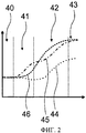
На фиг.2 представлена диаграмма процесса переключения, представленного процессом переключения на низшую передачу в одном направлении при использовании средства управления первичным валом коробки передач;Figure 2 presents a diagram of the shift process represented by the process of shifting to a lower gear in one direction using the gearbox input shaft control means;
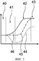
На фиг.3 представлена диаграмма процесса переключения, представленного процессом переключения на низшую передачу в одном направлении при использовании средства управления промежуточным валом коробки передач;FIG. 3 is a diagram of a shift process represented by a downshift process in one direction using gearbox intermediate shaft control means;
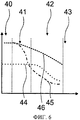
На фиг.4 представлена диаграмма процесса переключения, представленного процессом переключения на низшую передачу в противоположном направлении при использовании средства управления промежуточным валом коробки передач;4 is a diagram of a shift process represented by a downshift process in the opposite direction when using gearbox intermediate shaft control;
На фиг.5 представлена диаграмма процесса переключения, представленного процессом переключения на низшую передачу в противоположном направлении при использовании средства управления первичным валом коробки передач;5 is a diagram of a shift process represented by a downshift process in the opposite direction when using gearbox primary shaft control;
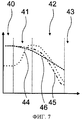
На фиг.6 представлена диаграмма процесса переключения, представленного процессом переключения на высшую передачу в одном направлении при использовании средства управления первичным валом коробки передач;6 is a diagram of a shifting process represented by a shifting process to a higher gear in one direction using gearbox input shaft control means;
На фиг.7 представлена диаграмма процесса переключения, представленного процессом переключения на высшую передачу в одном направлении при использовании средства управления промежуточным валом коробки передач;7 is a diagram of a shifting process represented by a shifting process to a higher gear in one direction using gearbox intermediate shaft control means;
На фиг.8 представлена диаграмма процесса переключения, представленного процессом переключения на высшую передачу в противоположном направлении при использовании средства управления промежуточным валом коробки передач;On Fig presents a diagram of the shift process, represented by the process of shifting to a higher gear in the opposite direction when using means for controlling the intermediate shaft of the gearbox;
На фиг.9 представлена диаграмма процесса переключения, представленного процессом переключения на высшую передачу в противоположном направлении при использовании средства управления первичным валом коробки передач.FIG. 9 is a diagram of a shift process represented by a shift to a higher gear in the opposite direction when using gearbox input shaft control.
На фиг.1 представлена трансмиссия автомобиля с примером устройства групповой передачи, содержащего блок 18 основной коробки передач и блок 10 переднего делителя коробки передач. При помощи блока 18 основной коробки передач могут быть выбраны несколько основных передач. При помощи блока 10 переднего делителя коробки основные передачи, выбираемые с помощью блока 18 основной коробки передач, могут в каждом случае переключаться на повышенную поделенную передачу и пониженную поделенную передачу. Кроме того, устройство групповой передачи содержит блок 22 заднего делителя коробки передач, при помощи которого поделенные передачи, которые могут быть сформированы блоком 18 основной коробки передач и блоком 10 переднего делителя коробки передач, делятся на два диапазона передач. Кроме того, трансмиссия содержит основной двигатель 23, сконструированный как двигатель внутреннего сгорания. Основной двигатель 23 размещен в силовом потоке перед устройством групповой передачи.Figure 1 shows the transmission of an automobile with an example of a multicast device comprising a main gearbox unit 18 and a gearbox front splitter unit 10. Using the main gearbox 18, several main gears can be selected. With the help of the block 10 of the front splitter of the box, the main gears selected with the help of the block 18 of the main gearbox can in each case switch to a higher divided gear and a low divided gear. In addition, the multicast device comprises a rear gearbox divider block 22, by which divided gears, which can be formed by the main gearbox 18 and the front gearbox divider 10, are divided into two transmission ranges. In addition, the transmission contains a main engine 23, designed as an internal combustion engine. The main engine 23 is placed in the power stream in front of the multicast device.
Устройство групповой передачи дополнительно содержит сцепление 24, включаемое при трогании автомобиля с места, и первичный вал 16 коробки передач, связанный со сцеплением 24, включаемым при трогании автомобиля с места. Первичный вал 16 коробки передач расположен в силовом потоке между сцеплением 24, включаемым при трогании автомобиля с места, и блоком 10 делителя коробки передач. Далее устройство передачи дополнительно содержит промежуточный вал 25 коробки передач, который расположен в силовом потоке между блоком 18 основной коробки передач и блоком 22 заднего делителя коробки передач. Кроме того, устройство групповой передачи содержит выходной вал 26 коробки передач, который в силовом потоке расположен после блока 22 заднего делителя коробки передач.The group transmission device further comprises a clutch 24, included when starting the car from a place, and a primary shaft 16 of the gearbox associated with a clutch 24, included when starting the car from a place. The input shaft 16 of the gearbox is located in the power flow between the clutch 24, included when starting the vehicle from the place, and the block 10 of the gearbox divider. Further, the transmission device further comprises an intermediate shaft 25 of the gearbox, which is located in the power flow between the block 18 of the main gearbox and the block 22 of the rear gearbox divider. In addition, the multicast device contains an output shaft 26 of the gearbox, which is located in the power stream after the block 22 of the rear gearbox divider.
Блок 10 переднего делителя коробки передач выполнен по типу промежуточной передачи. Блок 10 переднего делителя коробки передач содержит промежуточный вал 14 коробки передач, расположенный параллельно первичному валу 16 коробки передач. Для связи первичного вала 16 коробки передач с промежуточным валом 14 блок 10 переднего делителя коробки передач содержит две плоскости шестерен 27, 28 и средство переключения 13 для выбора плоскостей шестерен 27, 28. Посредством двух плоскостей шестерен 27 и 28 можно выбирать два разных передаточных отношения для формирования поделенных передач блока 10 переднего делителя коробки передач. Средство переключения 13 блока 10 переднего делителя коробки передач выполнено в виде несинхронизированной кулачковой муфты. Таким образом, блок 10 переднего делителя коробки передач содержит только средство переключения 13 без блокирующего кольца синхронизатора.Block 10 of the front gearbox splitter is made as an intermediate gear. Block 10 of the front gearbox divider contains an intermediate shaft 14 of the gearbox located parallel to the input shaft 16 of the gearbox. To communicate the input shaft 16 of the gearbox with the intermediate shaft 14, the block 10 of the front gearbox divider contains two planes of gears 27, 28 and switching means 13 for selecting the planes of gears 27, 28. By means of two planes of gears 27 and 28, two different gear ratios can be selected for the formation of the divided gear unit 10 of the front gearbox splitter. The switching means 13 of the block 10 of the front splitter of the gearbox is made in the form of an unsynchronized cam clutch. Thus, the block 10 of the front gearbox divider contains only the switching means 13 without the locking ring of the synchronizer.
Блок 18 основной коробки передач также выполнен по типу промежуточной передачи. Промежуточный вал 14 коробки передач сконструирован как одна деталь для блока 10 переднего делителя коробки передач и для блока 18 основной коробки передач. Для связи промежуточного вала 14 коробки передач с промежуточным валом 25 коробки передач блок 18 основной коробки передач содержит четыре плоскости шестерен 29, 30, 31, 32 и три средства переключения 19, 20, 21 для выбора плоскостей шестерен 29, 30, 31, 32. С помощью плоскостей шестерен 29, 30, 31 могут быть выбраны три основных передачи, которые сформированы как передачи переднего хода. Плоскость шестерен 32 предназначена для выбора передач заднего хода. Для формирования прямой передачи промежуточный вал 25 коробки передач может быть неподвижно соединен с первичным валом 16 коробки передач посредством двух средств переключения 13, 19. Средства переключения 19, 20, 21 блока 18 основной коробки передач выполнены как несинхронизированные кулачковые муфты. Таким образом, блок 18 основной коробки передач содержит только средства переключения 19, 20, 21 без блокирующего кольца синхронизатора.Block 18 of the main gearbox is also made as an intermediate gear. The intermediate shaft 14 of the gearbox is designed as one part for the block 10 of the front gearbox divider and for block 18 of the main gearbox. To communicate the intermediate shaft 14 of the gearbox with the intermediate shaft 25 of the gearbox, the main gearbox 18 contains four gear planes 29, 30, 31, 32 and three gears 19, 20, 21 for selecting gear planes 29, 30, 31, 32. Using the planes of the gears 29, 30, 31, three main gears can be selected, which are formed as forward gears. The plane of gears 32 is designed to select reverse gears. To form a direct transmission, the intermediate shaft 25 of the gearbox can be fixedly connected to the input shaft 16 of the gearbox by means of two shifting means 13, 19. The shifting means 19, 20, 21 of the block 18 of the main gearbox are designed as non-synchronized cam clutches. Thus, the block 18 of the main gearbox contains only the switching means 19, 20, 21 without the locking ring of the synchronizer.
Блок 22 заднего делителя коробки передач выполнен в виде планетарного механизма. Он содержит солнечную шестерню 33, которая может быть неподвижно соединена с промежуточным валом 25 коробки передач. Кроме того, он содержит водило планетарной передачи 34, которое неподвижно соединено с выходным валом 26 коробки передач, и коронную шестерню 35. Для выбора диапазонов передач блок 22 заднего делителя коробки передач снабжен средством переключения 37, посредством которого коронная шестерня 35 может быть соединена с корпусом 36 коробки передач или с солнечной шестерней 33. Средство переключения 37 выполнено в виде синхронизированной кулачковой муфты. Для синхронизации средство переключения 37 содержит два блокирующих кольца синхронизатора, при помощи которых создается фрикционная связь между переключающими элементами средства переключения 37, которые соединяются в процессе переключения.Block 22 of the rear gear divider is made in the form of a planetary mechanism. It contains a sun gear 33, which can be fixedly connected to the intermediate shaft 25 of the gearbox. In addition, it contains a planetary gear carrier 34, which is fixedly connected to the output shaft 26 of the gearbox, and a ring gear 35. To select transmission ranges, the rear gearbox divider block 22 is provided with switching means 37, by means of which the ring gear 35 can be connected to the housing 36 gearbox or with sun gear 33. The switching means 37 is made in the form of a synchronized cam clutch. For synchronization, the switching means 37 contains two locking rings of the synchronizer, by means of which a frictional connection is created between the switching elements of the switching means 37, which are connected during the switching process.
Для процессов переключения, в которых изменяется общее передаточное число устройства групповой передачи, устройство групповой передачи содержит активный исполнительный блок 11, при помощи которого в блок 18 основной коробки передач и блок 10 переднего делителя коробки может быть подан управляющий момент. Устройство групповой передачи дополнительно содержит блок управления и регулирования 12, при помощи которого управляющий момент, подаваемый в блок 18 основной коробки передач, и управляющий Момент, подаваемый в блок 10 переднего делителя коробки передач, может быть согласован с процессами переключения устройства групповой передачи, выполняемыми устройством групповой передачи, в частности, с процессами переключения, выполняемыми блоком 10 переднего делителя коробки передач.For switching processes in which the total gear ratio of the multicast device is changed, the multicast device contains an active execution unit 11, by which a control torque can be supplied to the main gearbox 18 and the front box divider 10. The multicast device further comprises a control and regulation unit 12, by means of which the control torque supplied to the main gearbox 18 and the control moment supplied to the front gearbox divider 10 can be coordinated with the multicast switching processes of the device group transmission, in particular, with the switching processes performed by the block 10 of the front gearbox splitter.
Управляющие моменты, настраиваемые с помощью исполнительного блока 11, являются плавно регулируемыми между нижним предельным значением и верхним предельным значением, по меньшей мере, в поддиапазонах. Нижнее предельное значение меньше нуля, что соответствует приему управляющих моментов. Верхнее предельное значение больше нуля, что соответствует передаче управляющих моментов. Исполнительный блок 11 является независимым от основного двигателя 23.The control moments adjustable by the actuating unit 11 are continuously adjustable between the lower limit value and the upper limit value, at least in the subranges. The lower limit value is less than zero, which corresponds to the reception of control moments. The upper limit value is greater than zero, which corresponds to the transfer of control moments. The Executive unit 11 is independent of the main engine 23.
Управляющий момент в процессах переключения, которые выполняются блоком переднего делителя коробки передач, согласовывается с соответствующим процессом переключения. В процессах переключения, которые проводятся с помощью блока 10 переднего делителя коробки передач, изменяется положение переключения средства переключения 13 блока 10 переднего делителя коробки передач. Положение переключения средств переключения 19, 20, 21 блока 18 основной коробки передач может также изменяться при таком процессе переключения. Альтернативно, положения переключения средств переключения 19, 20, 21 блока 18 основной коробки передач могут сохраняться при таком процессе переключения.The control torque in the shift processes that are performed by the gearbox front splitter unit is consistent with the corresponding shift process. In the switching processes that are carried out using the block 10 of the front gearbox divider, the switching position of the switching means 13 of the block 10 of the front gearbox divider is changed. The switching position of the switching means 19, 20, 21 of the block 18 of the main gearbox can also change with this switching process. Alternatively, the shift positions of the shifting means 19, 20, 21 of the main gearbox 18 can be maintained during such a shifting process.
Блок 10 переднего делителя коробки передач синхронизируется при помощи управляющего момента, подаваемого в блок 10 переднего делителя коробки передач посредством исполнительного блока 11. Средство переключения 13 блока переднего делителя коробки передач содержит один входной элемент связи и два выходных элемента связи. Входной элемент связи сконфигурирован в виде смещаемой по оси скользящей муфты, которая может факультативно соединяться с одним из двух выходных элементов связи, сконфигурированных в виде кулачков муфты включения.Block 10 of the front gearbox divider is synchronized using the control torque supplied to the block 10 of the front gearbox divider by means of the actuating unit 11. The switching means 13 of the front gearbox divider unit contains one input communication element and two output communication elements. The input coupling element is configured as an axially displaceable sliding coupling, which can optionally be connected to one of two output coupling elements configured as cams of the clutch.
Во время синхронизации блока 10 переднего делителя коробки передач число оборотов входного элемента связи и число оборотов выбираемого выходного элемента связи сближают друг с другом до тех пор, пока между входным элементом связи и выбираемым выходным элементом связи не установится соединение с геометрическим замыканием. Исполнительный блок 11 для этой цели активно соединяется с входным элементом связи и двумя выходными элементами связи средства переключения 13. В ходе процесса переключения блок управления и регулирования 12 согласует управляющий момент с числом оборотов 45 первичного вала 16 коробки передач и с числом оборотов 44 промежуточного вала 14 коробки передач. Число оборотов 45 первичного вала 16 коробки передач и число оборотов 44 промежуточного вала 14 коробки передач может быть определено независимо друг от друга с помощью сенсорного блока, который здесь подробно не рассмотрен. В ходе процесса переключения числа оборотов 44, 45 настраиваются посредством исполнительного блока 11 на заданное число оборотов для переключения блока 10 переднего делителя коробки передач или на заданное число оборотов для переключения блока 18 основной коробки передач. Кроме того, блок управления и регулирования 11 может предварительно задавать число оборотов 46 для основного двигателя 23. Число оборотов 46, предварительно задаваемое для основного двигателя 23, настраивается с помощью дополнительного блока управления и регулирования, не рассмотренного здесь подробно, который связан с блоком управления и регулирования 12.During synchronization of the front gearbox divider unit 10, the number of revolutions of the input communication element and the number of revolutions of the selected output communication element are brought together until a connection with a geometric circuit is established between the input communication element and the selected output communication element. The Executive unit 11 for this purpose is actively connected to the input communication element and two output communication elements of the switching means 13. During the switching process, the control and regulation unit 12 coordinates the control moment with the number of
Для настройки числа оборотов 44 промежуточного вала 14 коробки передач исполнительный блок 11 содержит средство управления 15 промежуточным валом коробки передач, с помощью которого может быть настроен управляющий момент для промежуточного вала 14 коробки передач. Средство управления 15 промежуточным валом коробки передач подает управляющий момент непосредственно на промежуточный вал коробки передач. Промежуточный вал 14 коробки передач активно соединен посредством двух плоскостей шестерен 27, 28 с выходными элементами связи. Таким образом, с помощью средства управления 15 промежуточным валом коробки передач может быть настроено число оборотов для выходных элементов связи.To adjust the number of
Для настройки числа оборотов 45 первичного вала 16 коробки передач исполнительный блок 11 содержит средство управления 17 первичным валом коробки передач, с помощью которого может быть настроен управляющий момент для первичного вала 16 коробки передач. Средство управления 17 первичным валом коробки передач подает управляющий момент на первичный вал 16 коробки передач. Первичный вал 16 коробки передач соединен со входным элементом связи. Таким образом, с помощью средства управления 17 первичным валом коробки передач может быть настроено число оборотов для выходного элемента связи.To adjust the number of
Средство управления 15 промежуточным валом коробки передач и средство управления 17 первичным валом коробки передач соответственно содержат электромоторы 38, 39, при помощи которых могут быть приняты и переданы управляющие моменты. Для приема управляющего момента электродвигатели 38, 39 в зависимости от предварительно задаваемого блоком управления и регулирования 12 режима эксплуатации либо работают как генераторы, либо приводятся в действие в противоположном направлении. Электродвигатель 38 средства управления 15 промежуточным валом коробки передач размещен соосно с промежуточным валом 14 коробки передач. Электродвигатель 39 средства управления 17 первичным валом коробки передач размещен соосно с первичным валом 16 коробки передач. Однако, в принципе допустимо также смещенное расположение, например, с использованием шестерен.The control means 15 of the intermediate shaft of the gearbox and the control means 17 of the primary shaft of the gearbox respectively comprise electric motors 38, 39, by means of which control moments can be received and transmitted. To receive the control torque, the electric motors 38, 39, depending on the operating mode preset by the control and regulation unit 12, either operate as generators or are driven in the opposite direction. The electric motor 38 of the control means 15 of the intermediate shaft of the gearbox is placed coaxially with the intermediate shaft 14 of the gearbox. The electric motor 39 of the control means 17 of the input shaft of the gearbox is aligned with the input shaft 16 of the gearbox. However, in principle, an offset arrangement is also acceptable, for example using gears.
С помощью блока управления и регулирования 12 синхронизируются, по меньшей мере, все процессы переключения средством переключения 13 блока 10 переднего делителя коробки передач. Кроме того, с помощью блока управления и регулирования 12 исключаются положения «зуб на зуб» средства переключения 13 блока 10 переднего делителя коробки передач. Дополнительно, с помощью блока управления и регулирования 12 могут быть синхронизированы процессы переключения средств переключения 19, 20, 21 блока 18 основной коробки передач. Кроме того, с помощью блока управления и регулирования 12 могут быть исключены положения «зуб на зуб» средств переключения 19, 20, 21 блока 18 основной коробки передач. Для синхронизации и исключения положений «зуб на зуб» средство управления 15 промежуточным валом коробки передач и средство управления 17 первичным валом коробки передач могут быть настроены с помощью блока управления и регулирования 12 независимо друг от друга. В зависимости от того, должен ли быть выполнен процесс переключения и/или должно ли быть исключено положение «зуб на зуб», управляющий момент подается на промежуточный вал 14 коробки передач или первичный вал 16 коробки передач.Using the control and regulation unit 12, at least all the switching processes by the switching means 13 of the block 10 of the front gearbox are synchronized. In addition, with the help of the control and regulation unit 12, the “tooth-to-tooth” positions of the switching means 13 of the block 10 of the front gearbox divider are eliminated. Additionally, using the control and regulation unit 12, the switching processes of the switching means 19, 20, 21 of the main gearbox unit 18 can be synchronized. In addition, with the help of the control and regulation unit 12, the “tooth-to-tooth” positions of the switching means 19, 20, 21 of the main gearbox unit 18 can be eliminated. To synchronize and eliminate tooth-to-tooth positions, the control means 15 of the gearbox intermediate shaft and the control means 17 of the gearbox input shaft can be set independently by the control and regulation unit 12. Depending on whether the switching process should be carried out and / or whether the tooth-to-tooth position should be excluded, the control torque is applied to the intermediate shaft 14 of the gearbox or the input shaft 16 of the gearbox.
В процессе переключения в противоположном направлении, при котором передаточное число блока 10 переднего делителя коробки передач и передаточное число блока 18 основной коробки передач изменяются в противоположных направлениях, управляющий момент подается на промежуточный вал 14 коробки передач. В процессе переключения, при котором переключение происходит только в блоке 10 переднего делителя коробки передач, управляющий момент подается на первичный вал 16 коробки передач. В процессе переключения в одном направлении, при котором передаточное число блока 10 переднего делителя коробки передач и передаточное число блока 18 основной коробки передач изменяются в одном направлении, управляющий момент подается на первичный вал 16 коробки передач. Также допустимы и альтернативные режимы эксплуатации.In the process of switching in the opposite direction, in which the gear ratio of the block 10 of the front gearbox divider and the gear ratio of the block 18 of the main gearbox are changed in opposite directions, the control torque is supplied to the intermediate shaft 14 of the gearbox. In the switching process, in which switching occurs only in the block 10 of the front gearbox divider, the control moment is supplied to the input shaft 16 of the gearbox. In the process of switching in one direction, in which the gear ratio of the block 10 of the front gearbox divider and the gear ratio of the block 18 of the main gearbox change in one direction, the control torque is applied to the input shaft 16 of the gearbox. Alternative modes of operation are also acceptable.
Процесс переключения на низшую передачу в одном направлении выполняется предпочтительно с помощью средства, управления 17 первичным валом коробки передач. В процессе переключения на низшую передачу блок 18 основной коробки передач переключается с высокой основной передачи на низкую основную передачу. Кроме того, блок 10 переднего делителя коробки передач переключается с повышенной поделенной передачи на пониженную поделенную передачу. Для начала процесса переключения блок управления и регулирования 12 сначала переключает блок 18 основной коробки передач в нейтральное положение. Кроме того, блок управления и регулирования 12 размыкает сцепление 24, включаемое при трогании автомобиля с места.The process of shifting to a lower gear in one direction is preferably performed by means of control 17 of the input shaft of the gearbox. In the process of shifting to a lower gear, the main gear unit 18 shifts from a high main gear to a low main gear. In addition, the gearbox front splitter unit 10 shifts from an increased divided gear to a low divided gear. To start the switching process, the control and regulation unit 12 first switches the main transmission unit 18 to the neutral position. In addition, the control and regulation unit 12 opens the clutch 24, which is activated when the vehicle starts.
В первой фазе 40 процесса переключения блок управления и регулирования 12 переключает блок 10 переднего делителя коробки передач с повышенной поделенной передачи в нейтральное положение. Во второй фазе 41 блок управления и регулирования 12 увеличивает с помощью средства управления 17 первичным валом коробки передач число оборотов 45 первичного вала 16 коробки передач до заданного числа оборотов для переключения блока 10 переднего делителя коробки передач. Как только первичный вал 16 коробки передач достигает заданного числа оборотов для переключения блока 10 переднего делителя коробки передач, блок управления и регулирования 12 переключает блок 10 переднего делителя коробки передач на пониженную поделенную передачу. Одновременно с увеличением числа оборотов 45 первичного вала 16 коробки передач блок управления и регулирования 12 задает увеличение числа оборотов 46 основного двигателя 23. В третьей фазе 42 блок управления и регулирования 12 замыкает сцепление 24, включаемое при трогании автомобиля с места. Число оборотов 46 основного двигателя 23 в ходе этого процесса дополнительно увеличивается до тех пор, пока не достигает заданного блоком управления и регулирования 12 числа оборотов для переключения блока 18 основной коробки передач. Вследствие замыкания сцепления 24, включаемого при трогании автомобиля с места, число оборотов 45 первичного вала 16 коробки передач увеличивается до тех пор, пока не становится равным числу оборотов 46 основного двигателя 23. Как только число оборотов 46 основного двигателя 23 достигает заданного числа оборотов для переключения блока 18 основной коробки передач, блок 18 основной коробки передач переключается на более низкую основную передачу в четвертой фазе 43, чем процесс переключения и заканчивается (см. фиг.2).In the
Процесс переключения на низшую передачу в одном направлении альтернативно может быть выполнен с помощью средства управления 15 промежуточным валом коробки передач. Для начала процесса переключения блок управления и регулирования 12 сначала переключает блок 18 основной коробки передач в нейтральное положение. Кроме того, блок управления и регулирования 12 размыкает сцепление 24, включаемое при трогании автомобиля с места.The process of shifting to a lower gear in one direction can alternatively be carried out by means of control means 15 of the intermediate shaft of the gearbox. To start the switching process, the control and regulation unit 12 first switches the main transmission unit 18 to the neutral position. In addition, the control and regulation unit 12 opens the clutch 24, which is activated when the vehicle starts.
В первой фазе 40 процесса переключения блок управления и регулирования 12 переключает блок 10 переднего делителя коробки передач с повышенной поделенной передачи в нейтральное положение. Во второй фазе 41 блок управления и регулирования 12 уменьшает с помощью средства управления 15 промежуточным валом коробки передач число оборотов 44 промежуточного вала 14 коробки передач до заданного числа оборотов для переключения блока 10 переднего делителя коробки передач. Как только промежуточный вал 14 коробки передач достигает заданного числа оборотов для переключения блока 10 переднего делителя коробки передач, блок управления и регулирования 12 переключает блок переднего делителя коробки передач на пониженную поделенную передачу. Одновременно с уменьшением числа оборотов 44 промежуточного вала 14 коробки передач блок управления и регулирования 12 задает увеличение числа оборотов 46 основного двигателя 23. В третьей фазе 42 блок управления и регулирования 12 замыкает сцепление 24, включаемое при трогании автомобиля с места. Число оборотов 46 основного двигателя 23 в ходе этого процесса дополнительно увеличивается до тех пор, пока не достигает заданного блоком управления и регулирования 12 числа оборотов для переключения блока 18 основной коробки передач. Вследствие замыкания сцепления 24, включаемого при трогании автомобиля с места, число оборотов 45 первичного вала 16 коробки передач увеличивается до тех пор, пока не становится равным числу оборотов 46 основного двигателя 23. Как только число оборотов 46 основного двигателя 23 достигает заданного числа оборотов для переключения блока 18 основной коробки передач, блок 18 основной коробки передач переключается на более низкую основную передачу в четвертой фазе 43, чем процесс переключения и заканчивается (см. фиг.3).In the
Процесс переключения на низшую передачу в противоположном направлении выполняется предпочтительно с помощью средства управления 15 промежуточным валом коробки передач. В процессе переключения на низшую передачу блок 18 основной коробки передач переключается с высокой основной передачи на низкую основную передачу. Кроме того, блок 10 переднего делителя коробки передач переключается с пониженной поделенной передачи на повышенную поделенную передачу. Для начала процесса переключения блок управления и регулирования 12 сначала переключает блок 18 основной коробки передач в нейтральное положение. Кроме того, блок управления и регулирования 12 размыкает сцепление 24, включаемое при трогании автомобиля с места.The downshift process in the opposite direction is preferably performed by means of control means 15 of the transmission intermediate shaft. In the process of shifting to a lower gear, the main gear unit 18 shifts from a high main gear to a low main gear. In addition, the gearbox front splitter unit 10 shifts from a low divided gear to a high divided gear. To start the switching process, the control and regulation unit 12 first switches the main transmission unit 18 to the neutral position. In addition, the control and regulation unit 12 opens the clutch 24, which is activated when the vehicle starts.
В первой фазе 40 процесса переключения блок управления и регулирования 12 переключает блок 10 переднего делителя коробки передач с пониженной поделенной передачи в нейтральное положение. Во второй фазе 41 блок управления и регулирования 12 увеличивает с помощью средства управления 15 Промежуточным валом коробки передач число оборотов 44 промежуточного вала 14 коробки передач до заданного числа оборотов для переключения блока 10 переднего делителя коробки передач. Как только промежуточный вал 14 коробки передач достигает заданного числа оборотов для переключения блока 10 переднего делителя коробки передач, блок управления и регулирования 12 переключает блок 10 переднего делителя коробки передач на повышенную поделенную передачу. Одновременно с увеличением числа оборотов 44 промежуточного вала 14 коробки передач блок управления и регулирования 12 задает увеличение числа оборотов 46 основного двигателя 23. В третьей фазе 42 блок управления и регулирования 12 замыкает сцепление 24, включаемое при трогании автомобиля с места. Число оборотов 46 основного двигателя 23 в ходе этого процесса дополнительно увеличивается, пока не достигает заданного блоком управления и регулирования 12 числа оборотов для переключения блока 18 основной коробки передач. Вследствие замыкания сцепления 24, включаемого при трогании автомобиля с места, число оборотов 45 первичного вала 16 коробки передач увеличивается до тех пор, пока не становится равным числу оборотов 46 основного двигателя 23. Как только число оборотов 46 основного двигателя 23 достигает заданного числа оборотов для переключения блока 18 основной коробки передач, блок 18 основной коробки передач переключается на более низкую основную передачу в четвертой фазе 43, чем процесс переключения и заканчивается (см. фиг.4).In the
Процесс переключения на низшую передачу в противоположном направлении альтернативно может быть выполнен с помощью средства управления 17 первичным валом коробки передач. Для начала процесса переключения блок управления и регулирования 12 сначала переключает блок 18 основной коробки передач в нейтральное положение. Кроме того, блок управления и регулирования 12 размыкает сцепление 24, включаемое при трогании автомобиля с места.The process of shifting to a lower gear in the opposite direction can alternatively be carried out by means of control means 17 of the gearbox input shaft. To start the switching process, the control and regulation unit 12 first switches the main transmission unit 18 to the neutral position. In addition, the control and regulation unit 12 opens the clutch 24, which is activated when the vehicle starts.
В первой фазе 40 процесса переключения блок управления и регулирования 12 переключает блок 10 переднего делителя коробки передач с пониженной поделенной передачи в нейтральное положение. Во второй фазе 41 блок управления и регулирования 12 уменьшает с помощью средства управления 17 первичным валом коробки передач число оборотов 45 первичного вала 16 коробки передач до заданного числа оборотов для переключения блока 10 переднего делителя коробки передач. Как только первичный вал 16 коробки передач достигает заданного числа оборотов для переключения блока 10 переднего делителя коробки передач, блок управления и регулирования 12 переключает блок 10 переднего делителя коробки передач на пониженную поделенную передачу. Одновременно с уменьшением числа оборотов 45 первичного вала 16 коробки передач блок управления и регулирования 12 задает увеличение числа оборотов 46 основного двигателя 23. В третьей фазе 42 блок управления и регулирования 12 замыкает сцепление 24, включаемое при трогании автомобиля с места. Число оборотов 46 основного двигателя 23 в ходе этого процесса дополнительно увеличивается до тех пор, пока не достигает заданного блоком управления и регулирования 12 числа оборотов для включения блока 18 основной коробки передач. Вследствие замыкания сцепления 24, включаемого при трогании автомобиля с места, число оборотов 45 первичного вала 16 коробки передач увеличивается до тех пор, пока не становится равным числу оборотов 46 основного двигателя 23. Как только число оборотов 46 основного двигателя 23 достигает заданного числа оборотов для переключения блока 18 основной коробки передач, блок 18 основной коробки передач переключается на более низкую основную передачу в четвертой фазе 43, чем процесс переключения и заканчивается (см. фиг.5).In the
В альтернативном режиме эксплуатации блок управления и регулирования 12 в процессах переключения на низшую передачу в третьей фазе 42 не производит замыкания сцепления 24, включаемого при трогании автомобиля с места. Вместо этого в третьей фазе 42 число оборотов 45 первичного вала 16 коробки передач с помощью средства управления 17 первичным валом коробки передач и/или с помощью средства управления 15 промежуточным валом коробки передач настраивается на заданное число оборотов для переключения блока 18 основной коробки передач. Как только число оборотов 45 первичного вала 16 коробки передач достигает заданного числа оборотов для переключения блока 18 основной коробки передач, блок 18 основной коробки передач переключается на более низкую основную передачу в четвертой фазе 43. Затем сцепление 24, включаемое при трогании автомобиля с места, замыкается, чем процесс переключения на низшую передачу и завершается.In an alternative mode of operation, the control and regulation unit 12 in the processes of shifting to a lower gear in the
Процесс переключения на высшую передачу в одном направлении выполняется предпочтительно с помощью средства управления 17 первичным валом коробки передач. В процессе переключения на высшую передачу блок 18 основной коробки передач переключается с низкой основой передачи на высокую основную передачу. Кроме того, узел блока 10 переднего делителя коробки передач переключается с пониженной поделенной передачи на повышенную поделенную передачу. Для начала процесса переключения блок управления и регулирования 12 сначала переключает блок 18 основной коробки передач в нейтральное положение. Кроме того, блок управления и регулирования 12 размыкает сцепление 24, включаемое при трогании автомобиля с места.The process of shifting to a higher gear in one direction is preferably carried out by means of control means 17 of the input shaft of the gearbox. In the process of shifting to a higher gear, the main gearbox 18 shifts from a low gear base to a high main gear. In addition, the unit of the block 10 of the front splitter of the gearbox is switched from a low divided gear to a high divided gear. To start the switching process, the control and regulation unit 12 first switches the main transmission unit 18 to the neutral position. In addition, the control and regulation unit 12 opens the clutch 24, which is activated when the vehicle starts.
В первой фазе 40 процесса переключения блок управления и регулирования 12 переключает блок 10 переднего делителя коробки передач с пониженной поделенной передачи в нейтральное положение. Во второй фазе 41 блок управления и регулирования 12 с помощью средства управления 17 первичным валом коробки передач уменьшает число оборотов 45 первичного вала 16 до заданного числа оборотов для включения блока 10 переднего делителя коробки передач. Задаваемое для числа оборотов 45 значение меньше числа оборотов 44, которое характеризует вращение промежуточного вала 14 коробки передач во второй фазе 41. Как только первичный вал 16 коробки передач достигает заданного числа оборотов для переключения блока 10 переднего делителя коробки передач, блок управления и регулирования 12 переключает блок 10 переднего делителя коробки передач на повышенную поделенную передачу. Одновременно с уменьшением числа оборотов 45 первичного вала 16 коробки передач блок управления и регулирования 12 задает уменьшение числа оборотов 46 основного двигателя 23. В третьей фазе 42 блок управления и регулирования 12 дополнительно уменьшает с помощью средства управления 17 первичным валом число оборотов 45 первичного вала 16 коробки передач. Одновременно с дополнительным уменьшением числа оборотов 45 первичного вала 16 коробки передач дополнительно уменьшается число оборотов 46 основного двигателя 23. Как только число оборотов 45 первичного вала 16 коробки передач достигает заданного числа оборотов для переключения блока 18 основной коробки передач, блок 18 основной коробки передач переключается на более высокую основную передачу в четвертой фазе 43. Затем сцепление 24, включаемое при трогании автомобиля с места, замыкается, чем процесс переключения и завершается (см. фиг.6).In the
Процесс переключения на высшую передачу в одном направлении альтернативно может быть выполнен с помощью средства управления 15 промежуточным валом коробки передач. Для начала процесса переключения блок управления и регулирования 12 сначала переключает блок 18 основной коробки передач в нейтральное положение. Кроме того, блок управления и регулирования 12 размыкает сцепление 24, включаемое при трогании автомобиля с места.The process of shifting to a higher gear in one direction can alternatively be carried out by means of control means 15 of the intermediate shaft of the gearbox. To start the switching process, the control and regulation unit 12 first switches the main transmission unit 18 to the neutral position. In addition, the control and regulation unit 12 opens the clutch 24, which is activated when the vehicle starts.
В первой фазе 40 процесса переключения блок управления и регулирования 12 переключает блок 10 переднего делителя коробки передач с пониженной поделенной передачи в нейтральное положение. Во второй фазе 41 блок управления и регулирования 12 увеличивает с помощью средства управления 15 промежуточным валом коробки передач число оборотов 44 промежуточного вала 14 коробки передач до заданного числа оборотов для переключения блока 10 переднего делителя коробки передач. Как только промежуточный вал 14 коробки передач достигает заданного числа оборотов для переключения блока 10 переднего делителя коробки передач, блок управления и регулирования 12 переключает блок 10 переднего делителя коробки передач на повышенную поделенную передачу. Одновременно с увеличением числа оборотов 44 промежуточного вала 14 коробки передач блок управления и регулирования 12 задает уменьшение числа оборотов 46 основного двигателя 23. В третьей фазе 42 блок управления и регулирования 12 уменьшает число оборотов 44 промежуточного вала 14 коробки передач с помощью средства управления 15 промежуточным валом коробки передач. Одновременно с уменьшением числа оборотов 44 промежуточного вала 14 дополнительно уменьшается число оборотов 46 основного двигателя 23. Как только число оборотов 44 промежуточного вала 14 коробки передач достигает заданного числа оборотов для переключения блока 18 основной коробки передач, блок 18 основной коробки передач переключается на более высокую основную передачу в четвертой фазе 43. Затем сцепление 24, включаемое при трогании автомобиля с места, замыкается, чем процесс переключения и завершается (см. фиг.7).In the
Процесс переключения на высшую передачу в противоположном направлении выполняется предпочтительно с помощью средства управления 15 промежуточным валом коробки передач. В процессе переключения на высшую передачу блок 18 основной коробки передач переключается с низкой основной передачи на высокую основную передачу. Кроме того, блок 10 переднего делителя коробки передач переключается с повышенной поделенной передачи на пониженную поделенную передачу. Для начала процесса переключения блок управления и регулирования 12 сначала переключает блок 18 основной коробки передач в нейтральное положение. Кроме того, блок управления и регулирования 12 размыкает сцепление 24, включаемое при трогании автомобиля с места.The process of shifting to a higher gear in the opposite direction is preferably carried out by means of control means 15 of the transmission intermediate shaft. In the process of shifting to a higher gear, the main gearbox 18 shifts from a low main gear to a high main gear. In addition, the gearbox front splitter unit 10 shifts from an increased divided gear to a low divided gear. To start the switching process, the control and regulation unit 12 first switches the main transmission unit 18 to the neutral position. In addition, the control and regulation unit 12 opens the clutch 24, which is activated when the vehicle starts.
В первой фазе 40 процесса переключения блок управления и регулирования 12 переключает блок 10 переднего делителя коробки передач с повышенной поделенной передачи в нейтральное положение. Во второй фазе 41 блок управления и регулирования 12 уменьшает с помощью средства управления 15 промежуточным валом коробки передач число оборотов 44 промежуточного вала 14 коробки передач до заданного числа оборотов для переключения блока 10 переднего делителя коробки передач. Как только промежуточный вал 14 коробки передач достигает заданного числа оборотов для переключения блока 10 переднего делителя коробки передач, блок управления и регулирования 12 переключает блок 10 переднего делителя коробки передач на пониженную поделенную передачу. Одновременно с уменьшением числа оборотов 44 промежуточного вала 14 коробки передач блок управления и регулирования 12 задает уменьшение числа оборотов 46 основного двигателя 23. В третьей фазе 42 блок управления и регулирования 12 дополнительно уменьшает с помощью средства управления 15 промежуточным валом коробки передач число оборотов 44 промежуточного вала 14 коробки передач. Одновременно с уменьшением числа оборотов 44 промежуточного вала 14 коробки передач дополнительно уменьшается число оборотов 46 основного двигателя 23. Как только число оборотов 44 промежуточного вала 14 коробки передач достигает заданного числа оборотов для переключения блока 18 основной коробки передач, блок 18 основной коробки передач переключается на более высокую основную передачу в четвертой фазе 43. Затем сцепление 24, включаемое при трогании автомобиля с места, замыкается, чем процесс переключения и завершается (см. фиг.8).In the
Процесс переключения на высшую передачу в противоположном направлении может быть альтернативно выполнен с помощью средства управления 17 первичным валом коробки передач. Для начала процесса переключения блок управления и регулирования 12 сначала переключает блока 18 основной коробки передач в нейтральное положение. Кроме того, блок управления и регулирования 12 размыкает сцепление 24, включаемое при трогании автомобиля с места.The process of shifting to a higher gear in the opposite direction can alternatively be carried out by means of control means 17 of the input shaft of the gearbox. To start the switching process, the control and regulation unit 12 first switches the main transmission unit 18 to the neutral position. In addition, the control and regulation unit 12 opens the clutch 24, which is activated when the vehicle starts.
В первой фазе 40 процесса переключения блок управления и регулирования 12 переключает блок 10 переднего делителя коробки передач с повышенной поделенной передачи в нейтральное положение. Во второй фазе 41 блок управления и регулирования 12 увеличивает с помощью средства управления 17 первичным валом коробки передач число оборотов 45 первичного вала 16 коробки передач до заданного числа оборотов для переключения блока 10 переднего делителя коробки передач. Как только первичный вал 16 коробки передач достигает заданного числа оборотов для переключения блока 10 переднего делителя коробки передач, блок управления и регулирования 12 переключает блок 10 переднего делителя коробки передач на пониженную поделенную передачу. Одновременно с увеличением числа оборотов 45 первичного вала 16 коробки передач блок управления и регулирования 12 задает уменьшение числа оборотов 46 основного двигателя 23. В третьей фазе 42 блок управления и регулирования 12 уменьшает число оборотов 45 первичного вала 16 коробки передач с помощью средства управления 17 первичным валом коробки передач. Одновременно с уменьшением числа оборотов 45 первичного вала 16 коробки передач дополнительно уменьшается число оборотов 46 основного двигателя 23. Как только число оборотов 46 первичного вала 16 коробки передач достигает заданного числа оборотов для переключения блока 18 основной коробки передач, блок 18 основной коробки передач переключается на более высокую основную передачу в четвертой фазе 43. Затем сцепление 24, включаемое при трогании автомобиля с места, замыкается, чем процесс переключения и завершается (см. фиг.9).In the
Процесс переключения, касающийся только блока 10 переднего делителя коробки передач, выполняется средством управления 17 первичным валом коробки передач. В ходе этого процесса переключения блок 10 переднего делителя коробки передач изменяет поделенную передачу в то время, как основная передача блока 18 основной коробки передач сохраняется. Для начала процесса переключения блок управления и регулирования 12 размыкает сцепление 24, включаемое при трогании автомобиля с места. Передача основной коробки передач в ходе процесса переключения остается постоянной.The switching process, relating only to the block 10 of the front gearbox splitter, is performed by the control means 17 of the input shaft of the gearbox. During this shift process, the front gearbox divider 10 changes the divided gear while the main gear of the main gearbox 18 is maintained. To start the switching process, the control and regulation unit 12 opens the clutch 24, which is engaged when starting the car from a place. The transmission of the main gearbox during the shift process remains constant.
В первой фазе процесса переключения блок управления и регулирования 12 переключает блок 10 переднего делителя коробки передач с включенной поделенной передачи в нейтральное положение. Во второй фазе блок управления и регулирования 12 изменяет с помощью средства управления 17 первичным валом коробки передач число оборотов 45 первичного вала 16 до заданного числа оборотов для включения блока 10 переднего делителя коробки передач. Как только промежуточный вал 14 коробки передач достигает заданного числа оборотов для переключения блока 10 переднего делителя коробки передач, блок управления и регулирования 12 переключает блок 10 переднего делителя коробки передач на поделенную передачу, которую необходимо включить. В третьей фазе сцепление 24, включаемое при трогании автомобиля с места, замыкается, чем процесс переключения и завершается.In the first phase of the shift process, the control and regulation unit 12 switches the block 10 of the front gearbox divider from the engaged divided gear to the neutral position. In the second phase, the control and regulation unit 12 changes the number of
Чтобы исключить в основной коробке передач 18 положение «зуб на зуб», сцепление 24, включаемое при трогании автомобиля с места, размыкается. После чего, положение «зуб на зуб» исключается с помощью средства управления 15 промежуточным валом коробки передач. При включенной поделенной передаче положение «зуб на зуб» может быть исключено дополнительно или альтернативно посредством средства управления 17 первичным валом коробки передач.To exclude the tooth-to-tooth position in the main gearbox 18, the clutch 24, which is engaged when starting the vehicle from its place, opens. After that, the tooth-to-tooth position is excluded by means of the control means 15 of the transmission intermediate shaft. When the shared gear is engaged, the tooth-to-tooth position can be eliminated additionally or alternatively by means of control means 17 of the gearbox input shaft.
В процессах переключения, касающихся только блока 18 основной коробки передач, средства переключения 19, 20, 21 блока 18 основной коробки передач синхронизируются также с помощью исполнительного блока 11. При разомкнутом сцеплении 24, включаемом при трогании автомобиля с места, блок 18 основной коробки передач синхронизируется с помощью средства управления 15 промежуточным валом коробки передач. При включенной поделенной передаче блок 18 основной коробки передач может быть синхронизирован дополнительно или альтернативно посредством средства управления 17 первичным валом коробки передач.In the switching processes, which concern only the main gearbox block 18, the switching means 19, 20, 21 of the main gearbox block 18 are also synchronized with the help of the actuating unit 11. With the clutch 24 open, which is switched on when the vehicle starts moving, the main gearbox block 18 is synchronized using control means 15 of the intermediate shaft of the gearbox. When the shared gear is engaged, the main gearbox unit 18 can be synchronized additionally or alternatively by means of the gearbox control means 17.
В режиме эксплуатации, при котором трансмиссия замкнута с силовым замыканием, исполнительный блок 11 разработан как модуль комбинированного привода, с помощью которого может быть создан дополнительный движущий момент. В этом режиме эксплуатации, при котором включены блок 10 переднего делителя коробки передач, блок 18 основной коробки передач и блок 22 заднего делителя коробки передач, управляющий момент, который формируется с помощью исполнительного блока 11, действует вместе с движущим моментом основного двигателя 23. При помощи исполнительного блока 11, сконструированного для этого режима эксплуатации в виде модуля комбинированного привода, становятся доступны режим форсирования и/или режим рекуперации. Кроме того, с помощью исполнительного блока 11, например, посредством переключения блока 18 основной коробки передач в нейтральное положение и замыкания сцепления 24, включаемого при трогании автомобиля с места, может быть предусмотрен модуль комбинированного привода, который сконструирован в виде модуля стартер-генератор.In the operating mode, in which the transmission is closed with a power circuit, the actuating unit 11 is designed as a combined drive module, with which an additional driving torque can be created. In this operating mode, in which the front gearbox divider unit 10, the main gearbox unit 18 and the rear gearbox divider unit 22 are turned on, the control moment that is generated by the actuator unit 11 acts together with the driving moment of the main engine 23. Using the executive unit 11, designed for this operating mode in the form of a combined drive module, the boost mode and / or recovery mode become available. In addition, with the help of the actuating unit 11, for example, by switching the main gearbox unit 18 to the neutral position and closing the clutch 24, which is switched on when starting the vehicle, a combined drive module can be provided, which is designed as a starter-generator module.
Claims (13)
Applications Claiming Priority (3)
| Application Number | Priority Date | Filing Date | Title |
|---|---|---|---|
| DE102009012223A DE102009012223A1 (en) | 2009-03-07 | 2009-03-07 | Group transmission device |
| DE102009012223.0 | 2009-03-07 | ||
| PCT/EP2010/001006 WO2010102711A1 (en) | 2009-03-07 | 2010-02-18 | Auxiliary-range transmission device |
Publications (2)
| Publication Number | Publication Date |
|---|---|
| RU2011140406A RU2011140406A (en) | 2013-04-20 |
| RU2489623C2 true RU2489623C2 (en) | 2013-08-10 |
Family
ID=42078808
Family Applications (1)
| Application Number | Title | Priority Date | Filing Date |
|---|---|---|---|
| RU2011140406/11A RU2489623C2 (en) | 2009-03-07 | 2010-02-18 | Group transmission device |
Country Status (7)
| Country | Link |
|---|---|
| US (1) | US8647232B2 (en) |
| EP (1) | EP2404080B1 (en) |
| JP (1) | JP5212672B2 (en) |
| CN (1) | CN102341621B (en) |
| DE (1) | DE102009012223A1 (en) |
| RU (1) | RU2489623C2 (en) |
| WO (1) | WO2010102711A1 (en) |
Cited By (1)
| Publication number | Priority date | Publication date | Assignee | Title |
|---|---|---|---|---|
| RU2680553C2 (en) * | 2014-03-06 | 2019-02-22 | Ман Трак Унд Бас Аг | Multi-group transmission, preferably double-clutch transmission |
Families Citing this family (22)
| Publication number | Priority date | Publication date | Assignee | Title |
|---|---|---|---|---|
| DE102009054752A1 (en) * | 2009-12-16 | 2011-06-22 | ZF Friedrichshafen AG, 88046 | Powertrain with an automated group transmission |
| DE102010063580A1 (en) * | 2010-12-20 | 2012-06-21 | Zf Friedrichshafen Ag | Group transmission, powertrain with group transmission and method of operating the same |
| DE102011002472A1 (en) * | 2011-01-05 | 2012-07-05 | Zf Friedrichshafen Ag | Automated manual transmission with hybrid drive |
| JP2013024391A (en) * | 2011-07-25 | 2013-02-04 | Aichi Machine Industry Co Ltd | Transmission device, and electric vehicle equipped with the same |
| DE102011080069A1 (en) * | 2011-07-29 | 2013-01-31 | Zf Friedrichshafen Ag | Automated group transmission of a motor vehicle and method for operating the same |
| DE102012005676A1 (en) * | 2012-03-21 | 2013-09-26 | Daimler Ag | Automotive powertrain device with a multi-group transmission |
| DE102012005678A1 (en) * | 2012-03-21 | 2013-09-26 | Daimler Ag | Automotive powertrain device having an active synchronizer unit |
| DE102012005675A1 (en) * | 2012-03-21 | 2013-09-26 | Daimler Ag | Automotive powertrain device with a multi-group transmission |
| DE102012218367A1 (en) * | 2012-10-09 | 2014-04-24 | Zf Friedrichshafen Ag | Group gear device with an electric machine |
| DE102013003345A1 (en) * | 2013-02-27 | 2014-08-28 | Daimler Ag | Method for releasing a tooth-on-tooth position and / or jamming in a rear-mounted group of a group transmission of a commercial vehicle |
| SE538355C2 (en) * | 2013-11-21 | 2016-05-24 | Scania Cv Ab | Method of steering a hybrid drivetrain in a vehicle so that gaps are eliminated by an electric machine |
| DE102013226709A1 (en) * | 2013-12-19 | 2015-06-25 | Zf Friedrichshafen Ag | Group transmission for a motor vehicle |
| SE1450970A1 (en) * | 2014-08-21 | 2016-02-22 | Scania Cv Ab | Transmission for vehicles, vehicles comprising such a transmission and method for controlling a transmission |
| DE102015014147B4 (en) | 2014-11-05 | 2023-07-06 | Scania Cv Ab | Method of shifting in a transmission, a gearbox and a vehicle |
| DE102015014146B4 (en) | 2014-11-05 | 2022-01-27 | Scania Cv Ab | Method of shifting in a transmission, a gearbox and a vehicle |
| KR101637753B1 (en) * | 2014-12-01 | 2016-07-07 | 현대자동차주식회사 | The shift control method of a hybrid vehicle for preventing coupling failure the starting gear stage |
| SE539370C2 (en) | 2015-04-29 | 2017-08-15 | Scania Cv Ab | A brake arrangement for an upshift process in a gearbox |
| DE102015210327B4 (en) * | 2015-06-03 | 2020-11-26 | Zf Friedrichshafen Ag | Multi-step transmission with input and output constant |
| AT520019B1 (en) * | 2017-05-08 | 2019-05-15 | Avl Commercial Driveline & Tractor Eng Gmbh | Method for operating a drive train of a motor vehicle |
| DE102017222436A1 (en) * | 2017-12-12 | 2019-06-13 | Zf Friedrichshafen Ag | Method for operating a drive train of a motor vehicle |
| JP7229976B2 (en) * | 2020-09-14 | 2023-02-28 | ヤマハ発動機株式会社 | Mobile harvesting equipment and harvesting units |
| WO2023196562A1 (en) * | 2022-04-08 | 2023-10-12 | Eaton Cummins Automated Transmission Technologies | Gear shift actuation simplification |
Citations (4)
| Publication number | Priority date | Publication date | Assignee | Title |
|---|---|---|---|---|
| RU2015039C1 (en) * | 1991-09-17 | 1994-06-30 | Александр Иванович Рябков | Method for gearshift in an automatic variable-speed gear box |
| EP1127731A2 (en) * | 2000-02-22 | 2001-08-29 | Hitachi, Ltd. | Gear shift control device and control method for a vehicle |
| WO2007031191A1 (en) * | 2005-09-14 | 2007-03-22 | Daimler Ag | Shifting claw transmission and shifting method therefor |
| DE102007018967A1 (en) * | 2007-04-21 | 2008-10-23 | Zf Friedrichshafen Ag | Automated auxiliary transmission for commercial motor vehicle, has countershafts staying in connection with hydraulic arrangement to provide auxiliary output, and drive units controlling and regulating each countershaft |
Family Cites Families (12)
| Publication number | Priority date | Publication date | Assignee | Title |
|---|---|---|---|---|
| US4375172A (en) * | 1978-10-02 | 1983-03-01 | Eaton Corporation | Blocked change gear transmission utilizing resilient shifting mechanisms and improved jaw clutch assembly therefor |
| DE60032701T2 (en) * | 1999-10-12 | 2007-11-08 | Eaton Corp., Cleveland | Approach control for a servo-assisted, manually operated splitter compound transmission |
| DE19960621B4 (en) * | 1999-12-16 | 2006-12-21 | Daimlerchrysler Ag | Hybrid drive for vehicles |
| SE516707C2 (en) | 2000-05-30 | 2002-02-19 | Volvo Lastvagnar Ab | Power units for motor vehicles |
| DE10052231A1 (en) * | 2000-10-21 | 2002-05-02 | Daimler Chrysler Ag | vehicle |
| DE10203514A1 (en) * | 2002-01-30 | 2003-08-07 | Bosch Gmbh Robert | Intermediate gear change box for transferring torque in an internal combustion engine to a motor vehicle has a layshaft under load and an auxiliary layshaft linked to a gearbox feed shaft |
| US7125362B2 (en) * | 2004-01-23 | 2006-10-24 | Eaton Corporation | Hybrid powertrain system including smooth shifting automated transmission |
| JP4602026B2 (en) * | 2004-08-10 | 2010-12-22 | 本田技研工業株式会社 | Engine equipped with an automatic transmission for vehicles |
| DE102005035328B4 (en) * | 2005-07-28 | 2015-04-09 | Zf Friedrichshafen Ag | Dual-clutch transmission with integrated electric machine and its application |
| US7640818B2 (en) * | 2007-02-23 | 2010-01-05 | Gm Global Technology Operations, Inc. | Multi-speed transmission with a countershaft gearing |
| JP5004289B2 (en) * | 2007-08-02 | 2012-08-22 | 三菱ふそうトラック・バス株式会社 | Drive device for hybrid electric vehicle |
| DE102009054752A1 (en) * | 2009-12-16 | 2011-06-22 | ZF Friedrichshafen AG, 88046 | Powertrain with an automated group transmission |
-
2009
- 2009-03-07 DE DE102009012223A patent/DE102009012223A1/en not_active Withdrawn
-
2010
- 2010-02-18 CN CN201080010920.1A patent/CN102341621B/en not_active Expired - Fee Related
- 2010-02-18 JP JP2011552341A patent/JP5212672B2/en not_active Expired - Fee Related
- 2010-02-18 WO PCT/EP2010/001006 patent/WO2010102711A1/en active Application Filing
- 2010-02-18 EP EP10705299.5A patent/EP2404080B1/en active Active
- 2010-02-18 RU RU2011140406/11A patent/RU2489623C2/en not_active IP Right Cessation
-
2011
- 2011-09-06 US US13/199,661 patent/US8647232B2/en active Active
Patent Citations (4)
| Publication number | Priority date | Publication date | Assignee | Title |
|---|---|---|---|---|
| RU2015039C1 (en) * | 1991-09-17 | 1994-06-30 | Александр Иванович Рябков | Method for gearshift in an automatic variable-speed gear box |
| EP1127731A2 (en) * | 2000-02-22 | 2001-08-29 | Hitachi, Ltd. | Gear shift control device and control method for a vehicle |
| WO2007031191A1 (en) * | 2005-09-14 | 2007-03-22 | Daimler Ag | Shifting claw transmission and shifting method therefor |
| DE102007018967A1 (en) * | 2007-04-21 | 2008-10-23 | Zf Friedrichshafen Ag | Automated auxiliary transmission for commercial motor vehicle, has countershafts staying in connection with hydraulic arrangement to provide auxiliary output, and drive units controlling and regulating each countershaft |
Cited By (1)
| Publication number | Priority date | Publication date | Assignee | Title |
|---|---|---|---|---|
| RU2680553C2 (en) * | 2014-03-06 | 2019-02-22 | Ман Трак Унд Бас Аг | Multi-group transmission, preferably double-clutch transmission |
Also Published As
| Publication number | Publication date |
|---|---|
| EP2404080A1 (en) | 2012-01-11 |
| JP5212672B2 (en) | 2013-06-19 |
| JP2012519807A (en) | 2012-08-30 |
| DE102009012223A1 (en) | 2010-09-09 |
| US8647232B2 (en) | 2014-02-11 |
| CN102341621B (en) | 2014-12-24 |
| CN102341621A (en) | 2012-02-01 |
| RU2011140406A (en) | 2013-04-20 |
| US20120031230A1 (en) | 2012-02-09 |
| EP2404080B1 (en) | 2014-05-14 |
| WO2010102711A1 (en) | 2010-09-16 |
Similar Documents
| Publication | Publication Date | Title |
|---|---|---|
| RU2489623C2 (en) | Group transmission device | |
| US8535188B2 (en) | Hybrid drive train for a motor vehicle | |
| CN109707817A (en) | Power transmitting apparatus for vehicle | |
| CN106715175B (en) | Hybrid powertrain and method for controlling the same | |
| RU2585501C2 (en) | Actuator for hybrid vehicle | |
| EP2721320B1 (en) | Power-split transmission | |
| US6811508B2 (en) | Hybrid transmission, particularly for motor vehicles | |
| EP2721323B1 (en) | Continuously variable power-split vehicle transmission | |
| KR101114390B1 (en) | A dual clutch transmission for hybrid electric vehicle | |
| JP4205878B2 (en) | Power transmission device for hybrid vehicle and control method thereof | |
| US20080227592A1 (en) | Method for Starting an Internal Combustion Engine in a Parallel Hybrid Drive Train | |
| CN105745105A (en) | Automatic transmission | |
| US10604000B2 (en) | Drive arrangement for a hybrid vehicle and power train having such a drive arrangement | |
| EP2979911B1 (en) | Hybrid powertrain unit for motor vehicles with a variable transmission device between electric machine and differential | |
| KR20190141493A (en) | Power transmission apparatus for vehicle | |
| CN109094351A (en) | Hybrid power system and hybrid vehicle | |
| US9381906B2 (en) | Vehicle driving device | |
| CN108290488B (en) | Transmission for motor vehicle and power assembly with transmission | |
| JP2016138655A (en) | Operation and controlling method of vehicle provided with automatic/manual transmission at gear change and starting stage, and vehicular gear change and starting device provided with automatic/manual transmission | |
| US9291243B2 (en) | Powershift transmission for a motor vehicle and method for controlling a powershift transmission | |
| KR20160061158A (en) | Powertrain for hybrid vehicle | |
| US9109675B2 (en) | Hybrid power train for vehicle | |
| JP2016164064A (en) | Operation and control method in gear-change stage for vehicle equipped with manual or automatic/manual transmission and vehicular transmission device equipped with manual transmission or automatic/manual transmission | |
| KR20130104387A (en) | Automated manual transmission | |
| KR101807151B1 (en) | Power transmission system of hybrid electric vehicle |
Legal Events
| Date | Code | Title | Description |
|---|---|---|---|
| MM4A | The patent is invalid due to non-payment of fees |
Effective date: 20160219 |