RU2487440C2 - Battery pack and substrate with interconnection layer - Google Patents
Battery pack and substrate with interconnection layer Download PDFInfo
- Publication number
- RU2487440C2 RU2487440C2 RU2008112062/07A RU2008112062A RU2487440C2 RU 2487440 C2 RU2487440 C2 RU 2487440C2 RU 2008112062/07 A RU2008112062/07 A RU 2008112062/07A RU 2008112062 A RU2008112062 A RU 2008112062A RU 2487440 C2 RU2487440 C2 RU 2487440C2
- Authority
- RU
- Russia
- Prior art keywords
- terminal
- battery pack
- module
- temperature detection
- center line
- Prior art date
Links
Images


Classifications
-
- H—ELECTRICITY
- H01—ELECTRIC ELEMENTS
- H01M—PROCESSES OR MEANS, e.g. BATTERIES, FOR THE DIRECT CONVERSION OF CHEMICAL ENERGY INTO ELECTRICAL ENERGY
- H01M50/00—Constructional details or processes of manufacture of the non-active parts of electrochemical cells other than fuel cells, e.g. hybrid cells
- H01M50/50—Current conducting connections for cells or batteries
- H01M50/572—Means for preventing undesired use or discharge
- H01M50/584—Means for preventing undesired use or discharge for preventing incorrect connections inside or outside the batteries
- H01M50/59—Means for preventing undesired use or discharge for preventing incorrect connections inside or outside the batteries characterised by the protection means
- H01M50/597—Protection against reversal of polarity
-
- H—ELECTRICITY
- H01—ELECTRIC ELEMENTS
- H01M—PROCESSES OR MEANS, e.g. BATTERIES, FOR THE DIRECT CONVERSION OF CHEMICAL ENERGY INTO ELECTRICAL ENERGY
- H01M50/00—Constructional details or processes of manufacture of the non-active parts of electrochemical cells other than fuel cells, e.g. hybrid cells
- H01M50/20—Mountings; Secondary casings or frames; Racks, modules or packs; Suspension devices; Shock absorbers; Transport or carrying devices; Holders
-
- H—ELECTRICITY
- H01—ELECTRIC ELEMENTS
- H01M—PROCESSES OR MEANS, e.g. BATTERIES, FOR THE DIRECT CONVERSION OF CHEMICAL ENERGY INTO ELECTRICAL ENERGY
- H01M10/00—Secondary cells; Manufacture thereof
- H01M10/42—Methods or arrangements for servicing or maintenance of secondary cells or secondary half-cells
- H01M10/48—Accumulators combined with arrangements for measuring, testing or indicating the condition of cells, e.g. the level or density of the electrolyte
-
- H—ELECTRICITY
- H01—ELECTRIC ELEMENTS
- H01M—PROCESSES OR MEANS, e.g. BATTERIES, FOR THE DIRECT CONVERSION OF CHEMICAL ENERGY INTO ELECTRICAL ENERGY
- H01M50/00—Constructional details or processes of manufacture of the non-active parts of electrochemical cells other than fuel cells, e.g. hybrid cells
- H01M50/10—Primary casings, jackets or wrappings of a single cell or a single battery
- H01M50/172—Arrangements of electric connectors penetrating the casing
- H01M50/174—Arrangements of electric connectors penetrating the casing adapted for the shape of the cells
- H01M50/176—Arrangements of electric connectors penetrating the casing adapted for the shape of the cells for prismatic or rectangular cells
-
- H—ELECTRICITY
- H01—ELECTRIC ELEMENTS
- H01M—PROCESSES OR MEANS, e.g. BATTERIES, FOR THE DIRECT CONVERSION OF CHEMICAL ENERGY INTO ELECTRICAL ENERGY
- H01M50/00—Constructional details or processes of manufacture of the non-active parts of electrochemical cells other than fuel cells, e.g. hybrid cells
- H01M50/50—Current conducting connections for cells or batteries
- H01M50/528—Fixed electrical connections, i.e. not intended for disconnection
-
- H—ELECTRICITY
- H01—ELECTRIC ELEMENTS
- H01M—PROCESSES OR MEANS, e.g. BATTERIES, FOR THE DIRECT CONVERSION OF CHEMICAL ENERGY INTO ELECTRICAL ENERGY
- H01M50/00—Constructional details or processes of manufacture of the non-active parts of electrochemical cells other than fuel cells, e.g. hybrid cells
- H01M50/50—Current conducting connections for cells or batteries
- H01M50/543—Terminals
- H01M50/547—Terminals characterised by the disposition of the terminals on the cells
- H01M50/55—Terminals characterised by the disposition of the terminals on the cells on the same side of the cell
-
- H—ELECTRICITY
- H01—ELECTRIC ELEMENTS
- H01M—PROCESSES OR MEANS, e.g. BATTERIES, FOR THE DIRECT CONVERSION OF CHEMICAL ENERGY INTO ELECTRICAL ENERGY
- H01M50/00—Constructional details or processes of manufacture of the non-active parts of electrochemical cells other than fuel cells, e.g. hybrid cells
- H01M50/50—Current conducting connections for cells or batteries
- H01M50/543—Terminals
- H01M50/552—Terminals characterised by their shape
- H01M50/553—Terminals adapted for prismatic, pouch or rectangular cells
-
- Y—GENERAL TAGGING OF NEW TECHNOLOGICAL DEVELOPMENTS; GENERAL TAGGING OF CROSS-SECTIONAL TECHNOLOGIES SPANNING OVER SEVERAL SECTIONS OF THE IPC; TECHNICAL SUBJECTS COVERED BY FORMER USPC CROSS-REFERENCE ART COLLECTIONS [XRACs] AND DIGESTS
- Y02—TECHNOLOGIES OR APPLICATIONS FOR MITIGATION OR ADAPTATION AGAINST CLIMATE CHANGE
- Y02E—REDUCTION OF GREENHOUSE GAS [GHG] EMISSIONS, RELATED TO ENERGY GENERATION, TRANSMISSION OR DISTRIBUTION
- Y02E60/00—Enabling technologies; Technologies with a potential or indirect contribution to GHG emissions mitigation
- Y02E60/10—Energy storage using batteries
-
- Y—GENERAL TAGGING OF NEW TECHNOLOGICAL DEVELOPMENTS; GENERAL TAGGING OF CROSS-SECTIONAL TECHNOLOGIES SPANNING OVER SEVERAL SECTIONS OF THE IPC; TECHNICAL SUBJECTS COVERED BY FORMER USPC CROSS-REFERENCE ART COLLECTIONS [XRACs] AND DIGESTS
- Y02—TECHNOLOGIES OR APPLICATIONS FOR MITIGATION OR ADAPTATION AGAINST CLIMATE CHANGE
- Y02P—CLIMATE CHANGE MITIGATION TECHNOLOGIES IN THE PRODUCTION OR PROCESSING OF GOODS
- Y02P70/00—Climate change mitigation technologies in the production process for final industrial or consumer products
- Y02P70/50—Manufacturing or production processes characterised by the final manufactured product
Abstract
Description
Область техники, к которой относится изобретениеFIELD OF THE INVENTION
Настоящее изобретение относится к батарейному блоку, устанавливаемому в электронное устройство, такое как цифровая фотокамера, цифровая видеокамера или портативное устройство обработки информации, а также к подложке со слоем межсоединений, используемой в батарейном блоке.The present invention relates to a battery pack installed in an electronic device such as a digital camera, digital video camera or portable information processing device, as well as to a substrate with an interconnect layer used in the battery pack.
Настоящее изобретение содержит объект, относящийся к заявке на изобретение JP 2008-011959, поданной в патентное ведомство Японии 22 января 2008 г., полное содержание которой приведено здесь в качестве ссылочного материала.The present invention contains an object related to the application for invention JP 2008-011959, filed in the patent office of Japan on January 22, 2008, the full contents of which are given here as a reference material.
Уровень техникиState of the art
Некоторые батарейные блоки, устанавливаемые в различные электронные устройства, такие как цифровые фотокамеры, цифровые видеокамеры и портативные устройства обработки информации, содержат элементы питания и имеют симметричную форму относительно вертикальной и горизонтальной осей (например, см. публикацию находящейся на экспертизе заявки на японский патент №2005-166644). При этом извлечение батарейного блока, имеющего несимметричную форму относительно горизонтальной и вертикальной осей, из модуля для установки батареи может оказаться трудным, если пользователь загрузит батарейный блок в перевернутом состоянии, тогда как батарейные блоки, имеющие симметричные формы, можно легко извлекать из модулей для установки, даже если пользователь установит батарейный блок в перевернутом состоянии. Однако батарейные блоки, имеющие симметричную форму относительно горизонтальной и вертикальной осей, могут быть легко установлены как в случае их правильной установки в модули, так и в случае, когда пользователи пытаются установить батарейный блок в перевернутом состоянии.Some battery packs installed in various electronic devices, such as digital cameras, digital video cameras and portable information processing devices, contain batteries and have a symmetrical shape with respect to the vertical and horizontal axes (for example, see the publication of the pending Japanese Patent Application No. 2005 -166644). In this case, removing a battery pack having an asymmetric shape with respect to the horizontal and vertical axes from the module for installing the battery can be difficult if the user loads the battery pack upside down, while battery packs having symmetrical shapes can be easily removed from the modules for installation, even if the user installs the battery pack upside down. However, battery packs having a symmetrical shape with respect to the horizontal and vertical axes can be easily installed both when they are installed correctly in the modules and when users try to install the battery pack in an inverted state.
В некоторых батарейных блоках предусмотрены дополнительные соединительные выводы, кроме положительных и отрицательных выводов. Такие батарейные блоки содержат микросхемы идентификации, предназначенные для идентификации батарейного блока электронными устройствами, когда батарейный блок устанавливают, и они связываются с электронными устройствами для идентификации через соединительные выводы.Some battery packs have additional connection terminals, in addition to the positive and negative terminals. Such battery packs contain identification chips for identifying the battery pack by electronic devices when the battery pack is installed, and they communicate with the electronic devices for identification through the connection leads.
При этом если батарейный блок описанного выше типа устанавливают в модули установки в перевернутом состоянии, положительные выводы батарейного блока возможно соединить с терминалами связи модулей установки, которые должны быть электрически связаны с терминалами связи батарейного блока, в результате чего к электронным устройствам прикладывается ненормальное напряжение, что приводит к поломке электронных устройств. Кроме того, если батарейный блок устанавливают в электронное устройство или в зарядное устройство в перевернутом состоянии и положительные контакты модуля установки батареи или зарядного устройства соединятся с терминалами связи батарейного блока, то прикладывается ненормальное напряжение, включая в себя зарядное напряжение, что может привести к поломке микросхемы идентификации.In this case, if the battery pack of the type described above is installed in the installation modules in an inverted state, the positive terminals of the battery pack can be connected to the communication terminals of the installation modules, which must be electrically connected to the communication terminals of the battery pack, as a result of which an abnormal voltage is applied to the electronic devices, which breaks electronic devices. In addition, if the battery pack is installed upside down in the electronic device or charger and the positive contacts of the battery or charger installation module are connected to the communication terminals of the battery pack, then an abnormal voltage is applied, including the charging voltage, which may result in chip failure identification.
Кроме того, если ошибочно произойдет контакт электропроводных элементов с частями, расположенными между положительными выводами и выводами управления блоков батареи, возможна поломка устройств, подключенных к выводам управления.In addition, if the contact of the electrically conductive elements with the parts located between the positive terminals and the control terminals of the battery packs erroneously occurs, the devices connected to the control terminals may break.
Существо изобретенияSUMMARY OF THE INVENTION
Необходимо предусмотреть батарейный блок и подложку со слоем межсоединений, которые позволяют предотвращать поломку устройств в корпусе блока, имеющего симметричную форму относительно горизонтальной и вертикальной осей и электронного устройства, даже если батарейный блок будет вставлен в электронное устройство в перевернутом состоянии.It is necessary to provide a battery pack and a substrate with a layer of interconnects that can prevent damage to devices in the case of a block having a symmetrical shape with respect to the horizontal and vertical axes and the electronic device, even if the battery pack is inserted into the electronic device upside down.
В соответствии с вариантом воплощения настоящего изобретения батарейный блок включает в себя корпус блока, который включает в себя элемент питания и который имеет, практически, симметричную форму относительно горизонтальной и вертикальной осей, если смотреть с его передней стороны, на которой установлены выводы, и модуль выводов на передней стороне. Модуль выводов включает в себя положительный вывод, отрицательный вывод, вывод управления и вывод детектирования температуры, предназначенный для вывода данных о температуре. Положительный вывод и отрицательный вывод расположены с одной стороны относительно центральной линии в направлении ширины корпуса блока. Вывод управления расположен симметрично с выводом детектирования температуры относительно центральной линии в направлении ширины корпуса блока.According to an embodiment of the present invention, the battery pack includes a battery pack that includes a battery and which has a substantially symmetrical shape with respect to the horizontal and vertical axes when viewed from its front side on which the terminals are mounted and the terminal module on the front side. The terminal module includes a positive terminal, a negative terminal, a control terminal, and a temperature detection terminal for outputting temperature data. The positive terminal and the negative terminal are located on one side relative to the center line in the width direction of the block body. The control terminal is located symmetrically with the terminal for detecting temperature relative to the center line in the width direction of the block body.
В соответствии с другим вариантом воплощения настоящего изобретения блок батареи включает в себя корпус блока, который включает в себя элемент питания и который имеет форму, практически, симметричную относительно горизонтальной и вертикальной осей, если смотреть с его передней стороны, на которой расположены выводы, и на передней стороне предусмотрен модуль выводов, который соединен с частью электрических контактов модуля установки батареи, когда батарейный блок установлен в модуль установки батареи. Модуль выводов включает в себя положительный вывод, отрицательный вывод, вывод управления и вывод детектирования температуры, предназначенный для вывода данных о температуре. Положительный вывод, отрицательный вывод и один из вывода управления и вывода детектирования температуры расположены с одной стороны относительно центральной линии, в направлении ширины корпуса блока. Другой из вывода управления и вывода детектирования температуры расположен с другой стороны относительно центральной линии в направлении ширины корпуса блока. Другой из вывода управления и вывода детектирования температуры не расположен симметрично положительному выводу и отрицательному выводу относительно центральной линии в направлении ширины корпуса блока. Вывод управления расположен симметрично выводу детектирования температуры относительно центральной линии в направлении ширины корпуса блока.In accordance with another embodiment of the present invention, the battery pack includes a battery pack that includes a battery and that is substantially symmetrical with respect to the horizontal and vertical axes when viewed from its front side on which the leads are located, and a terminal module is provided on the front side, which is connected to a portion of the electrical contacts of the battery installation module when the battery pack is installed in the battery installation module. The terminal module includes a positive terminal, a negative terminal, a control terminal, and a temperature detection terminal for outputting temperature data. The positive terminal, the negative terminal and one of the control terminal and the temperature detection terminal are located on one side with respect to the center line, in the width direction of the block body. The other of the control terminal and the temperature detection terminal is located on the other side with respect to the center line in the width direction of the block body. The other of the control terminal and the temperature detection terminal is not located symmetrically to the positive terminal and the negative terminal relative to the center line in the width direction of the block body. The control terminal is symmetrical to the temperature detection terminal relative to the center line in the width direction of the block body.
В соответствии с другим вариантом воплощения настоящего изобретения предложена подложка со слоем межсоединений, используемая в блоке батареи, который имеет, практически, симметричную форму относительно горизонтальной и вертикальной осей, если смотреть с его передней стороны, на которой расположены выводы, и который имеет модуль выводов на передней стороне. Модуль выводов соединен с частью электрического контакта модуля установки батареи, когда батарейный блок установлен в модуль установки. Модуль выводов включает в себя положительный вывод, отрицательный вывод, вывод управления и вывод детектирования температуры, предназначенный для вывода данных о температуре. Положительный вывод, отрицательный вывод, вывод управления и вывод детектирования температуры расположены на стороне, которая имеет практически прямоугольную форму и которая обращена наружу, когда подложка со слоем межсоединений установлена на передней стороне батарейного блока. Положительный вывод, отрицательный вывод и один из вывода управления и вывода детектирования температуры расположены с одной стороны относительно центральной линии, в направлении ширины корпуса блока. Вывод управления и вывод детектирования температуры расположены по разные стороны относительно центральной линии в направлении ширины корпуса блока, вывод управления и вывод детектирования температуры относительно центральной линии расположены несимметрично положительному и отрицательному выводам, вывод управления и вывод детектирования температуры расположены симметрично относительно центральной линии.In accordance with another embodiment of the present invention, there is provided a substrate with an interconnect layer used in a battery pack that has a substantially symmetrical shape with respect to the horizontal and vertical axes when viewed from its front side, on which the terminals are located, and which has a terminal module on front side. The terminal module is connected to the electrical contact portion of the battery installation module when the battery pack is installed in the installation module. The terminal module includes a positive terminal, a negative terminal, a control terminal, and a temperature detection terminal for outputting temperature data. The positive terminal, the negative terminal, the control terminal and the temperature detection terminal are located on a side that is almost rectangular in shape and that faces outward when a substrate with a layer of interconnects is mounted on the front side of the battery pack. The positive terminal, the negative terminal and one of the control terminal and the temperature detection terminal are located on one side with respect to the center line, in the width direction of the block body. The control terminal and the temperature detection terminal are located on opposite sides with respect to the center line in the width direction of the block body, the control terminal and the temperature detection terminal with respect to the central line are located asymmetrically to the positive and negative terminals, the control terminal and the temperature detection terminal are located symmetrically with respect to the central line.
В соответствии с этим, даже если батарейный блок по ошибке будет установлен модулем установки в перевернутом состоянии, становится возможным предотвратить приложение ненормального напряжения, например, к электрическому контакту электронного устройства, с которым электрически соединен вывод управления. Во время заряда становится возможным предотвратить подключение ненормального напряжения к выводу управления и выводу детектирования температуры.Accordingly, even if the battery pack is erroneously installed by the installation module in an inverted state, it becomes possible to prevent an abnormal voltage from being applied, for example, to the electrical contact of the electronic device to which the control terminal is electrically connected. During charging, it becomes possible to prevent an abnormal voltage from being connected to the control terminal and the temperature detection terminal.
Краткое описание чертежейBrief Description of the Drawings
На фиг.1 показан вид в перспективе батарейного блока в соответствии с вариантом воплощения настоящего изобретения при установке в цифровую фотокамеру;Figure 1 shows a perspective view of a battery pack in accordance with an embodiment of the present invention when installed in a digital camera;
на фиг.2 показан вид в перспективе сверху и спереди батарейного блока в соответствии с вариантом воплощения настоящего изобретения;2 is a perspective view from above and in front of a battery pack in accordance with an embodiment of the present invention;
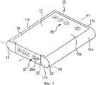
на фиг.3 показан вид в перспективе батарейного блока снизу в соответствии с вариантом воплощения настоящего изобретения;3 is a bottom perspective view of a battery pack in accordance with an embodiment of the present invention;
на фиг.4 показан вид в перспективе деталировки батарейного блока в соответствии с вариантом воплощения настоящего изобретения;4 is a perspective view of a detail of a battery pack in accordance with an embodiment of the present invention;
на фиг.5А показан вид спереди батарейного блока в соответствии с вариантом воплощения настоящего изобретения, и на фиг.5 В показан вид в плане подложки со слоем межсоединений в соответствии с вариантом воплощения настоящего изобретения;FIG. 5A is a front view of a battery pack in accordance with an embodiment of the present invention, and FIG. 5B is a plan view of a substrate with an interconnect layer in accordance with an embodiment of the present invention;
на фиг.6 показан вид в поперечном сечении модуля выводов;6 shows a cross-sectional view of a terminal module;
на фиг.7 показан вид сбоку батарейного блока в соответствии с вариантом воплощения настоящего изобретения;7 shows a side view of a battery pack in accordance with an embodiment of the present invention;
на фиг.8 показан пример схемы соединений батарейного блока в соответствии с вариантом воплощения настоящего изобретения;on Fig shows an example of the connection diagram of the battery pack in accordance with a variant embodiment of the present invention;
на фиг.9 показана блок-схема последовательности операций, представляющая пример процесса сборки батарейного блока в соответствии с вариантом воплощения настоящего изобретения;Fig. 9 is a flowchart showing an example of a battery pack assembly process in accordance with an embodiment of the present invention;
на фиг.10 показан вид в перспективе части электрических контактов модуля установки батареи, в который устанавливают батарейный блок в соответствии с вариантом воплощения настоящего изобретения;figure 10 shows a perspective view of part of the electrical contacts of the battery installation module into which the battery pack is installed in accordance with an embodiment of the present invention;
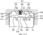
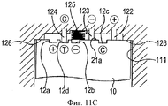
на фиг.11А показан вид в разрезе, представляющий состояние, в котором батарейный блок в соответствии с вариантом воплощения настоящего изобретения устанавливают в модуль для установки в цифровую фотокамеру, на фиг.11В показан вид в разрезе, представляющий состояние, в котором батарейный блок в соответствии с вариантом воплощения настоящего изобретения правильно установлен в модуль для установки в цифровую фотокамеру, и на фиг.11С показан вид в разрезе, представляющий состояние, в котором батарейный блок в соответствии с вариантом воплощения настоящего изобретения установлен в блок для установки в цифровую фотокамеру в перевернутом состоянии;FIG. 11A is a sectional view showing a state in which a battery pack according to an embodiment of the present invention is installed in a module for mounting in a digital camera; FIG. 11B is a sectional view showing a state in which the battery pack is in accordance with an embodiment of the present invention is correctly installed in a module for mounting in a digital camera, and FIG. 11C is a sectional view showing a state in which a battery pack according to an embodiment is implemented I of the present invention is installed in a digital camera upside unit for installation;
на фиг.12 показан вид в перспективе зарядного устройства, которое заряжает батарейный блок в соответствии с вариантом воплощения настоящего изобретения; и12 is a perspective view of a charger that charges a battery pack in accordance with an embodiment of the present invention; and
на фиг.13А показан вид в разрезе, представляющий состояние, в котором батарейный блок в соответствии с вариантом воплощения настоящего изобретения правильно установлен в модуль для установки в зарядное устройство, и на фиг.13В показан вид в разрезе, представляющий состояние, в котором батарейный блок в соответствии с вариантом воплощения настоящего изобретения установлен в модуль для установки в зарядное устройство в перевернутом состоянии.FIG. 13A is a sectional view showing a state in which the battery pack according to an embodiment of the present invention is correctly installed in the module for installation in the charger, and FIG. 13B is a sectional view representing the state in which the battery pack in accordance with an embodiment of the present invention is installed in a module for installation in a charger in an inverted state.
Осуществление изобретенияThe implementation of the invention
Батарейный блок в соответствии с вариантом воплощения настоящего изобретения будет описан ниже со ссылкой на приложенные чертежи.A battery pack in accordance with an embodiment of the present invention will be described below with reference to the attached drawings.
На фиг.1 показан вид в перспективе батарейного блока 10 в соответствии с вариантом воплощения настоящего изобретения, когда батарейный блок 10 устанавливают в цифровую фотокамеру 100, представляющую собой электронное устройство. Цифровая фотокамера 100 имеет практически прямоугольный тонкий корпус 101. Модуль 102 объектива, включающий в себя множество линз, таких как линза изменения фокусного расстояния и конденцерная линза, предусмотрен на передней стороне 101а корпуса 101. Спусковая кнопка 103 расположена рядом с одним углом на верхней стороне 101b корпуса 101. Спусковая кнопка 103 предназначена для съемки изображения предмета. Модуль 104, излучающий свет при фотографической съемке со вспышкой, расположен ближе к верхней стороне 101b на передней стороне 101a корпуса 101. Окно 105 видоискателя расположено рядом с модулем 104, излучающим свет. Установочное гнездо 106 расположено практически в центре в направлении ширины на нижней поверхности 101с корпуса 101. В установочное гнездо 106 можно устанавливать штатив и т.д.1 is a perspective view of a
Практически прямоугольный паз 107 для батарейного блока предусмотрен на нижней поверхности 101с корпуса 101 фотокамеры. Паз 107 для батареи имеет приблизительно такой же размер и форму, что и передняя сторона батарейного блока 10, который устанавливают в паз 107. Крышка 108 предусмотрена для открывания и закрывания паза 107. Паз 109, в который вставляют карту 110 памяти, расположен рядом с пазом 107 в области, открываемой и закрываемой крышкой 108. Карта 110 памяти представляет собой внешнее устройство-накопитель. Модуль 111 для установки батарейного блока расположен в корпусе 101 фотокамеры смежно с пазом 107. Фиксатор 112 расположен рядом с пазом 107. Фиксатор 112 в установленном положении батарейного блока 10 удерживает его в модуле 111. Когда батарейный блок 10 устанавливают в модуль 111, фиксирующий элемент 112 зацепляется с углом задней стороны 11d батарейного блока 10 для предотвращения его выпадения из модуля 111 под действием упругости электрических контактов или пружины. В частности, фиксатор 112 установлен с возможностью поворота рядом с пазом 107. Один конец фиксатора 112 обращен к пазу 107 и контактирует с углом задней стороны 11d батарейного блока 10, установленного в модуль 111, для удержания батарейного блока 10 в установленном положении.An almost rectangular groove 107 for the battery pack is provided on the bottom surface 101c of the camera body 101. The groove 107 for the battery is approximately the same size and shape as the front side of the
Для изъятия батарейного блока 10 из модуля 111 фиксатор 112 отводят от паза 107 для разъединения угла задней стороны 11d батарейного блока 10 от фиксатора 112. В результате, батарейный блок 10 выталкивается из паза 107 батареи под действием упругих сил.To remove the
Батарейный блок 10 содержит, например, ионно-литиевый полимерный элемент питания. В частности, как показано на фиг.2 и 3, батарейный блок 10 имеет корпус 11, в котором расположен ионно-литиевый полимерный элемент питания 29. Корпус 11 имеет практически прямоугольную форму в плане. Корпус 11 имеет плоскую верхнюю сторону 11а, нижнюю сторону 11b, переднюю сторону 11с и заднюю сторону 11d и круглые боковые стороны 11е и 11f, выступающие наружу. Корпус 11 имеет примерно одинаковую толщину, от передней стороны 11с до задней стороны 11d. Корпус 11 выполнен симметричным относительно центральной линии Р1 в направлении ширины корпуса 11 блока и также симметричным относительно центральной линии Р2 в направлении толщины корпуса 11, если смотреть с его передней стороны 11с, на которой расположен модуль 12 выводов. Переднюю сторону 11с корпуса 11 блока вставляют в паз 107 цифровой фотокамеры 100. Модуль 12 выводов прижимают, вводя его в контакт с частью электрического контакта на нижней стороне модуля 111 для электрического подключения к цифровой фотокамере 100. В соответствии с этим батарейный блок 10 можно легко извлекать из модуля 111, даже если батарейный блок 10 будет вставлен в паз 107 в перевернутом состоянии.The
В соответствии с вариантом воплощения настоящего изобретения необходимо, чтобы корпус 11 блока имел приблизительно одинаковую толщину от передней стороны 11с до задней стороны 11d. Кроме того, необходимо, чтобы корпус 11 блока был симметричным относительно центральной линии Р1 в направлении ширины и также был симметричным относительно центральной линии Р2 в направлении толщины, если рассматривать с передней стороны 11с, на которой расположен модуль 12 выводов. Однако могут быть предусмотрены какие-либо небольшие выемки, выступы, пазы на передней стороне 11с и/или на задней стороне 11d для различных целей, таких как предотвращение неправильной вставки и определение типа батареи. Батарейный блок 10 имеет форму, позволяющую устанавливать его в модуль 111 как минимум «вверх ногами» и «вверх дном».According to an embodiment of the present invention, it is necessary for the
В частности, как показано на фиг.4, корпус 11 блока имеет форму практически прямоугольной плоской трубки 13. Трубка 13 выполнена, например, из металла, такого как алюминий, на поверхности которой расположена нейлоновая пластиковая пленка. Нейлоновая пластиковая пленка предназначена для электрической изоляции и защиты поверхности трубки 13. Трубка 13 снабжена также полипропиленовой пластиковой пленкой, обладающей высокими изоляционными свойствами и гибкостью, которая установлена внутри таким образом, что переднее отверстие 13а и заднее отверстие 13b трубки 13 могут быть соединены с верхней крышкой 14 и нижней крышкой 15, закрывающими отверстия 13а и отверстие 13b путем термосварки. В трубке 13 содержится элемент 29, который представляет собой ионно-литиевый полимерный элемент питания. Положительный вывод 16 и отрицательный вывод 17 проходят через отверстие 13а на передней стороне.In particular, as shown in FIG. 4, the
Держатель 19, на котором установлена подложка 18 со слоем межсоединений, закреплена в отверстии 13а на передней стороне. Верхняя крышка 14 установлена на держателе 19. Подложка 18 представляет собой жесткую печатную плату, имеющую приблизительно такую же форму и размеры, как и отверстие 13а на передней стороне. На одной стороне подложки 18 в направлении держателя 19 расположено несколько электронных компонентов, в частности устройство 18а защиты, устройство 18b идентификации и полевой транзистор 18с. Схема защиты элемента 29 предусмотрена в устройстве 18а защиты. Схема идентификации батарейного блока 10 в цифровой фотокамере 100 предусмотрена в устройстве 18b идентификации. Устройство 18с управляет зарядом. Положительный контакт 18d и отрицательный контакт 18е также установлены на подложке 18. Положительный вывод 16 элемента 29 батареи закреплен на положительном контакте 18d путем сварки, такой как контактная сварка. Отрицательный вывод 17 элемента 29 закреплен на отрицательном контакте 18е через устройство 18f c положительным температурным коэффициентом (ПТК) путем сварки, такой как контактная сварка. Устройство 18f выполнено таким, что оно практически отключает ток, протекающий через элемент 29, когда температура элемента 29 батареи становится выше установленной и при этом резко увеличивается электрическое сопротивление.The
Подложка 18 со слоем межсоединений, на которой установлены электронные компоненты, как описано выше, и на которой закреплены положительный и отрицательный выводы 16 и 17 через устройство 18f, расположена и установлена на одной стороне держателя 19, то есть на стороне, противоположной элементу 29. Держатель 19 вставлен в отверстие 13 а на передней стороне трубки 13. Вырезы 19а выполнены на одной более длинной и более узкой стороне держателя 19. Вырезы 19а выполнены так, что они окружают положительный вывод 16 и отрицательный вывод 17 вокруг держателя 19, в направлении стороны которого установлена подложка 18. Держатель 19 выполнен, например, из полипропиленового пластикового материала. Держатель 19, на котором установлена верхняя крышка 14, закреплен в отверстии 13а на передней стороне трубки 13 и соединен с верхней крышкой 14 путем термосварки.A
На фиг.5А показан вид спереди батарейного блока 10 в соответствии с вариантом воплощения настоящего изобретения, и на фиг.5В показан вид в плане подложки 18 со слоем межсоединений. Как показано на фиг.5А и 5 В, положительный вывод 12а, отрицательный вывод 12b, вывод 12 с управления, и вывод 12d детектирования температуры, образующие модуль 12 выводов, расположены на другой стороне подложки 18, то есть на стороне, направленной к верхней крышке 14. В частности, эти четыре вывода 12а-12d расположены в ряд на центральной линии Р2 в направлении ширины. Положительный вывод 12а, вывод 12d детектирования температуры и отрицательный вывод 12b расположены через равные интервалы с одной стороны от центральной линии Р1 в направлении ширины, и вывод 12 с управления расположен с другой стороны от центральной линии Р1 в направлении ширины. Вывод 12с управления расположен несимметрично с положительным выводом 12а и отрицательным выводом 12b относительно центральной линии Р1. Вывод 12d детектирования температуры расположен симметрично с выводом 12с управления относительно центральной линии Р1. Поскольку отрицательный вывод 12b расположен с внутренней стороны, а положительный вывод 12а - с внешней стороны относительно вывода 12d детектирования температуры, расположенного между отрицательным выводом 12b и положительным выводом 12а, и вывод 12с управления расположен дальше всего от положительного вывода 12а, то такое расположение предотвращает ошибочное электрическое соединение положительного вывода 12а с выводом 12с управления.FIG. 5A is a front view of a
В соответствии с вариантом воплощения настоящего изобретения, положение вывода 12d детектирования температуры можно взаимно поменять местами с выводом 12с управления.According to an embodiment of the present invention, the position of the
Верхняя крышка 14 установлена на внешней стороне подложки 18, на которой предусмотрены выводы 12а-12d, как показано на фиг.4 и на фиг 5А и 5В. Верхнюю крышку 14 устанавливают в отверстие 13а на передней стороне трубчатого корпуса 13 так, что она закрывает отверстие 13а на передней стороне. Верхняя крышка 14 формирует переднюю сторону 11с корпуса 11. Верхняя крышка 14 изготовлена, например, из полипропиленового пластикового материала и соединена с передним отверстием 13а трубки 13 после ее установки путем термосварки.The
Как показано в фиг.2 и на фиг.4-6, верхняя крышка 14 имеет отверстия 14а-14d для выводов, через которые положительный вывод 12а, отрицательный вывод 12b, вывод 12с управления и вывод 12d детектирования температуры выходят наружу. В частности, положительный вывод 12а выходит наружу через отверстие 14а, отрицательный вывод 12b выходит наружу через отверстие 14b, вывод 12с управления выходит наружу через отверстие 14с и вывод 12d детектирования температуры выходит наружу через отверстие 14d. Каждое из отверстий 14а-14d для вывода имеет практически прямоугольную форму. Кроме того, как показано на фиг.6, каждое из отверстий 14а-14d имеет верхний и нижний сужающиеся участки 14е, наклоненные внутрь. Сужающиеся участки 14е предназначены для облегчения доступа электрических контактов, выполненных на нижней стороне модуля 111, к отверстиям 14а-14d для выводов и для улучшения их прижима с обеспечением контакта к выводам 12а-12d.As shown in FIGS. 2 and 4-6, the
Как показано на фиг.5а, промежуток 21а между отверстием 14b для отрицательного вывода 12b и отверстием 14с для вывода 12с управления выполнен более широким, чем промежуток 21b между отверстием 14а для положительного вывода 12а и отверстием 14d для вывода 12d детектирования температуры и чем промежуток 21с между отверстием 14d для вывода 12d детектирования температуры и отверстием 14b для отрицательного вывода 12b. Промежуток 21а используется как участок, с которым входит в контакт пружина, когда батарейный блок 10 загружают в модуль 111.5a, the
Отверстие 13b на обратной стороне трубки 13 закрыто нижней крышкой 15, как показано на фиг 3 и 4. Нижняя крышка 15 изготовлена, например, из полипропиленового пластикового материала и соединена с отверстием 13b на задней стороне трубки 13 путем термосварки. Участок 22 выемки для этикетки предусмотрен в центральной области, в направлении ширины нижней крышки 15. Один конец нижней крышки 15 используется как участок 23 соединения, с которым контактирует фиксатор 112, когда батарейный блок 10 установлен в модуль 111.The hole 13b on the back of the
После установки верхней крышки 14 и нижней крышки 15 на трубку 13 приклеивают этикетку 24 к верхней крышке 11а, задней крышке 11d и нижней поверхности 11b корпуса 11, как показано на фиг 2-4. Этикетка 24 изготовлена, например, из пластикового листа из полиэтилентерефталата, и с нижней стороны этого пластикового листа нанесена клеящая пленка. Сторона, противоположная клеящей пленке, используется как сторона для печати. На этикетке 24 участок, соответствующий задней стороне 11d корпуса 11 блока, выполнен более узким, так, что он приблизительно имеет такую же ширину, как и участок 22 выемки для этикетки. Этикетка 24, приклеенная на верхней поверхности 11а, на задней поверхности 11d и на нижней поверхности 11b корпуса 11 блока, прижимает нижнюю крышку 15, закрепленную путем термосварки на трубке 13, предотвращая выпадение нижней крышки 15.After installing the
Поскольку участок, на котором приклеена этикетка 24 на задней стороне 11d корпуса 11, не выступает относительно окружающих участков, длина батарейного блока 10 не увеличивается, способствуя уменьшению размера батарейного блока 10. Кроме того, можно предотвратить царапание или свертывание этикетки 24, когда батарейный блок 10 устанавливают в модуль 111 или в зарядное устройство или извлекают его из них. Благодаря тому что участок 22 выемки для этикетки предусмотрен на задней стороне 11d корпуса 11 блока, в месте, где приклеена этикетка 24, обеспечивается, практически, ровный участок с окружающими участками, что улучшает тактильное ощущение.Since the portion on which the
Благодаря тому что ширина этикетки 24, соответствующая задней стороне 11d корпуса 11, выполнена более узкой, увеличивается площадь участков, расположенных с обеих сторон от этикетки 24, и участок 23 соединения, с которым контактирует фиксатор 112, может быть в достаточной степени увеличен в размере.Due to the fact that the width of the
Ниже, со ссылкой на фиг.2 и 3, будут описаны надписи на этикетке 24. Индикатор 25а ориентации, обозначенный как Δ, предусмотрен на задней стороне 11d корпуса 11 блока. Индикатор 25а ориентации обозначает положение, в котором батарейный блок 10 вставляют в паз 107. Как показано на фиг.1, индикатор 25а ориентации может быть совмещен с индикатором 25b ориентации, который обозначен как Δ и который предусмотрен рядом с пазом 107 для вставки батарейного блока 10 в правильном положении (а не наоборот).Below, with reference to FIGS. 2 and 3, labeling 24 will be described.
Индикатор 26 направления вставки, обозначенный как Δ, предусмотрен на верхней стороне 11а корпуса 11 блока. Индикатор 26 обозначает направление, в котором батарейный блок 10 вставляют в паз 107. Пользователь может по индикатору 26 определить правильность установки в направлении передней стороны 11с, на которой расположен модуль 12 выводов. Индикатор 26, направленный на переднюю сторону 11с, предусмотрен на верхней стороне 11а для визуального обозначения передней стороны 11с, которая должна быть направлена к пазу 107.An
Модуль 27 обозначения функции расположен на задней стороне 11d корпуса 11. На модуле 27 отображены обозначения функций, соответствующих выводам модуля 12. В частности, на модуле 27 предусмотрены знак +, буква Т, знак - и буква С, обозначающие функции положительного вывода 12а, вывода 12d детектирования температуры, отрицательного вывода 12b и вывода 12с управления, соответственно. Интервал между знаком - и буквой С выполнен более широким, чем другие интервалы, обозначенные знаками. Модуль 27 обозначения функции позволяет пользователю сверять функции выводов.The
Благодаря тому что индикатор 25а ориентации и модуль 27 обозначения функции, предусмотренный на задней стороне 11d корпуса 11, являющейся наиболее видимой для пользователя, когда батарейный блок 10 вставляют в паз 107, можно предотвратить неправильную вставку.Due to the
Модуль 28 обозначения функции предусмотрен ближе к передней стороне 11с на нижней поверхности 11b корпуса 11 блока. На модуле 28 обозначены функции, соответствующие выводам модуля 12 выводов. В частности, на модуле 28 предусмотрены обозначения знак +, буква Т, знак - и буква С, обозначающие функции положительного вывода 12а, вывода 12d детектирования температуры, отрицательного вывода 12b и вывода 12с управления, соответственно. Интервал между знаком - и буквой С выполнен более широким, чем другие интервалы, обозначенные знаками. Модуль 28 позволяет пользователю сверять функции выводов.
Знаки или символы, обозначенные на индикаторе 25а ориентации, индикаторе 25b ориентации, индикаторе 26 направления вставки, модуля 27 обозначения функции и модуля 28 обозначения функции, не ограничиваются такими обозначениями, как символ Δ и знак +.Signs or symbols indicated on the
Верхняя крышка 14 выполнена несколько большей, чем передняя сторона 11с, на величину, обозначенную позицией 20 на фиг.7 так, что верхняя крышка 14 несколько выступает за пределы передней стороны 11с корпуса 11 блока, после приклеивания этикетки 24. Аналогично, нижняя крышка 15 выполнена несколько большей, чем задняя крышка 11d, на величину, обозначенную номером 20 ссылочной позиции на фиг.7 таким образом, что нижняя крышка 15 несколько выступает за пределы задней стороны 11d корпуса 11 блока, после приклеивания этикетки 24. Это позволяет предотвратить царапание информативной стороны этикетки 24 в результате трения, например, о внутреннюю сторону корпуса 11 блока, что может сделать этикетку 24 нечитаемой или свернуть этикетку 24, когда батарейный блок 10 загружают в модуль 111 или извлекают его из него.The
На фиг.8 показан пример схемы электрических соединений батарейного блока 10, выполненного, как описано выше. В батарейном блоке 10, показанном на фиг.8, положительный контактный вывод 16 элемента 29 батареи подключен последовательно к положительному выводу 12а подложки 18 со слоем межсоединений. Отрицательный контактный вывод 17 элемента 29 батареи подключен последовательно к отрицательному выводу 12b подложки со слоем 18 межсоединений через устройство 18f. Полевые транзисторы Q1 и Q2, образующие устройство 18с, подключены между устройством 18f и отрицательным выводом 12b подложки со слоем 18 межсоединений.On Fig shows an example of the electrical connections of the
Положительный силовой вывод защитной цепи 31, которая состоит из защитного устройства 18а, установленного на подложке 18, подключен между положительным выводом 12а и положительным контактным выводом 16 элемента 29 батареи. Отрицательные силовые выводы защитной цепи 31 подключены между устройством 18f и Q1, и между отрицательным выводом 12b и Q2. Выводы управления защитной цепи 31 подключены к затворам Q1 и Q2. Защитная цепь 31 отслеживает напряжения между выводами и отключает Q1 и/или Q2 в случае перезаряда или чрезмерного разряда для отключения заряда.The positive power terminal of the
Вывод управления схемы 32 идентификации, состоящей из устройства 18b идентификации, установленного на подложке 18, подключен к выводу 12 с управления подложки 18, и отрицательный силовой вывод схемы 32 идентификации подключен к отрицательному выводу 12b подложки со слоем 18 межсоединений. Термистор 33, который представляет собой устройство детектирования температуры, подключен между выводом 12d детектирования температуры и отрицательным выводом 12b подложки со слоем 18 межсоединений для подачи сигнала температуры в устройство заряда через вывод 12d детектирования температуры.The
Поскольку схема 32 идентификации управляется в соответствии с сигналом, передаваемым из цифровой фотокамеры 100 в схеме, показанной на фиг.8, возможно предотвратить потребление энергии от элемента 29 батареи, благодаря генерированию энергии дежурного режима, когда блок 10 батареи не используется. Кроме того, поскольку температуру детектируют с помощью термистора 33, который отделен от устройства 18а защиты, которое составляет защитную цепь 31, в схеме, представленной на фиг.8, становится возможным уменьшить стоимость устройства 18а защиты.Since the
На фиг.9 показана блок-схема последовательности операций, представляющая пример процесса сборки батарейного блока 10, выполненного, как описано выше. Как показано на фиг.9, на этапе S1, устройство 18f устанавливают в оправку. На этапе S2 подложку 18, на которой установлены электронные компоненты, включающие в себя защитное устройство 18а, устройство 18b идентификации, устройство 18с и термистор 33, устанавливают в оправку. На этапе S3, корпус 11 блока устанавливают в оправку. Корпус 11 блока состоит из трубки 13, в которую установлен элемент 29 батареи, и положительный контактный вывод 16, и отрицательный контактный вывод 17 которого отрезаны на заданную длину. На этапе S4 положительный контактный вывод 16, продолжающийся от элемента 29 батареи, соединяют с положительным лепестком 18d подложки со слоем 18 межсоединений, используя контактную сварку, и отрицательный контактный вывод 17, продолжающийся от элемента 29 батареи, соединяют с отрицательным лепестком 18е подложки 18 через устройство 18f, используя контактную сварку. На этапе S5 положительный контактный вывод 16 и отрицательный контактный вывод 17 после контактной сварки складывают с приданием им заданной формы.FIG. 9 is a flowchart showing an example of the assembly process of the
На этапе S6 подложку 18 устанавливают в держатель 19. На этапе S7 держатель 19 устанавливают на верхнюю крышку 14. На этапе S8 держатель 19 приваривают к верхней крышке 14, используя импульсную сварку, и держатель 19, приваренный к верхней крышке 14, устанавливают в отверстие 13а на передней стороне трубчатого корпуса 13. Как показано на фиг.4, верхняя крышка 14 установлена на держателе 19 с использованием установочных выступов 19с в сквозные отверстия 19b с обеих сторон держателя 19 и в результате приваривания выступов 19с к держателю 19 с использованием импульсной сварки. Выемки 18g с обеих сторон подложки 18 соединяются с выступами 19с на задней стороне верхней крышки 14 между верхней крышкой 14 и держателем 19. На этапе S9 нижнюю крышку 15 устанавливают в отверстие 13b с обратной стороны трубки 13. На этапе S10 верхнюю крышку 14 и нижнюю крышку 15 приваривают термосваркой к трубке 13.In step S6, the
На этапе S11 этикетку 24, изготовленную по заказу, устанавливают и приклеивают к верхней стороне 11а, задней стороне 11d и к нижней стороне 11b корпуса 11 блока, отверстию 13а на передней стороне и отверстию 13b на задней стороне, которые закрыты верхней крышкой 14 и нижней крышкой 15, соответственно.In step S11, a
Способ установки батарейного блока 10, собранного, как описано выше, в модуль 111 цифровой фотокамеры 100 будет описан ниже со ссылкой на фиг.1, 10 и 11А-11С. Как показано на фиг.1 и фиг.11А, батарейный блок 10 вставляют в паз 107 в направлении, обозначенном индикатором 26 на верхней стороне 11а корпуса 11, с символом Δ индикатора 25а ориентации на задней стороне 11d корпуса 11 блока, который совмещают с индикатором 25b ориентации, предусмотренным рядом с пазом 107.The method of installing the
Корпус 11 батарейного блока 10 выполнен симметричным относительно центральной линии Р1 в направлении ширины и симметричным относительно центральной линии Р2 в направлении толщины. Паз 107 и модуль 111 выполнены в соответствии с симметрией батарейного блока 10. Например, если корпус 11 будет вставлен в паз 107 в перевернутом положении без учета обозначений индикатора 25а, то он и будет расположен в модуле 111 в перевернутом состоянии. В соответствии с этим, индикатор 25а будет расположен на задней стороне 11d, которая не будет видна пользователю, а индикатор 26, предусмотренный на верхней стороне 11а, будет хорошо виден, что будет свидетельствовать о неправильной вставке.The
На фиг.10 показан вид в перспективе части 121 электрического контакта модуля 111, в который устанавливают батарейный блок 10. Часть 121 электрического контакта выполнена на нижней стороне модуля 111 и электрически соединяется с батарейным блоком 10 при его установке. Положительный контакт 122, отрицательный контакт 123 и контакт 124 управления, соответствующие положительному выводу 12а, отрицательному выводу 12b и выводу 12с управления, соответственно, модуля 12 выполнены на части 121 электрического контакта, на нижней стороне модуля 111. Каждый из контактов 122, 123 и 124 представляет собой, например, электропроводную пластину, упруго изогнутую с приданием ей формы резкого изгиба. Положительный вывод 12а прижимается с установлением контакта с положительным контактом 122. Отрицательный вывод 12b прижимается с установлением контакта с отрицательным контактом 123. Вывод 12с прижимается с установлением контакта с контактом 124 управления. Поскольку часть 121 электрического контакта используется, когда питание подается из батарейного блока 10 в цифровую фотокамеру 100, контакт детектирования температуры не предусмотрен для вывода 12d детектирования температуры, который не обязателен для разряда. В соответствии с этим положительный контакт 122 отнесен от отрицательного контакта 123 на расстояние, соответствующее непредусмотренному контакту детектирования температуры. Участок, окруженный пунктирной линией на фиг.10, соответствует выводу 12d детектирования температуры.Figure 10 shows a perspective view of the
Отрицательный контакт 123 отнесен на некоторое расстояние от контакта 124 управления и в промежутке между ними расположена пружина 125 для выталкивания батарейного блока 10 из модуля 111. Пружина 125 представляет собой, например, витую пружину. Пружина 125 контактирует с участком, который представляет собой промежуток 21а для выталкивания батарейного блока 10 из модуля 111.The
Когда батарейный блок 10 устанавливают в модуль 111, как показано на фиг.11 В, положительный вывод 12а прижимается с установлением контакта к положительному контакту 122, отрицательный вывод 12b прижимается с установлением контакта к отрицательному контакту 123, и вывод 12с прижимается с установлением контакта к контакту 124 управления. Это позволяет подавать от батарейного блока 10 питание к цифровой фотокамере 100. Кроме того, сигнал управления от цифровой фотокамеры 100 передают в схему 32 идентификации через вывод 12с управления для обеспечения возможности, например, идентификации батарейного блока 10 цифровой фотокамерой 100. Например, если цифровая фотокамера 100 идентифицирует установленный батарейный блок 10 как нормальный, устройство 18с включается для подачи питания. Батарейный блок 10 вставляют в модуль 111 до тех пор, пока углы передней стороны 11с корпуса 11 блока не прижмутся к участкам 126 упора. Участки 126 упора выполнены на углах нижней стороны, на которой расположена часть 121, и приподняты над нижней стороной. Участки 126 упора выполнены для исключения повреждения части 121 электрического контакта в результате слишком глубокой вставки батарейного блока 10 в модуль 111.When the
Батарейный блок 10 находится в установленном состоянии, когда он зафиксирован фиксатором 112 и пружина 125 сжата. Батарейный блок 10 выталкивается из паза 107 для батареи, под действием упругой силы пружины 125, когда батарейный блок 10 не зафиксирован фиксатором 112.The
Поскольку корпус 11 выполнен симметричным относительно центральной линии Р1 в направлении ширины и симметричным относительно центральной линии Р2 в направлении толщины, а паз 107 и модуль 111 установки батареи выполнены в соответствии с симметрией батарейного блока 10, корпус 11 может быть вставлен в паз 107 в перевернутом состоянии, если не следовать обозначениям индикатора 25а ориентации. В таком случае, как показано на фиг.11С, положительный контакт 122 и отрицательный контакт 123 части 121 электрического контакта блока 111 входят в контакт с участками, не имеющими соответствующих выводов на одной стороне относительно центральной линии Р1 в направлении ширины на передней стороне 11с корпуса 11. Контакт 124 управления будет находиться в контакте с выводом 12d детектирования температуры с другой стороны относительно центральной линии Р1 в направлении ширины на передней стороне 11с корпуса 11. Это обусловлено тем, что вывод 12с управления расположен несимметрично положительному выводу 12а и отрицательному выводу 12b относительно центральной линии Р1, в направлении ширины корпуса 11, но симметрично выводу 12d детектирования температуры относительно центральной линии Р1 в направлении ширины корпуса 11.Since the
Поэтому даже, если батарейный блок 10 будет вставлен в паз 107 в перевернутом состоянии до тех пор, пока углы на передней стороне 11с корпуса 11 не упрутся в участки 126, эти участки 126 могут предотвратить чрезмерный изгиб части 121 электрического контакта, в частности положительный контакт 122 и отрицательный контакт 123, которые электрически не соединены с модулем 12, и они не будут повреждены в результате вставки батарейного блока 10 слишком глубоко в модуль 111. Поскольку положительный вывод 12а и отрицательный вывод 12b батарейного блока 10 не находится в контакте ни с каким контактом части 121 электрического контакта модуля 111, напряжение батареи не будет приложено к неправильным контактам. В результате, становится возможным предотвратить повреждение или поломку цифровой фотокамеры 100 вследствие установки в нее несоответствующего предмета. Хотя вывод 12d детектирования температуры будет находиться в контакте с контактом 124 управления модуля 111, напряжение не будет передано от контакта 124 управления к контакту 12d детектирования температуры и наоборот. Таким образом, становится возможным предотвратить поломку батарейного блока 10 и цифровой фотокамеры 100, даже если он будет установлен в модуль 111 в перевернутом состоянии.Therefore, even if the
Если батарейный блок 10 будет вставлен в паз 107 в перевернутом состоянии, вся пружина 125 или ее часть будет перекрыта отрицательным выводом 12b. Даже в таком случае, поскольку верхний конец пружины 125 выполнен большим, чем отверстие 14b вывода, пружина 125 примыкает к краям отверстия 14b и не входит в непосредственной контакт с отрицательным выводом 12b, что предотвращает его повреждение. Поскольку ток не протекает через пружину 125, даже если пружина 125 находится в контакте с отрицательным выводом 12b, становится возможным предотвратить поломку батарейного блока 10 и цифровой фотокамеры 100.If the
Верхний конец пружины 125 может быть меньшим, чем отверстие 14b вывода для отрицательного вывода 12b. Даже в этом случае, поскольку ток не протекает между отрицательным выводом 12b и пружиной 125, становится возможным предотвратить поломку батарейного блока 10 и цифровой фотокамеры 100. Пружина 125 может быть расположена на участке, с которым входит в контакт промежуток 21а контактного участка, когда батарейный блок 10 вставляют в паз 107 в перевернутом состоянии.The upper end of the
Батарейный блок 10 заряжается с помощью зарядного устройства, отдельного от цифровой фотокамеры 100, как показано на фиг.12. Зарядное устройство 130, показанное на фиг.12, имеет основной корпус 131, в котором выполнен модуль 132 установки батареи. Модуль 132 установки батареи имеет приблизительно такое же открытое пространство, что и области на верхней стороне 11а и на нижней стороне 11b корпуса блока 11, и имеет приблизительно такую же глубину и толщину, как и у корпуса 11. В модуле 132 установки батареи предусмотрен вырез 133 для облегчения установки батарейного блока 10 в модуль 132 и для облегчения его удаления из модуля 132.The
Часть 134 электрического контакта выполнена на задней стороне модуля 132. Задняя сторона расположена напротив модуля 12 выводов с передней стороны 11с устанавливаемого батарейного блока 10. Положительный контакт 135, контакт 136 детектирования температуры и отрицательный контакт 137, соответствующие положительному выводу 12а, выводу 12d детектирования температуры и отрицательному выводу 12b, выполнены в части 134. Каждый из контактов 135, 136, 137 представляет собой, например, электропроводную пластинку, упруго изогнутую с приданием ей формы резкого изгиба. Положительный вывод 12а прижимается с установлением контакта к положительному контакту 135. Вывод 12d детектирования температуры прижимается с установлением контакта к контакту 136 детектирования температуры. Отрицательный вывод 12b прижимается с установлением контакта к отрицательному контакту 137. Поскольку часть 134 электрического контакта используется при зарядке батарейного блока 10, контакт управления не предусмотрен для вывода 12с, который не нужен для заряда, в отличие от цифровой фотокамеры 100. В соответствии с этим, все контакты 135, 136 и 137 части 134 электрического контакта предусмотрены с одной стороны относительно центральной линии Р1 в направлении ширины на передней стороне 11с.An
Когда батарейный блок 10 необходимо вставить в модуль 132 зарядного устройства 130, пользователь может свериться с модулем 27 обозначения функции, который расположен на задней стороне 11d, и с индикатором 26 направления вставки на верхней стороне 11а для предотвращения установки батарейного блока 10 в перевернутом состоянии.When the
Когда батарейный блок 10 устанавливают в модуль 132, как показано на фиг.13А, положительный вывод 12а прижимается с установлением контакта к положительному контакту 135, вывод 12d детектирования температуры прижимается с установлением контакта к контакту 136 детектирования температуры, и отрицательный вывод 12b прижимается с установлением контакта к отрицательному контакту 137. Вследствие этого зарядное устройство 130 может передать напряжение заряда к батарейному блоку 10. Поскольку контакт 136 детектирования температуры находится в контакте с выводом 12d детектирования температуры, зарядное устройство 130 детектирует сигнал температуры, передаваемый от термистора 33, для обеспечения заряда в соответствии с сигналом температуры. Батарейный блок 10 вставляют в модуль 132 до тех пор, пока углы передней стороны 11с корпуса 11 не упрутся в участки 138 упора. Участки 138 упора выполнены на углах задней стороны, на которой расположена часть 134, и приподняты от задней стороны. Участки 138 упора предназначены для предотвращения повреждения части 134 при вставке батарейного блока 10 слишком глубоко в модуль 132.When the
Когда батарейный блок 10 устанавливают в модуль 132 в перевернутом состоянии до тех пор, пока углы передней стороны 11с корпуса 11 не примкнут к участкам 138, эти участки позволяют предотвратить слишком сильный изгиб части 134 и ее повреждение, в частности, положительного контакта 135 и отрицательного контакта 137. Положительный контакт 135 и отрицательный контакт 137 находится в контакте с участками, не имеющими соответствующих выводов на другой стороне относительно центральной линии Р1 в направлении ширины на передней стороне 11с корпуса 11. Контакт 136 детектирования температуры контактирует с выводом 12с управления на другой стороне относительно центральной линии Р1 в направлении ширины на передней стороне 11с корпуса 11 блока. Это обусловлено тем, что вывод 12с управления расположен несимметрично положительному выводу 12а и отрицательному выводу 12b относительно центральной линии Р1 в направлении ширины корпуса 11, но симметрично выводу 12d детектирования температуры относительно центральной линии Р1 в направлении ширины корпуса 11.When the
Поскольку положительный вывод 12а и отрицательный вывод 12b не находятся в контакте с каким-либо из контактов части 134, то даже если батарейный блок 10 будет установлен в модуль 132 в перевернутом состоянии, напряжение заряда не будет подано на несоответствующий контакты. Вследствие этого становится возможным предотвратить поломку или повреждение батарейного блока 10, связанные с тем, что несоответствующий предмет будет установлен в модуль 132. Хотя вывод 12с управления находится в контакте с контактом 136 детектирования температуры, напряжение не будет подано от контакта 136 детектирования температуры на вывод 12с управления и поэтому становится возможным предотвратить поломку цепи 32 идентификации, подключенной к выводу 12с управления.Since the
Хотя батарейный блок 10 заряжается с использованием специального зарядного устройства в соответствии с приведенным выше описанием, батарейный блок 10 может быть заряжен с использованием цифровой фотокамеры 100. В этом случае цифровая фотокамера 100 снабжена зарядной цепью, и контакт детектирования температуры выполнен между положительным контактом 122 и отрицательным контактом 123 в части 121.Although the
Поскольку корпус 11 выполнен, как описано выше, симметричным относительно центральной линии Р1 в направлении ширины и симметричным относительно центральной линии Р2 в направлении толщины, то батарейный блок 10 можно легко извлекать из модуля 111, даже если батарейный блок 10 будет установлен в модуль 111 в перевернутом состоянии. Кроме того, индикатор 25а ориентации расположен на задней стороне 11d, которая лучше всего видна пользователю, когда батарейный блок 10 вставлен в паз 107, а на верхней стороне 11а расположен индикатор 26 направления вставки, который хорошо виден, что предотвращает неправильную вставку.Since the
Поскольку положительный вывод 12а и отрицательный вывод 12b не находятся в контакте с каким-либо контактом части 121, как в примере, показанном на фиг.11С, то даже, если батарейный блок 10 будет установлен в модуль 111 в перевернутом состоянии, напряжение батареи не будет приложено к несоответствующим контактам. В результате, становится возможным предотвратить повреждение и поломку цифровой фотокамеры 100 в связи с нахождением в ней несоответствующего предмета. Хотя вывод 12d детектирования температуры находится в контакте с контактом 124 управления модуля 111, напряжение не будет передано от контакта 124 управления к выводу 12d детектирования температуры и наоборот. Вследствие этого становится возможным предотвратить повреждение батарейного блока 10 и цифровой фотокамеры 100, даже если он будет вставлен в модуль 111 в перевернутом состоянии.Since the
Если батарейный блок 10 вставлен в модуль 111 в перевернутом состоянии, вся или часть пружины 125 модуля 111 установки батареи будет перекрыта отрицательным выводом 12b. Даже в этом случае, поскольку верхний конец пружины 125 выполнен большим, чем отверстие 14b вывода, пружина 125 упирается в края отверстия 14b вывода, предотвращая, таким образом, повреждение отрицательного вывода 12b. Поскольку ток не протекает через пружину 125, даже если пружина 125 находится в контакте с отрицательным выводом 12b, становится возможным предотвратить поломку батарейного блока 10 и цифровой фотокамеры 100.If the
Когда батарейный блок 10 требуется установить в модуль 132, пользователь может свериться с модулем 27 обозначения функции на задней стороне 11d и с индикатором 26 направления вставки на верхней поверхности 11, предотвращая, таким образом, установку батарейного блока 10 в перевернутом состоянии. Кроме того, как показано на фиг.13В, поскольку положительный вывод 12а и отрицательный вывод 12b батарейного блока 10 не находятся в контакте с каким-либо контактом части 134, то даже если батарейный блок 10 установлен в модуль 132 в перевернутом состоянии, напряжение заряда не будет приложено к несоответствующим контактам. В результате, становится возможным предотвратить поломку или повреждение батарейного блока 10, ввиду того, что несоответствующие предметы не находятся в контакте с батарейным блоком 10. Хотя вывод 12с управления находится в контакте с контактом 136 детектирования температуры модуля 132, напряжение не передается от контакта 136 детектирования температуры к выводу 12с управления и поэтому становится возможным предотвратить отказ цепи 32 идентификации, подключенной к выводу 12с управления.When the
В батарейном блоке 10 этикетка 24, приклеенная к верхней поверхности 11а, задней поверхности 11d и нижней поверхности 11b корпуса 11 блока прижимает нижнюю крышку 15, установленную способом термосварки на трубке 13, как показано на фиг.2-4, предотвращая выпадение нижней крышки 15 из трубки 13. Кроме того, благодаря тому, что этикетка 24 приклеена также на задней стороне 11d батарейного блока 10, можно расширить возможности дизайна задней стороны 11d, размещая, например, модуль 27 обозначения функции на задней стороне 11d.In the
Электронное устройство, в которое загружают батарейный блок 10 в соответствии с вариантом воплощения настоящего изобретения, не ограничивается цифровой фотокамерой 100, описанной выше. Батарейный блок 10 в соответствии с вариантом воплощения настоящего изобретения может быть установлен в цифровую видеокамеру, мобильный телефон или портативный персональный компьютер. Батарея не ограничивается ионно-литиевым полимерным элементом питания.The electronic device into which the
Для специалистов в данной области техники будет понятно, что различные модификации, комбинации и альтернативы могут быть выполнены в зависимости от конструктивных требований и других факторов в пределах объема приложенной формулы изобретения или ее эквивалентов.It will be understood by those skilled in the art that various modifications, combinations, and alternatives can be made depending on design requirements and other factors within the scope of the appended claims or their equivalents.
Claims (7)
корпус с элементом питания, имеющий практически симметричную форму относительно горизонтальной и вертикальной осей, если смотреть с его передней стороны, на которой расположены выводы; и
модуль выводов на передней стороне, отличающийся тем, что
модуль выводов включает в себя положительный вывод, отрицательный вывод, вывод управления и вывод детектирования температуры, предназначенный для вывода данных о температуре,
положительный вывод и отрицательный вывод расположены по одну сторону относительно центральной линии в направлении ширины корпуса батарейного блока, и
вывод управления расположен симметрично выводу детектирования температуры относительно центральной линии в направлении ширины корпуса батарейного блока.1. A battery pack comprising:
a housing with a battery element having an almost symmetrical shape with respect to the horizontal and vertical axes, when viewed from its front side, on which the terminals are located; and
terminal module on the front side, characterized in that
the terminal module includes a positive terminal, a negative terminal, a control terminal and a temperature detection terminal for outputting temperature data,
the positive terminal and the negative terminal are located on one side relative to the center line in the width direction of the battery case, and
the control terminal is symmetrical to the temperature detection terminal with respect to the center line in the width direction of the battery case.
расстояние между выводом, наиболее близким к центральной части, и выводом, расположенным по другую сторону от центральной линии, больше расстояния между выводами, расположенными по одну сторону от центральной линии в направлении ширины корпуса.4. The battery pack according to claim 1, characterized in that
the distance between the terminal closest to the central part and the terminal located on the other side of the center line is greater than the distance between the terminals located on one side of the center line in the width direction of the housing.
модуль выводов включает в себя положительный вывод, отрицательный вывод, вывод управления и вывод детектирования температуры, предназначенный для вывода данных о температуре,
положительный вывод, отрицательный вывод, вывод управления и вывод детектирования температуры расположены по одну сторону относительно центральной линии в направлении ширины корпуса батарейного блока,
вывод управления вывод детектирования температуры расположены по разные сторон относительно центральной линии в направлении ширины корпуса батарейного блока.
вывод управления и вывод детектирования температуры относительно центральной линии в направлении ширины корпуса расположены несимметрично положительному и отрицательному выводам
вывод управления и вывод детектирования температуры расположены симметрично относительно центральной линии в направлении ширины корпуса.6. A battery unit comprising a housing with a battery element having an almost symmetrical shape with respect to the horizontal and vertical axes, when viewed from its front side, on which the terminals and the terminal module are located on the front side, which is connected to part of the electrical contacts of the installation module when installed in battery pack, characterized in that
the terminal module includes a positive terminal, a negative terminal, a control terminal and a temperature detection terminal for outputting temperature data,
the positive terminal, the negative terminal, the control terminal and the temperature detection terminal are located on one side relative to the center line in the width direction of the battery pack case,
control terminal temperature detection terminal is located on different sides relative to the center line in the width direction of the battery pack case.
the control terminal and the temperature detection terminal with respect to the center line in the width direction of the housing are disposed asymmetrically to the positive and negative terminals
the control terminal and the temperature detection terminal are arranged symmetrically with respect to the center line in the width direction of the housing.
положительный вывод, отрицательный вывод, вывод управления и вывод детектирования температуры расположены на стороне, имеющей практически прямоугольную форму, и обращенной наружу, когда подложка со слоем межсоединений установлена на передней стороне батарейного блока,
положительный вывод, отрицательный вывод и вывод управления или вывод детектирования температуры расположены по одну сторону относительно центральной линии в направлении ширины корпуса,
вывод управления и вывод детектирования температуры расположены по разные стороны относительно центральной линии в направлении ширины корпуса блока,
вывод управления и вывод детектирования температуры относительно центральной линии в направлении ширины корпуса расположены несимметрично положительному и отрицательному выводам
вывод управления и вывод детектирования температуры расположены симметрично относительно центральной линии в направлении ширины корпуса. 7. A substrate with a layer of interconnects used in a battery pack, which has an almost symmetrical shape with respect to the horizontal and vertical axes when viewed from its front side, on which the terminals are located, and which has a terminal module on the front side, the terminal module being connected to the part the electrical contact of the module when installing the battery pack in the battery installation module, the terminal module including a positive terminal, a negative terminal, a control terminal, and a tempo detection terminal temperature, designed to output temperature data, characterized in that
the positive terminal, the negative terminal, the control terminal and the temperature detection terminal are located on the side having a substantially rectangular shape and facing outward when the substrate with the interconnect layer is mounted on the front side of the battery pack,
the positive terminal, the negative terminal and the control terminal or the terminal for temperature detection are located on one side relative to the center line in the width direction of the housing,
the control terminal and the temperature detection terminal are located on different sides relative to the center line in the width direction of the block body,
the control terminal and the temperature detection terminal with respect to the center line in the width direction of the housing are disposed asymmetrically to the positive and negative terminals
the control terminal and the temperature detection terminal are arranged symmetrically with respect to the center line in the width direction of the housing.
Applications Claiming Priority (2)
| Application Number | Priority Date | Filing Date | Title |
|---|---|---|---|
| JPP2008-011959 | 2008-01-22 | ||
| JP2008011959A JP4991581B2 (en) | 2008-01-22 | 2008-01-22 | Battery pack and wiring board |
Publications (2)
| Publication Number | Publication Date |
|---|---|
| RU2008112062A RU2008112062A (en) | 2009-10-10 |
| RU2487440C2 true RU2487440C2 (en) | 2013-07-10 |
Family
ID=40595709
Family Applications (1)
| Application Number | Title | Priority Date | Filing Date |
|---|---|---|---|
| RU2008112062/07A RU2487440C2 (en) | 2008-01-22 | 2008-03-28 | Battery pack and substrate with interconnection layer |
Country Status (8)
| Country | Link |
|---|---|
| US (3) | US8691411B2 (en) |
| EP (1) | EP2083462B1 (en) |
| JP (1) | JP4991581B2 (en) |
| KR (1) | KR20090080877A (en) |
| CN (3) | CN201262963Y (en) |
| BR (1) | BRPI0800924A2 (en) |
| RU (1) | RU2487440C2 (en) |
| TW (2) | TWI371879B (en) |
Cited By (1)
| Publication number | Priority date | Publication date | Assignee | Title |
|---|---|---|---|---|
| RU2633704C1 (en) * | 2016-12-27 | 2017-10-17 | Открытое акционерное общество "Научно-производственное объединение Ангстрем" | Temporary (non-rechargeable) battery |
Families Citing this family (55)
| Publication number | Priority date | Publication date | Assignee | Title |
|---|---|---|---|---|
| JP2009151953A (en) * | 2007-12-18 | 2009-07-09 | Mitsumi Electric Co Ltd | Battery pack, and electronic apparatus |
| CA2720398C (en) | 2008-04-02 | 2016-08-16 | Twilio Inc. | System and method for processing telephony sessions |
| US8837465B2 (en) | 2008-04-02 | 2014-09-16 | Twilio, Inc. | System and method for processing telephony sessions |
| CN102227904A (en) | 2008-10-01 | 2011-10-26 | 特维里奥公司 | Telephony web event system and method |
| CN102415068B (en) | 2009-03-02 | 2015-09-02 | 特维里奥公司 | For the method and system of many tenants telephone network |
| JP5275176B2 (en) * | 2009-08-31 | 2013-08-28 | レノボ・シンガポール・プライベート・リミテッド | Battery pack and its function stop method |
| US9210275B2 (en) | 2009-10-07 | 2015-12-08 | Twilio, Inc. | System and method for running a multi-module telephony application |
| US8722238B2 (en) | 2009-11-23 | 2014-05-13 | Greatbatch Ltd. | Direct resistance welding—self brazing of aluminum to molybdenum pin |
| JP5742096B2 (en) | 2009-12-29 | 2015-07-01 | ソニー株式会社 | Battery pack |
| US20120208495A1 (en) | 2010-06-23 | 2012-08-16 | Twilio, Inc. | System and method for monitoring account usage on a platform |
| US8838707B2 (en) | 2010-06-25 | 2014-09-16 | Twilio, Inc. | System and method for enabling real-time eventing |
| US9300007B1 (en) | 2011-01-07 | 2016-03-29 | Greatbatch Ltd. | Ultrasonic welding of lithium onto a current collector |
| US8649268B2 (en) | 2011-02-04 | 2014-02-11 | Twilio, Inc. | Method for processing telephony sessions of a network |
| US20140044123A1 (en) | 2011-05-23 | 2014-02-13 | Twilio, Inc. | System and method for real time communicating with a client application |
| WO2012162397A1 (en) | 2011-05-23 | 2012-11-29 | Twilio, Inc. | System and method for connecting a communication to a client |
| TWI486112B (en) * | 2011-07-21 | 2015-05-21 | Altek Corp | Electronic device |
| CN102890387A (en) * | 2011-07-21 | 2013-01-23 | 华晶科技股份有限公司 | Electronic device |
| US9495227B2 (en) | 2012-02-10 | 2016-11-15 | Twilio, Inc. | System and method for managing concurrent events |
| US10205151B2 (en) | 2012-04-20 | 2019-02-12 | Greatbatch Ltd. | Connector from the tab of an electrode current collector to the terminal pin of a feedthrough in an electrochemical cell |
| US9602586B2 (en) | 2012-05-09 | 2017-03-21 | Twilio, Inc. | System and method for managing media in a distributed communication network |
| JP5966591B2 (en) | 2012-05-15 | 2016-08-10 | ソニー株式会社 | Battery pack |
| US9247062B2 (en) | 2012-06-19 | 2016-01-26 | Twilio, Inc. | System and method for queuing a communication session |
| DE202012007955U1 (en) | 2012-08-20 | 2012-10-17 | Sony Corporation | battery Pack |
| DE202012007958U1 (en) | 2012-08-20 | 2012-10-17 | Sony Corporation | battery Pack |
| DE202012007956U1 (en) | 2012-08-20 | 2012-10-17 | Sony Corporation | battery Pack |
| DE202012007957U1 (en) | 2012-08-20 | 2012-10-16 | Sony Corporation | battery Pack |
| US8938053B2 (en) | 2012-10-15 | 2015-01-20 | Twilio, Inc. | System and method for triggering on platform usage |
| US9282124B2 (en) | 2013-03-14 | 2016-03-08 | Twilio, Inc. | System and method for integrating session initiation protocol communication in a telecommunications platform |
| US9240966B2 (en) | 2013-06-19 | 2016-01-19 | Twilio, Inc. | System and method for transmitting and receiving media messages |
| US9137127B2 (en) | 2013-09-17 | 2015-09-15 | Twilio, Inc. | System and method for providing communication platform metadata |
| US9274858B2 (en) | 2013-09-17 | 2016-03-01 | Twilio, Inc. | System and method for tagging and tracking events of an application platform |
| US10118245B2 (en) | 2013-10-11 | 2018-11-06 | Greatbatch Ltd. | Sacrificial resistance weld electrode |
| US9325624B2 (en) | 2013-11-12 | 2016-04-26 | Twilio, Inc. | System and method for enabling dynamic multi-modal communication |
| US9344573B2 (en) | 2014-03-14 | 2016-05-17 | Twilio, Inc. | System and method for a work distribution service |
| US9226217B2 (en) | 2014-04-17 | 2015-12-29 | Twilio, Inc. | System and method for enabling multi-modal communication |
| US9516101B2 (en) | 2014-07-07 | 2016-12-06 | Twilio, Inc. | System and method for collecting feedback in a multi-tenant communication platform |
| US9774687B2 (en) | 2014-07-07 | 2017-09-26 | Twilio, Inc. | System and method for managing media and signaling in a communication platform |
| US9251371B2 (en) | 2014-07-07 | 2016-02-02 | Twilio, Inc. | Method and system for applying data retention policies in a computing platform |
| US9246694B1 (en) | 2014-07-07 | 2016-01-26 | Twilio, Inc. | System and method for managing conferencing in a distributed communication network |
| EP3210350B1 (en) | 2014-10-21 | 2020-05-20 | Twilio, Inc. | Method for providing a miro-services communication platform |
| US9477975B2 (en) | 2015-02-03 | 2016-10-25 | Twilio, Inc. | System and method for a media intelligence platform |
| JP6052331B2 (en) * | 2015-04-28 | 2016-12-27 | ソニー株式会社 | Battery |
| US10419891B2 (en) | 2015-05-14 | 2019-09-17 | Twilio, Inc. | System and method for communicating through multiple endpoints |
| US9948703B2 (en) | 2015-05-14 | 2018-04-17 | Twilio, Inc. | System and method for signaling through data storage |
| US10659349B2 (en) | 2016-02-04 | 2020-05-19 | Twilio Inc. | Systems and methods for providing secure network exchanged for a multitenant virtual private cloud |
| JP6044730B2 (en) * | 2016-03-02 | 2016-12-14 | ソニー株式会社 | Battery pack |
| US10063713B2 (en) | 2016-05-23 | 2018-08-28 | Twilio Inc. | System and method for programmatic device connectivity |
| US10686902B2 (en) | 2016-05-23 | 2020-06-16 | Twilio Inc. | System and method for a multi-channel notification service |
| JP6418257B2 (en) * | 2017-01-25 | 2018-11-07 | ソニー株式会社 | Battery pack |
| US11495862B2 (en) | 2018-09-21 | 2022-11-08 | Design Science Technology Llc | Safe transport and storage of energy storage devices |
| CA3115337A1 (en) * | 2018-09-21 | 2020-03-26 | Design Science Corp. | Safe transport and storage of energy storage devices |
| CN111726432B (en) * | 2019-03-21 | 2021-08-24 | 昆山纬绩资通有限公司 | Fixing device, fixing device assembly and electronic equipment |
| USD937760S1 (en) | 2019-06-12 | 2021-12-07 | Techtronic Cordless Gp | Terminal block of a battery pack |
| USD937759S1 (en) | 2019-06-12 | 2021-12-07 | Techtronic Cordless Gp | Terminal block of a battery pack |
| US11670819B2 (en) | 2019-08-09 | 2023-06-06 | Techtronic Cordless Gp | Battery pack including staggered battery pack terminals |
Citations (7)
| Publication number | Priority date | Publication date | Assignee | Title |
|---|---|---|---|---|
| US726903A (en) * | 1902-09-12 | 1903-05-05 | Walter P Gibson | Wagon-discharging apparatus. |
| US5220520A (en) * | 1990-01-31 | 1993-06-15 | Kabushiki Kaisha Toshiba | Compact portable electronic apparatus capable of storing data when a power supply is removed |
| US5747189A (en) * | 1992-07-22 | 1998-05-05 | Valence Technology, Inc. | Smart battery |
| RU6778U1 (en) * | 1997-05-20 | 1998-06-16 | Кубанский государственный технологический университет | CAPTURE |
| US6524732B1 (en) * | 1999-03-30 | 2003-02-25 | Matsushita Electric Industrial Co., Ltd. | Rechargeable battery with protective circuit |
| US6861821B2 (en) * | 2001-06-28 | 2005-03-01 | Matsushita Electric Industrial Co., Ltd. | Battery with resin integrated resin substrate |
| US7092746B2 (en) * | 2004-06-02 | 2006-08-15 | Research In Motion Limited | Slim line battery pack |
Family Cites Families (5)
| Publication number | Priority date | Publication date | Assignee | Title |
|---|---|---|---|---|
| JP3289320B2 (en) * | 1992-06-30 | 2002-06-04 | ソニー株式会社 | battery pack |
| JP2002164028A (en) * | 2000-11-27 | 2002-06-07 | Mitsubishi Electric Corp | Installing structure of battery pack |
| JP4416443B2 (en) * | 2003-06-26 | 2010-02-17 | パナソニック株式会社 | Battery pack and manufacturing method thereof |
| JP3922281B2 (en) * | 2003-11-14 | 2007-05-30 | ソニー株式会社 | Battery pack and battery pack manufacturing method |
| JP4734868B2 (en) * | 2004-08-17 | 2011-07-27 | パナソニック株式会社 | Secondary battery with battery protection circuit |
-
2008
- 2008-01-22 JP JP2008011959A patent/JP4991581B2/en not_active Expired - Fee Related
- 2008-03-28 US US12/057,433 patent/US8691411B2/en active Active
- 2008-03-28 RU RU2008112062/07A patent/RU2487440C2/en not_active IP Right Cessation
- 2008-03-31 KR KR1020080029511A patent/KR20090080877A/en not_active Application Discontinuation
- 2008-03-31 BR BRPI0800924-4A patent/BRPI0800924A2/en not_active IP Right Cessation
- 2008-03-31 CN CNU2008200073888U patent/CN201262963Y/en not_active Expired - Lifetime
- 2008-03-31 TW TW097111707A patent/TWI371879B/en not_active IP Right Cessation
- 2008-03-31 EP EP08153765.6A patent/EP2083462B1/en not_active Expired - Fee Related
- 2008-03-31 TW TW097205488U patent/TWM350102U/en not_active IP Right Cessation
- 2008-03-31 CN CN2011101801817A patent/CN102263225A/en active Pending
- 2008-03-31 CN CN2008100880951A patent/CN101494280B/en active Active
-
2013
- 2013-10-08 US US14/048,716 patent/US8728656B2/en active Active
-
2014
- 2014-05-12 US US14/275,200 patent/US9793534B2/en active Active
Patent Citations (7)
| Publication number | Priority date | Publication date | Assignee | Title |
|---|---|---|---|---|
| US726903A (en) * | 1902-09-12 | 1903-05-05 | Walter P Gibson | Wagon-discharging apparatus. |
| US5220520A (en) * | 1990-01-31 | 1993-06-15 | Kabushiki Kaisha Toshiba | Compact portable electronic apparatus capable of storing data when a power supply is removed |
| US5747189A (en) * | 1992-07-22 | 1998-05-05 | Valence Technology, Inc. | Smart battery |
| RU6778U1 (en) * | 1997-05-20 | 1998-06-16 | Кубанский государственный технологический университет | CAPTURE |
| US6524732B1 (en) * | 1999-03-30 | 2003-02-25 | Matsushita Electric Industrial Co., Ltd. | Rechargeable battery with protective circuit |
| US6861821B2 (en) * | 2001-06-28 | 2005-03-01 | Matsushita Electric Industrial Co., Ltd. | Battery with resin integrated resin substrate |
| US7092746B2 (en) * | 2004-06-02 | 2006-08-15 | Research In Motion Limited | Slim line battery pack |
Cited By (1)
| Publication number | Priority date | Publication date | Assignee | Title |
|---|---|---|---|---|
| RU2633704C1 (en) * | 2016-12-27 | 2017-10-17 | Открытое акционерное общество "Научно-производственное объединение Ангстрем" | Temporary (non-rechargeable) battery |
Also Published As
| Publication number | Publication date |
|---|---|
| BRPI0800924A2 (en) | 2011-01-11 |
| TWM350102U (en) | 2009-02-01 |
| JP4991581B2 (en) | 2012-08-01 |
| RU2008112062A (en) | 2009-10-10 |
| US20090186262A1 (en) | 2009-07-23 |
| CN102263225A (en) | 2011-11-30 |
| TW200933958A (en) | 2009-08-01 |
| JP2009176486A (en) | 2009-08-06 |
| CN201262963Y (en) | 2009-06-24 |
| US20140037993A1 (en) | 2014-02-06 |
| US8728656B2 (en) | 2014-05-20 |
| US8691411B2 (en) | 2014-04-08 |
| KR20090080877A (en) | 2009-07-27 |
| EP2083462A2 (en) | 2009-07-29 |
| EP2083462A3 (en) | 2015-01-07 |
| CN101494280A (en) | 2009-07-29 |
| CN101494280B (en) | 2011-08-24 |
| TWI371879B (en) | 2012-09-01 |
| US20140248530A1 (en) | 2014-09-04 |
| US9793534B2 (en) | 2017-10-17 |
| EP2083462B1 (en) | 2019-01-02 |
Similar Documents
| Publication | Publication Date | Title |
|---|---|---|
| RU2487440C2 (en) | Battery pack and substrate with interconnection layer | |
| US8053103B2 (en) | Battery pack | |
| US8530076B2 (en) | Protection circuit module for rechargeable battery and rechargeable battery pack including the same | |
| US9825263B2 (en) | Battery pack | |
| EP2405508B1 (en) | Battery pack | |
| KR101502901B1 (en) | Battery pack | |
| JP4737203B2 (en) | Battery pack | |
| TW200534524A (en) | Battery device and electronic apparatus | |
| KR101430621B1 (en) | Battery Pack | |
| EP2706588A1 (en) | Lead tab, battery pack having the lead tab and method of manufacturing the lead tab | |
| KR20140096197A (en) | Battery pack | |
| CN106129284B (en) | Battery pack | |
| KR100686860B1 (en) | Lithium rechargeable battery and electric/electronic device set using the same for power resource | |
| KR20090007568U (en) | Battery pack and wiring substrate | |
| JP6052331B2 (en) | Battery |
Legal Events
| Date | Code | Title | Description |
|---|---|---|---|
| MM4A | The patent is invalid due to non-payment of fees |
Effective date: 20140329 |