RU2485373C1 - Manufacturing method of brush seal - Google Patents
Manufacturing method of brush seal Download PDFInfo
- Publication number
- RU2485373C1 RU2485373C1 RU2012118110/06A RU2012118110A RU2485373C1 RU 2485373 C1 RU2485373 C1 RU 2485373C1 RU 2012118110/06 A RU2012118110/06 A RU 2012118110/06A RU 2012118110 A RU2012118110 A RU 2012118110A RU 2485373 C1 RU2485373 C1 RU 2485373C1
- Authority
- RU
- Russia
- Prior art keywords
- mandrel
- wire
- winding
- brush seal
- manufacturing
- Prior art date
Links
Images


Landscapes
- Sealing Devices (AREA)
Abstract
Description
Изобретение относится к уплотнительной технике и может быть использовано в машиностроении, авиадвигателестроении и газотурбостроении.The invention relates to sealing equipment and can be used in mechanical engineering, aircraft engine manufacturing and gas turbine engineering.
Известен способ изготовления щеточного уплотнения, при котором многослойно наматывают проволоку на параллельные плоскости рамочной оправки с возможностью обеспечения требуемого угла наклона ее витков относительно оси оправки, при этом в промежутке между плоскостями оправки размещают вставку, фиксируют намотку проволоки на оправке, удаляют вставку из промежутка и обрезают проволоку по промежутку на отдельные щетинки (пат. SU №1462917 за 87 г., кл. F16J 15/16).A known method of manufacturing a brush seal, in which the wire is wound onto a parallel plane of the frame mandrel with the ability to provide the desired angle of inclination of its turns relative to the axis of the mandrel, while in the interval between the planes of the mandrel, an insert is placed, the wire is wound on the mandrel, the insert is removed from the gap and cut the wire in the gap on the individual bristles (US Pat. SU No. 1442917 for 87 g., CL F16J 15/16).
Недостатком известного способа является следующее. Снятие обрезанных проволочек с катушки и нанизывание их на кольцевую оправку для формирования щетины делает процесс сборки щеточного уплотнения трудоемким и кропотливым, причем качество конечного результата не гарантируется.The disadvantage of this method is the following. Removing the cut wires from the coil and stringing them on an annular mandrel to form the bristles makes the assembly process of the brush seal laborious and painstaking, and the quality of the final result is not guaranteed.
Известен способ изготовления щеточного уплотнения, при котором многослойно наматывают проволоку на оправку с возможностью обеспечения требуемого угла наклона ее витков относительно оси оправки, при этом оправку собирают из двух колец, размещают их концентрично в одной плоскости и связывают наполнителем по межкольцевому промежутку, фиксируют намотку проволоки на оправке и разрезают намотку, образуя щетину (пат. RU №2289742 за 2005 г., кл. F16J 15/16). Данное техническое решение взято в качестве прототипа, поскольку оно обладает наибольшим количеством признаков, общих с заявленным.A known method of manufacturing a brush seal, in which the wire is wound on a mandrel in a multilayer manner with the possibility of providing the required angle of inclination of its turns relative to the axis of the mandrel, while the mandrel is assembled from two rings, placed concentrically in one plane and connected by a filler along the inter-ring gap, the wire is wound on mandrel and cut the winding, forming a bristle (US Pat. RU No. 2289742 for 2005, CL F16J 15/16). This technical solution is taken as a prototype, because it has the greatest number of features common with the claimed.
Недостатком известного способа является следующее. При изготовлении щеточного уплотнения известным способом затруднительно обеспечить наклон витков намотки к оси оправки более 20°, т.к. с превышением этого угла витки намотки начинают сползать с оправки.The disadvantage of this method is the following. In the manufacture of brush seals in a known manner, it is difficult to tilt the winding turns to the mandrel axis of more than 20 °, because when this angle is exceeded, the winding turns begin to slide from the mandrel.
Кроме того, закрепление проволочной намотки на кольце оправки осуществляется сваркой, что не позволяет использовать, например, неметаллические материалы в качестве уплотнителя.In addition, the fastening of the wire winding on the mandrel ring is carried out by welding, which does not allow to use, for example, non-metallic materials as a sealant.
Предложенный способ отличается от известного тем, что в качестве связующего наполнителя используют модельную массу, после намотки проволоки на оправку эту модельную массу удаляют из межкольцевого промежутка, после чего внутреннее кольцо оправки поворачивают относительно наружного на угол, соответствующий требуемому наклону проволочной щетины в щеточном уплотнении, а резку намотки осуществляют после сборки щеточного уплотнения.The proposed method differs from the known one in that the model mass is used as a binder filler, after winding the wire onto the mandrel, this model mass is removed from the inter-ring gap, after which the inner mandrel ring is rotated relative to the outer ring by an angle corresponding to the required inclination of the wire bristles in the brush seal, and winding cutting is carried out after assembling the brush seal.
Предложенный способ отличается от известного еще тем, что заполнение промежутка между кольцами модельной массой осуществляют в литейной форме, а также и тем, что оправку выполняют с периметром сечения, равным длине витка наматываемой проволоки в отклоненном на требуемый угол положении.The proposed method differs from the known method in that the filling of the gap between the rings with a model mass is carried out in a mold, as well as in that the mandrel is made with a cross-section perimeter equal to the length of the winding wire in a position deviated by the required angle.
Предложенный способ от известного отличается еще и тем, что перед разрезкой проволочной намотки производят выравнивание ее витков виброобработкой, а также и тем, что сборку щеточного уплотнения осуществляют непосредственно в узле двигателя.The proposed method differs from the known one in that, before cutting the wire winding, its coils are aligned by vibration processing, and also because the brush seal is assembled directly in the engine assembly.
Задачей данного изобретения является повышение надежности и эффективности щеточного уплотнения.The objective of the invention is to increase the reliability and efficiency of brush seals.
Задача осуществляется тем, что в способе изготовления щеточного уплотнения, при котором многослойно наматывают проволоку на оправку с возможностью обеспечения требуемого угла наклона ее витков относительно оси оправки, при этом оправку собирают из двух колец, размещают концентрично в одной плоскости и связывают их наполнителем по межкольцевому промежутку, а затем на оправке фиксируют намотку проволоки и разрезают ее, образуя щетину, в качестве связующего наполнителя используют модельную массу, после намотки проволоки на оправку эту модельную массу удаляют из межкольцевого промежутка, после чего внутреннее кольцо оправки поворачивают относительно наружного на угол, соответствующий требуемому наклону проволочной щетины в щеточном уплотнении, а резку проволочной намотки осуществляют после сборки щеточного уплотнения.The task is carried out in that in a method for manufacturing a brush seal, in which a wire is wound onto a mandrel in a multilayer manner with the possibility of providing the required angle of inclination of its turns relative to the mandrel axis, the mandrel is assembled from two rings, placed concentrically in one plane and connected by a filler along the inter-ring gap and then the winding of the wire is fixed on the mandrel and cut it, forming a bristle, the model mass is used as a binder filler, after winding the wire on the mandrel this m contains detailed mass is removed from the inter-ring gap, whereupon the inner mandrel relative to the outer ring is rotated by an angle corresponding to the desired inclination of the wire bristles in the brush seal, and cutting the wire winding is performed after assembling the brush seal.
Задача осуществляется тем, что заполнение промежутка между кольцами модельной массой осуществляют в литейной форме, а оправку выполняют с периметром сечения, равным длине витка наматываемой проволоки в отклоненном на требуемый угол положении.The task is carried out in that the filling of the gap between the rings with a model mass is carried out in a mold, and the mandrel is made with a cross-section perimeter equal to the length of the winding wire in a position deviated by the required angle.
Задача осуществляется и тем, что перед разрезкой проволочной намотки производят выравнивание ее витков виброобработкой, а щеточное уплотнение собирают непосредственно в узле двигателя.The task is carried out by the fact that before cutting the wire winding, its coils are aligned by vibration processing, and the brush seal is assembled directly in the engine assembly.
Изобретение поясняется фигурами, где изображено следующее:The invention is illustrated by figures, which depict the following:
Фиг.1 - оправка в разрезе.Figure 1 - mandrel in the context.
Фиг.2 - фрагмент оправки (вид сбоку).Figure 2 is a fragment of the mandrel (side view).
Фиг.3 - оправка с радиально намотанной проволокой.Figure 3 - mandrel with a radially wound wire.
Фиг.4 - оправка с радиально намотанной проволокой (вид сбоку).Figure 4 - mandrel with a radially wound wire (side view).
Фиг.5 - фиксация намотанных витков проволоки с помощью приспособления.Figure 5 - fixation of wound coils of wire using the device.
Фиг.6 - участки фиксации намотанных витков (вид А).6 - sections of the fixation of the wound turns (view A).
Фиг.7 - выплавление модельной массы из оправки (в случае применения восковой модельной массы).7 - smelting model mass from the mandrel (in the case of using a wax model mass).
Фиг.8 - растворение модельной массы: в случае применения мочевины, водорастворимого полимера - в воде или в случае применения соответствующей массы - в органическом растворителе.Fig - dissolution of the model mass: in the case of the use of urea, a water-soluble polymer in water or in the case of using the corresponding mass in an organic solvent.
Фиг.9 - закрутка проволочных витков после операции удаления модельной массы.Fig.9 - the twist of the wire turns after the operation to remove the model mass.
Фиг.10 - положение витков проволочной намотки после закрутки.Figure 10 - position of the turns of wire winding after twisting.
Фиг.11 - обжатие витков проволоки с формированием уплотнения.11 - compression of the turns of wire with the formation of a seal.
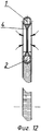
Фиг.12 - разрез проволочной намотки после обжатия.Fig - sectional view of wire winding after crimping.
Оправка для изготовления щеточного уплотнения содержит наружное 1 и внутреннее 2 кольца, размещенные в одной плоскости концентрично. Торообразную форму оправки придает модельная масса 3, заполняющая промежуток между кольцами 1, 2 и скрепляющая их между собой (фиг.1 и 2).The mandrel for the manufacture of brush seals contains an outer 1 and an inner 2 rings placed concentrically in the same plane. The toroidal shape of the mandrel gives
На фиг.3 и 4 изображена оправка с радиально намотанной проволокой 4. Проволока намотана плотно в несколько слоев. Оснастка для фиксации намотки проволоки 4 изображена в виде наружного хомута 5 (фиг.5) и разжимного кольца 6. Фиксирующие участки наружного хомута 5 и разжимного кольца 6 изображены на фиг.6 крупным планом и обозначены позициями 7 и 8 соответственно. На фиг.7 изображено выплавление модельной массы 3 из оправки в приемную емкость 9.Figures 3 and 4 show a mandrel with a radially
На фиг.8 изображено растворение модельной массы 3 из оправки в воде или органическом растворителе (поз.11) налитом в емкость 10.On Fig depicts the dissolution of the
На фиг.9 и 10 изображена закрутка витков проволоки на заданный угол βFigures 9 and 10 show the twist of the turns of wire at a given angle β
На фиг.11 и 12 изображена заключительная операция изготовления уплотнения - обжатие боковых участков щетины и резка.11 and 12 depict the final operation of the manufacture of the seal - compression of the lateral portions of the bristles and cutting.
Изготовление щеточного уплотнения осуществляют следующим образом. Вначале собирают горообразную оправку для намотки проволоки. Периметр профильного сечения оправки рассчитывают равным длине витка наматываемой проволоки в отклоненном на требуемый угол положении. В специальной форме для центробежного литья с периметром профиля сечения, равным периметру оправки, концентрично размещают кольца 1 и 2, центрируют их и фиксируют. Затем в промежуток между кольцами подают расплав специальной модельной массы 3 или мочевины и обеспечивают ее затвердевание. После чего заготовку оправки извлекают из формы, зачищают ее поверхность от облоя и контролируют профиль. После этого радиально виток к витку на оправку наматывают проволоку 4. По завершении намотки осуществляют контроль ее толщины и сплошности намотанных слоев. Затем производят фиксацию намотанной проволоки на кольцах 1 и 2 оправки. Для этого на кольцо 1 оправки размещают оснастку в виде наружного стяжного хомута 5 с профильной канавкой 7 (фиг.5 и 6), а на кольцо 2 оправки с его внутренней стороны - разжимное кольцо 6. В таком виде оснастку с оправкой помещают в сушильный шкаф для выплавления модельной массы. Если в качестве модельной массы используется мочевина или водорастворимый полимер то оснастку с оправкой помещают в ванночку с горячей водой, где мочевина растворяется.The manufacture of brush seals is as follows. First, a mountainous mandrel for winding wire is assembled. The perimeter of the cross-section of the mandrel is calculated equal to the length of the coil of the wound wire in a position deviated by the required angle. In a special form for centrifugal casting with a perimeter of the cross-sectional profile equal to the perimeter of the mandrel,
Для выплавления модельной массы 3 оснастку с оправкой помещают в сушильный шкаф, и модельная масса вытекает в приемную емкость. При этом проволочная намотка на оправке ослабевает и провисает вместе с разжимным кольцом 6 (фиг.8). Затем осуществляют поворот внутреннего кольца 2 оправки вместе с разжимным кольцом 6 относительно наружного 1 на угол соответственно требуемому углу наклона витков проволоки в изготовляемом щеточном уплотнении. При этом витки намотанной проволоки натягиваются. Далее проволочную намотку с кольцами 1 и 2 вставляют в гнездо узла статора двигателя и обжимают ее до требуемого размера (фиг.11). Свободные участки витков проволоки фиксируют и обрезают. Освобождающееся при этом внутреннее кольцо 2 оправки используют для изготовления следующего щеточного уплотнения. Наружное же кольцо 1 образует внешний каркас щеточного уплотнения и служит для фиксации проволочной щетины в узле статора двигателя.To smelting the
Способ изготовления щеточного уплотнения повышает эффективность работы уплотнительного узла в процессе его эксплуатации, поскольку позволяет получать намотку более высокой плотности, чему способствует ее виброобработка.A method of manufacturing a brush seal increases the efficiency of the sealing unit during its operation, since it allows to obtain a winding of a higher density, which contributes to its vibration processing.
Способ предусматривает изготовление уплотнений, интегрируемых в гнездо корпуса двигателя, минимизируя при этом количество деталей узла, что способствует снижению общего веса изделия. Кроме того, способ предусматривает обработку щеточного уплотнения под вал ротора непосредственно в собранном корпусном узле, что позволяет существенно снизить отклонение от соосности уплотнения и ротора при сборке двигателя. Способ исключает приварку проволоки к кольцу в качестве элемента крепления. При этом ее щетина не подвергается тепловому воздействию, что способствует увеличению срока службы щеточного уплотнения. Снижается вероятность отрыва отдельных щетинок от уплотнения, в месте заделки, с последующим попаданием их в ответственные трущиеся узлы, что позволяет использовать данную конструкцию для уплотнения масляных полостей.The method involves the manufacture of seals that are integrated into the socket of the engine housing, while minimizing the number of parts of the assembly, which helps to reduce the total weight of the product. In addition, the method provides for the processing of the brush seal under the rotor shaft directly in the assembled housing unit, which can significantly reduce the deviation from the alignment of the seal and the rotor during engine assembly. The method eliminates the welding of wire to the ring as an attachment element. At the same time, its bristles are not exposed to heat, which helps to increase the service life of the brush seal. Reduces the likelihood of separation of individual bristles from the seal, at the place of sealing, with their subsequent hit in the critical friction units, which allows you to use this design for sealing oil cavities.
Claims (5)
Priority Applications (1)
| Application Number | Priority Date | Filing Date | Title |
|---|---|---|---|
| RU2012118110/06A RU2485373C1 (en) | 2012-05-04 | 2012-05-04 | Manufacturing method of brush seal |
Applications Claiming Priority (1)
| Application Number | Priority Date | Filing Date | Title |
|---|---|---|---|
| RU2012118110/06A RU2485373C1 (en) | 2012-05-04 | 2012-05-04 | Manufacturing method of brush seal |
Publications (1)
| Publication Number | Publication Date |
|---|---|
| RU2485373C1 true RU2485373C1 (en) | 2013-06-20 |
Family
ID=48786395
Family Applications (1)
| Application Number | Title | Priority Date | Filing Date |
|---|---|---|---|
| RU2012118110/06A RU2485373C1 (en) | 2012-05-04 | 2012-05-04 | Manufacturing method of brush seal |
Country Status (1)
| Country | Link |
|---|---|
| RU (1) | RU2485373C1 (en) |
Citations (5)
| Publication number | Priority date | Publication date | Assignee | Title |
|---|---|---|---|---|
| US4934759A (en) * | 1988-04-05 | 1990-06-19 | Rolls-Royce Plc | Apparatus for and method of manufacturing brush seals |
| SU1756421A1 (en) * | 1990-07-11 | 1992-08-23 | Самарский филиал Научно-исследовательского института технологии и организации производства двигателей | Method of manufacturing brush sealing |
| RU2076256C1 (en) * | 1994-06-15 | 1997-03-27 | Научно-исследовательский институт технологии и организации производства двигателей | Manufacturing process for brush seals of gas-turbine engines |
| RU2210694C2 (en) * | 2001-10-01 | 2003-08-20 | Федеральное государственное унитарное предприятие "Центральный институт авиационного моторостроения" им. П.И.Баранова | Method of and device for manufacture of brush sealing |
| RU2289742C1 (en) * | 2005-05-24 | 2006-12-20 | Федеральное государственное унитарное предприятие "Московское машиностроительное производственное предприятие "САЛЮТ" (ФГУП "ММПП "САЛЮТ") | Method of producing brush seal |
-
2012
- 2012-05-04 RU RU2012118110/06A patent/RU2485373C1/en active
Patent Citations (5)
| Publication number | Priority date | Publication date | Assignee | Title |
|---|---|---|---|---|
| US4934759A (en) * | 1988-04-05 | 1990-06-19 | Rolls-Royce Plc | Apparatus for and method of manufacturing brush seals |
| SU1756421A1 (en) * | 1990-07-11 | 1992-08-23 | Самарский филиал Научно-исследовательского института технологии и организации производства двигателей | Method of manufacturing brush sealing |
| RU2076256C1 (en) * | 1994-06-15 | 1997-03-27 | Научно-исследовательский институт технологии и организации производства двигателей | Manufacturing process for brush seals of gas-turbine engines |
| RU2210694C2 (en) * | 2001-10-01 | 2003-08-20 | Федеральное государственное унитарное предприятие "Центральный институт авиационного моторостроения" им. П.И.Баранова | Method of and device for manufacture of brush sealing |
| RU2289742C1 (en) * | 2005-05-24 | 2006-12-20 | Федеральное государственное унитарное предприятие "Московское машиностроительное производственное предприятие "САЛЮТ" (ФГУП "ММПП "САЛЮТ") | Method of producing brush seal |
Similar Documents
| Publication | Publication Date | Title |
|---|---|---|
| EP3214275B1 (en) | Method of manufacturing two brush seals | |
| JP5997880B2 (en) | Electric machine rotor bar and manufacturing method thereof | |
| CN105431615B (en) | turbine engine casing and manufacturing method | |
| CN104904097B (en) | Cooling device for an electric motor and method for producing a hollow shaft therefor | |
| CN102241105A (en) | Method of manufacturing a rectifier | |
| CN105128324A (en) | Integral forming preparation method for carbon fiber tube with outwards-turning-edge flange | |
| CN105829650A (en) | Method for producing a stage of a steam turbine | |
| JP2010172189A (en) | Stator segment for stator of ring generator, stator device, stator of ring generator, and method of manufacturing stator segment for stator of ring generator | |
| US1470507A (en) | Method of making rotor elements for elastic-fluid turbines | |
| RU2015147866A (en) | METHOD FOR PRODUCING A ROTOR FOR A REACTIVE ELECTRIC MOTOR | |
| RU2485373C1 (en) | Manufacturing method of brush seal | |
| JP5609211B2 (en) | Rotating electric machine stator and method of manufacturing rotating electric machine stator | |
| EP3232537A1 (en) | Interior permanent magnet rotor hubs | |
| CN205792001U (en) | Motor | |
| US20160099624A1 (en) | End turn support and cooling fixture | |
| JP5405674B2 (en) | How to operate a reinforced fiber knitting machine | |
| WO2014126234A1 (en) | Turbine nozzle and method for manufacturing same | |
| RU2350811C1 (en) | Method of fabrication of brush sealing and device for implementation of this method | |
| JP2015532166A (en) | Brush manufacturing method and brush obtained by this method | |
| RU2003133996A (en) | STEAM TURBINE | |
| RU2289742C1 (en) | Method of producing brush seal | |
| RU2017107240A (en) | FOLDED CENTRIFUGA FOR THE PRODUCTION OF FIBER FROM MELTED MATERIAL | |
| EP2776188B1 (en) | Centrifugal casting apparatus and method | |
| US20150084285A1 (en) | Brush seal and method for producing a brush seal | |
| RU2661429C1 (en) | Method for manufacturing a guide blade device of an aircraft engine compressor |
Legal Events
| Date | Code | Title | Description |
|---|---|---|---|
| PC43 | Official registration of the transfer of the exclusive right without contract for inventions |
Effective date: 20151109 |
|
| PC43 | Official registration of the transfer of the exclusive right without contract for inventions |
Effective date: 20190802 |