RU2485207C2 - Method for masking of cooling holes, and device to be used during masking of cooling holes - Google Patents
Method for masking of cooling holes, and device to be used during masking of cooling holes Download PDFInfo
- Publication number
- RU2485207C2 RU2485207C2 RU2010104013/02A RU2010104013A RU2485207C2 RU 2485207 C2 RU2485207 C2 RU 2485207C2 RU 2010104013/02 A RU2010104013/02 A RU 2010104013/02A RU 2010104013 A RU2010104013 A RU 2010104013A RU 2485207 C2 RU2485207 C2 RU 2485207C2
- Authority
- RU
- Russia
- Prior art keywords
- component
- cooling holes
- coating
- turbine
- cover
- Prior art date
Links
Images

Classifications
-
- C—CHEMISTRY; METALLURGY
- C23—COATING METALLIC MATERIAL; COATING MATERIAL WITH METALLIC MATERIAL; CHEMICAL SURFACE TREATMENT; DIFFUSION TREATMENT OF METALLIC MATERIAL; COATING BY VACUUM EVAPORATION, BY SPUTTERING, BY ION IMPLANTATION OR BY CHEMICAL VAPOUR DEPOSITION, IN GENERAL; INHIBITING CORROSION OF METALLIC MATERIAL OR INCRUSTATION IN GENERAL
- C23C—COATING METALLIC MATERIAL; COATING MATERIAL WITH METALLIC MATERIAL; SURFACE TREATMENT OF METALLIC MATERIAL BY DIFFUSION INTO THE SURFACE, BY CHEMICAL CONVERSION OR SUBSTITUTION; COATING BY VACUUM EVAPORATION, BY SPUTTERING, BY ION IMPLANTATION OR BY CHEMICAL VAPOUR DEPOSITION, IN GENERAL
- C23C14/00—Coating by vacuum evaporation, by sputtering or by ion implantation of the coating forming material
- C23C14/04—Coating on selected surface areas, e.g. using masks
- C23C14/042—Coating on selected surface areas, e.g. using masks using masks
-
- C—CHEMISTRY; METALLURGY
- C23—COATING METALLIC MATERIAL; COATING MATERIAL WITH METALLIC MATERIAL; CHEMICAL SURFACE TREATMENT; DIFFUSION TREATMENT OF METALLIC MATERIAL; COATING BY VACUUM EVAPORATION, BY SPUTTERING, BY ION IMPLANTATION OR BY CHEMICAL VAPOUR DEPOSITION, IN GENERAL; INHIBITING CORROSION OF METALLIC MATERIAL OR INCRUSTATION IN GENERAL
- C23C—COATING METALLIC MATERIAL; COATING MATERIAL WITH METALLIC MATERIAL; SURFACE TREATMENT OF METALLIC MATERIAL BY DIFFUSION INTO THE SURFACE, BY CHEMICAL CONVERSION OR SUBSTITUTION; COATING BY VACUUM EVAPORATION, BY SPUTTERING, BY ION IMPLANTATION OR BY CHEMICAL VAPOUR DEPOSITION, IN GENERAL
- C23C4/00—Coating by spraying the coating material in the molten state, e.g. by flame, plasma or electric discharge
- C23C4/02—Pretreatment of the material to be coated, e.g. for coating on selected surface areas
-
- F—MECHANICAL ENGINEERING; LIGHTING; HEATING; WEAPONS; BLASTING
- F01—MACHINES OR ENGINES IN GENERAL; ENGINE PLANTS IN GENERAL; STEAM ENGINES
- F01D—NON-POSITIVE DISPLACEMENT MACHINES OR ENGINES, e.g. STEAM TURBINES
- F01D5/00—Blades; Blade-carrying members; Heating, heat-insulating, cooling or antivibration means on the blades or the members
- F01D5/12—Blades
- F01D5/28—Selecting particular materials; Particular measures relating thereto; Measures against erosion or corrosion
- F01D5/288—Protective coatings for blades
-
- F—MECHANICAL ENGINEERING; LIGHTING; HEATING; WEAPONS; BLASTING
- F05—INDEXING SCHEMES RELATING TO ENGINES OR PUMPS IN VARIOUS SUBCLASSES OF CLASSES F01-F04
- F05D—INDEXING SCHEME FOR ASPECTS RELATING TO NON-POSITIVE-DISPLACEMENT MACHINES OR ENGINES, GAS-TURBINES OR JET-PROPULSION PLANTS
- F05D2230/00—Manufacture
- F05D2230/30—Manufacture with deposition of material
- F05D2230/31—Layer deposition
- F05D2230/311—Layer deposition by torch or flame spraying
-
- F—MECHANICAL ENGINEERING; LIGHTING; HEATING; WEAPONS; BLASTING
- F05—INDEXING SCHEMES RELATING TO ENGINES OR PUMPS IN VARIOUS SUBCLASSES OF CLASSES F01-F04
- F05D—INDEXING SCHEME FOR ASPECTS RELATING TO NON-POSITIVE-DISPLACEMENT MACHINES OR ENGINES, GAS-TURBINES OR JET-PROPULSION PLANTS
- F05D2230/00—Manufacture
- F05D2230/30—Manufacture with deposition of material
- F05D2230/31—Layer deposition
- F05D2230/312—Layer deposition by plasma spraying
-
- F—MECHANICAL ENGINEERING; LIGHTING; HEATING; WEAPONS; BLASTING
- F05—INDEXING SCHEMES RELATING TO ENGINES OR PUMPS IN VARIOUS SUBCLASSES OF CLASSES F01-F04
- F05D—INDEXING SCHEME FOR ASPECTS RELATING TO NON-POSITIVE-DISPLACEMENT MACHINES OR ENGINES, GAS-TURBINES OR JET-PROPULSION PLANTS
- F05D2230/00—Manufacture
- F05D2230/90—Coating; Surface treatment
Landscapes
- Chemical & Material Sciences (AREA)
- Engineering & Computer Science (AREA)
- Materials Engineering (AREA)
- Mechanical Engineering (AREA)
- Chemical Kinetics & Catalysis (AREA)
- Metallurgy (AREA)
- Organic Chemistry (AREA)
- Physics & Mathematics (AREA)
- Plasma & Fusion (AREA)
- General Engineering & Computer Science (AREA)
- Turbine Rotor Nozzle Sealing (AREA)
- Manufacture Of Motors, Generators (AREA)
Abstract
Description
Настоящее изобретение относится к способу маскировки охладительных отверстий компонента турбины, такого как лопатка или лопасть турбины, для процесса покрытия. Далее, изобретение относится к способу покрытия наружной поверхности компонента турбины, такого как лопатка или лопасть турбины. Кроме того, изобретение относится к устройству для применения в процессе маскировки охладительных отверстий в компоненте турбины и/или для применения в процессе нанесения покрытия на такой компонент турбины. Компонент турбины может быть, в частности, компонентом газовой турбины, таким как лопатка или лопасть газовой турбины.The present invention relates to a method for masking cooling openings of a turbine component, such as a turbine blade or blade, for a coating process. The invention further relates to a method for coating the outer surface of a turbine component, such as a turbine blade or blade. In addition, the invention relates to a device for use in the process of masking cooling holes in a component of a turbine and / or for use in the coating process on such a component of a turbine. The turbine component may be, in particular, a gas turbine component, such as a blade or blade of a gas turbine.
Компоненты газовой турбины, которые подвергаются действию горячих газообразных продуктов сгорания, часто покрывают металлическими и/или керамическими покрытиями, чтобы улучшить их термостойкость и, тем самым, повысить их срок службы и улучшить рабочие характеристики. Примерами таких покрытий являются покрытия McrAlX, где M означает металл, в частности кобальт, никель или железо, X означает активный элемент, которым может быть, например, иттрий (Y) и/или кремний (Si), скандий (Sc) и/или по меньшей мере один редкоземельный элемент или гафний (Hf). Такие сплавы известны, например, из документов EP 0486489B1, EP 0786017B1, EP 0412397B1 или EP 1306454A1. На McrAlY-покрытие может наноситься теплоизолирующее покрытие (TBC). Такие теплоизолирующие покрытия типично выполняют из оксида циркония (ZrO2), кристаллическая структура которого может быть частично или полностью стабилизирована добавлением оксида иттрия (Y2O3).Gas turbine components that are exposed to hot gaseous combustion products are often coated with metal and / or ceramic coatings to improve their heat resistance and thereby increase their service life and improve performance. Examples of such coatings are McrAlX coatings, where M is a metal, in particular cobalt, nickel or iron, X is an active element, which may be, for example, yttrium (Y) and / or silicon (Si), scandium (Sc) and / or at least one rare earth element or hafnium (Hf). Such alloys are known, for example, from EP 0486489B1, EP 0786017B1, EP 0412397B1 or EP 1306454A1. A McrAlY coating may be coated with a thermal insulating coating (TBC). Such heat insulating coatings are typically made of zirconium oxide (ZrO 2 ), the crystal structure of which can be partially or fully stabilized by the addition of yttrium oxide (Y 2 O 3 ).
Кроме того, компоненты турбины, которые подвергаются действию горячих газообразных продуктов сгорания, часто имеют по меньшей мере одну внутреннюю полость и охладительные отверстия, идущие от внутренней полости наружу компонента. При работе такого компонента охлаждающая среда, например охлаждающий воздух, вылетает из охладительных отверстий, образуя пленку охлаждающей среды на поверхности компонента, чтобы защитить его от горячих газообразных продуктов сгорания.In addition, turbine components that are exposed to hot gaseous products of combustion often have at least one internal cavity and cooling openings extending from the internal cavity to the outside of the component. During operation of such a component, a cooling medium, for example cooling air, flies out of the cooling holes, forming a film of the cooling medium on the surface of the component in order to protect it from hot gaseous products of combustion.
Покрытия из металлического сплава или керамические покрытия обычно наносятся на поверхность компонента способами термического напыления, такими, например, как плазменное напыление при атмосферном давлении (APS) или высокоскоростным кислородно-топливным напылением (HVOF). Во всех случаях при нанесении покрытий может уменьшиться площадь сечения охладительных отверстий или они даже могут полностью забиться. Как следствие, эффективность течения охлаждающей среды через охладительные отверстия снижается. Таким образом, после нанесения покрытия частично или полностью забитые охладительные отверстия нужно снова открывать. Однако повторное раскрытие охладительных отверстий требует много времени и является сложным и, следовательно, затратным процессом. Кроме того, охладительные отверстия часто формируют электроэрозионной обработкой (EDM), которую нельзя применять после покрытия компонента электроизоляционным керамическим покрытием.Metal alloy coatings or ceramic coatings are typically applied to the surface of a component by thermal spraying methods, such as atmospheric pressure plasma spraying (APS) or high speed oxygen fuel spraying (HVOF). In all cases, when applying coatings, the cross-sectional area of the cooling holes may decrease, or they may even become completely clogged. As a result, the efficiency of the flow of the cooling medium through the cooling openings is reduced. Thus, after coating, partially or completely clogged cooling holes must be reopened. However, re-opening the cooling openings is time consuming and difficult and therefore expensive. In addition, cooling holes are often formed by EDM, which cannot be used after coating a component with an insulating ceramic coating.
Из-за упомянутых трудностей было предложено скрывать охладительные отверстия в процессе покрытия. Документ EP 1365039Al описывает способ маскировки охладительных отверстий компонента газовой турбины, в котором охладительные отверстия наполняются полимером как маскирующим материалом, который может быть отвержден с использованием ультрафиолетового излучения. Покрытие наносится после отверждения маскирующего материала. После нанесения покрытия оставшийся маскирующий материал в охладительных отверстиях может быть удален путем его выжигания. Документ DE 10 2006 029070B3 описывает способ покрытия компонента с охладительными отверстиями, в котором охладительные отверстия в процессе покрытия маскируются. Для нанесения покрытия на компонент используется пучок частиц. Маскирующий материал выбирают так, чтобы он уносился с пучком частиц.Due to the difficulties mentioned, it was proposed to hide the cooling holes in the coating process. EP 1365039Al describes a method for masking the cooling holes of a gas turbine component, in which the cooling holes are filled with polymer as a masking material that can be cured using ultraviolet radiation. The coating is applied after curing of the masking material. After coating, the remaining masking material in the cooling holes can be removed by burning it. DE 10 2006 029070B3 describes a method for coating a component with cooling holes, in which cooling holes are masked during the coating process. A particle beam is used to coat the component. The masking material is chosen so that it is carried away with a beam of particles.
Учитывая упомянутый предшествующий уровень техники, первой целью настоящего изобретения является дать выгодный способ маскировки охладительных отверстий компонента турбины. Второй целью настоящего изобретения является дать выгодный способ покрытия компонента турбины. Третьей целью настоящего изобретения является дать выгодное устройство для применения в процессе маскирования охладительных отверстий в компоненте турбины и/или в процессе покрытия компонента газовой турбины.Given the aforementioned prior art, the first objective of the present invention is to provide an advantageous method for masking the cooling holes of a turbine component. A second object of the present invention is to provide an advantageous method for coating a turbine component. A third object of the present invention is to provide an advantageous device for use in the process of masking cooling holes in a component of a turbine and / or in the process of coating a component of a gas turbine.
Первая цель достигнута способом маскировки охладительных отверстий компонента турбины согласно пункту 1 формулы изобретения. Вторая цель достигнута способом покрытия наружной поверхности компонента турбины согласно пункту 5, и третья цель достигнута устройством для применения в процессе маскирования охладительных отверстий в компоненте турбины и/или в процессе нанесения покрытия на компонент турбины согласно пункту 9. Зависимые пункты описывают дальнейшие усовершенствования изобретения.The first objective is achieved by a method of masking the cooling holes of a turbine component according to
Согласно изобретению дается способ маскировки охладительных отверстий компонента турбины для процесса покрытия. Компонент турбины содержит наружную поверхность, требующую покрытия, по меньшей мере одну внутреннюю полость, имеющую отверстие наружу компонента, и охладительные отверстия, идущие от этой по меньшей мере одной внутренней полости к наружной поверхности. Способ по изобретению включает в себя этапы заполнения охладительных отверстий маскирующим материалом и отверждения маскирующего материала. Согласно изобретению в качестве маскирующего материала в охладительные отверстия заливается вода. Таким образом, отверждение проводится, замораживая воду с получением льда.According to the invention, a method is provided for masking the cooling holes of a turbine component for a coating process. The turbine component comprises an outer surface requiring coating of at least one inner cavity having an opening to the outside of the component, and cooling holes extending from this at least one inner cavity to the outer surface. The method according to the invention includes the steps of filling the cooling openings with masking material and curing the masking material. According to the invention, water is poured into the cooling holes as a masking material. Thus, curing is carried out by freezing water to produce ice.
Использование водяного льда как маскирующего материала выгодно, так как вода является дешевым маскирующим материалом, который легко наносить и легко удалять. Кроме того, вода не представляет опасности для окружающей среды.The use of water ice as a masking material is advantageous since water is a cheap masking material that is easy to apply and easy to remove. In addition, water is not harmful to the environment.
Воду можно заливать в охладительные отверстия через отверстие по меньшей мере одной внутренней полости, тогда как охладительные отверстия герметично закрывают с наружной поверхности компонента. Благодаря этим мерам вода может легко втекать в охладительное отверстие, чтобы сравняться с наружной поверхностью, что приводит к гладкой покрываемой поверхности после того, как вода замерзнет в лед.Water can be poured into the cooling openings through the opening of at least one internal cavity, while the cooling openings are hermetically sealed from the outer surface of the component. Thanks to these measures, water can easily flow into the cooling hole to even out with the outer surface, which results in a smooth, coated surface after the water freezes into ice.
Замораживание воды может осуществляться путем отвода тепла от воды снаружи компонента. При отводе тепла снаружи компонента вода начинает замерзать от наружной поверхности компонента внутрь охладительных отверстий. Таким образом, замерзание можно контролировать, чтобы создать ледяную пробку желаемой толщины, внешняя сторона которой выровнена с наружной поверхностью. Однако по меньшей мере одна внутренняя полость также может быть по меньшей мере частично наполнена водой, которая замерзает во время процесса замораживания. Когда замерзшая вода находится также и во внутренней полости компонента, пробки в охладительных отверстиях наиболее устойчивы и в процессе покрытия не могут перемещаться внутрь внутренней полости.Water can be frozen by removing heat from the water outside the component. When heat is removed from the outside of the component, water begins to freeze from the outer surface of the component into the cooling holes. Thus, freezing can be controlled to create an ice plug of the desired thickness, the outer side of which is aligned with the outer surface. However, at least one internal cavity may also be at least partially filled with water, which freezes during the freezing process. When frozen water is also in the internal cavity of the component, the plugs in the cooling holes are most stable and cannot be moved inside the internal cavity during the coating process.
В способе по изобретению для покрытия наружной поверхности компонента турбины, который содержит наружную поверхность, требующую покрытия, по меньшей мере одну внутреннюю полость, открытую наружу компонента, и охладительные отверстия, идущие от этой по меньшей мере одной внутренней полости к наружной поверхности, охладительные отверстия маскируются согласно способу по изобретению маскировки охладительных отверстий. Затем на наружную поверхность наносится покрытие. При этом материал покрытия осаждается также на лед в охладительных отверстиях, образуя мостики покрытия, перекрывающие охладительные отверстия. После нанесения покрытия лед удаляют, плавя его и сливая расплавленный лед. Затем мостики покрытия удаляют, прикладывая импульс давления к охладительным отверстиям через по меньшей мере одну внутреннюю полость. Импульс давления затем вызывает расщепление мостиков покрытия. Таким образом, все охладительные отверстия могут опять открыть одновременно, просто вводя импульс давления в по меньшей мере одну внутреннюю полость, откуда он распространяется через охладительные отверстия к мостикам покрытия.In the method of the invention for coating the outer surface of a turbine component, which comprises an outer surface requiring coating of at least one inner cavity open to the outside of the component, and cooling holes extending from this at least one internal cavity to the outer surface, the cooling holes are masked according to the method of the invention masking the cooling holes. Then, a coating is applied to the outer surface. Moreover, the coating material is also deposited on ice in the cooling holes, forming coating bridges that overlap the cooling holes. After coating, the ice is removed by melting it and draining the molten ice. Then, the coating bridges are removed by applying a pressure impulse to the cooling holes through at least one internal cavity. The pressure pulse then causes splitting of the coating bridges. Thus, all cooling openings can again be opened simultaneously, simply by introducing a pressure impulse into at least one internal cavity, from where it propagates through the cooling openings to the coating bridges.
Импульс давления может быть приложен, используя жидкость, которую заливают во внутреннюю полость и охладительные отверстия. Так как жидкость является почти несжимаемой, импульс давления можно легко передать через жидкость без больших потерь. Альтернативно, импульс давления можно приложить, используя заполнение внутренней полости и охладительных отверстий газом. Хотя использование газа для распространения импульса давления означает более высокие потери из-за сжимаемости газа, применение газа выгодно тем, что после повторного открытия внутренней полости или охладительных отверстий в них не остается никаких остатков.A pressure pulse can be applied using a liquid that is poured into the internal cavity and cooling openings. Since the fluid is almost incompressible, a pressure pulse can be easily transmitted through the fluid without large losses. Alternatively, a pressure pulse may be applied by filling the internal cavity and cooling holes with gas. Although the use of gas to propagate a pressure pulse means higher losses due to the compressibility of the gas, the use of gas is advantageous in that there are no residues left after re-opening the internal cavity or cooling holes.
Плавлению льда после нанесения покрытия может помочь нагревание компонента, чтобы позволить более быстрое расплавление ледяных пробок и, тем самым, более высокую производительность в процессе покрытия.The melting of the ice after the coating can be helped by heating the component to allow faster melting of the ice plugs and thereby a higher productivity in the coating process.
Кроме того, изобретением дается устройство для применения в процессе маскировки для скрытия охладительных отверстий компонента турбины, в частности, для применения в отвечающем изобретению процессе маскировки охладительных отверстий и/или для применения в процессе покрытия компонента турбины, в частности, для применения в способе по изобретению для покрытия компонента турбины. Компонент турбины содержит наружную поверхность, требующую покрытия, по меньшей мере одну внутреннюю полость, открытую наружу компонента, и охладительные отверстия, идущие от этой по меньшей мере одной внутренней полости к наружной поверхности. Устройство по изобретению содержит опору для установки на нее компонента, уплотнение, крышку, охлаждающее устройство и напорную систему.In addition, the invention provides a device for use in the masking process to hide the cooling holes of a turbine component, in particular for use in the masking process of the cooling holes in accordance with the invention and / or for use in the coating process of a turbine component, in particular for use in the method of the invention to cover a turbine component. A turbine component comprises an outer surface requiring coating of at least one inner cavity, open to the outside of the component, and cooling holes extending from this at least one inner cavity to the outer surface. The device according to the invention contains a support for installing a component on it, a seal, a cover, a cooling device and a pressure system.
Опора может содержать, например, приспособление для вмещения хвостовика лопатки или лопасти турбины, которое позволяет установить компонент. Кроме того, опора содержит по меньшей мере один внутренний канал потока, который соединен или может быть соединен с водоснабжением и имеющий выходное отверстие. Он согласован с компонентом так, чтобы выходное отверстие канала потока гидродинамически сообщалось с отверстием во внутренней полости компонента, когда компонент установлен на опоре.The support may comprise, for example, a device for receiving the shank of a blade or turbine blade, which allows the component to be installed. In addition, the support contains at least one internal flow channel, which is connected or can be connected to the water supply and having an outlet. It is aligned with the component so that the outlet of the flow channel is hydrodynamically in communication with the hole in the internal cavity of the component when the component is mounted on a support.
Крышка имеет внутреннюю поверхность с уплотнительными поверхностями. Она выполнена так, чтобы подстраиваться под компонент, чтобы уплотнительные поверхности находились в местах, где в наружной поверхности имеются охладительные отверстия, и чтобы уплотнительные поверхности плотно лежали против наружной поверхности компонента, чтобы герметично перекрыть охладительные отверстия от утечки.The cover has an inner surface with sealing surfaces. It is designed to adapt to the component, so that the sealing surfaces are in places where there are cooling holes in the outer surface, and so that the sealing surfaces lie tightly against the outer surface of the component in order to seal the cooling holes from leakage.
Охлаждающее устройство служит для уменьшения температуры крышки по меньшей мере в области уплотнительных поверхностей до температуры, которая ниже температуры плавления водяного льда.The cooling device serves to reduce the temperature of the lid, at least in the area of the sealing surfaces, to a temperature which is lower than the melting temperature of water ice.
Напорная система соединена или может соединяться с опорой и подходит для введения импульса давления в среду во внутренний канал потока опоры. Затем импульс давления может распространяться через охладительные отверстия. Устройство по изобретению позволяет осуществить способ по изобретению и, таким образом, дает преимущества, которые уже были обсуждены в связи со способом по изобретению.The pressure system is connected or can be connected to the support and is suitable for introducing a pressure pulse into the medium into the internal flow channel of the support. The pressure pulse can then propagate through the cooling holes. The device according to the invention allows the implementation of the method according to the invention and, thus, provides the benefits that have already been discussed in connection with the method according to the invention.
Устройство по изобретению может, кроме того, содержать кронштейн, который может соединяться с опорой и имеет первый канал потока и второй канал потока, который идет от первого канала потока и имеет точку соединения с первым каналом потока, посредством чего он находится в гидродинамическом соединении с первым каналом потока. Первый канал потока имеет первый и второй клапан, причем первый клапан находится выше по потоку от точки соединения, а второй клапан ниже по потоку от точки соединения. Кроме того, первый канал потока может быть соединен с внутренним каналом потока опоры. Кроме того, первый канал потока соединен или может быть соединен с устройством подачи воды, а второй канал потока соединен или может быть соединен с напорной системой. В этом усовершенствовании устройства по изобретению, первый канал потока может использоваться для заполнения водой внутренней полости, а второй канал потока может использоваться для заполнения внутренней полости средой, которая будет переносить импульс давления. Используя первый клапан, можно защитить устройство подачи воды от импульса давления. Второй клапан служит для герметизации опоры от утечки воды из опоры и компонента после заполнения компонента водой.The device according to the invention may further comprise a bracket that can be connected to the support and has a first flow channel and a second flow channel that extends from the first flow channel and has a connection point to the first flow channel, whereby it is in fluid communication with the first flow channel. The first flow channel has a first and second valve, the first valve being upstream of the connection point and the second valve downstream of the connection point. In addition, the first flow channel may be connected to the internal flow channel of the support. In addition, the first flow channel is connected or can be connected to a water supply device, and the second flow channel is connected or can be connected to a pressure system. In this improvement of the device according to the invention, the first flow channel can be used to fill the internal cavity with water, and the second flow channel can be used to fill the internal cavity with the medium that will carry the pressure pulse. Using the first valve, you can protect the water supply device from a pressure pulse. The second valve serves to seal the support against leakage of water from the support and component after filling the component with water.
В следующем усовершенствовании устройства по изобретению крышка содержит по меньшей мере одну первую часть крышки и одну вторую часть крышки. Она содержит, кроме того, зажимное приспособление для прижима первой части крышки и второй части крышки друг к другу после помещения их на компонент. Реализация крышки как по меньшей мере одной первой части крышки и одной второй части крышки, которые могут зажиматься, упрощает монтаж и демонтаж крышки. Прижимая первую часть крышки и вторую часть крышки друг к другу, можно сделать так, чтобы крышка плотно прилегала к компоненту.In a further development of the device according to the invention, the lid comprises at least one first part of the lid and one second part of the lid. It also contains a clamping device for pressing the first part of the lid and the second part of the lid against each other after placing them on the component. The implementation of the cover as at least one first part of the cover and one second part of the cover, which can be clamped, simplifies the installation and dismantling of the cover. By pressing the first part of the lid and the second part of the lid against each other, it is possible to make the lid fit snugly against the component.
В следующем усовершенствовании устройства уплотнительные поверхности на внутренней поверхности крышки выполнены из эластичного материала, например резины.In a further development of the device, the sealing surfaces on the inner surface of the lid are made of an elastic material, for example rubber.
Охлаждающее устройство в устройстве по изобретению может быть выполнено как криогенная установка, которая подает криогенный агент. В этом случае крышка содержит внутренние охлаждающие каналы, соединенные или соединяемые с криогенной установкой для приема и проведения криогенного агента через крышку. Эта реализация устройства по изобретению дает простое средство для отведения тепла от наружной поверхности компонента турбины.The cooling device in the device according to the invention can be implemented as a cryogenic unit that supplies a cryogenic agent. In this case, the lid contains internal cooling channels connected or connected to the cryogenic installation for receiving and conducting the cryogenic agent through the lid. This implementation of the device according to the invention provides a simple means for removing heat from the outer surface of the turbine component.
Для ускорения процесса плавления льда в охладительных отверстиях после покрытия компонента устройство по изобретению может, кроме того, содержать нагреватель для нагревания компонента. Такой нагреватель может быть встроенным, прикрепленным или крепящимся к крышке и/или опоре. В простой реализации нагреватель может быть просто проволочным нагревательным элементом или нитью накала. Альтернативно, нагреватель может быть радиационным нагревателем.To accelerate the process of melting ice in the cooling holes after coating the component, the device according to the invention may further comprise a heater for heating the component. Such a heater may be built-in, attached or fastened to the lid and / or support. In a simple implementation, the heater may simply be a wire heating element or a filament. Alternatively, the heater may be a radiation heater.
Чтобы повысить безопасность при приложении импульса давления, устройство по изобретению может быть оборудовано удерживающим давление корпусом, который может быть установлен так, чтобы окружать устройство. Удерживающий давление корпус может быть, в частности, газонепроницаемым.To increase safety when applying a pressure pulse, the device according to the invention can be equipped with a pressure-holding housing that can be mounted so as to surround the device. The pressure holding housing may be, in particular, gas tight.
Во всех вариантах осуществления способа по изобретению и устройства по изобретению компонент турбины, который требуется покрыть, может быть компонентом газовой турбины, таким как лопасть или лопатка газовой турбины.In all embodiments of the method of the invention and the device of the invention, the turbine component to be coated may be a gas turbine component, such as a gas turbine blade or vane.
Дальнейшие отличительные признаки, свойства и преимущества настоящего изобретения станут ясными из следующего описания одного варианта осуществления изобретения в сочетании с приложенными чертежами. Отличительные признаки этого варианта осуществления могут быть выгодными как независимо от других признаков, так и в комбинации с другими признаками.Further features, features, and advantages of the present invention will become apparent from the following description of one embodiment of the invention in conjunction with the attached drawings. Distinctive features of this embodiment may be advantageous both independently of other features and in combination with other features.
Фиг.1 показывает устройство по изобретению во время процесса маскирования охладительных отверстий компонента турбины.Figure 1 shows the device according to the invention during the masking process of the cooling holes of a turbine component.
Фиг.2 схематически показывает компонент турбины во время процесса нанесения покрытия.2 schematically shows a turbine component during a coating process.
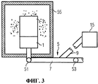
Фиг.3 показывает компонент турбины во время удаления мостиков покрытия.Figure 3 shows a component of a turbine during removal of coating bridges.
Теперь с обращением к фиг.1 будет описано устройство по изобретению для применения в процессе маскирования и/или покрытия компонента турбины. Устройство содержит зажимное приспособление 1, которое служит как опора, для удержания лопатки 3 турбины как компонента турбины, который требуется покрыть. Зажимное приспособление 1 может крепиться к кронштейну 5, который содержит первую трубу 7, образующую первый канал потока, и по меньшей мере одну вторую трубу 9, образующую второй канал потока. Вторая труба 9 соединена с первой трубой 7 в точке соединения 11 так, что эти каналы потоков находятся в гидродинамическом соединении друг с другом. Тогда как первая труба 7 ведет в устройство 13 подачи воды, вторая труба 9 ведет в напорную систему 15 устройства по изобретению.Now referring to FIG. 1, an apparatus of the invention for use in masking and / or coating a turbine component will be described. The device comprises a
Зажимное приспособление 1 содержит полость 17, которая выполнена так, чтобы принимать хвостовик 19 лопатки 3 турбины. Участок 4 несущей поверхности лопатки остается снаружи зажимного приспособления 1. Ее нижняя сторона граничит с контактной поверхностью 2 зажимного приспособления 1. Отметим, что нижняя сторона лопатки образована горизонтальным плоским участком, который для простоты на фигуре не показан. Резиновый уплотнитель 18 находится на контактной поверхности 2 зажимного приспособления 1 для уплотнения поверхности контакта, в которой зажимное приспособление 1 примыкает к лопатке 3 турбины. В настоящем варианте осуществления уплотнение 18 выполнено как резиновое уплотнительное кольцо, идущее вдоль края контактной поверхности 2 зажимного приспособления.The
Внутренняя полость 21 имеется в лопатке 3 турбины и хвостовике 19 лопатки, который имеет отверстие 23 наружу хвостовика 19 лопатки. Кроме того, охладительные отверстия 25 идут от внутренней полости 21 к наружной поверхности 27 лопатки 3 турбины. Когда лопатка 3 турбины работает в газовой турбине, охлаждающий воздух может вводиться во внутреннюю полость 21 через отверстие 23 в хвостовике 19 лопатки. Затем охлаждающий воздух покидает внутреннюю полость 21 через охладительные отверстия, образуя охлаждающую пленку на наружной поверхности 27 лопатки 3 турбины.The inner cavity 21 is present in the turbine blade 3 and the blade shaft 19, which has an opening 23 outside the blade shaft 19. In addition, the cooling holes 25 extend from the inner cavity 21 to the outer surface 27 of the turbine blade 3. When the turbine blade 3 is operated in a gas turbine, cooling air may be introduced into the internal cavity 21 through an opening 23 in the blade shaft 19. Then, the cooling air leaves the inner cavity 21 through the cooling holes, forming a cooling film on the outer surface 27 of the turbine blade 3.
Зажимное приспособление 1 содержит внутренний канал потока 29, который расположен так, чтобы выходное отверстие 30 внутреннего канала 29 потока находилось в гидродинамическом соединении с отверстием 23 хвостовика лопатки, вставленного в полость 17 зажимного приспособления, как это показано на фиг.1. Кроме того, первая труба 7 может быть соединена с внутренним каналом 29 потока зажимного приспособления 1. Фиг.1 показывает первую трубу, когда она соединена с внутренним каналом 29 потока.The
Устройство по изобретению содержит, кроме того, первую 31 часть крышки и вторую 33 часть крышки, которые могут быть помещены на лопатку 3 турбины, и зажимное приспособление 35 для прижима первой 31 части крышки и второй 33 части крышки друг к другу после помещения их на компонент 3, 19. Внутренние поверхности 37, 39 первой 31 части крышки и второй 33 части крышки содержат резиновые уплотнения 41, поверхности которых выровнены с или немного выходят за пределы внутренней поверхности 37, 39 соответствующей части 31, 33 крышки. Отметим, что вместо резиновых уплотнителей могут использоваться другие, предпочтительно эластичные, уплотнительные материалы для получения уплотнительных поверхностей во внутренних поверхностях 37, 39 частей крышки 31, 33. Уплотнительные поверхности, образованные резиновыми уплотнителями, в настоящем варианте осуществления расположены во внутренних поверхностях 37, 39 частей крышки 31, 33 так, чтобы они герметично закрывали охладительные отверстия 25 в наружной поверхность 27 лопатки 3 турбины от утечки, когда части крышки 31, 33 находятся на лопатке 3 турбины.The device according to the invention further comprises a first 31 part of the cap and a second 33 part of the cap, which can be placed on the turbine blade 3, and a clamping device 35 for pressing the first 31 part of the cap and the second 33 part of the cap to each other after placing them on the component 3, 19. The inner surfaces 37, 39 of the first 31 part of the lid and the second 33 of the part of the lid contain rubber seals 41 whose surfaces are aligned with or slightly outside the inner surface 37, 39 of the corresponding part 31, 33 of the lid. Note that instead of rubber seals, other, preferably elastic, sealing materials can be used to obtain sealing surfaces on the inner surfaces 37, 39 of the cover 31, 33. The sealing surfaces formed by the rubber seals in the present embodiment are located on the inner surfaces 37, 39 of the parts the covers 31, 33 so that they hermetically close the cooling holes 25 in the outer surface 27 of the turbine blade 3 from leakage when parts of the cover 31, 33 are on the blade tke 3 turbines.
Устройство по изобретению содержит, кроме того, охлаждающее устройство, которое в настоящем варианте осуществления выполнено как криогенная установка 43. Питающая линия 45 идет от криогенной установки 43, находящейся вне крышки 31, 33, и подает в охлаждающие каналы 49 внутри частей крышки 31, 33 криогенный агент, который может охлаждаться в криогенной установке 43. Далее, внутренние охлаждающие каналы 49 крышки 31, 33 соединены с обратной линией 47 криогенной установки 43 для подачи использованного криогенного агента снова в криогенную установку 43 для нового охлаждения. Температура криогенного агента, подаваемого в охлаждающие каналы 49 по питающей линии 45, устанавливается так, чтобы крышка 31, 33 охлаждалась ниже температуры плавления воды.The device according to the invention further comprises a cooling device, which in the present embodiment is configured as a cryogenic installation 43. The supply line 45 comes from a cryogenic installation 43 located outside the cover 31, 33, and delivers it to the cooling channels 49 inside the parts of the cover 31, 33 a cryogenic agent that can be cooled in the cryogenic unit 43. Further, the internal cooling channels 49 of the cover 31, 33 are connected to the return line 47 of the cryogenic unit 43 for supplying the used cryogenic agent again to the cryogenic unit 43 for n new cooling. The temperature of the cryogenic agent supplied to the cooling channels 49 through the supply line 45 is set so that the cover 31, 33 is cooled below the melting temperature of water.
Далее с обращением к фиг.1-3 будет описан способ по изобретению для покрытия наружной поверхности компонента турбины, который включает в себя также соответствующий изобретению способ маскировки охладительных отверстий компонента турбины. На этих фигурах лопатка газовой турбины будет служит примером компонента турбины, который требуется покрыть. Однако можно также маскировать и наносить покрытие в соответствии со способом по изобретению на другие компоненты турбины, как, например, лопасти турбины или элементы облицовки.Next, with reference to FIGS. 1-3, a method according to the invention for coating the outer surface of a turbine component will be described, which also includes a method of masking the cooling holes of a turbine component corresponding to the invention. In these figures, a gas turbine blade will be an example of a turbine component that needs to be coated. However, it is also possible to mask and coat in accordance with the method of the invention other components of the turbine, such as turbine blades or cladding elements.
На первом этапе лопатка 3 турбины, которую требуется покрыть, помещается своим хвостовиком 19 в полость 17 зажимного приспособления 1. Когда лопатка 3 турбины удерживается зажимным приспособлением 1, уплотнение 18 герметично закрывает любой возможно образовавшийся зазор между верхней стороной зажимного приспособления 1 на фиг.1 и нижней стороной участка 4 несущей поверхности лопатки. Зажимное приспособление 1 может уже быть соединено с кронштейном 5, когда лопатка 3 турбины закреплена на зажимном приспособлении 1. Однако можно также сначала закрепить лопатку 3 турбины на зажимном приспособлении 1 и затем прикрепить зажимное приспособление 1 вместе с присоединенной к нему лопаткой 3 турбины к кронштейну 5.At the first stage, the turbine blade 3 to be covered is placed with its shank 19 in the cavity 17 of the
Первую и вторую части крышки 31, 33 помещают на лопатку 3 турбины и прижимают друг к другу так, чтобы обе части крышки 31, 33 плотно прилегали к участку 4 несущей поверхности лопатки турбины. Когда части крышки 31, 33 садятся на лопатку 3 турбины, резиновые уплотнители 41 плотно лежат против охладительных отверстий 25.The first and second parts of the cover 31, 33 are placed on the turbine blade 3 and pressed against each other so that both parts of the cover 31, 33 fit snugly against the portion 4 of the bearing surface of the turbine blade. When the parts of the cover 31, 33 sit on the blade 3 of the turbine, the rubber seals 41 are tight against the cooling holes 25.
Когда зажимное приспособление 1 соединено с кронштейном 5, вода из устройства 13 подачи воды заполняет внутреннюю полость 21 лопатки турбины и охладительные отверстия 25 через первую трубу 7. Эта труба содержит два клапана, которые оба открыты, когда вода заливается во внутреннюю полость 21. После заполнения водой внутренней полости 21 охладительные отверстия 25 герметизируются резиновыми уплотнителями 41 в целях предотвращения утечки воды.When the
После того как внутренняя полость 21 и охладительные отверстия 25 наполнены водой, крышка 31, 33 охлаждается криогенным агентом, подводимым через охлаждающие каналы 49. Тем самым тепло от воды в охладительных отверстиях 25 отводится, так что вода замерзает (начиная от наружного отверстия охлаждающего отверстия и к внутренней полости 21). Процесс замораживания останавливается, когда ледяные пробки в охладительных отверстиях 25 достигнут желаемой толщины. При желании процесс охлаждения можно продолжить до тех пор, пока не замерзнет и вода во внутренней полости 21.After the inner cavity 21 and the cooling holes 25 are filled with water, the lid 31, 33 is cooled by a cryogenic agent supplied through the cooling channels 49. Thereby, heat from the water in the cooling holes 25 is removed, so that the water freezes (starting from the outer opening of the cooling hole and to the inner cavity 21). The freezing process stops when the ice plugs in the cooling holes 25 reach the desired thickness. If desired, the cooling process can be continued until the water in the inner cavity 21 freezes.
После образования ледяных пробок в охладительных отверстиях 25 части крышки 31, 33 удаляются с лопатки 3 турбины и зажимное приспособление 1, все еще удерживающее лопатку 3 турбины, демонтируется с кронштейна 5. Затем зажимное приспособление с лопаткой 3 турбины закрепляется на другом кронштейне 105, который является частью установки для нанесения покрытия (смотри фиг.2). В настоящем варианте осуществления установка для нанесения покрытия способна осуществлять процесс термического напыления, например газопламенное напыление, электродуговое напыление или плазменное напыление. Если используется установка газопламенного напыления, особенно хорошо подходит высокоскоростной аппарат кислородно-топливного напыления.After the formation of ice plugs in the cooling holes 25, the parts of the cover 31, 33 are removed from the turbine blade 3 and the
Помимо кронштейна 105 установка для нанесения покрытия содержит пульверизатор 107, ориентацию которого относительно лопатки 3 турбины можно менять. Изменений можно достичь, либо перемещая пульверизатор 107 относительно кронштейна 105, на котором закреплено зажимное приспособление 1 с лопаткой 3 турбины, либо перемещая кронштейн 105 относительно неподвижного пульверизатора 107, либо перемещая то и другое.In addition to the
В процессе напыления покрытие, например MCrAlX-покрытие и/или теплоизолирующее покрытие, наносится на наружную поверхность 27 участка 4 несущей поверхности лопатки турбины. В процессе покрытия ледяные пробки предотвращают попадание материала покрытия в охладительные отверстия 25. Когда процесс покрытия завершен, наружная поверхность лопатки турбины полностью закрыта материалом покрытия, за исключением хвостовика 19, который находится внутри зажимного приспособления 1 и изолирован от материала покрытия уплотнением 18, которое не допускает попадания материала покрытия из какого-либо зазора между зажимным приспособлением 1 и участком 4 несущей поверхности лопатки турбины.During the spraying process, a coating, for example an MCrAlX coating and / or a heat insulating coating, is applied to the outer surface 27 of the portion 4 of the bearing surface of the turbine blade. During the coating process, ice plugs prevent the coating material from entering the cooling holes 25. When the coating process is completed, the outer surface of the turbine blade is completely covered by the coating material, with the exception of the shank 19, which is located inside the
Чтобы гарантировать, что ледяные пробки в охладительных отверстиях 25 останутся до окончания процесса покрытия, температура криогенного агента выбирается достаточно низкой, чтобы заморозить воду намного ниже ее температуры плавления. Чем больше длится процесс покрытия, тем сильнее должны быть заморожены ледяные пробки.To ensure that the ice plugs in the cooling openings 25 remain until the end of the coating process, the temperature of the cryogenic agent is chosen low enough to freeze the water well below its melting point. The longer the coating process, the more ice plugs should be frozen.
После завершения процесса покрытия зажимное приспособление 1 с закрепленной на нем лопаткой 3 турбины демонтируется с кронштейна 105 установки для нанесения покрытия и снова закрепляется на кронштейне 5 устройства по изобретению. Затем лопатке 3 турбины позволяют снова нагреться, чтобы ледяные пробки в охладительных отверстиях 25 и, если применимо, во внутренней полости 21 растаяли и стекли. Процесс нагрева можно факультативно облегчить нагревателем, которым может быть, например, нить накала, обмотанная вокруг лопатки 3 турбины, или радиационный нагреватель. Однако можно просто подождать, пока весь лед не растает.After completing the coating process, the
Для спуска воды открывают клапан 51 в первой трубе 7. В таком случае вода может отводиться по дополнительному ответвлению трубы (не показано) или также через открывание клапана 53 и проведение спускаемой воды в устройство 13 подачи воды. После того как ледяные пробки растаяли, покрытие, нанесенное на поверхность поверх охладительных отверстий 25, теряет свою заднюю опору.To drain the water, open the
Когда вода спущена, зажимное приспособление 1 с покрытой лопаткой 3 турбины помещают в удерживающий давление газонепроницаемый корпус 55 (смотри фиг.3) для удаления мостиков покрытия, распложенных над охладительными отверстиями 25. Затем внутреннюю полость 21 и охладительные отверстия 25 лопатки 3 турбины наполняют газом или жидкостью через трубу 7 и ответвительную трубу 9. Далее с помощью напорной системы 15 прикладывают импульс давления, который распространяется через газ или жидкость во внутреннюю полость 21 к охладительным отверстиям 25 и к мостикам покрытия, перекрывающим охладительные отверстия 25. Ударная волна импульса давления заставляет мостики покрытия отщепляться от выходов охладительных отверстий 25.When the water is drained, the
Выбор газа или жидкости, состава газа, уровня давления и параметров давления во времени решает, насколько эффективно можно удалить поверхностное покрытие с выходов охладительных отверстий 25. Например, несжимаемость жидкости приводит к эффективному распространению импульса давления через такую среду. С другой стороны, газ, который используется для передачи импульса давления, не нужно выпускать из внутренней части лопатки 3 турбины, и он может даже выбрасывать воду, которая остается в лопатке 3 турбины.The choice of gas or liquid, gas composition, pressure level and pressure parameters over time determines how efficiently the surface coating can be removed from the exits of the cooling holes 25. For example, the incompressibility of a liquid leads to the effective propagation of a pressure pulse through such a medium. On the other hand, the gas that is used to transmit the pressure pulse does not need to be discharged from the inside of the turbine blade 3, and it can even eject water that remains in the turbine blade 3.
Когда импульс давления прикладывается после того, как лопатка 3 турбины наполнена средой, передающей импульс давления, клапан 53 первой трубы 7 закрывается, чтобы защитить устройство 13 подачи воды от импульса давления.When a pressure pulse is applied after the turbine blade 3 is filled with a medium transmitting the pressure pulse, the
Способ по изобретению и устройство по изобретению позволяют временно и экологически безопасно закрывать охладительные отверстия компонента турбины для защиты их в процессе покрытия поверхности. Для повторного открытия охладительных отверстий не требуется, чтобы охладительные отверстия открывались по одному. Напротив, все охладительные отверстия могут быть снова открыты одновременно посредством импульса давления.The method according to the invention and the device according to the invention allow temporarily and environmentally safe to close the cooling holes of the turbine component to protect them during surface coating. The re-opening of the cooling holes does not require that the cooling holes open one at a time. On the contrary, all cooling openings can be re-opened simultaneously by means of a pressure pulse.
Claims (16)
заполняют охладительные отверстия (25) маскирующим материалом;
отверждают маскирующий материал,
отличающийся тем, что в качестве маскирующего материала охладительные отверстия (25) заполняют водой, а отверждение осуществляется путем замораживания воды в лед.1. The method of masking the cooling holes (25) of the component (3) of the turbine, in particular the blades or blades of the turbine, for the coating process, moreover, component (3) contains the outer surface (27), which you want to cover at least one internal cavity (21 ) having an opening (23) to the outside of the component (3), and cooling holes (25) extending from at least one inner cavity (21) to the outer surface (27), the method comprising the steps of:
fill the cooling holes (25) with masking material;
curing masking material
characterized in that, as a masking material, the cooling holes (25) are filled with water, and curing is carried out by freezing water in ice.
маскируют охладительные отверстия (25) способом по любому из пп.1-4;
наносят покрытие на наружную поверхность (27), тем самым осаждая материал покрытия на лед в охладительных отверстиях (25) с образованием мостиков покрытия, соединяющих охладительные отверстия (25);
удаляют лед после нанесения покрытия путем его расплавления и слива расплавленного льда;
удаляют мостики покрытия, прикладывая импульс давления к охладительным отверстиям (25) через по меньшей мере одну внутреннюю полость(21).5. A method of coating the outer surface (27) of a component (3) of a turbine, in particular a turbine blade and blade, the component (3) comprising an outer surface (27) that needs to be coated with at least one internal cavity (21) having an opening (23) the outward component (3), and cooling holes (25) extending from at least one inner cavity (21) to the outer surface (27), the method comprising the steps of:
masking the cooling holes (25) by the method according to any one of claims 1 to 4;
coating the outer surface (27), thereby depositing the coating material on ice in the cooling holes (25) to form coating bridges connecting the cooling holes (25);
ice is removed after coating by melting it and draining the molten ice;
remove the coating bridges by applying a pressure pulse to the cooling holes (25) through at least one internal cavity (21).
опору (1) для установки на нее компонента (3), содержащую по меньшей мере один внутренний канал (29) потока, который соединен или выполнен с возможностью соединения с устройством (13) подачи воды и имеет выходное отверстие (30), при этом опора (1) согласована с компонентом (3) так, что выходное отверстие (30) канала (29) потока сообщается по текучей среде с отверстием (23) внутренней полости (21) при установке компонента (3) на опору (1),
крышку (31, 33) с внутренней поверхностью (37, 39), которая имеет уплотнительные поверхности (41), причем крышка (31, 33) выполнена с возможностью установки на компонент (3) так, что уплотнительные поверхности (41) находятся в местах, в которых в наружной поверхности (27) расположены охладительные отверстия (25), и так, что уплотнительные поверхности (41) плотно прилегают к наружной поверхности (27) компонента (3) для уплотнения охладительных отверстий (25) от утечки;
охлаждающее устройство (43, 45, 47, 49) для уменьшения температуры крышки (31, 33) по меньшей мере в области уплотнительных поверхностей (41) до температуры, которая ниже температуры плавления льда; и
напорную систему (15), соединенную или соединяемую с опорой (1) для введения импульса давления в текучую среду во внутреннем канале (29) потока опоры (1).9. Device for masking the cooling holes (25) in the turbine component (3) during the masking of the cooling holes in the turbine component (3), in particular turbine blades or blades, in particular for use in the method according to any one of claims 1 to 4 and / or in the process of coating a component (3) of a turbine, in particular for use in the method according to any one of claims 5 to 8, wherein component (3) comprises an outer surface (27) that needs to be coated at least one internal cavity (21) having an opening (23) to the outside of the component (3), and cool solid holes (25) extending from this at least one inner cavity (21) to the outer surface (27), the device comprising:
a support (1) for installing a component (3) on it, containing at least one internal flow channel (29), which is connected or configured to connect to a water supply device (13) and has an outlet (30), while the support (1) matched with component (3) so that the outlet (30) of the flow channel (29) is in fluid communication with the hole (23) of the internal cavity (21) when component (3) is mounted on the support (1),
a cover (31, 33) with an inner surface (37, 39) that has sealing surfaces (41), and the cover (31, 33) is configured to be mounted on the component (3) so that the sealing surfaces (41) are in places in which cooling holes (25) are located in the outer surface (27), and so that the sealing surfaces (41) fit snugly against the outer surface (27) of the component (3) to seal the cooling holes (25) against leakage;
a cooling device (43, 45, 47, 49) for reducing the temperature of the lid (31, 33) at least in the area of the sealing surfaces (41) to a temperature that is lower than the melting temperature of the ice; and
a pressure system (15) connected or connected to a support (1) for introducing a pressure pulse into the fluid in the internal channel (29) of the flow of the support (1).
причем первый канал (7) потока выполнен с возможностью соединения с внутренним каналом (29) потока опоры (1) и с устройством (13) подачи воды; а второй канал (9) потока соединен или выполнен с возможностью соединения с напорной системой (15).10. The device according to claim 9, further comprising a bracket (5) configured to connect to a support (1) and comprising a first flow channel (7) and a second flow channel (9) that extends from the first flow channel (7) and has a connection point (11) with the first flow channel (7) through which it is in fluid communication with the first flow channel (7), the first flow channel (7) containing the first and second valves (51, 53), while the first the valve (53) is upstream of the connection point (11), and the second valve (51) is downstream of the connection point (11);
moreover, the first flow channel (7) is configured to connect to the internal channel (29) of the support stream (1) and to the water supply device (13); and the second flow channel (9) is connected or configured to connect to a pressure system (15).
Applications Claiming Priority (3)
| Application Number | Priority Date | Filing Date | Title |
|---|---|---|---|
| EP08004817.6 | 2008-03-14 | ||
| EP08004817A EP2100984A1 (en) | 2008-03-14 | 2008-03-14 | Method for masking cooling holes and device for using in a masking process for masking cooling holes |
| PCT/EP2009/051956 WO2009112333A1 (en) | 2008-03-14 | 2009-02-19 | Method for masking cooling holes and device for using in a masking process for masking cooling holes |
Publications (2)
| Publication Number | Publication Date |
|---|---|
| RU2010104013A RU2010104013A (en) | 2011-08-10 |
| RU2485207C2 true RU2485207C2 (en) | 2013-06-20 |
Family
ID=39598408
Family Applications (1)
| Application Number | Title | Priority Date | Filing Date |
|---|---|---|---|
| RU2010104013/02A RU2485207C2 (en) | 2008-03-14 | 2009-02-19 | Method for masking of cooling holes, and device to be used during masking of cooling holes |
Country Status (7)
| Country | Link |
|---|---|
| US (1) | US8021719B2 (en) |
| EP (2) | EP2100984A1 (en) |
| CN (1) | CN101772587B (en) |
| AT (1) | ATE498705T1 (en) |
| DE (1) | DE602009000741D1 (en) |
| RU (1) | RU2485207C2 (en) |
| WO (1) | WO2009112333A1 (en) |
Cited By (1)
| Publication number | Priority date | Publication date | Assignee | Title |
|---|---|---|---|---|
| RU2566409C1 (en) * | 2014-07-03 | 2015-10-27 | Акционерное общество "Обнинское научно-производственное предприятие "Технология" им. А.Г. Ромашина" (АО "ОНПП "Технология" им.А.Г.Ромашина") | Isolation of bores in metal parts at painting |
Families Citing this family (14)
| Publication number | Priority date | Publication date | Assignee | Title |
|---|---|---|---|---|
| US8528208B2 (en) * | 2011-04-11 | 2013-09-10 | General Electric Company | Methods of fabricating a coated component using multiple types of fillers |
| US8887662B2 (en) | 2011-12-29 | 2014-11-18 | General Electric Company | Pressure masking systems and methods for using the same |
| US8985049B2 (en) | 2011-12-29 | 2015-03-24 | General Electric Company | Pressure maskers and pressure masking systems |
| US9518317B2 (en) | 2012-05-11 | 2016-12-13 | General Electric Company | Method of coating a component, method of forming cooling holes and a water soluble aperture plug |
| US8974859B2 (en) | 2012-09-26 | 2015-03-10 | General Electric Company | Micro-channel coating deposition system and method for using the same |
| US10775115B2 (en) * | 2013-08-29 | 2020-09-15 | General Electric Company | Thermal spray coating method and thermal spray coated article |
| US10309002B2 (en) | 2013-12-05 | 2019-06-04 | General Electric Company | Coating methods and a template for use with the coating methods |
| EP3029176A1 (en) * | 2014-12-02 | 2016-06-08 | Siemens Aktiengesellschaft | Long, continuous engraving along a row of cooling holes |
| JP6235449B2 (en) | 2014-12-03 | 2017-11-22 | 三菱日立パワーシステムズ株式会社 | Thermal spray coating method, turbine high-temperature component, turbine, thermal spray coating masking pin, and masking member |
| US9845703B2 (en) * | 2014-12-12 | 2017-12-19 | General Electric Company | Turbine component surface treatment processes and systems |
| WO2018057414A1 (en) | 2016-09-23 | 2018-03-29 | General Electric Company | Method of coating an article, paste and plug for preventing hole blockage during coating |
| CN105970139B (en) * | 2016-07-12 | 2018-04-24 | 华能国际电力股份有限公司 | Hole sealing device and method are titrated in a kind of thermal spray process micropore |
| US20190194799A1 (en) * | 2017-12-22 | 2019-06-27 | United Technologies Corporation | Line-of-sight coating fixture and apparatus |
| CN114473481B (en) * | 2021-12-22 | 2023-07-07 | 湖北三江航天红峰控制有限公司 | O-shaped ring mounting process penetrating through intersecting holes |
Citations (3)
| Publication number | Priority date | Publication date | Assignee | Title |
|---|---|---|---|---|
| RU94033247A (en) * | 1994-09-08 | 1996-07-20 | А.П. Карабанов | Method and device for sand-blasting treatment |
| EP1365039A1 (en) * | 2002-05-24 | 2003-11-26 | ALSTOM (Switzerland) Ltd | Process of masking colling holes of a gas turbine component |
| DE102006029070B3 (en) * | 2006-06-16 | 2007-08-23 | Siemens Ag | Process to apply a protective coating to gas turbine engine blade with hole sidewalls masked by sacrificial plug |
Family Cites Families (8)
| Publication number | Priority date | Publication date | Assignee | Title |
|---|---|---|---|---|
| US2775101A (en) | 1952-11-07 | 1956-12-25 | Carrier Corp | Self-contained ice making unit |
| DE3926479A1 (en) | 1989-08-10 | 1991-02-14 | Siemens Ag | RHENIUM-PROTECTIVE COATING, WITH GREAT CORROSION AND / OR OXIDATION RESISTANCE |
| JP2773050B2 (en) | 1989-08-10 | 1998-07-09 | シーメンス アクチエンゲゼルシヤフト | Heat-resistant and corrosion-resistant protective coating layer |
| DE4318663C1 (en) * | 1993-06-04 | 1994-10-13 | Siemens Solar Gmbh | Method for masking and treating a surface of a substrate |
| RU2147624C1 (en) | 1994-10-14 | 2000-04-20 | Сименс АГ | Protective layer for protecting part against corrosion, oxidation, and thermal overloading, and method of preparation thereof |
| EP1306454B1 (en) | 2001-10-24 | 2004-10-06 | Siemens Aktiengesellschaft | Rhenium containing protective coating protecting a product against corrosion and oxidation at high temperatures |
| US7435353B2 (en) * | 2004-12-09 | 2008-10-14 | President And Fellows Of Harvard College | Patterning by energetically-stimulated local removal of solid-condensed-gas layers and solid state chemical reactions produced with such layers |
| US20060125144A1 (en) * | 2004-12-14 | 2006-06-15 | Jan Weber | Stent and stent manufacturing methods |
-
2008
- 2008-03-14 EP EP08004817A patent/EP2100984A1/en not_active Withdrawn
-
2009
- 2009-02-19 RU RU2010104013/02A patent/RU2485207C2/en not_active IP Right Cessation
- 2009-02-19 CN CN200980100081XA patent/CN101772587B/en not_active Expired - Fee Related
- 2009-02-19 WO PCT/EP2009/051956 patent/WO2009112333A1/en active Application Filing
- 2009-02-19 US US12/672,426 patent/US8021719B2/en not_active Expired - Fee Related
- 2009-02-19 DE DE602009000741T patent/DE602009000741D1/en active Active
- 2009-02-19 EP EP09720911A patent/EP2167699B1/en not_active Not-in-force
- 2009-02-19 AT AT09720911T patent/ATE498705T1/en not_active IP Right Cessation
Patent Citations (3)
| Publication number | Priority date | Publication date | Assignee | Title |
|---|---|---|---|---|
| RU94033247A (en) * | 1994-09-08 | 1996-07-20 | А.П. Карабанов | Method and device for sand-blasting treatment |
| EP1365039A1 (en) * | 2002-05-24 | 2003-11-26 | ALSTOM (Switzerland) Ltd | Process of masking colling holes of a gas turbine component |
| DE102006029070B3 (en) * | 2006-06-16 | 2007-08-23 | Siemens Ag | Process to apply a protective coating to gas turbine engine blade with hole sidewalls masked by sacrificial plug |
Cited By (1)
| Publication number | Priority date | Publication date | Assignee | Title |
|---|---|---|---|---|
| RU2566409C1 (en) * | 2014-07-03 | 2015-10-27 | Акционерное общество "Обнинское научно-производственное предприятие "Технология" им. А.Г. Ромашина" (АО "ОНПП "Технология" им.А.Г.Ромашина") | Isolation of bores in metal parts at painting |
Also Published As
| Publication number | Publication date |
|---|---|
| ATE498705T1 (en) | 2011-03-15 |
| EP2100984A1 (en) | 2009-09-16 |
| CN101772587A (en) | 2010-07-07 |
| DE602009000741D1 (en) | 2011-03-31 |
| US8021719B2 (en) | 2011-09-20 |
| EP2167699B1 (en) | 2011-02-16 |
| EP2167699A1 (en) | 2010-03-31 |
| CN101772587B (en) | 2012-05-30 |
| US20110086169A1 (en) | 2011-04-14 |
| WO2009112333A1 (en) | 2009-09-17 |
| RU2010104013A (en) | 2011-08-10 |
Similar Documents
| Publication | Publication Date | Title |
|---|---|---|
| RU2485207C2 (en) | Method for masking of cooling holes, and device to be used during masking of cooling holes | |
| CA2268402C (en) | A method of reducing the gap between a liner and a turbine distributor of a turbojet engine | |
| EP1391537A1 (en) | Coating forming method and coating forming material, and abrasive coating forming sheet | |
| FR2521213A1 (en) | TURBINE MOBILE DRAFT FOR GAS FLOW MACHINES, IN PARTICULAR FOR GAS TURBINE DRIVE MECHANISMS | |
| EP2935951B1 (en) | Closure of cooling holes with a filling agent | |
| EP2082119B1 (en) | Valve seat insert for a piston engine | |
| FR2644088A1 (en) | METHOD FOR MANUFACTURING FOUNDRY ELBOW | |
| AU4095197A (en) | Plating turbine engine components | |
| EP1743951B1 (en) | Microplasma deposition methods | |
| EP2935836B1 (en) | Closure of cooling holes with a filling agent | |
| JP2012082518A (en) | Thermal spray method not requiring control of cooling air hole | |
| JP2006189046A (en) | Cooling slot protective device, protective shield and method of coating component | |
| JP2007138941A (en) | Coating device and method of turbine engine component | |
| JP2010065690A (en) | Turbine bucket with dovetail seal and related method | |
| CA2385932C (en) | Turbine blade, manufacturing method of turbine blade, and strip judging method of thermal barrier coat | |
| US6145470A (en) | Apparatus for electron beam physical vapor deposition | |
| US11319257B2 (en) | Ceramic heat shields having surface infiltration for preventing corrosion and erosion attacks | |
| KR100901112B1 (en) | Method for providing a component of a large machine with a protective coating | |
| KR20190008087A (en) | Aluminum foam core piston with coaxial laser bonded aerogel/ceramic head | |
| US11022039B2 (en) | Method of manufacturing conductive film holes | |
| JP3954728B2 (en) | Refractory molded body for gas blowing | |
| EP1652955B1 (en) | Method for repairing thermal barrier coatings | |
| BE1004462A3 (en) | Process for painting engine. | |
| EP0084785B1 (en) | Quenching metal or an alloy on a belt | |
| FR2868434A1 (en) | METHODS FOR COATING A SUBSTRATE AND FORMING COLOR FILM AND DEVICE THEREFOR |
Legal Events
| Date | Code | Title | Description |
|---|---|---|---|
| MM4A | The patent is invalid due to non-payment of fees |
Effective date: 20160220 |