RU2483471C2 - Transmitter with relative time timer - Google Patents
Transmitter with relative time timer Download PDFInfo
- Publication number
- RU2483471C2 RU2483471C2 RU2011123747/07A RU2011123747A RU2483471C2 RU 2483471 C2 RU2483471 C2 RU 2483471C2 RU 2011123747/07 A RU2011123747/07 A RU 2011123747/07A RU 2011123747 A RU2011123747 A RU 2011123747A RU 2483471 C2 RU2483471 C2 RU 2483471C2
- Authority
- RU
- Russia
- Prior art keywords
- time
- data
- transmitter
- relative
- real
- Prior art date
Links
Images
Classifications
-
- H—ELECTRICITY
- H04—ELECTRIC COMMUNICATION TECHNIQUE
- H04B—TRANSMISSION
- H04B1/00—Details of transmission systems, not covered by a single one of groups H04B3/00 - H04B13/00; Details of transmission systems not characterised by the medium used for transmission
- H04B1/02—Transmitters
-
- H—ELECTRICITY
- H04—ELECTRIC COMMUNICATION TECHNIQUE
- H04Q—SELECTING
- H04Q9/00—Arrangements in telecontrol or telemetry systems for selectively calling a substation from a main station, in which substation desired apparatus is selected for applying a control signal thereto or for obtaining measured values therefrom
- H04Q9/04—Arrangements for synchronous operation
-
- G—PHYSICS
- G04—HOROLOGY
- G04F—TIME-INTERVAL MEASURING
- G04F1/00—Apparatus which can be set and started to measure-off predetermined or adjustably-fixed time intervals without driving mechanisms, e.g. egg timers
- G04F1/005—Apparatus which can be set and started to measure-off predetermined or adjustably-fixed time intervals without driving mechanisms, e.g. egg timers using electronic timing, e.g. counting means
-
- G—PHYSICS
- G04—HOROLOGY
- G04G—ELECTRONIC TIME-PIECES
- G04G5/00—Setting, i.e. correcting or changing, the time-indication
-
- G—PHYSICS
- G05—CONTROLLING; REGULATING
- G05B—CONTROL OR REGULATING SYSTEMS IN GENERAL; FUNCTIONAL ELEMENTS OF SUCH SYSTEMS; MONITORING OR TESTING ARRANGEMENTS FOR SUCH SYSTEMS OR ELEMENTS
- G05B19/00—Programme-control systems
- G05B19/02—Programme-control systems electric
- G05B19/18—Numerical control [NC], i.e. automatically operating machines, in particular machine tools, e.g. in a manufacturing environment, so as to execute positioning, movement or co-ordinated operations by means of programme data in numerical form
- G05B19/408—Numerical control [NC], i.e. automatically operating machines, in particular machine tools, e.g. in a manufacturing environment, so as to execute positioning, movement or co-ordinated operations by means of programme data in numerical form characterised by data handling or data format, e.g. reading, buffering or conversion of data
-
- G—PHYSICS
- G05—CONTROLLING; REGULATING
- G05B—CONTROL OR REGULATING SYSTEMS IN GENERAL; FUNCTIONAL ELEMENTS OF SUCH SYSTEMS; MONITORING OR TESTING ARRANGEMENTS FOR SUCH SYSTEMS OR ELEMENTS
- G05B23/00—Testing or monitoring of control systems or parts thereof
- G05B23/02—Electric testing or monitoring
-
- G—PHYSICS
- G05—CONTROLLING; REGULATING
- G05D—SYSTEMS FOR CONTROLLING OR REGULATING NON-ELECTRIC VARIABLES
- G05D7/00—Control of flow
- G05D7/06—Control of flow characterised by the use of electric means
-
- G—PHYSICS
- G08—SIGNALLING
- G08C—TRANSMISSION SYSTEMS FOR MEASURED VALUES, CONTROL OR SIMILAR SIGNALS
- G08C17/00—Arrangements for transmitting signals characterised by the use of a wireless electrical link
- G08C17/02—Arrangements for transmitting signals characterised by the use of a wireless electrical link using a radio link
-
- G—PHYSICS
- G05—CONTROLLING; REGULATING
- G05B—CONTROL OR REGULATING SYSTEMS IN GENERAL; FUNCTIONAL ELEMENTS OF SUCH SYSTEMS; MONITORING OR TESTING ARRANGEMENTS FOR SUCH SYSTEMS OR ELEMENTS
- G05B2219/00—Program-control systems
- G05B2219/30—Nc systems
- G05B2219/31—From computer integrated manufacturing till monitoring
- G05B2219/31126—Transmitter coupled to fieldbus and to sensor, a-d conversion
-
- G—PHYSICS
- G05—CONTROLLING; REGULATING
- G05B—CONTROL OR REGULATING SYSTEMS IN GENERAL; FUNCTIONAL ELEMENTS OF SUCH SYSTEMS; MONITORING OR TESTING ARRANGEMENTS FOR SUCH SYSTEMS OR ELEMENTS
- G05B2219/00—Program-control systems
- G05B2219/30—Nc systems
- G05B2219/34—Director, elements to supervisory
- G05B2219/34413—Add time stamp to command message
-
- H—ELECTRICITY
- H04—ELECTRIC COMMUNICATION TECHNIQUE
- H04Q—SELECTING
- H04Q9/00—Arrangements in telecontrol or telemetry systems for selectively calling a substation from a main station, in which substation desired apparatus is selected for applying a control signal thereto or for obtaining measured values therefrom
Landscapes
- Engineering & Computer Science (AREA)
- General Physics & Mathematics (AREA)
- Physics & Mathematics (AREA)
- Automation & Control Theory (AREA)
- Computer Networks & Wireless Communication (AREA)
- Manufacturing & Machinery (AREA)
- Human Computer Interaction (AREA)
- Signal Processing (AREA)
- Arrangements For Transmission Of Measured Signals (AREA)
- Selective Calling Equipment (AREA)
- Radar Systems Or Details Thereof (AREA)
- Communication Control (AREA)
- Transceivers (AREA)
- Electric Clocks (AREA)
Abstract
Description
Область техники, к которой относится изобретениеFIELD OF THE INVENTION
Настоящее изобретение относится к передатчикам данных и более конкретно к передатчикам данных, имеющим таймер относительного времени для генерирования временных меток относительного времени для передаваемых данных.The present invention relates to data transmitters and more particularly to data transmitters having a relative time timer for generating relative timestamps for transmitted data.
Предшествующий уровень техники изобретенияBACKGROUND OF THE INVENTION
Передатчики используются во множестве разнообразных отраслей промышленности, при этом варианты их использования значительно различаются. Однако одним конкретным вариантом реализации является передатчик, соединенный с измерительным инструментом, таким как жидкостный расходомер. Как правило, жидкостный расходомер линейно включается в магистраль или подобное и, следовательно, в основном располагается удаленно от центральной станции управления или другой системы обработки. Передатчик может принимать сигналы от расходомера, а также передавать сигналы на систему управления или подобное для дальнейшей обработки.Transmitters are used in a wide variety of industries, with options for their use vary widely. However, one particular embodiment is a transmitter connected to a measuring tool, such as a liquid flow meter. Typically, a liquid flow meter is linearly connected to a line or the like, and therefore is mainly located remotely from a central control station or other processing system. The transmitter may receive signals from the flowmeter, as well as transmit signals to a control system or the like for further processing.
В некоторых ситуациях на систему управления может быть передано большое количество информации без фактической проверки информации посредством пользователя/оператора. Перед проверкой данных, передаваемых на систему управления, могут возникать существенные временные интервалы. В некоторых ситуациях данные могут оставаться непроверенными до обнаружения проблемы в расходе. При обнаружении проблемы оператору может потребоваться проанализировать данные, а также сопоставить эти данные с событием, которое возникло в конкретное время. Следовательно, в основном передатчики оборудуются часами реального времени для того, чтобы каждая часть данных, передаваемых на систему управления, могла быть помечена временной меткой для последующего анализа.In some situations, a large amount of information can be transmitted to the control system without actually verifying the information through the user / operator. Significant time intervals may occur before checking the data transmitted to the control system. In some situations, data may remain unverified until it detects a problem in flow. If a problem is detected, the operator may need to analyze the data, as well as compare this data with an event that occurred at a particular time. Therefore, basically the transmitters are equipped with a real-time clock so that each part of the data transmitted to the control system can be marked with a time stamp for subsequent analysis.
Вне всякого сомнения, использование часов реального времени имеет преимущества, благодаря которым часы могут точно отслеживать время возникновения конкретных событий. К примеру, событие может касаться некоторых состояний расхода. Одна проблема, связанная с использованием часов реального времени, заключается в том, что для поддержки точного времени на часы должно подаваться питание даже в течение периодов неиспользования передатчика, то есть даже когда передатчик выключен. Следовательно, передатчикам предшествующего уровня техники, имеющим часы реального времени, требуется резервный аккумулятор для подпитки часов в течение периодов неиспользования. Использование резервных аккумуляторов может являться непрактичным по ряду причин, включающих в себя факторы стоимости и габаритов. Альтернативный вариант по отношению к наличию аккумулятора должен непрерывно подавать питание на передатчик даже в течение периодов, когда передатчик не передает информацию на систему управления. Это решение может являться непрактичным по ряду других причин. Например, если расходомер работает в состоянии ограничения по мощности, то дополнительная мощность, требуемая для функционирования часов реального времени, может являться недоступной в течение всех периодов. Помимо всего прочего, в течение длительных периодов неиспользования непрерывная подача питания может являться неоправданной. Если часы реального времени на время теряют питание, то передатчик может передать данные с неверной временной меткой. Ошибка может не обнаруживаться в течение длительного периода времени. К примеру, неверная временная метка может воспрепятствовать пользователю/оператору в диагностике проблемы расходомера. Следовательно, правильная временная метка может предоставить пользователю/оператору достоверную информацию.There is no doubt that the use of a real-time clock has the advantages that the watch can accurately track the time of occurrence of specific events. For example, an event may concern some flow conditions. One problem with using a real-time clock is that, in order to maintain accurate time, the clock must be powered even during periods of non-use of the transmitter, that is, even when the transmitter is turned off. Therefore, prior art transmitters having a real-time clock require a backup battery to recharge the watch during periods of non-use. Using backup batteries can be impractical for a number of reasons, including cost and size factors. An alternative with respect to the presence of a battery is to continuously supply power to the transmitter even during periods when the transmitter does not transmit information to the control system. This decision may be impractical for a number of other reasons. For example, if the flowmeter is operating in a state of power limitation, then the additional power required for the operation of the real-time clock may not be available for all periods. Among other things, for long periods of non-use, continuous power may be unjustified. If the real-time clock loses power for a while, the transmitter may transmit data with an incorrect time stamp. The error may not be detected for a long period of time. For example, an incorrect timestamp can prevent the user / operator from diagnosing a flowmeter problem. Therefore, the correct timestamp can provide reliable information to the user / operator.
Следовательно, в уровне техники возникает потребность в обеспечении системы управления процессом, которая может безошибочно присваивать измерениям временные метки реального времени без недостатков, связанных с оборудованием передатчика часами реального времени. Настоящее изобретение решает эту и другие проблемы, при этом достигается усовершенствование в уровне техники.Therefore, in the prior art there is a need to provide a process control system that can correctly assign real-time timestamps to measurements without the disadvantages associated with equipping the transmitter with a real-time clock. The present invention solves this and other problems, while achieving improvement in the prior art.
АспектыAspects
В соответствии с аспектом изобретения, передатчик содержит:In accordance with an aspect of the invention, the transmitter comprises:
первый интерфейс связи для приема данных;a first communication interface for receiving data;
таймер для измерения относительного времени;timer for measuring relative time;
систему обработки для снабжения данных временной меткой относительного времени; иa processing system for providing data with a relative timestamp; and
второй интерфейс связи для вывода данных, помеченных временной меткой относительного времени.a second communication interface for outputting data marked with a relative timestamp.
Предпочтительно, чтобы передатчик дополнительно содержал память передатчика для сохранения данных с временной меткой относительного времени.Preferably, the transmitter further comprises transmitter memory for storing data with a relative timestamp.
Предпочтительно, чтобы данные содержали информацию об измерении расхода.Preferably, the data contains flow measurement information.
В соответствии с другим аспектом изобретения, система управления содержит:In accordance with another aspect of the invention, the control system comprises:
интерфейс связи для приема данных, включающих в себя временную метку относительного времени;a communication interface for receiving data including a time stamp of a relative time;
часы реального времени для измерения реального времени; иreal time clock for real time measurement; and
систему обработки для генерирования временной метки реального времени на основе временной метки относительного времени.a processing system for generating a real-time timestamp based on a relative timestamp.
Предпочтительно, чтобы система управления дополнительно содержала память системы управления, приспособленную для сохранения принимаемых посредством системы управления данных с временной меткой реального времени, предоставленной посредством системы обработки.Preferably, the control system further comprises a control system memory adapted to store the data received by the control system with a real-time timestamp provided by the processing system.
Предпочтительно, чтобы данные содержали информацию об измерении расхода.Preferably, the data contains flow measurement information.
В соответствии с другим аспектом изобретения, система управления процессом содержит:In accordance with another aspect of the invention, a process control system comprises:
передатчик, включающий в себя:transmitter including:
первый интерфейс связи для приема данных;a first communication interface for receiving data;
таймер для измерения относительного времени;timer for measuring relative time;
систему обработки для снабжения данных временной меткой относительного времени;a processing system for providing data with a relative timestamp;
второй интерфейс связи для вывода данных, помеченных временной меткой относительного времени; иa second communication interface for outputting data marked with a relative timestamp; and
систему управления, соединенную с передатчиком, включающую в себя:a control system connected to the transmitter, including:
часы реального времени для измерения реального времени; иreal time clock for real time measurement; and
систему обработки для генерирования временной метки реального времени на основе временной метки относительного времени.a processing system for generating a real-time timestamp based on a relative timestamp.
Предпочтительно, чтобы система управления процессом дополнительно содержала память передатчика для сохранения данных с временной меткой относительного времени.Preferably, the process control system further comprises a transmitter memory for storing data with a relative time stamp.
Предпочтительно, чтобы система управления процессом дополнительно содержала память системы управления, приспособленную для сохранения передаваемых на систему управления данных с временной меткой реального времени, предоставленной посредством системы управления.Preferably, the process control system further comprises a control system memory adapted to store data transmitted to the control system with a real-time timestamp provided by the control system.
Предпочтительно, чтобы система управления процессом дополнительно содержала соединенное с передатчиком измерительное устройство, приспособленное для передачи данных на передатчик.Preferably, the process control system further comprises a measuring device connected to the transmitter adapted to transmit data to the transmitter.
В соответствии с другим аспектом изобретения, способ генерирования временной метки для данных содержит этапы:In accordance with another aspect of the invention, a method for generating a timestamp for data comprises the steps of:
измерения относительного времени;relative time measurements;
приема данных; иreceiving data; and
генерирования временной метки относительного времени для данных на основе измеренного относительного времени.generating a relative timestamp for the data based on the measured relative time.
Предпочтительно, чтобы этап измерения относительного времени содержал этап сброса таймера в исходное состояние при подаче питания на таймер.Preferably, the step of measuring the relative time comprises the step of resetting the timer to its initial state when power is applied to the timer.
Предпочтительно, чтобы способ дополнительно содержал этап сохранения данных, включающих в себя временную метку относительного времени, в памяти передатчика.Preferably, the method further comprises the step of storing data including a relative timestamp in the transmitter memory.
Предпочтительно, чтобы этап приема данных содержал этап приема информации об измерении расхода.Preferably, the data receiving step comprises the step of receiving flow measurement information.
Предпочтительно, чтобы способ дополнительно содержал этапы:Preferably, the method further comprises the steps of:
передачи данных на систему управления, причем система управления измеряет реальное время; иdata transmission to the control system, and the control system measures real time; and
генерирования временной метки реального времени на основе временной метки относительного времени.generating a real-time timestamp based on a relative timestamp.
Предпочтительно, чтобы этап генерирования временной метки реального времени содержал этап записи реального времени запуска таймера относительного времени, а также этап сравнения реального времени запуска таймера с временной меткой относительного времени.Preferably, the step of generating the real-time timestamp comprises the step of recording the real time of the start of the relative timer and also the step of comparing the real time of the start of the timer with the relative time of the time.
Предпочтительно, чтобы этап генерирования временной метки реального времени содержал этапы:Preferably, the step of generating a real-time timestamp comprises the steps of:
измерения текущего затраченного времени, отображающего продолжительность работы передатчика;measuring the current elapsed time, displaying the duration of the transmitter;
сравнения текущего затраченного времени с текущим реальным временем для генерирования реального времени запуска таймера; иcomparing the current elapsed time with the current real time to generate a real-time timer start; and
сравнения реального времени запуска таймера с временной меткой относительного времени для генерирования временной метки реального времени.comparing the real-time start of the timer with a relative timestamp to generate a real-time timestamp.
Предпочтительно, чтобы способ дополнительно содержал этап сохранения данных, включающих в себя временную метку реального времени, в памяти системы управления.Preferably, the method further comprises the step of storing data including a real-time time stamp in the memory of the control system.
Предпочтительно, чтобы этап передачи данных на систему управления содержал этап передачи данных с передатчика.Preferably, the step of transmitting data to the control system comprises the step of transmitting data from the transmitter.
Предпочтительно, чтобы способ дополнительно содержал этап коррекции временной метки реального времени для задержки передачи.Preferably, the method further comprises the step of correcting the real-time timestamp for transmission delay.
Краткое описание чертежейBrief Description of the Drawings
Фиг.1 изображает систему 100 обработки данных, в соответствии с вариантом осуществления изобретения.1 shows a data processing system 100 in accordance with an embodiment of the invention.
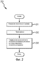
Фиг.2 изображает алгоритм генерирования временной метки, в соответствии с вариантом осуществления изобретения.Figure 2 depicts a time stamp generation algorithm in accordance with an embodiment of the invention.
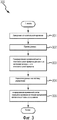
Фиг.3 изображает алгоритм генерирования временной метки, в соответствии с другим вариантом осуществления изобретения.Figure 3 depicts a time stamp generation algorithm in accordance with another embodiment of the invention.
Подробное описание изобретенияDETAILED DESCRIPTION OF THE INVENTION
Фиг.1-3 и следующее описание изображают конкретные примеры для обучения специалистов в данной области техники способу создания и использования лучшего варианта осуществления изобретения. Для обучения принципам изобретения некоторое количество обычных аспектов было упрощено или опущено. Специалистам в данной области техники должны быть очевидны вариации этих примеров, которые находятся в рамках объема изобретения. Специалистам в данной области техники должно быть понятно, что нижеописанные отличительные признаки могут быть объединены различными способами для формирования множества вариаций изобретения. В результате изобретение не ограничивается конкретными нижеописанными примерами, оно ограничивается только формулой изобретения и ее эквивалентами.1-3 and the following description depict specific examples for training specialists in the art to create and use the best embodiment of the invention. To teach the principles of the invention, a number of common aspects have been simplified or omitted. Variations to these examples, which are within the scope of the invention, should be apparent to those skilled in the art. Those skilled in the art will appreciate that the features described below can be combined in various ways to form many variations of the invention. As a result, the invention is not limited to the specific examples described below, it is limited only by the claims and their equivalents.
Фиг.1 изображает систему 100 обработки данных, в соответствии с вариантом осуществления изобретения. Изображенная на Фиг.1 система 100 обработки данных, в соответствии с вариантом осуществления, включает в себя измерительное устройство 101, передатчик 102 и систему 106 управления. Следует подразумевать, что наряду с тем, что представленное ниже обсуждение ориентировано на расходомер 101, передатчик 102 может принимать информацию от широкого спектра других устройств, а расходомер изображен исключительно в качестве одного примера. Следовательно, настоящее изобретение не должно ограничиваться расходомерами и измерениями расхода.1 shows a data processing system 100 in accordance with an embodiment of the invention. The data processing system 100 shown in FIG. 1, in accordance with an embodiment, includes a measurement device 101, a transmitter 102, and a control system 106. It should be understood that while the discussion below is focused on flowmeter 101, transmitter 102 can receive information from a wide range of other devices, and the flowmeter is shown solely as one example. Therefore, the present invention should not be limited to flow meters and flow measurements.
В соответствии с вариантом осуществления изобретения, передатчик 102 взаимодействует как с расходомером 101, так и с системой 106 управления. Связь может осуществляться по проводным выводам или в альтернативном варианте устройства могут взаимодействовать посредством использования технологии беспроводной связи, известной в уровне техники. В соответствии с вариантом осуществления изобретения, передатчик 102 включает в себя первый интерфейс 112 связи и второй интерфейс 105 связи. В соответствии с вариантом осуществления изобретения, интерфейс 112 связи может принимать данные, такие как информация об измерении расхода, от расходомера 101. В некоторых вариантах осуществления первый интерфейс 112 связи также может выводить информацию на расходомер 101. В соответствии с вариантом осуществления изобретения, передатчик 102 также включает в себя второй интерфейс 105 связи. Второй интерфейс 105 связи может передавать данные на систему 106 управления или подобное устройство для дальнейшей обработки и/или сохранения.In accordance with an embodiment of the invention, the transmitter 102 interacts with both the flowmeter 101 and the control system 106. Communication can be via wired terminals or, alternatively, devices can communicate using wireless technology known in the art. According to an embodiment of the invention, the transmitter 102 includes a first communication interface 112 and a second communication interface 105. According to an embodiment of the invention, the communication interface 112 may receive data, such as flow measurement information, from the flow meter 101. In some embodiments, the first communication interface 112 may also output information to the flow meter 101. According to an embodiment of the invention, the transmitter 102 also includes a second communication interface 105. The second communication interface 105 may transmit data to a control system 106 or the like for further processing and / or storage.
В соответствии с вариантом осуществления изобретения, наряду с другими параметрами расхода расходомер 101 может измерять коэффициент расхода, объемный расход, плотность жидкости и т.п. Расходомер 101 также может включать в себя устройство для измерения температуры, такое как RTD. Расходомер 101 может передавать параметры расхода на передатчик 102. Расходомер 101 может передавать параметры расхода на передатчик 102 практически сразу после измерения. Следовательно, передатчик 102 может принимать параметры расхода по мере измерения параметров расхода, выполняемого посредством расходомера 101. В зависимости от используемых для передачи информации компонентов может возникнуть задержка передачи. Задержка может быть вызвана либо посредством расходомера 101 либо посредством передатчика 102. Задержка также может возникнуть на время, требуемое для передачи информации с расходомера 101 на передатчик 102. Возможно придется учитывать задержку передачи при последующей обработке. В других вариантах осуществления задержка передачи может являться несущественной и, следовательно, время, в течение которого передатчик 102 принимает параметры расхода, может быть рассмотрено как содержащее время, в течение которого посредством расходомера 101 проводятся измерения.According to an embodiment of the invention, along with other flow parameters, the flow meter 101 may measure a flow coefficient, volumetric flow rate, liquid density, and the like. The flow meter 101 may also include a temperature measuring device, such as an RTD. The flow meter 101 can transmit the flow parameters to the transmitter 102. The flow meter 101 can transmit the flow parameters to the transmitter 102 almost immediately after the measurement. Therefore, the transmitter 102 may receive flow parameters as the flow parameters are measured by the flow meter 101. Depending on the components used to transmit the information, a transmission delay may occur. The delay can be caused either by means of the flow meter 101 or by the transmitter 102. The delay can also occur for the time required to transmit information from the flow meter 101 to the transmitter 102. It may be necessary to take into account the transmission delay during subsequent processing. In other embodiments, the transmission delay may not be significant and, therefore, the time during which the transmitter 102 receives the flow parameters can be considered as containing the time during which measurements are taken by the flow meter 101.
В соответствии с вариантом осуществления изобретения, получаемые от расходомера 101 данные могут быть сохранены в памяти 103 или подобном перед передачей на систему 106 управления для дальнейшей обработки. Память 103 может включать в себя таймер 104. Таймер 104 может измерять «относительное» время. К примеру, относительное время может содержать затраченное время. В соответствии с вариантом осуществления изобретения, затраченное время может указывать количество времени, в течение которого работал передатчик 102. В соответствии с другим вариантом осуществления изобретения, затраченное время может указывать количество времени, в течение которого передатчик 102 принимал данные. К примеру, таймер 104 относительного времени может содержать кварцевый кристалл. Однако таймер 104 не должен в обязательном порядке содержать кварцевый кристалл. Конкретный таймер, используемый в качестве таймера 104, не является важным элементом для осуществления настоящего изобретения и, следовательно, не должен ограничивать объем настоящего изобретения. В соответствии с вариантом осуществления изобретения, таймер 104 может быть сброшен и начат отсчет с момента сброса таймера в исходное состояние, при подаче питания на передатчик 102. Время сброса таймера в исходное состояние может являться нулем или же может являться некоторым другим предварительно определенным временем. Система 110 обработки передатчика 102 может пометить входящие данные относительным временем, измеренным посредством таймера 104. В соответствии с вариантом осуществления изобретения, относительное время основывается на затраченном времени, в течение которого работал передатчик 102, которое подсчитывается посредством таймера 104. В некоторых вариантах осуществления таймер 104 может предоставлять временную метку по мере сохранения данных в буферной памяти 103 вместо первого приема измерений.According to an embodiment of the invention, data received from the flow meter 101 may be stored in a memory 103 or the like before being transmitted to the control system 106 for further processing. The memory 103 may include a timer 104. The timer 104 may measure the "relative" time. For example, relative time may include elapsed time. According to an embodiment of the invention, the elapsed time may indicate the amount of time that the transmitter 102 has been operating. In accordance with another embodiment of the invention, the elapsed time may indicate the amount of time that the transmitter 102 has received data. For example, the relative time timer 104 may comprise a quartz crystal. However, the timer 104 should not necessarily contain a quartz crystal. The specific timer used as the timer 104 is not an important element for the implementation of the present invention and, therefore, should not limit the scope of the present invention. According to an embodiment of the invention, the timer 104 may be reset and counted down from the moment the timer was reset to the initial state when power was applied to the transmitter 102. The timer reset time may be zero or may be some other predetermined time. The processing system 110 of the transmitter 102 may mark the incoming data with a relative time measured by a timer 104. According to an embodiment of the invention, the relative time is based on the elapsed time during which the transmitter 102 is counted by the timer 104. In some embodiments, the timer 104 may provide a timestamp as data is stored in the buffer memory 103 instead of first receiving measurements.
В соответствии с вариантом осуществления изобретения, передатчик 102 может выводить данные, включающие в себя временную метку относительного времени, через информационный выход 105. Второй интерфейс 105 связи может содержать интерфейс любого типа, подходящий для передачи данных между передатчиком 102 и системой 106 управления. В некоторых вариантах осуществления второй интерфейс 105 связи также может принимать информацию от системы 106 управления. Второй интерфейс 105 связи может содержать проводные выводы или беспроводной интерфейс связи. Конкретный используемый интерфейс 105 может зависеть от конкретной ситуации. Например, если передатчик 102 располагается на большом расстоянии от системы 106 управления, то проводные выводы могут оказаться слишком дорогими, что является нецелесообразным. Следовательно, целесообразнее использовать беспроводной интерфейс.According to an embodiment of the invention, the transmitter 102 may output data including a relative time stamp via the information output 105. The second communication interface 105 may include any type of interface suitable for transmitting data between the transmitter 102 and the control system 106. In some embodiments, the second communication interface 105 may also receive information from the control system 106. The second communication interface 105 may comprise wired terminals or a wireless communication interface. The specific interface 105 used may depend on the particular situation. For example, if the transmitter 102 is located at a large distance from the control system 106, then the wired terminals may be too expensive, which is impractical. Therefore, it is more advisable to use a wireless interface.
Данные могут быть обработаны посредством использования временной метки относительного времени или в альтернативном варианте система управления, такая как система 106 управления, может обрабатывать данные, а также преобразовывать временную метку относительного времени в временную метку реального времени.Data may be processed by using a relative timestamp, or alternatively, a control system, such as a control system 106, may process the data and also convert the relative timestamp into a real-time timestamp.
В некоторых вариантах осуществления интерфейс 105 связи может выполнять передачу информации наряду с подачей питания на передатчик 102. Например, интерфейс 105 связи может содержать двухпроводную шину. Двухпроводные шины могут предоставить передатчику 102 возможность работы в искробезопасных средах, поскольку общий ток, подаваемый на передатчик 102, как правило, ограниченно изменяется в диапазоне 4-20 мА. В вариантах осуществления, в которых система 106 управления подает питание на передатчик 102, система 106 управления может беспрепятственно определить момент включения таймера 104 и, следовательно, может определить момент начала отсчета таймера 104. В других вариантах осуществления, в которых система 106 управления не подает питание на передатчик 102, передатчик 102 сразу после включения может передать сигнал на систему 106 управления. Сигнал, передаваемый на систему 106 управления, может информировать систему 106 управления о времени сброса таймера в исходное состояние или о времени запуска таймера. Система 111 обработки системы 106 управления может использовать время сброса таймера в исходное состояние для преобразования временной метки относительного времени в временную метку реального времени нижеописанным способом.In some embodiments, the communication interface 105 may transmit information along with supplying power to the transmitter 102. For example, the communication interface 105 may include a two-wire bus. Two-wire buses can provide transmitter 102 with the ability to operate in intrinsically safe environments since the total current supplied to transmitter 102 tends to be limited to a limited range of 4-20 mA. In embodiments in which the control system 106 supplies power to the transmitter 102, the control system 106 can freely determine when the timer 104 is turned on and, therefore, can determine the timing of the timer 104. In other embodiments, in which the control system 106 does not power to the transmitter 102, the transmitter 102 immediately after switching on can transmit a signal to the control system 106. The signal transmitted to the control system 106 may inform the control system 106 of the reset time of the timer or the start time of the timer. The processing system 111 of the control system 106 may use the timer reset time to convert the relative time stamp to a real time stamp in the manner described below.
В соответствии с вариантом осуществления, изображенным на Фиг.1, система 106 управления включает в себя интерфейс 109 связи, систему 111 обработки, память 107 и часы 108 реального времени. Система 106 управления может содержать универсальный компьютер, микропроцессорную систему, логическую схему, цифровой сигнальный процессор или любое другое универсальное или специализированное устройство обработки. Система 106 управления может быть распределена среди множества устройств обработки. Система 106 управления может включать в себя встроенную или отдельную электронную среду хранения любого типа, такую как внутренняя память 107. Следует понимать, что система 106 управления может включать в себя множество других компонентов, которые не изображены на чертежах, а также опущены в обсуждении для упрощения описания.According to the embodiment of FIG. 1, the control system 106 includes a communication interface 109, a processing system 111, a memory 107, and a real-time clock 108. The control system 106 may comprise a universal computer, microprocessor system, logic circuit, digital signal processor, or any other universal or specialized processing device. The control system 106 may be distributed among a plurality of processing devices. The control system 106 may include an embedded or separate electronic storage medium of any type, such as internal memory 107. It should be understood that the control system 106 may include many other components that are not shown in the drawings, and are also omitted from the discussion for simplicity descriptions.
Часы 108 реального времени, включенные в систему 106 управления, могут содержать часы реального времени, поскольку они обычно включаются в системы обработки. Часы 108 реального времени могут быть использованы в процессе выполнения алгоритма 200 генерирования временной метки нижеописанным способом.The real-time clock 108 included in the control system 106 may comprise a real-time clock, since it is typically included in processing systems. The real-time clock 108 can be used in the process of executing the
Фиг.2 изображает алгоритм 200 генерирования временной метки, в соответствии с вариантом осуществления изобретения. Алгоритм 200 генерирования временной метки может быть использован для предоставления временной метки относительного времени для данных, принимаемых посредством передатчика 102. Алгоритм 200 генерирования временной метки может начинаться на этапе 201, на котором измеряется относительное время. К примеру, относительное время может быть измерено посредством использования таймера 104. В соответствии с вариантом осуществления изобретения, таймер 104 может начинать отсчет при подаче питания на передатчик 102. В соответствии с вариантом осуществления изобретения, таймер 104 может продолжать измерение относительного времени до тех пор, пока не будет прервано питание, подаваемое на передатчик 102. Следовательно, таймер 104 может подсчитывать время, затраченное на работу передатчика 102.2 depicts a time
На этапе 202 передатчик 102 может принимать данные. К примеру, передатчик может принимать данные посредством первого интерфейса 112 связи. В вариантах осуществления, в которых передатчик 102 взаимодействует с расходомером, таким как расходомер 101, данные могут содержать информацию об измерении расхода. Однако следует подразумевать, что данные могут содержать любой тип данных, а также что настоящее изобретение не должно ограничиваться данными измерения расхода.At
На этапе 203 передатчик 102 и, в частности, система 110 обработки могут генерировать временную метку относительного времени для данных. Временная метка относительного времени может быть основана на относительном времени, измеряемом посредством таймера 104 на этапе 201. В соответствии с вариантом осуществления изобретения, данные помечаются временной меткой по мере сохранения в памяти 103. В соответствии с вариантом осуществления изобретения, время можно рассматривать в качестве «относительного» времени, поскольку временная метка не измеряется в качестве абсолютного или «реального» времени. Следует понимать, что под «реальным временем» подразумевается время, которое обычно используется в области или другом связанном оборудовании, а также которое может изменяться в зависимости от конкретного часового пояса, в котором располагается система 100 обработки данных. Напротив, «относительное время» генерируется (отсчитывается) с момента сброса таймера в исходное состояние, такого как ноль, и не является временем, которое обычно используется в области посредством пользователя/операторов или другого технического оборудования.At step 203, the transmitter 102 and, in particular, the processing system 110 may generate a relative timestamp for the data. The relative timestamp may be based on the relative time measured by the timer 104 in
Находящиеся в передатчике 102 данные, включающие в себя временную метку относительного времени, могут быть использованы без преобразования в реальное время. Например, в некоторых ситуациях реальное время, за которое принимается конкретная часть данных, может являться незначительным по сравнению с интервалом между последовательными частями данных. Следовательно, в некоторых вариантах осуществления временная метка относительного времени предоставляет достаточную информацию без последующей обработки. Однако если временная метка реального времени является необходимой или желательной, то вместо алгоритма 200 генерирования временной метки может быть использован алгоритм 300 генерирования временной метки.The data located in the transmitter 102, including the relative timestamp, can be used without conversion to real time. For example, in some situations, the real time for which a particular piece of data is taken may be small compared to the interval between consecutive pieces of data. Therefore, in some embodiments, the relative timestamp provides sufficient information without further processing. However, if the real-time timestamp is necessary or desirable, then the
Фиг.3 изображает алгоритм 300 генерирования временной метки, в соответствии с вариантом осуществления изобретения. Алгоритм 300 генерирования временной метки может быть использован для предоставления временной метки реального времени для данных, принимаемых посредством системы 106 управления от передатчика 102. Алгоритм 300 генерирования временной метки может начинаться на этапе 301, на котором измеряется относительное время. К примеру, относительное время может быть измерено посредством использования таймера 104. В соответствии с вариантом осуществления изобретения, таймер 104 может начинать отсчет при подаче питания на передатчик 102. В соответствии с вариантом осуществления изобретения, таймер 104 может продолжать измерение относительного времени до тех пор, пока не будет прервано питание, подаваемое на передатчик 102. Следовательно, таймер 104 может подсчитывать время, затраченное на работу передатчика 102.FIG. 3 depicts a
На этапе 302 передатчик 102 может принимать данные. К примеру, передатчик может принимать данные посредством первого интерфейса 112 связи. В вариантах осуществления, в которых передатчик 102 взаимодействует с расходомером, таким как расходомер 101, данные могут содержать информацию об измерении расхода. Однако следует подразумевать, что данные могут содержать любой тип данных, а также что настоящее изобретение не должно ограничиваться данными измерения расхода.At
На этапе 303 передатчик 102 и, в частности, система 110 обработки могут генерировать временную метку относительного времени для данных. Временная метка относительного времени может быть основана на относительном времени, измеряемом посредством таймера 104 на этапе 201. В соответствии с вариантом осуществления изобретения, данные помечаются временной меткой по мере сохранения в памяти 103.At
На этапе 304 сохраненные в передатчике 102 данные, которые были помечены временной меткой относительного времени, могут быть переданы на систему 106 управления. В соответствии с вариантом осуществления изобретения, временная метка относительного времени передается наряду с каждой частью данных.At
В соответствии с другим вариантом осуществления, передатчик 102 может помечать данные временной меткой через равные промежутки времени. Другими словами, не все данные будут включать в себя временную метку. Это может являться практичным, к примеру, если передатчик 102 принимает данные через регулярные интервалы. В соответствии с вариантом осуществления изобретения, передатчик 102 также может передать текущее затраченное время, которое предоставляется посредством таймера 104. К примеру, текущее затраченное время может оказаться полезным в случае, если данные не были переданы оперативно. Помимо всего прочего, текущее затраченное время может оказаться полезным в случае, к примеру, если система 106 управления не записала время запуска таймера 104.According to another embodiment, the transmitter 102 may timestamp the data at regular intervals. In other words, not all data will include a timestamp. This may be practical, for example, if the transmitter 102 receives data at regular intervals. According to an embodiment of the invention, the transmitter 102 can also transmit the current elapsed time, which is provided by the timer 104. For example, the current elapsed time may be useful in case the data has not been transferred promptly. Among other things, the current elapsed time may be useful in the case, for example, if the control system 106 has not recorded the start time of the timer 104.
На этапе 305 система 111 обработки системы 106 управления может сгенерировать временную метку реального времени для входящих данных. В соответствии с вариантом осуществления изобретения, временная метка реального времени может быть основана на текущем затраченном времени и временной метке относительного времени, предоставляемой посредством передатчика 102. В соответствии с другим вариантом осуществления изобретения, временная метка реального времени может быть основана на временной метке относительного времени и реальном времени запуска таймера 104. В соответствии с вариантом осуществления изобретения, текущее затраченное время может быть предоставлено посредством таймера 104 при передаче данных с передатчика 102 на систему 106 управления. В соответствии с вариантом осуществления изобретения, текущее реальное время может быть предоставлено посредством часов 108 реального времени, включенных в состав системы 106 управления. Временная метка реального времени может быть вычислена посредством вычитания текущего затраченного времени, предоставляемого посредством таймера 104, из текущего реального времени, предоставляемого посредством часов 108 реального времени. Такое вычисление может определить реальное время запуска таймера 104. Другими словами, может быть определено реальное время, когда таймер 104 начал отсчет. С момента запуска таймера и временной метки относительного времени, предоставляемой посредством таймера 104, временная метка реального времени может быть предоставлена для каждого измерения посредством сложения реального времени запуска таймера с временной меткой относительного времени. Другими словами, время запуска таймера может быть добавлено к затраченному времени для каждого измерения, что в свою очередь обеспечит временную метку реального времени. Это создаст иллюзию того, что передатчик 102 включает в себя часы реального времени, такие как часы 108 реального времени, обеспеченные в системе 106 управления, наряду с тем, что передатчик 102 включает в себя только таймер 104 относительного времени.At 305, the processing system 111 of the control system 106 may generate a real-time time stamp for incoming data. According to an embodiment of the invention, the real-time timestamp can be based on the elapsed time and the relative timestamp provided by the transmitter 102. According to another embodiment of the invention, the real-time timestamp can be based on the relative timestamp and real-time start timer 104. In accordance with an embodiment of the invention, the current elapsed time can be provided by m timer 104 in the transmission data from the transmitter 102 to the control system 106. According to an embodiment of the invention, the current real time can be provided by the real-time clock 108 included in the control system 106. The real-time timestamp can be calculated by subtracting the current elapsed time provided by the timer 104 from the current real-time provided by the real-time clock 108. Such a calculation can determine the actual start time of the timer 104. In other words, the real time that the timer 104 has started counting can be determined. From the start of the timer and the relative timestamp provided by the timer 104, a real-time timestamp can be provided for each measurement by adding the real-time start of the timer to the relative timestamp. In other words, the timer start time can be added to the elapsed time for each measurement, which in turn will provide a real-time timestamp. This will create the illusion that the transmitter 102 includes a real-time clock, such as a real-time clock 108 provided in the control system 106, while the transmitter 102 includes only a relative time timer 104.
В некоторых вариантах осуществления текущее затраченное время может оказаться недоступным. Например, передатчик 102 не сможет передать текущее затраченное время. Следовательно, как было упомянуто выше, система 106 управления может отследить реальное время запуска таймера 104. Следовательно, система 106 управления может отследить реальное время запуска таймера без необходимости в вычислении времени запуска таймера в дальнейшем. В соответствии с этим вариантом осуществления, временная метка реального времени может быть вычислена на основе временной метки относительного времени и реального времени запуска таймера. Когда система 106 управления принимает данные от передатчика 102 наряду с временной меткой относительного времени, система 106 управления может беспрепятственно сравнить временную метку относительного времени с реальным временем запуска таймера, которое записывается посредством системы 106 управления. К примеру, сравнение может содержать сложение реального времени запуска таймера с временной меткой относительного времени. Однако конкретное сравнение может зависеть от времени сброса временной метки относительного времени. Например, если время сброса таймера в исходное состояние содержит 24:00:00, а не 00:00:00, то сравнение может содержать вычитание временной метки относительного времени из реального времени запуска таймера. Следовательно, текущее затраченное время не должно передаваться посредством передатчика 102 для вычисления временной метки реального времени.In some embodiments, the current elapsed time may not be available. For example, the transmitter 102 will not be able to transmit the current elapsed time. Therefore, as mentioned above, the control system 106 can track the real time of the start of the timer 104. Therefore, the control system 106 can track the real time of the start of the timer without the need to calculate the timer start time in the future. According to this embodiment, the real-time timestamp can be calculated based on the relative timestamp and the real-time timer start. When the control system 106 receives data from the transmitter 102 along with the relative time stamp, the control system 106 can seamlessly compare the relative time stamp with the actual timer start time, which is recorded by the control system 106. For example, a comparison may include adding a real-time timer trigger to a relative timestamp. However, a specific comparison may depend on the reset time of the relative timestamp. For example, if the timer reset time contains 24:00:00 rather than 00:00:00, then the comparison may include subtracting the relative timestamp from the real time of the timer. Therefore, the current elapsed time should not be transmitted by the transmitter 102 to calculate the real-time time stamp.
В соответствии с вариантом осуществления изобретения, система 106 управления может скорректировать время передачи, требуемое для передачи данных с расходомера 101 на передатчик 102, а также время передачи, требуемое для передачи данных с передатчика 102 на систему 106 управления. К примеру, коррекция может содержать вычитание предварительно определенного количества времени из текущего затраченного времени, предоставляемого посредством таймера 104. В соответствии с другим вариантом осуществления изобретения, коррекция может содержать вычитание предварительно определенного количества времени из часов 108 реального времени.According to an embodiment of the invention, the control system 106 may adjust the transmission time required for data transmission from the flow meter 101 to the transmitter 102, as well as the transmission time required for data transmission from the transmitter 102 to the control system 106. For example, the correction may comprise subtracting a predetermined amount of time from the current elapsed time provided by the timer 104. According to another embodiment of the invention, the correction may include subtracting the predetermined amount of time from the real-time clock 108.
Вышеописанные способ и устройство обеспечивают эффективный и экономичный подход к предоставлению временной метки относительного времени для данных, принимаемых посредством передатчика. В некоторых вариантах осуществления изобретение может впоследствии сгенерировать временную метку реального времени для данных, передаваемых на систему управления без недостатков, связанных с системами предшествующего уровня техники. Несмотря на то, что изобретение было описано в качестве включающего в себя расходомер, следует понимать, что настоящее изобретение является в равной мере применимым к другим системам передачи данных и, следовательно, не должно ограничиваться конкретными представленными примерами.The above method and apparatus provide an efficient and economical approach to providing a relative timestamp for data received by a transmitter. In some embodiments, the invention may subsequently generate a real-time time stamp for data transmitted to the control system without the disadvantages associated with prior art systems. Although the invention has been described as including a flow meter, it should be understood that the present invention is equally applicable to other data transmission systems and, therefore, should not be limited to the specific examples presented.
Следует понимать, что наряду с тем, что конкретные представленные варианты осуществления описывали передатчик 102, соединенный с системой 106 управления, также могут быть рассмотрены и другие конфигурации, не выходящие за пределы объема формулы изобретения. Например, система 106 управления может принимать данные, включающие в себя временную метку относительного времени не только от передатчика, но и от различных других источников. Помимо всего прочего, передатчик 102 может выводить данные, помеченные временной меткой относительного времени, не только на систему 106 управления, но и на различные другие компоненты. Следовательно, следует понимать, что каждый из вышеописанных компонентов может быть использован отдельно или же в комбинации друг с другом.It should be understood that while the specific embodiments presented have described a transmitter 102 connected to the control system 106, other configurations may also be considered without departing from the scope of the claims. For example, the control system 106 may receive data including a relative timestamp not only from the transmitter, but also from various other sources. In addition, the transmitter 102 can output data marked with a relative timestamp, not only to the control system 106, but also to various other components. Therefore, it should be understood that each of the above components can be used separately or in combination with each other.
Подробное описание вышеупомянутых вариантов осуществления не является полным описанием всех вариантов осуществления, рассмотренных изобретателями в объеме изобретения. Безусловно, специалисты в данной области техники признают, что для создания дополнительных вариантов осуществления некоторые элементы вышеописанных вариантов осуществления могут быть объединены или удалены разными способами, и такие дополнительные варианты осуществления не должны выходить за пределы объема и идей изобретения. Специалистам в данной области техники также будет понятно, что для создания дополнительных вариантов осуществления, которые не должны выходить за пределы объема и идей изобретения, вышеописанные варианты осуществления могут быть объединены полностью или частично.A detailed description of the above embodiments is not a complete description of all embodiments contemplated by the inventors within the scope of the invention. Of course, those skilled in the art will recognize that to create additional embodiments, some elements of the above described embodiments may be combined or removed in various ways, and such additional embodiments should not go beyond the scope and ideas of the invention. Those skilled in the art will also understand that to create additional embodiments that should not fall outside the scope and ideas of the invention, the above-described embodiments may be combined in whole or in part.
Следовательно, несмотря на то, что конкретные варианты осуществления и примеры изобретения были описаны в настоящем документе в иллюстративных целях, возможны различные эквивалентные модификации, не выходящие за пределы объема изобретения, которые распознаны специалистами уровня техники. Представленные в настоящем документе идеи могут быть применены не только к вышеописанным и изображенным на сопроводительных чертежах вариантам осуществления, но и к другим передатчикам. Соответственно, объем изобретения должен быть определен посредством следующей формулы изобретения.Therefore, although specific embodiments and examples of the invention have been described herein for illustrative purposes, various equivalent modifications are possible without departing from the scope of the invention as recognized by those skilled in the art. The ideas presented herein can be applied not only to the embodiments described above and depicted in the accompanying drawings, but also to other transmitters. Accordingly, the scope of the invention should be determined by the following claims.
Claims (20)
передают данные на систему управления, причем система управления измеряет реальное время и генерируют временную метку реального времени на основе временной метки относительного времени.15. The method according to claim 11, further comprising stages, in which
transmitting data to the control system, the control system measuring the real time and generating a real time time stamp based on the relative time stamp.
Applications Claiming Priority (1)
| Application Number | Priority Date | Filing Date | Title |
|---|---|---|---|
| PCT/US2008/083432 WO2010056246A1 (en) | 2008-11-13 | 2008-11-13 | Transmitter with a relative-time timer |
Publications (2)
| Publication Number | Publication Date |
|---|---|
| RU2011123747A RU2011123747A (en) | 2012-12-20 |
| RU2483471C2 true RU2483471C2 (en) | 2013-05-27 |
Family
ID=41009942
Family Applications (1)
| Application Number | Title | Priority Date | Filing Date |
|---|---|---|---|
| RU2011123747/07A RU2483471C2 (en) | 2008-11-13 | 2008-11-13 | Transmitter with relative time timer |
Country Status (13)
| Country | Link |
|---|---|
| US (1) | US9820019B2 (en) |
| EP (1) | EP2356821B1 (en) |
| JP (1) | JP2012508926A (en) |
| KR (1) | KR101244334B1 (en) |
| CN (1) | CN102217326B (en) |
| AR (1) | AR074657A1 (en) |
| AU (1) | AU2008364001B2 (en) |
| BR (1) | BRPI0823252B1 (en) |
| CA (1) | CA2743511C (en) |
| HK (1) | HK1162800A1 (en) |
| MX (1) | MX2011004354A (en) |
| RU (1) | RU2483471C2 (en) |
| WO (1) | WO2010056246A1 (en) |
Families Citing this family (8)
| Publication number | Priority date | Publication date | Assignee | Title |
|---|---|---|---|---|
| JP5138760B2 (en) * | 2010-11-10 | 2013-02-06 | 富士通テン株式会社 | Information recording device |
| JP5565431B2 (en) * | 2012-04-18 | 2014-08-06 | 横河電機株式会社 | Control device and control system |
| DE102012207138A1 (en) | 2012-04-27 | 2013-10-31 | Robert Bosch Gmbh | Sensor time synchronization |
| DE102012207026A1 (en) * | 2012-04-27 | 2013-10-31 | Robert Bosch Gmbh | Sensor time (sensor time) |
| DE102013105517A1 (en) * | 2013-05-29 | 2014-12-18 | Weidmüller Interface GmbH & Co. KG | Method for detecting a transmitter local time in a receiver |
| JP2015035158A (en) * | 2013-08-09 | 2015-02-19 | ルネサスエレクトロニクス株式会社 | Data processing system |
| JP6846111B2 (en) * | 2016-02-26 | 2021-03-24 | オムロン株式会社 | Master device, slave device, information processing device, event log collection system, master device control method, slave device control method, and control program |
| US10296602B1 (en) * | 2017-04-18 | 2019-05-21 | X Development Llc | Determining real-time timestamps for robotic sensor data |
Citations (9)
| Publication number | Priority date | Publication date | Assignee | Title |
|---|---|---|---|---|
| US5027297A (en) * | 1989-09-29 | 1991-06-25 | Abb Power T & D Company Inc. | System for time stamping events using a remote master clock |
| KR910007399B1 (en) * | 1988-04-16 | 1991-09-25 | 손병선 | Device which transfers data inspected remotely |
| US6336900B1 (en) * | 1999-04-12 | 2002-01-08 | Agilent Technologies, Inc. | Home hub for reporting patient health parameters |
| EP1239620A2 (en) * | 2001-03-06 | 2002-09-11 | Chrysalis- ITS Inc. | Relative time synchronization between three or more systems |
| US6633825B2 (en) * | 2001-06-29 | 2003-10-14 | Siemens Power Transmission & Distribution, Inc. | Automatic calibration of time keeping for utility meters |
| US6876952B1 (en) * | 2003-04-30 | 2005-04-05 | Cisco Technology, Inc. | Methods and apparatus for maintaining queues |
| US6946972B2 (en) * | 2001-01-25 | 2005-09-20 | Smartsynch, Inc. | Systems and methods for wirelessly transmitting data from a utility meter |
| SU1840576A1 (en) * | 1987-01-09 | 2007-09-10 | Российский институт радионавигации и времени | System for synchronizing timers via radio channel |
| US7433321B2 (en) * | 2001-07-09 | 2008-10-07 | Qualcomm Incorporated | Method and apparatus for time-aligning transmissions from multiple base stations in a CDMA communication system |
Family Cites Families (13)
| Publication number | Priority date | Publication date | Assignee | Title |
|---|---|---|---|---|
| US5825648A (en) * | 1996-03-26 | 1998-10-20 | Casio Phonemate, Inc. | Backup system for a time of day clock in an electronic device |
| US6014089A (en) * | 1996-10-28 | 2000-01-11 | Tracy Corporation Ii | Method for transmitting data using a digital control channel of a wireless network |
| US6078873A (en) * | 1997-10-02 | 2000-06-20 | Cummins Engine Company, Inc. | Method and apparatus for real-time data stamping via datalink and volatile ECM timer/clock |
| JP2000135458A (en) | 1998-10-30 | 2000-05-16 | Tokico Ltd | Robot device for coating |
| JP2004272403A (en) | 2003-03-06 | 2004-09-30 | Mitsubishi Electric Corp | Process input/output device and monitor control system using the same |
| JP2004303208A (en) * | 2003-03-20 | 2004-10-28 | Seiko Epson Corp | Oscillator and electronic equipment using the same |
| JP4267396B2 (en) | 2003-07-23 | 2009-05-27 | 株式会社日立国際電気 | Abnormality memory circuit |
| JP2007038326A (en) | 2005-08-01 | 2007-02-15 | Toyota Motor Corp | Robot control system |
| GB2443868A (en) * | 2006-03-21 | 2008-05-21 | Zarlink Semiconductor Ltd | Synchronising slave clocks in non-symmetric packet networks |
| CN101056249A (en) | 2006-04-12 | 2007-10-17 | 华为技术有限公司 | A method and system for transmitting the multicast broadcast information |
| CN101197944A (en) | 2006-12-06 | 2008-06-11 | 中兴通讯股份有限公司 | Method for implementing video and words synchronization by medium service apparatus |
| US20080228331A1 (en) * | 2007-03-14 | 2008-09-18 | Boeing Company A Corporation Of Delaware | System and method for measuring parameters at aircraft loci |
| CN100495993C (en) | 2007-04-02 | 2009-06-03 | 华为技术有限公司 | Method, device, system and communication method for detecting the host number |
-
2008
- 2008-11-13 US US13/124,695 patent/US9820019B2/en active Active
- 2008-11-13 CN CN200880131964.2A patent/CN102217326B/en active Active
- 2008-11-13 AU AU2008364001A patent/AU2008364001B2/en active Active
- 2008-11-13 EP EP08876452.7A patent/EP2356821B1/en active Active
- 2008-11-13 CA CA2743511A patent/CA2743511C/en active Active
- 2008-11-13 RU RU2011123747/07A patent/RU2483471C2/en active
- 2008-11-13 JP JP2011536294A patent/JP2012508926A/en active Pending
- 2008-11-13 MX MX2011004354A patent/MX2011004354A/en active IP Right Grant
- 2008-11-13 WO PCT/US2008/083432 patent/WO2010056246A1/en active Application Filing
- 2008-11-13 BR BRPI0823252-0A patent/BRPI0823252B1/en active IP Right Grant
- 2008-11-13 KR KR1020117013502A patent/KR101244334B1/en active IP Right Grant
-
2009
- 2009-11-10 AR ARP090104337A patent/AR074657A1/en active IP Right Grant
-
2012
- 2012-04-02 HK HK12103255.0A patent/HK1162800A1/en unknown
Patent Citations (9)
| Publication number | Priority date | Publication date | Assignee | Title |
|---|---|---|---|---|
| SU1840576A1 (en) * | 1987-01-09 | 2007-09-10 | Российский институт радионавигации и времени | System for synchronizing timers via radio channel |
| KR910007399B1 (en) * | 1988-04-16 | 1991-09-25 | 손병선 | Device which transfers data inspected remotely |
| US5027297A (en) * | 1989-09-29 | 1991-06-25 | Abb Power T & D Company Inc. | System for time stamping events using a remote master clock |
| US6336900B1 (en) * | 1999-04-12 | 2002-01-08 | Agilent Technologies, Inc. | Home hub for reporting patient health parameters |
| US6946972B2 (en) * | 2001-01-25 | 2005-09-20 | Smartsynch, Inc. | Systems and methods for wirelessly transmitting data from a utility meter |
| EP1239620A2 (en) * | 2001-03-06 | 2002-09-11 | Chrysalis- ITS Inc. | Relative time synchronization between three or more systems |
| US6633825B2 (en) * | 2001-06-29 | 2003-10-14 | Siemens Power Transmission & Distribution, Inc. | Automatic calibration of time keeping for utility meters |
| US7433321B2 (en) * | 2001-07-09 | 2008-10-07 | Qualcomm Incorporated | Method and apparatus for time-aligning transmissions from multiple base stations in a CDMA communication system |
| US6876952B1 (en) * | 2003-04-30 | 2005-04-05 | Cisco Technology, Inc. | Methods and apparatus for maintaining queues |
Also Published As
| Publication number | Publication date |
|---|---|
| US20110207417A1 (en) | 2011-08-25 |
| CA2743511C (en) | 2018-06-12 |
| CN102217326B (en) | 2016-07-06 |
| CA2743511A1 (en) | 2010-05-20 |
| US9820019B2 (en) | 2017-11-14 |
| CN102217326A (en) | 2011-10-12 |
| BRPI0823252B1 (en) | 2020-09-15 |
| AR074657A1 (en) | 2011-02-02 |
| AU2008364001B2 (en) | 2014-02-13 |
| AU2008364001A1 (en) | 2010-05-20 |
| EP2356821A1 (en) | 2011-08-17 |
| HK1162800A1 (en) | 2012-08-31 |
| RU2011123747A (en) | 2012-12-20 |
| KR101244334B1 (en) | 2013-03-18 |
| JP2012508926A (en) | 2012-04-12 |
| EP2356821B1 (en) | 2019-06-19 |
| WO2010056246A1 (en) | 2010-05-20 |
| KR20110095327A (en) | 2011-08-24 |
| MX2011004354A (en) | 2011-05-24 |
| BRPI0823252A2 (en) | 2015-06-23 |
Similar Documents
| Publication | Publication Date | Title |
|---|---|---|
| RU2483471C2 (en) | Transmitter with relative time timer | |
| JP5373260B2 (en) | Accident point location method and system for transmission and distribution systems | |
| CN201466800U (en) | Improved time synchronization tester | |
| CN104570824A (en) | Event input module | |
| CN102405446A (en) | Field device with measurement accuracy reporting | |
| KR102051732B1 (en) | Advanced remote meter reading system | |
| KR102167912B1 (en) | Metering Data Collection Unit with Battery Energy Calculator and Ultrasonic Meter and Remote Data Collectioin System Having the Same | |
| JP2012508926A5 (en) | ||
| KR100850638B1 (en) | Measuring meter system with wireless remote meter reading function | |
| CN111756466B (en) | Method and system for synchronizing clocks of platform sensing terminals based on platform power failure event grabbing | |
| JP6738896B2 (en) | Detecting error conditions by monitoring resource flow within the facility | |
| JP5766580B2 (en) | Remote monitoring device | |
| CN210375231U (en) | Field device and flow meter | |
| JP5855170B2 (en) | Transmitter with relative time timer | |
| JP7091156B2 (en) | Pulse generator | |
| JP2017116480A (en) | Watthour meter | |
| CN102889915A (en) | Flowmeter and calorimeter asynchronous metering and detecting method and flowmeter and calorimeter asynchronous metering and detecting system based on communication | |
| JP7134030B2 (en) | Communication system and slave device | |
| JP2012088202A (en) | Timepiece device | |
| JP2008304335A (en) | Measurement control system and measuring quantity receiver | |
| US20200371143A1 (en) | Timestamp inconsistency and shift detection for synchrophasor data based on correlation between relative phase angle and frequency | |
| JPS6022855B2 (en) | Weighing data transfer method | |
| JP2020107959A (en) | Communication system | |
| JP2021096680A (en) | Meter reading device and meter reading method | |
| JP2008108167A (en) | Automatic meter reading wireless system |