RU2478799C2 - Seal of steam flow path in steam turbine driven by pressure - Google Patents
Seal of steam flow path in steam turbine driven by pressure Download PDFInfo
- Publication number
- RU2478799C2 RU2478799C2 RU2009139894/06A RU2009139894A RU2478799C2 RU 2478799 C2 RU2478799 C2 RU 2478799C2 RU 2009139894/06 A RU2009139894/06 A RU 2009139894/06A RU 2009139894 A RU2009139894 A RU 2009139894A RU 2478799 C2 RU2478799 C2 RU 2478799C2
- Authority
- RU
- Russia
- Prior art keywords
- diaphragm
- gap
- outer ring
- piston
- steam turbine
- Prior art date
Links
Images


Classifications
-
- F—MECHANICAL ENGINEERING; LIGHTING; HEATING; WEAPONS; BLASTING
- F01—MACHINES OR ENGINES IN GENERAL; ENGINE PLANTS IN GENERAL; STEAM ENGINES
- F01D—NON-POSITIVE DISPLACEMENT MACHINES OR ENGINES, e.g. STEAM TURBINES
- F01D11/00—Preventing or minimising internal leakage of working-fluid, e.g. between stages
- F01D11/08—Preventing or minimising internal leakage of working-fluid, e.g. between stages for sealing space between rotor blade tips and stator
- F01D11/14—Adjusting or regulating tip-clearance, i.e. distance between rotor-blade tips and stator casing
- F01D11/20—Actively adjusting tip-clearance
- F01D11/22—Actively adjusting tip-clearance by mechanically actuating the stator or rotor components, e.g. moving shroud sections relative to the rotor
-
- F—MECHANICAL ENGINEERING; LIGHTING; HEATING; WEAPONS; BLASTING
- F01—MACHINES OR ENGINES IN GENERAL; ENGINE PLANTS IN GENERAL; STEAM ENGINES
- F01D—NON-POSITIVE DISPLACEMENT MACHINES OR ENGINES, e.g. STEAM TURBINES
- F01D11/00—Preventing or minimising internal leakage of working-fluid, e.g. between stages
- F01D11/02—Preventing or minimising internal leakage of working-fluid, e.g. between stages by non-contact sealings, e.g. of labyrinth type
- F01D11/025—Seal clearance control; Floating assembly; Adaptation means to differential thermal dilatations
-
- F—MECHANICAL ENGINEERING; LIGHTING; HEATING; WEAPONS; BLASTING
- F01—MACHINES OR ENGINES IN GENERAL; ENGINE PLANTS IN GENERAL; STEAM ENGINES
- F01D—NON-POSITIVE DISPLACEMENT MACHINES OR ENGINES, e.g. STEAM TURBINES
- F01D11/00—Preventing or minimising internal leakage of working-fluid, e.g. between stages
- F01D11/08—Preventing or minimising internal leakage of working-fluid, e.g. between stages for sealing space between rotor blade tips and stator
- F01D11/12—Preventing or minimising internal leakage of working-fluid, e.g. between stages for sealing space between rotor blade tips and stator using a rubstrip, e.g. erodible. deformable or resiliently-biased part
-
- F—MECHANICAL ENGINEERING; LIGHTING; HEATING; WEAPONS; BLASTING
- F01—MACHINES OR ENGINES IN GENERAL; ENGINE PLANTS IN GENERAL; STEAM ENGINES
- F01D—NON-POSITIVE DISPLACEMENT MACHINES OR ENGINES, e.g. STEAM TURBINES
- F01D11/00—Preventing or minimising internal leakage of working-fluid, e.g. between stages
- F01D11/08—Preventing or minimising internal leakage of working-fluid, e.g. between stages for sealing space between rotor blade tips and stator
- F01D11/14—Adjusting or regulating tip-clearance, i.e. distance between rotor-blade tips and stator casing
- F01D11/16—Adjusting or regulating tip-clearance, i.e. distance between rotor-blade tips and stator casing by self-adjusting means
-
- F—MECHANICAL ENGINEERING; LIGHTING; HEATING; WEAPONS; BLASTING
- F01—MACHINES OR ENGINES IN GENERAL; ENGINE PLANTS IN GENERAL; STEAM ENGINES
- F01D—NON-POSITIVE DISPLACEMENT MACHINES OR ENGINES, e.g. STEAM TURBINES
- F01D5/00—Blades; Blade-carrying members; Heating, heat-insulating, cooling or antivibration means on the blades or the members
- F01D5/12—Blades
- F01D5/22—Blade-to-blade connections, e.g. for damping vibrations
- F01D5/225—Blade-to-blade connections, e.g. for damping vibrations by shrouding
-
- F—MECHANICAL ENGINEERING; LIGHTING; HEATING; WEAPONS; BLASTING
- F05—INDEXING SCHEMES RELATING TO ENGINES OR PUMPS IN VARIOUS SUBCLASSES OF CLASSES F01-F04
- F05D—INDEXING SCHEME FOR ASPECTS RELATING TO NON-POSITIVE-DISPLACEMENT MACHINES OR ENGINES, GAS-TURBINES OR JET-PROPULSION PLANTS
- F05D2220/00—Application
- F05D2220/30—Application in turbines
- F05D2220/31—Application in turbines in steam turbines
Abstract
Description
Уровень техникиState of the art
Настоящее изобретение, в общем, относится к уплотнителям между вращающимся и неподвижным компонентами паровой турбины, а более конкретно к уплотнителю, приводимому в действие перепадом давлений, образованным между вращающимся компонентом и неподвижным компонентом паровой турбины.The present invention relates generally to seals between a rotating and stationary components of a steam turbine, and more particularly, to a seal driven by a differential pressure formed between a rotating component and a stationary component of a steam turbine.
В паровой турбине уплотнение между вращающимися и неподвижными компонентами является важной частью производительности паровой турбины. Следует понимать, что чем больше количество и величина путей утечки пара, тем больше потерь эффективности паровой турбины. Например, зубцы лабиринтного уплотнения, часто используемые для уплотнения между диафрагмами неподвижного компонента и ротором или между венцами лопаток ротора и неподвижным бандажом вращающегося компонента, требуют поддержания значительных зазоров для обеспечения радиального и кругового перемещения во время переходных режимов, например, запуска и остановки паровой турбины. Эти зазоры, конечно, вредят уплотнению. Также существуют проблемы с зазорами, связанные с множественными независимыми поверхностями уплотнений, наложением допусков радиальных зазоров и узлом множественных уплотнений, которые могут уменьшать эффективность паровой турбины. Кроме того, часто трудно создавать уплотнения, которые не только увеличивают эффективность паровой турбины, но также увеличивают возможность обслуживания и ремонта различных частей турбины, а также создания известных повторяющихся граничных условий для таких частей.In a steam turbine, the seal between rotating and stationary components is an important part of the performance of a steam turbine. It should be understood that the greater the number and magnitude of steam leakage paths, the greater the loss in efficiency of a steam turbine. For example, labyrinth seal teeth, often used to seal between the diaphragms of the fixed component and the rotor, or between the rims of the rotor blades and the fixed band of the rotating component, require significant clearances to ensure radial and circular movement during transient conditions, such as starting and stopping a steam turbine. These gaps, of course, damage the seal. There are also problems with clearances associated with multiple independent seal surfaces, overlapping tolerances of radial clearances, and multiple seal assemblies that can reduce the efficiency of a steam turbine. In addition, it is often difficult to create seals that not only increase the efficiency of the steam turbine, but also increase the ability to service and repair various parts of the turbine, as well as create known repetitive boundary conditions for such parts.
Раскрытие изобретенияDisclosure of invention
Согласно одному аспекту настоящего изобретения предложена паровая турбина. Паровая турбина содержит вращающийся компонент, включающий в себя множество разнесенных по окружности лопаток, которые разнесены в аксиальных положениях. Каждая из множества лопаток имеет венец с примыкающей бандажной полкой, которая включает в себя один или более уплотнительных зубцов. Паровая турбина также содержит неподвижный компонент, включающий в себя множество диафрагм, каждая из которых имеет наружное кольцо диафрагмы и внутреннее кольцо диафрагмы, отделенные посредством установочной перегородки. Множество диафрагм расположено аксиально между смежными рядами множества лопаток. Каждый ряд образует ступень турбины, которая образует участок пути прохода пара через турбину. Каждое наружное кольцо диафрагмы имеет канал, выполненный в нем, который соединяет конец высокого давления с концом низкого давления. Паровая турбина также содержит закрывающий зазор компонент, расположенный около вращающегося компонента и неподвижного компонента для уплотнения участка пути утечки пара. Закрывающий зазор компонент содержит множество закрывающих зазор устройств. Каждое из множества закрывающих зазор устройств расположено около каждого соответствующего наружного кольца диафрагмы и одного или более уплотнительных зубцов бандажной полки лопатки. Каждое из множества закрывающих зазор устройств приводится в действие перепадом давления, образуемым в канале соответствующего наружного кольца диафрагмы, которое обеспечивает уплотнение пути утечки пара посредством одного или более уплотнительных зубцов бандажной полки лопатки и наружного кольца диафрагмы.According to one aspect of the present invention, there is provided a steam turbine. The steam turbine comprises a rotating component including a plurality of circumferentially spaced vanes that are spaced apart in axial positions. Each of the multiple blades has a crown with an adjoining retaining shelf, which includes one or more sealing teeth. The steam turbine also comprises a fixed component including a plurality of diaphragms, each of which has an outer diaphragm ring and an inner diaphragm ring separated by a mounting baffle. Many diaphragms are axially located between adjacent rows of multiple blades. Each row forms a turbine stage, which forms a portion of the steam path through the turbine. Each outer ring of the diaphragm has a channel made in it, which connects the end of the high pressure end of the low pressure. The steam turbine also includes a gap-closing component located near the rotating component and the stationary component to seal the portion of the steam leak path. The gap-closing component comprises a plurality of gap-closing devices. Each of the plurality of gap-closing devices is located near each respective outer diaphragm ring and one or more sealing teeth of the blade retaining shelf. Each of the plurality of gap-closing devices is driven by a pressure differential generated in the channel of the corresponding outer diaphragm ring, which provides sealing of the steam leak path through one or more sealing teeth of the blade retaining shelf and the diaphragm outer ring.
Краткое описание чертежейBrief Description of the Drawings
Фиг.1 представляет собой частичный вид в сечении участка паровой турбины, иллюстрирующий различные уплотнения согласно уровню техники;Figure 1 is a partial sectional view of a portion of a steam turbine illustrating various seals according to the prior art;
фиг.2 представляет собой схематичный вид в сечении закрывающего зазор устройства согласно первому варианту осуществления настоящего изобретения;FIG. 2 is a schematic cross-sectional view of a gap-closing device according to a first embodiment of the present invention; FIG.
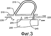
фиг.3 представляет собой схематичный вид в сечении, показывающий закрывающее зазор устройство, показанное на фиг.2, в рабочем состоянии при наличии перепада давления;FIG. 3 is a schematic cross-sectional view showing the gap-closing device shown in FIG. 2 in an operational state in the presence of a differential pressure;
фиг.4 представляет собой схематичный вид в сечении закрывающего зазор устройства согласно второму варианту осуществления настоящего изобретения;4 is a schematic sectional view of a gap-closing device according to a second embodiment of the present invention;
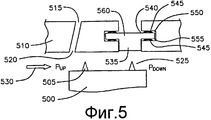
фиг.5 представляет собой схематичный вид в сечении закрывающего зазор устройства согласно третьему варианту осуществления настоящего изобретения;5 is a schematic sectional view of a gap-closing device according to a third embodiment of the present invention;
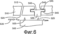
фиг.6 представляет собой схематичный вид в сечении, показывающий закрывающее зазор устройство, показанное на фиг.5, в рабочем состоянии при наличии перепада давления;6 is a schematic cross-sectional view showing the gap-closing device shown in FIG. 5 in an operational state in the presence of a pressure differential;
фиг.7 представляет собой схематичный вид в сечении закрывающего зазор устройства согласно четвертому варианту осуществления настоящего изобретения;7 is a schematic sectional view of a gap-closing device according to a fourth embodiment of the present invention;
фиг.8 представляет собой схематичный вид в сечении, показывающий закрывающее зазор устройство, показанное на фиг.7, в рабочем состоянии при наличии перепада давления;Fig. 8 is a schematic cross-sectional view showing the gap-closing device of Fig. 7 in an operational state in the presence of a pressure differential;
фиг.9 представляет собой схематичный вид в сечении закрывающего зазор устройства согласно пятому варианту осуществления настоящего изобретения;Fig. 9 is a schematic sectional view of a gap-closing device according to a fifth embodiment of the present invention;
фиг.10 представляет собой схематичный вид в сечении, показывающий закрывающее зазор устройство, показанное на фиг.9, в рабочем состоянии при наличии перепада давления;figure 10 is a schematic view in section, showing the closing gap device shown in figure 9, in working condition in the presence of a differential pressure;
фиг.11 представляет собой схематичный вид в сечении закрывающего зазор устройства согласно шестому варианту осуществления настоящего изобретения; и11 is a schematic sectional view of a gap-closing device according to a sixth embodiment of the present invention; and
фиг.12 представляет собой схематичный вид в сечении, показывающий закрывающее зазор устройство, показанное на фиг.11, в рабочем состоянии при наличии перепада давления.12 is a schematic sectional view showing the gap-closing device shown in FIG. 11 in an operational state in the presence of a pressure differential.
Подробное описание изобретенияDETAILED DESCRIPTION OF THE INVENTION
Со ссылкой на чертежи, в частности на фиг.1, показан участок паровой турбины 100, имеющий вращающийся компонент 105 и неподвижный компонент 110. Вращающийся компонент 105 включает в себя, например, ротор 115 с установленным на нем множеством разнесенных по окружности лопаток 120, расположенных в аксиальных положениях вдоль турбины, образуя части различных ступеней турбины. Неподвижный компонент 110 включает в себя множество установочных перегородок 130 диафрагм 125, образующих сопла, которые вместе с соответствующими лопатками образуют различные ступени паровой турбины 100. Как показано на фиг.1, наружное кольцо 135 диафрагмы 125 несет один или более рядов уплотнительных зубцов 140 для создания уплотнения с бандажами или бандажными полками 145, примыкающими к венцам лопаток 120. Аналогично, на внутреннем кольце 150 диафрагмы 125 установлен дугообразный уплотнительный сегмент 155. Уплотнительный сегмент имеет выступающие радиально внутрь ступенчатые зубцы 160 для создания уплотнения с ротором 115. Как показано, аналогичные уплотнения предусмотрены в различных ступенях паровой турбины 100, а направление пути потока пара указано стрелкой 165.With reference to the drawings, in particular in FIG. 1, a portion of a
На фиг.2 показан схематичный вид в сечении закрывающего зазор компонента согласно первому варианту осуществления настоящего изобретения. Фиг.2, подобно фиг.3-12, показывает только участки вращающегося компонента и неподвижного компонента паровой турбины, изображенной на фиг.1, которые необходимы для объяснения работы различных закрывающих зазор устройств, описанных здесь. В особенности, на фиг.2 показан венец лопатки и бандажная полка 200 с уплотнительными зубцами 205 для вращающегося компонента паровой турбины и наружное кольцо 210 диафрагмы для неподвижного компонента паровой турбины. Диафрагма 210 включает в себя проход 215, выполненный в ней, который соединяет конец 220 высокого давления ступени турбины с концом 225 низкого давления ступени турбины. В этом варианте осуществления проход 215 предпочтительно представляет собой канал, выполненный в наружном кольце 210 диафрагмы, который обеспечивает альтернативный путь утечки из пути 230 прохода пара для перемещения при его прохождении из области (PUP) высокого давления выше по потоку в область (PDOWN) низкого давления ниже по потоку. Давление на конце 225 низкого давления ниже, чем на конце 220 высокого давления или в том месте, где предусмотрен путь 230 прохода пара. Давление ниже из-за того, что давление падает на первом уплотнительном зубце 205. Это и является тем перепадом, то есть разностью давлений между концом 220 высокого давления и концом 225 низкого давления, которая заставляет закрывающий зазор компонент (например, откидное уплотнение 235) открываться и/или закрываться. Специалистам в данной области техники будет очевидно, что еще больший перепад давления может быть обеспечен посредством размещения конца 220 высокого давления еще выше по потоку (например, перед предшествующей ступенью турбины). Аналогично, специалистам в данной области техники будет очевидно, что это также применимо и для вариантов осуществления, показанных на фиг.3-10. Хотя проход 215 показан на фиг.2 как U-образный, специалистам в данной области техники будет очевидно, что и проходы других форм могут быть использованы для перемещения пути 230 прохода пара от конца 220 высокого давления к концу 225 низкого давления.2 is a schematic cross-sectional view of a gap-closing component according to a first embodiment of the present invention. FIG. 2, like FIGS. 3-12, shows only portions of the rotating component and the stationary component of the steam turbine of FIG. 1, which are necessary to explain the operation of the various gap-closing devices described herein. In particular, figure 2 shows the crown of the blade and the
Как упомянуто выше, закрывающий зазор компонент согласно данному варианту осуществления, показанный на фиг.2, включает в себя откидное уплотнение 235, соединенное посредством шарнира 240 с наружным кольцом 210 диафрагмы, вблизи конца 225 низкого давления прохода 215. Как показано на фиг.2, откидное уплотнение 235 находится в исходном или в нерабочем положении. То есть перепад давления еще не образован вдоль конца 220 высокого давления и конца 225 низкого давления. На фиг.3 показано откидное уплотнение 235 в рабочем положении, когда перепад давления уже образован. Как показано на фиг.3, откидное уплотнение 235 в рабочем положении перемещается от конца 225 низкого давления прохода 215 для закрытия уплотнительного зубца 205 бандажной полки 200. В частности, откидное уплотнение 235 закрывает поверхность 245 уплотнительного зубца 205, который находится в области высокого давления пути утечки пара. Это позволяет откидному уплотнению 235 закрывать зазор, существующий между уплотнительным зубцом 205 и внешней неподвижной частью неподвижного компонента.As mentioned above, the gap-closing component according to this embodiment shown in FIG. 2 includes a
На фиг.4 показан схематичный вид в сечении закрывающего зазор компонента согласно второму варианту настоящего изобретения. Элементы на фиг.4, аналогичные элементам, показанным на фиг.2-3, обозначены теми же ссылочными позициями, за исключением того, что ссылочные позиции на фиг.4 начинаются с цифры 4. Закрывающий зазор компонент согласно данному варианту осуществления изобретения, показанному на фиг.4, представляет собой откидное уплотнение 435, которое содержит сильфонный изгиб 440, приваренный с одного конца, и вертикальный выступ 445 на конце, противоположном от него. В этом варианте осуществления изобретения сильфонный изгиб 440 сопрягается с уплотнительным зубцом 405 при наличии перепада давления, а вертикальный выступ 445 контактирует с концом 425 низкого давления прохода 415 при отсутствии перепада давления. Сильфонный изгиб 440 будет уменьшать жесткость и усилия откидного уплотнения, а вертикальный выступ 445 способствовать поддержанию давления и предотвращению вибрации этого откидного уплотнения.4 is a schematic cross-sectional view of a gap-closing component according to a second embodiment of the present invention. The elements in FIG. 4, similar to the elements shown in FIGS. 2-3, are denoted by the same reference numerals, except that the reference numerals in FIG. 4 begin with 4. The gap-closing component according to this embodiment of the invention shown in FIG. 4 is a
На фиг.5 показан схематичный вид в сечении закрывающего зазор компонента согласно третьему варианту осуществления настоящего изобретения. Элементы на фиг.5, аналогичные элементам, показанным на фиг.2-3, обозначены теми же ссылочными позициями, за исключением того, что ссылочные позиции на фиг.5 начинаются с цифры 5. Закрывающий зазор компонент согласно данному варианту осуществления, показанному на фиг.5, содержит поршень 535, расположенный в канавке 540 наружного кольца 510 диафрагмы на конце 525 низкого давления канала 515. Следует отметить, что для простоты иллюстрации проход 515 на фиг.5 не показан полностью, как это было сделано на предыдущих чертежах. В этом варианте осуществления предусмотрено множество изогнутых пружин 545, каждая из которых прилегает к верхней части 550 и нижней части 555 на противоположных концах верхнего участка 560 поршня 535 и участка канавки 540 наружного кольца 510 диафрагмы. Специалистам в данной области техники будет очевидно, что данный вариант осуществления может функционировать без использования верхних изогнутых пружин 545 настолько долго, насколько хорошо будут сконструированы нижние изогнутые пружины 545. В основном, функцией верхних изогнутых пружин 545 является позиционирование поршня 535 и предотвращение дребезжания узла. Верхние изогнутые пружины 545 также способствуют выравниванию нагрузки таким образом, чтобы перепад нижнего давления мог привести в действие уплотнение. Нижние изогнутые пружины 545 используются для того, чтобы вернуть поршень 535 в его исходное положение при отсутствии перепада давления. Дополнительной функцией изогнутых пружин 545 является создание уплотнения вокруг поршня 535.5 is a schematic cross-sectional view of a gap-closing component according to a third embodiment of the present invention. The elements in FIG. 5, similar to the elements shown in FIGS. 2-3, are denoted by the same reference numbers, except that the reference numbers in FIG. 5 begin with the number 5. The gap-closing component according to this embodiment shown in FIG. .5 contains a
Поршень 535, показанный на фиг.5, находится в исходном или нерабочем состоянии. То есть перепад давления от конца 520 высокого давления к концу 525 низкого давления не образован. На фиг.6 показан поршень 535 в рабочем состоянии, когда образован перепад давления. В рабочем состоянии, как показано на фиг.6, наличие перепада давления приводит к дисбалансу нагрузки множества изогнутых пружин 545, проталкивающих поршень по пути 530 прохода пара посредством уплотнительных зубцов 505 бандажной полки 500 лопатки и наружного кольца 510 диафрагмы.The
В другом варианте осуществления также можно использовать только одну изогнутую пружину 545. Кроме того, в другом варианте осуществления можно применять закрывающий зазор компонент, который вообще не использует изогнутых пружин. В таком варианте осуществления поршням в нижней половине турбины не будет нужно наличие возвратного механизма, так как сила тяжести будет заставлять их возвращаться в их исходное положение.In another embodiment, only one
На фиг.7 показан схематичный вид в сечении закрывающего зазор компонента согласно четвертому варианту осуществления настоящего изобретения. Элементы на фиг.7, аналогичные элементам, показанным на фиг.5-6, обозначены теми же ссылочными позициями, за исключением того, что ссылочные позиции на фиг.7 начинаются с цифры 7. В данном варианте осуществления на фиг.7 используются две двухсторонние пружины 775 для прилегания к верхней части 780, боковой части 785 и нижней части 790 верхнего участка 760 поршня 735 и участка канавки 740 внешнего кольца 710 диафрагмы. Две двухсторонние пружины 775 расположены на боковых секциях 785. В данной конфигурации уменьшено количество элементов по сравнению с вариантом осуществления, показанным на фиг.5-6, и уменьшена вероятность смещения пружин.7 is a schematic cross-sectional view of a gap-closing component according to a fourth embodiment of the present invention. Elements in FIG. 7 similar to those shown in FIGS. 5-6 are denoted by the same reference numbers, except that the reference numbers in FIG. 7 begin with the number 7. In this embodiment, FIG. 7 uses two double-
Как показано на фиг.7, поршень 735 находится в исходном или нерабочем состоянии. То есть перепад давления от конца 720 высокого давления к концу 725 низкого давления прохода 715 еще не образован. На фиг.8 показан поршень 735 в рабочем состоянии, когда образован перепад давления. В рабочем состоянии, как показано на фиг.8, наличие перепада давления приводит к дисбалансу нагрузки двухсторонних пружин 775, проталкивающих поршень по пути утечки пара, отходящему от пути 730 прохода пара посредством уплотнительных зубцов 705 бандажной полки 700 лопатки и наружного кольца 710 диафрагмы. Аналогично варианту осуществления, описанному со ссылкой на фиг.5-6, можно использовать только одну двухстороннюю пружину 775 или не использовать пружину вообще.As shown in FIG. 7, the
На фиг.9 показан схематичный вид в сечении закрывающего зазор компонента согласно пятому варианту осуществления настоящего изобретения. Элементы на фиг.9, аналогичные элементам, показанным на фиг.5-6, обозначены теми же ссылочными позициями, за исключением того, что ссылочные позиции на фиг.9 начинаются с цифры 9. В варианте осуществления, показанном на фиг.9, используются эластомерные элементы 975, прилегающие к нижней части 980 верхнего участка 960 поршня 935 и к участку канавки 940 наружного кольца 910 диафрагмы. Специалистам в данной области техники будет очевидно, что эластомерные элементы 975 могут иметь различную форму и быть как цельными, так и полыми. Неисчерпывающий перечень возможных эластомерных материалов, которые могут быть использованы в этом варианте осуществления для низкотемпературных ступеней паровой турбины, включает в себя VITON (400 градусов по Фаренгейту, 204,4 градуса по Цельсию), который является зарегистрированным товарным знаком компании DuPont Dow Elastomers, и SILASTIC (600 градусов по Фаренгейту, 315,5 градусов по Цельсию), который является зарегистрированным товарным знаком компании Dow Corning Corporation.9 is a schematic cross-sectional view of a gap-closing component according to a fifth embodiment of the present invention. The elements in FIG. 9, similar to the elements shown in FIGS. 5-6, are denoted by the same reference numbers, except that the reference numbers in FIG. 9 begin with the number 9. In the embodiment shown in FIG. 9,
Как показано на фиг.9, поршень 935 находится в исходном или нерабочем состоянии. То есть перепад давления от конца 920 высокого давления до конца 925 низкого давления в проходе 915 еще не образован. На фиг.10 показан поршень 935 в рабочем состоянии, когда перепад давления образован. В рабочем состоянии, как показано на фиг.10, наличие перепада давления приводит к дисбалансу нагрузки эластомерных элементов 975, проталкивающих поршень 935 по пути утечки пара, отходящему от пути прохода пара, посредством одного или более уплотнительных зубцов 905 бандажной полки 900 лопатки и наружного кольца 910 диафрагмы.As shown in FIG. 9, the
В другом варианте осуществления можно использовать только один эластомерный элемент 975. Кроме того, в другом варианте осуществления можно использовать закрывающий зазор компонент, который вообще не использует эластомерный элемент. В этом варианте осуществления поршням в нижней половине турбины не будет нужно наличие возвратного механизма, так как сила тяжести будет заставлять их возвращаться в их исходное положение.In another embodiment, only one
На фиг.11-12 показан схематичный вид в сечении закрывающего зазор устройства согласно шестому варианту осуществления настоящего изобретения. Фиг.11-12 аналогичны фиг.3-10 тем, что паровая турбина на них показана упрощенно, однако на фиг.11-12 более подробно показаны вращающийся и неподвижный компоненты паровой турбины. В частности, на фиг.11-12 показана лопатка 1100, имеющая бандажную полку 1105 с уплотнительными зубцами 1110 для вращающегося компонента и наружного кольца 1115 диафрагмы, и установочные перегородки 1120 для неподвижного компонента. Наружное кольцо 1115 диафрагмы включает в себя проход 1125, выполненный в нем, который соединяет конец 1130 высокого давления ступени турбины с концом 1135 низкого давления ступени турбины. В этом варианте осуществления проход 1125 предпочтительно представляет собой канал, выполненный в наружном кольце 1115 диафрагмы, который обеспечивает альтернативный путь для пути 1140 прохода пара для перемещения при его прохождении от области (PUP) высокого давления выше по потоку в область (PDOWN) низкого давления ниже по потоку.11-12 are a schematic sectional view of a gap-closing device according to a sixth embodiment of the present invention. 11-12 are similar to FIGS. 3-10 in that the steam turbine is shown in a simplified manner, however, FIGS. 11-12 show in more detail the rotating and stationary components of the steam turbine. 11-12, in particular, a
Закрывающий зазор компонент согласно данному варианту осуществления, показанному на фиг.11-12, содержит поршень 1145, расположенный в канавке 1150 наружного кольца 1115 диафрагмы в конце 1135 низкого давления прохода 1125, который перемещается в осевом направлении. Поршень 1145 содержит верхний участок 1155 и нижний участок 1160. Верхний участок 1155 имеет больший объем, чем нижний участок 1160. Кроме того, нижний участок 1160 имеет один или более уплотнительных зубцов 1165, выступающих наружу от него. Специалистам в данной области техники будет очевидно, что этот вариант осуществления может работать с поршнем 1145, имеющим всего лишь один уплотнительный зубец, или, если необходимо, вообще без уплотнительных зубцов. Один или более уплотнительных зубцов 1165, выступающих от нижнего участка 1160 поршня 1145, проталкиваются по пути утечки пара посредством одного или более уплотнительных зубцов 1110 бандажной полки 1105 лопатки и наружного кольца 1115 при наличии перепада давления, как показано на фиг.12. Более конкретно, один уплотнительный зубец 1105 выступает от лопатки в осевом направлении. Приводимое в действие поршнем 1145 уплотнение перекрывает осевой зубец 1110, отходящий от лопатки для дополнительного блокирования потока и создания извилистого пути для потока утечки. На фиг.11-12 дополнительно показано, что закрывающий зазор компонент согласно данному варианту осуществления содержит, по меньшей мере, два пружинных элемента 1170. Каждый пружинный элемент 1170 прилегает к верхнему участку и нижнему участку поршня 1145 и участку канавки 1150 наружного кольца 1115 диафрагмы. Хотя на фиг.11-12 показано использование двух пружинных элементов, можно использовать только один пружинный элемент, не использовать пружинные элементы или использовать аналогично функционирующие устройства (эластомерные элементы). Как показано на фиг.12, наличие перепада давления приводит к дисбалансу нагрузки двух пружинных элементов 1170, проталкивающих один или более уплотнительных зубцов 1165 для выступания наружу из нижнего участка поршня 1145, проталкиваемого по пути утечки пара посредством одного или более уплотнительных зубцов 1110 бандажной полки 1105 лопатки и наружного кольца 1115 диафрагмы. Специалистам в данной области техники будет очевидно, что уплотнение согласно данному варианту осуществления может работать и только с одним пружинном элементом 1170, а следовательно, данный вариант осуществления не ограничивается количеством пружинных элементов, показанных на фиг.11-12.The gap-closing component according to this embodiment shown in FIGS. 11-12 comprises a
Дополнительный элемент, показанный в варианте осуществления на фиг.11-12, включает в себя держатель 1175 уплотнения, имеющий один или более уплотнительных зубцов 1180, расположенных в канавке 1185 удлинения 1190 наружного кольца 1115 диафрагмы. Держатель 1175 уплотнения расположен радиально относительно одного или более уплотнительных зубцов 1110 бандажной полки 1105 лопатки. Держатель 1175 уплотнения также служит для обеспечения уплотнения пути уплотнения, проходящего через вращающийся компонент и неподвижный компонент паровой турбины.The additional element shown in the embodiment of FIGS. 11-12 includes a
Хотя настоящее изобретение было подробно описано и раскрыто в отношении предпочтительного варианта его осуществления, специалистам в данной области техники будут очевидны различные изменения и дополнения. Таким образом, следует понимать, что приложенная формула изобретения охватывает все такие изменения и дополнения.Although the present invention has been described and disclosed in detail with respect to a preferred embodiment, various changes and additions will be apparent to those skilled in the art. Thus, it should be understood that the appended claims cover all such changes and additions.
Claims (11)
вращающийся компонент, включающий в себя множество разнесенных по окружности лопаток, которые разнесены в аксиальных положениях, при этом каждая из множества лопаток имеет венец с примыкающей бандажной полкой, которая включает в себя один или более уплотнительных зубцов;
неподвижный компонент, включающий в себя множество диафрагм, каждая из которых имеет наружное кольцо диафрагмы и внутреннее кольцо диафрагмы, отделенные посредством установочной перегородки, причем множество диафрагм расположено аксиально между смежными рядами множества лопаток, и каждый ряд образует ступень турбины, которая образует участок пути прохода пара через турбину, причем каждое наружное кольцо диафрагмы имеет канал, выполненный в нем, который соединяет конец высокого давления с концом низкого давления; и
закрывающий зазор компонент, расположенный около вращающегося компонента и неподвижного компонента для уплотнения участка пути утечки пара и включающий в себя множество закрывающих зазор устройств, каждое из которых расположено около каждого соответствующего наружного кольца диафрагмы и одного или более уплотнительных зубцов бандажной полки лопатки, при этом каждое из множества закрывающих зазор устройств приводится в действие перепадом давления, образуемым в канале соответствующего наружного кольца диафрагмы, которое обеспечивает уплотнение пути утечки пара посредством одного или более уплотнительных зубцов бандажной полки лопатки и наружного кольца диафрагмы.1. A steam turbine containing:
a rotating component including a plurality of circumferentially spaced apart blades that are spaced apart in axial positions, wherein each of the plurality of blades has a crown with an adjacent retaining shelf that includes one or more sealing teeth;
a fixed component including a plurality of diaphragms, each of which has an outer diaphragm ring and an inner diaphragm ring separated by a mounting baffle, the plurality of diaphragms being axially between adjacent rows of the plurality of vanes, and each row forms a turbine stage that forms a portion of the steam path through a turbine, each outer ring of the diaphragm having a channel made therein, which connects the high pressure end to the low pressure end; and
a gap-closing component located near the rotating component and a stationary component for sealing a portion of the steam leakage path and including a plurality of gap-closing devices, each of which is located near each respective outer diaphragm ring and one or more sealing teeth of the blade retaining shelf, wherein each of a plurality of gap-closing devices is driven by a pressure differential generated in the channel of the corresponding outer diaphragm ring, which provides t seal steam leakage path through the one or more seal teeth of the blade shroud flange and the diaphragm outer ring.
Applications Claiming Priority (2)
| Application Number | Priority Date | Filing Date | Title |
|---|---|---|---|
| US12/260,573 | 2008-10-29 | ||
| US12/260,573 US8021103B2 (en) | 2008-10-29 | 2008-10-29 | Pressure activated flow path seal for a steam turbine |
Publications (2)
| Publication Number | Publication Date |
|---|---|
| RU2009139894A RU2009139894A (en) | 2011-05-10 |
| RU2478799C2 true RU2478799C2 (en) | 2013-04-10 |
Family
ID=41419510
Family Applications (1)
| Application Number | Title | Priority Date | Filing Date |
|---|---|---|---|
| RU2009139894/06A RU2478799C2 (en) | 2008-10-29 | 2009-10-28 | Seal of steam flow path in steam turbine driven by pressure |
Country Status (4)
| Country | Link |
|---|---|
| US (1) | US8021103B2 (en) |
| EP (1) | EP2182174A3 (en) |
| JP (1) | JP2010106830A (en) |
| RU (1) | RU2478799C2 (en) |
Cited By (1)
| Publication number | Priority date | Publication date | Assignee | Title |
|---|---|---|---|---|
| US10280932B2 (en) | 2013-10-14 | 2019-05-07 | Nuovo Pignone Srl | Sealing clearance control in turbomachines |
Families Citing this family (12)
| Publication number | Priority date | Publication date | Assignee | Title |
|---|---|---|---|---|
| US8052380B2 (en) * | 2008-10-29 | 2011-11-08 | General Electric Company | Thermally-activated clearance reduction for a steam turbine |
| US8021103B2 (en) | 2008-10-29 | 2011-09-20 | General Electric Company | Pressure activated flow path seal for a steam turbine |
| JP5427798B2 (en) * | 2011-01-14 | 2014-02-26 | 株式会社日立製作所 | Steam turbine seal structure |
| US8864443B2 (en) * | 2010-07-14 | 2014-10-21 | Hitachi, Ltd. | Sealing device for steam turbines and method for controlling sealing device |
| EP2597265A1 (en) * | 2011-11-28 | 2013-05-29 | Siemens Aktiengesellschaft | Rotor blade for an axial throughflow turbo engine |
| PL225446B1 (en) | 2013-04-30 | 2017-04-28 | Gen Electric | Thermal space management system in a turbine |
| US9829007B2 (en) | 2014-05-23 | 2017-11-28 | General Electric Company | Turbine sealing system |
| FR3027622B1 (en) | 2014-10-28 | 2018-11-09 | Safran Aircraft Engines | ACTIVE ROTOR ROTOR DRAW, ROTATING ASSEMBLY AND METHOD OF OPERATING THE SAME |
| US10370994B2 (en) | 2015-05-28 | 2019-08-06 | Rolls-Royce North American Technologies Inc. | Pressure activated seals for a gas turbine engine |
| EP3358142B1 (en) * | 2017-02-02 | 2021-08-18 | General Electric Company | Turbine tip shroud leakage flow control |
| US10653307B2 (en) * | 2018-10-10 | 2020-05-19 | Wm & Dg, Inc. | Medical devices for airway management and methods of placement |
| RU196211U1 (en) * | 2019-12-04 | 2020-02-19 | Федеральное государственное бюджетное образовательное учреждение высшего образования «Брянский государственный технический университет» | Seal of the radial clearance of the turbomachine guideless apparatus |
Citations (3)
| Publication number | Priority date | Publication date | Assignee | Title |
|---|---|---|---|---|
| SU1687804A1 (en) * | 1989-06-09 | 1991-10-30 | Военно-воздушная инженерная Краснознаменная академия им.проф.Н.Е.Жуковского | Device for regulating axial clearances in blade machines of gas-turbine engines |
| US5601402A (en) * | 1986-06-06 | 1997-02-11 | The United States Of America As Represented By The Secretary Of The Air Force | Turbo machine shroud-to-rotor blade dynamic clearance control |
| RU2211975C1 (en) * | 2002-01-31 | 2003-09-10 | Общество с ограниченной ответственностью "Энергосервис" | Device for sealing of steam turbine stage clearance |
Family Cites Families (12)
| Publication number | Priority date | Publication date | Assignee | Title |
|---|---|---|---|---|
| NL269161A (en) * | 1960-09-28 | |||
| JPS57122103A (en) * | 1981-01-21 | 1982-07-29 | Hitachi Ltd | Seal device at moving blade end |
| US5098257A (en) | 1990-09-10 | 1992-03-24 | Westinghouse Electric Corp. | Apparatus and method for minimizing differential thermal expansion of gas turbine vane structures |
| US5234318A (en) | 1993-01-22 | 1993-08-10 | Brandon Ronald E | Clip-on radial tip seals for steam and gas turbines |
| US5333993A (en) | 1993-03-01 | 1994-08-02 | General Electric Company | Stator seal assembly providing improved clearance control |
| DE19938274A1 (en) | 1999-08-12 | 2001-02-15 | Asea Brown Boveri | Device and method for drawing the gap between the stator and rotor arrangement of a turbomachine |
| JP4301692B2 (en) | 2000-03-31 | 2009-07-22 | 三菱重工業株式会社 | gas turbine |
| US6926495B2 (en) | 2003-09-12 | 2005-08-09 | Siemens Westinghouse Power Corporation | Turbine blade tip clearance control device |
| US7287956B2 (en) | 2004-12-22 | 2007-10-30 | General Electric Company | Removable abradable seal carriers for sealing between rotary and stationary turbine components |
| US8540479B2 (en) | 2007-01-11 | 2013-09-24 | General Electric Company | Active retractable seal for turbo machinery and related method |
| US8052380B2 (en) * | 2008-10-29 | 2011-11-08 | General Electric Company | Thermally-activated clearance reduction for a steam turbine |
| US8021103B2 (en) | 2008-10-29 | 2011-09-20 | General Electric Company | Pressure activated flow path seal for a steam turbine |
-
2008
- 2008-10-29 US US12/260,573 patent/US8021103B2/en not_active Expired - Fee Related
-
2009
- 2009-10-21 JP JP2009241947A patent/JP2010106830A/en not_active Withdrawn
- 2009-10-23 EP EP09173962A patent/EP2182174A3/en not_active Withdrawn
- 2009-10-28 RU RU2009139894/06A patent/RU2478799C2/en not_active IP Right Cessation
Patent Citations (3)
| Publication number | Priority date | Publication date | Assignee | Title |
|---|---|---|---|---|
| US5601402A (en) * | 1986-06-06 | 1997-02-11 | The United States Of America As Represented By The Secretary Of The Air Force | Turbo machine shroud-to-rotor blade dynamic clearance control |
| SU1687804A1 (en) * | 1989-06-09 | 1991-10-30 | Военно-воздушная инженерная Краснознаменная академия им.проф.Н.Е.Жуковского | Device for regulating axial clearances in blade machines of gas-turbine engines |
| RU2211975C1 (en) * | 2002-01-31 | 2003-09-10 | Общество с ограниченной ответственностью "Энергосервис" | Device for sealing of steam turbine stage clearance |
Cited By (2)
| Publication number | Priority date | Publication date | Assignee | Title |
|---|---|---|---|---|
| US10280932B2 (en) | 2013-10-14 | 2019-05-07 | Nuovo Pignone Srl | Sealing clearance control in turbomachines |
| RU2699115C2 (en) * | 2013-10-14 | 2019-09-03 | Нуово Пиньоне СРЛ | Method of adjusting sealing gap in turbomachine and corresponding turbomachine |
Also Published As
| Publication number | Publication date |
|---|---|
| US8021103B2 (en) | 2011-09-20 |
| RU2009139894A (en) | 2011-05-10 |
| JP2010106830A (en) | 2010-05-13 |
| US20100104427A1 (en) | 2010-04-29 |
| EP2182174A3 (en) | 2012-03-14 |
| EP2182174A2 (en) | 2010-05-05 |
Similar Documents
| Publication | Publication Date | Title |
|---|---|---|
| RU2478799C2 (en) | Seal of steam flow path in steam turbine driven by pressure | |
| US8052380B2 (en) | Thermally-activated clearance reduction for a steam turbine | |
| US6572115B1 (en) | Actuating seal for a rotary machine and method of retrofitting | |
| US8181967B2 (en) | Variable clearance packing ring | |
| JP5518118B2 (en) | Sealing device for rotating turbine blades | |
| CN101845996B (en) | Device and system for reducing second air flow in gas turbine | |
| US8939715B2 (en) | Active tip clearance control for shrouded gas turbine blades and related method | |
| US9328926B2 (en) | Segmented combustion chamber head | |
| US9506374B2 (en) | Component of a turbine with leaf seals and method for sealing against leakage between a vane and a carrier element | |
| CA2696547C (en) | Split ring seal with spring element | |
| US9587505B2 (en) | L brush seal for turbomachinery application | |
| US20070257445A1 (en) | Tension Spring Actuators for Variable Clearance Positive Pressure Packings for Steam Turbines | |
| US20130022459A1 (en) | Seals for reducing leakage in rotary machines | |
| US6220603B1 (en) | Non retractable segmented packing ring for fluid turbines having special springs to reduce forces during shaft rubbing | |
| KR20150054668A (en) | A rotary machine secondary sealing assembly and method of assembling the same | |
| KR920002900A (en) | Dual Flow Low Pressure Steam Turbine | |
| GB2498074A (en) | A compliant plate seal for use with rotating machines and methods of assembling a rotating machine | |
| EP1243755A1 (en) | Elastic fluid turbine employing a sealing ring | |
| US20220307603A1 (en) | Non-contact seal assembly with damping elements | |
| JP2002266605A (en) | Non-retractable segmented packing ring for fluid turbine having special spring for reducing force between shaft friction | |
| CN117897551A (en) | Rotor and fluid machine having the same | |
| AU2006252172A1 (en) | Rotary machines and methods of assembling | |
| EP1168139A2 (en) | Computer system |
Legal Events
| Date | Code | Title | Description |
|---|---|---|---|
| MM4A | The patent is invalid due to non-payment of fees |
Effective date: 20131029 |