RU2477458C1 - System for remote water temperature measurement of water reservoirs - Google Patents
System for remote water temperature measurement of water reservoirs Download PDFInfo
- Publication number
- RU2477458C1 RU2477458C1 RU2011142066/28A RU2011142066A RU2477458C1 RU 2477458 C1 RU2477458 C1 RU 2477458C1 RU 2011142066/28 A RU2011142066/28 A RU 2011142066/28A RU 2011142066 A RU2011142066 A RU 2011142066A RU 2477458 C1 RU2477458 C1 RU 2477458C1
- Authority
- RU
- Russia
- Prior art keywords
- temperature
- water
- input
- station
- transmitting
- Prior art date
Links
Images
Landscapes
- Measuring Temperature Or Quantity Of Heat (AREA)
- Arrangements For Transmission Of Measured Signals (AREA)
Abstract
Description
Изобретение относится к контрольно-измерительной технике и предназначено для оперативного дистанционного измерения температуры воды водоемов, например рыбоводных, или прудов-охладителей атомных станций.The invention relates to measuring technique and is intended for operational remote measurement of the temperature of water in reservoirs, such as fish farms, or cooling ponds of nuclear power plants.
Температурный фактор состояния водоема является одним из главных определяющих экологического и гидрохимического состояния водоема, а также его кормовой базы, что в целом влияет на рыбопродуктивность водоема.The temperature factor of the state of the reservoir is one of the main determinants of the ecological and hydrochemical state of the reservoir, as well as its food supply, which generally affects the fish productivity of the reservoir.
Традиционно измерения температуры воды водоема производятся при помощи переносного ртутного или иного термометра. Измерения температуры таким устройством требуют постоянного перемещения обслуживающего персонала по прудам. Проводить измерения в различных точках и глубинах водоема затруднительно. Для этого требуется плавсредство. Это трудоемко и создает неудобства в работе персонала.Traditionally, measurements of the water temperature of a reservoir are carried out using a portable mercury or other thermometer. Temperature measurements with such a device require constant movement of maintenance personnel through the ponds. It is difficult to take measurements at various points and depths of the reservoir. This requires a watercraft. This is time consuming and creates inconvenience to staff.
Известно устройство для замера температуры воды в море на ходу корабля (авт. свид. СССР №148259, G01K 7/22) [1] при помощи включенного в мостовую систему термосопротивления, закрепленного на поплавках, и трос-кабеля. Измерения температуры таким устройством требуют постоянного перемещения плавательного средства по водоемам, что затратно и неудобно. Кроме того, на результаты измерения оказывает значение качка плавсредства.A device is known for measuring the temperature of water in the sea while the ship is moving (ed. Certificate of the USSR No. 148259, G01K 7/22) [1] using the thermal resistance included in the bridge system, mounted on floats, and a cable cable. Temperature measurements by such a device require constant movement of a swimming means in water bodies, which is costly and inconvenient. In addition, the pitching of the craft has an effect on the measurement results.
Известно устройство дистанционного измерения температуры (заявка РФ №2005135002 от 11.11.2005, МКИ G08C 17/02) [2], в котором информацию от датчика температуры обрабатывают и передают через сотовый телефон по запросу, при этом запросом является звонок на этот сотовый телефон. Сигнал вызова преобразуют в управляющую команду поднятия трубки сотового телефона, затем передают через микрофон речевую информацию о величине измеренной температуры. После чего опускают трубку сотового телефона. Устройство содержит блок сопряжения, модуль индикации, модуль ввода параметров, таймер, синтезатор речи, причем таймер и модуль ввода параметров подключены непосредственно к входам микроконтроллера, а модуль индикации, вход управления сотовым телефоном и управляющий вход синтезатора речи подключены непосредственно к его выходам. При этом выход звукового сигнала сотового телефона через блок сопряжения подключен к входу микроконтроллера, а аналоговый выход синтезатора речи соединен с микрофонным входом сотового телефона.A device for remote temperature measurement is known (RF application No. 2005135002 dated 11.11.2005, MKI G08C 17/02) [2], in which information from the temperature sensor is processed and transmitted via a cell phone upon request, and the call to this cell phone is a request. The call signal is converted into a control command to pick up the handset of a cell phone, then voice information about the value of the measured temperature is transmitted through a microphone. Then they hang up the cell phone. The device contains a pairing unit, an indication module, a parameter input module, a timer, a speech synthesizer, moreover, a timer and a parameter input module are connected directly to the microcontroller inputs, and an indication module, a cell phone control input and a speech synthesizer control input are connected directly to its outputs. In this case, the sound signal output of the cellular telephone through the interface unit is connected to the input of the microcontroller, and the analog output of the speech synthesizer is connected to the microphone input of the cellular telephone.
Недостатком известного устройства является сложность конструкции и дороговизна, т.к. запросы показаний температуры водоема необходимо оплачивать телефонной компании, а также ограниченные возможности, т.к. измерения температуры можно проводит в фиксированной точке водоема на одной глубине.A disadvantage of the known device is the design complexity and high cost, because requests for water temperature readings must be paid by the telephone company, as well as limited capabilities, as temperature measurements can be carried out at a fixed point in the reservoir at the same depth.
Наиболее близким к предлагаемому устройству является устройство для дистанционного измерения температуры (патент US 06568848, МПК G01K 1/02) [3], включающее передающее устройство и приемное устройство. Передающее устройство размещено рядом с местом измерения температуры и состоит из радиопередатчика, гибким проводом связи соединенного с датчиком температуры, который передает данные температуры в радиопередатчик. Приемное устройство имеет приемник радиосигналов, в который из радиопередатчика поступают данные температур, и дисплей для воспроизведения полученных данных. Приемное устройство устанавливают на удаленном расстоянии от передающего устройства, поддерживая с ним радиосвязь, что позволяет непрерывно контролировать температуру места измерения. Данное устройство используется для контроля температуры приготовляемой пищи.Closest to the proposed device is a device for remote temperature measurement (patent US 06568848, IPC
Недостатками известного устройства являются ограниченные возможности, т.к. температура контролируется в одной точке.The disadvantages of the known device are limited capabilities, because temperature is controlled at one point.
Целью предлагаемого изобретения является возможность дистанционного измерения температуры воды в верхнем и придонном слоях воды водоема, а также получения по запросу температурных данных от разных мест водоема или разных водоемов.The aim of the invention is the ability to remotely measure the temperature of the water in the upper and bottom layers of the water of the reservoir, as well as obtain, upon request, temperature data from different places of the reservoir or different reservoirs.
Поставленная цель достигается тем, что в известной системе для дистанционного измерения температуры воды водоемов, содержащей передающую и приемную станции, которые расположены на расстоянии друг от друга и оснащены антеннами, блоками питания, причем передающая станция включает передатчик, расположенный рядом с датчиком температуры и связанный с ним через преобразователь температуры, а приемная станция включает приемник сигналов, устройство для обработки данных и индикатор температуры, согласно изобретению, она содержит n-е количество передающих станций, расположенных в плавучих буях, размещенных в разных местах водоема или в разных водоемах, каждая передающая станция дополнительно содержит второй датчик температуры, связанный с преобразователем, двухвходовый коммутатор, аналогово-цифровой преобразователь, блок окончания передачи сигналов, приемник частотного запроса, таймер, при этом один датчик расположен в верхнем слое воды, а второй - в придонном, выходы преобразователей температуры связаны с входами коммутатора, выход которого подключен к входу аналогово-цифрового преобразователя, выход которого связан с входом передатчика, одним выходом связанного с блоком окончания передачи сигналов, а другим - с приемно-передающей антенной, дополнительно связанной через приемник частотного запроса с блоком окончания передачи сигналов, при этом блок питания подключен ко всем элементам станции через приемник частотного запроса и таймер, а приемная станция дополнительно содержит передатчик, модулятор, блок определения прихода сигналов, демодулятор, коммутатор, таймер и схему запроса, которая содержит n параллельно соединенных генераторов фиксированных частот, снабженных кнопками запроса и подключенных к входу модулятора, выход которого через передатчик подключен к приемно-передающей антенне, связанной с входом приемника сигналов, выход которого связан с входом демодулятора, подключенного к входу коммутатора, у которого один выход связан с устройством для обработки данных и индикации результата измерения температуры верхнего слоя воды водоема, а другой - с устройством для обработки данных и индикации результата измерения температуры нижнего слоя воды водоема, при этом блок питания через тумблер подключен к кнопкам запроса схемы запроса, приемнику сигналов и блоку определения прихода сигналов непосредственно, а к остальным элементам схемы через блок определения прихода сигналов, а каждое устройство для обработки данных и индикации результата измерения температуры содержит последовательно соединенные демодулятор, дешифратор, регистр памяти, цифровой индикатор температуры.This goal is achieved by the fact that in the known system for remote measurement of the water temperature of reservoirs containing a transmitting and receiving station, which are located at a distance from each other and are equipped with antennas, power supplies, and the transmitting station includes a transmitter located next to the temperature sensor and connected with through a temperature converter, and the receiving station includes a signal receiver, a data processing device and a temperature indicator, according to the invention, it contains n-th quantities about transmitting stations located in floating buoys located in different places of the reservoir or in different reservoirs, each transmitting station additionally contains a second temperature sensor connected to the converter, a two-input switch, an analog-to-digital converter, a signal transmission termination unit, a frequency request receiver, a timer in this case, one sensor is located in the upper layer of water, and the second in the bottom, the outputs of the temperature converters are connected to the inputs of the switch, the output of which is connected to the input of the analog-digital a new converter, the output of which is connected to the input of the transmitter, one output connected to the end block of signal transmission, and the other to the receiving and transmitting antenna, additionally connected through the frequency request receiver to the end block of signal transmission, while the power supply is connected to all elements of the station through a frequency request receiver and a timer, and the receiving station further comprises a transmitter, a modulator, a signal arrival determination unit, a demodulator, a switch, a timer, and a request circuit that contains n pairs allele-connected fixed-frequency generators equipped with query buttons and connected to the input of the modulator, the output of which through the transmitter is connected to the receiving-transmitting antenna connected to the input of the signal receiver, the output of which is connected to the input of the demodulator connected to the input of the switch, in which one output is connected to a device for processing data and indicating the result of measuring the temperature of the upper layer of water of the reservoir, and another with a device for processing data and indicating the result of measuring the temperature the bottom layer of the water of the reservoir, while the power supply through the toggle switch is connected to the request buttons of the request circuit, the signal receiver and the unit for determining the arrival of signals directly, and to the remaining elements of the circuit through the unit for determining the arrival of signals, and each device for processing data and indicating the result of temperature measurement serially connected demodulator, decoder, memory register, digital temperature indicator.
Наличие у каждой передающей станции двух датчиков температуры, один из которых расположен в верхнем, а другой в придонном слоях воды, от которых по запросу приемной станции передают температурные данные воды на индикаторы приемного устройства, позволит контролировать температуру разных слоев воды водоема и судить о гидрохимических процессах в водоеме полномасштабно, т.к. для косвенного определения гидрохимических процессов требуются две точки измерения температуры - верхнего слоя и придонного слоя воды.The presence of two temperature sensors at each transmitting station, one of which is located in the upper and the bottom layers of the water, from which, at the request of the receiving station, the temperature data of the water are transmitted to the indicators of the receiving device, will make it possible to control the temperature of different layers of the water of the reservoir and to judge hydrochemical processes in the pond is full-blown, because For the indirect determination of hydrochemical processes, two points of temperature measurement are required - the upper layer and the bottom layer of water.
Наличие в системе нескольких передающих станций, расположенных в разных местах водоема или в нескольких удаленных друг от друга водоемов, и по запросу приемной станции передающих температурные данные на одну приемную станцию, где они фиксируются, значительно облегчает регистрацию и работу с полученными данными, снижает трудоемкость контроля гидрохимического состояния водоемов, что в общем повышает эффективность рыбоводного хозяйства.The presence in the system of several transmitting stations located in different places of the reservoir or in several reservoirs remote from each other, and upon request of the receiving station transmitting temperature data to one receiving station, where they are recorded, greatly facilitates the registration and work with the received data, reduces the complexity of control hydrochemical state of water bodies, which generally increases the efficiency of fish farming.
Наличие в конструкции приемной станции схемы запроса, содержащей n-генераторов фиксированных частот, число которых определяется числом передающих станций, позволяет путем включения соответствующего генератора выборочно осуществлять запрос нужной станции и сбор температурных данных проводить на одной приемной станции в автоматическом режиме.The presence in the design of the receiving station of the request circuit containing n-generators of fixed frequencies, the number of which is determined by the number of transmitting stations, allows you to selectively query the desired station by turning on the appropriate generator and collect temperature data at one receiving station in automatic mode.
Автоматическое включение передающей станции с помощью приемника частотного запроса при приходе на антенну частотного запроса, на котором работает эта станция, и отключение станции после передачи в эфир температурных данных с помощью блока окончания передачи сигналов, позволяет уменьшить расход электроэнергии блока питания.Automatically turning on the transmitting station using the frequency request receiver when the frequency request arriving at the station arrives at the antenna, and turning off the station after broadcasting the temperature data using the signal transmission termination unit, reduces the power consumption of the power supply.
Наличие у приемной станции блока определения прихода сигналов, включающего питание элементов станции при приходе сигналов на приемно-передающую антенну, также позволяет экономить электроэнергию.The presence at the receiving station of a block for determining the arrival of signals, including power to the elements of the station when the signals arrive at the receiving and transmitting antenna, also allows you to save electricity.
Совокупность отличительных признаков описываемой системы обеспечивает достижение указанной цели.The set of distinctive features of the described system ensures the achievement of this goal.
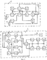
Сущность изобретения поясняется чертежом, где изображена блок-схема системы для дистанционного определения температуры воды водоемов.The invention is illustrated by the drawing, which shows a block diagram of a system for remote determination of the temperature of water in reservoirs.
Система состоит из передающих 1 и приемной станций 2.The system consists of transmitting 1 and receiving
Передающие станции 1 расположены в буях, установленных в различных участках водоема, а в случае необходимости в разных водоемах. Каждая станция 1 содержит два погружных датчика 3, 4 температуры, связанных с преобразователями 5, 6, двухвходовый коммутатор 7, аналого-цифровой преобразователь 8, передатчик 9, блок 10 окончания передачи сигналов, приемник 11 частотного запроса, блок питания 12, таймер 13, приемно-передающую антенну 14. При этом один датчик 3 расположен в верхнем слое воды, а второй 4 - в придонном. Выходы преобразователей 5, 6 связаны со входами двухвходового коммутатора 7, выход которого подключен ко входу аналого-цифрового преобразователя 8, выход которого связан со входом передатчика 9 сигналов, одним из выходов связанного с блоком 10 окончания передачи сигналов, а другим - с приемно-передающей антенной 14, дополнительно связанной через приемник 11 частотного запроса с блоком 10 окончания передачи сигналов. Питание всех элементов передающей станции осуществляется блоком питания 12 через приемник 11 частотного запроса и таймер 13.Transmitting
Приемная станция 2 установлена на берегу. Станция содержит приемно-передающую антенну 15, приемник 16 сигналов, схему запроса, блок 17 определения прихода сигналов, передатчик 18, модулятор 19, демодулятор 20, коммутатор 21, устройства для обработки данных и индикации результата измерения температуры верхнего и нижнего слоев воды водоема. Схема запроса содержит n параллельно соединенных генераторов 22 фиксированных частот (n - количество передающих станций), снабженных кнопками 23 запроса и подключенных к входу модулятора 19, выход которого через передатчик 18 подключен к приемно-передающей антенне 15. Приемно-передающая антенна 15 связана с входом приемника 16 сигналов, выход которого связан с входом демодулятора 20, подключенного к входу коммутатора 21, у которого один выход связан с устройством для обработки данных и индикации результата измерения температуры верхнего слоя воды водоема, а другой - с устройством для обработки данных и индикации результата измерения температуры нижнего слоя воды водоема. Каждое устройство для обработки данных и индикации результата измерения температуры содержит последовательно соединенные дешифратор 24, регистр памяти 25, цифровой индикатор 26 температуры. Блок питания 27 через тумблер 28 подключен к кнопкам 23 запроса схемы запроса, приемнику 16 сигналов и блоку 17 определения прихода сигналов непосредственно, а к остальным элементам схемы через приемник 16 сигналов и блок 17 определения прихода сигналов.
Система работает следующим образом:The system works as follows:
Перед вводом системы в эксплуатацию включают тумблеры питания передающих станций 1, и буи устанавливают в водоемы. Для запроса включают тумблер 28 блока 27 питания приемной станции 2. Питание поступает на схему запроса. Нажимают кнопку 23 запроса о состоянии температуры выбранной передающей станции 1. Генератор 22 подает частотный сигнал на модулятор 19, где сигнал модулируется несущей частотой и через передатчик 18 и приемно-передающую антенну 15 посылается в эфир, и принимается приемно-передающими антеннами 14 передающих станций 1. Сигнал запроса поступает на приемники 11 частотного запроса. Приемник 11 частотного запроса, настроенный на частоту поступившего сигнала, включает таймер 13 этой станции, который подключает питание ко всем элементам. Таймер 13 настроен на 5 секунд для предотвращения сбоя посылки данных во время запроса. Сигналы от датчиков 3, 4 температуры воды поверхности и дна водоема через преобразователи 5, 6 температуры поступают на входы коммутатора 7. При включении коммутатора 7 открывается его первый вход. Поступивший на этот вход сигнал от датчика 3 температуры воды поверхности водоема с выхода коммутатора 7 поступает на вход аналого-цифрового преобразователя 8, где преобразуется в цифровой сигнал, который поступает на вход передатчика 9 сигналов, который модулирует цифровую информацию несущей частотой, соответствующей данной передающей станции 1. Модулированный сигнал через передающую антенну 14 излучается в эфир. После этого коммутатор 7 переключается на второй вход. Время переключения входов коммутатора 7 установлено соответственно с периодом времени опроса текущего параметра. Поступивший на второй вход коммутатора 7 сигнал датчика температуры 4 воды дна водоема с выхода коммутатора 7 поступает на вход аналого-цифрового преобразователя 8, где преобразуется в цифровой сигнал, который поступает на вход передатчика 9 сигналов, который модулирует цифровую информацию несущей частотой, соответствующей данной передающей станции 1. После окончания передачи параметров температуры блок 10 окончания прохождения сигналов подает импульс на приемник 11 частотного запроса и переводит его в режим ожидания, отключая от питания элементы передающей станции.Before putting the system into operation, the power switches of the transmitting
Приемная станция 2 принимает сигнал, соответствующий температуре верхнего слоя воды водоема, от передающей станции 1 на приемно-передающую антенну 15, подающей сигнал на приемник 16. С первого выхода приемника 16 сигнал поступает на блок определения прихода сигналов, который включает питание всех элементов станции 2, а со второго выхода приемника 16 сигнал поступает на вход демодулятора 20, который срезает несущую частоту и выделяет сигнал, соответствующий передаваемому параметру (температуре). Сигнал поступает на вход коммутатора 21. Время срабатывания коммутаторов 7, 21 передающей и приемной станций одноименны. Открывается первый выход коммутатора 21, и сигнал поступает в устройство для обработки данных и индикации результата измерения температуры верхнего слоя воды водоема, где в дешифраторе 24 расшифровывается и поступает на вход регистра памяти 25, откуда сигнал записывается на индикатор 26 температуры поверхности водоема.The
Коммутатор 21 переходит на второе положение. Второй сигнал, соответствующий температуре нижнего слоя воды водоема, через приемно-передающую антенну 15, приемник 16, демодулятор 20, второй выход коммутатора 21 поступает в устройство для обработки данных и индикации результата измерения температуры нижнего слоя воды водоема, где через дешифратор 24, регистр 25 памяти расшифровывается в температуру нижнего слоя воды водоема и записывается на индикатор 26 температуры нижнего слоя воды водоема. После приема информации приемную станцию отключают с помощью тумблера 28. Для получения температурных параметров с другой передающей станции включают тумблер 28 приемной станции 2, нажимают кнопку 23 запроса нужной станции и подают соответствующий частотный сигнал запроса, который принимается передающей станцией 1, настроенной на эту частоту, станция 1 включается, снимает температурные параметры верхнего и нижнего слоя воды и передает их на приемную станцию 2, где фиксируется индикаторами 26 верхнего и нижнего слоев воды, и т.д.The
Предлагаемая система позволяет с одного диспетчерского пункта (приемной станции) запрашивать и получать температурные данные от разных водоемов и разных их мест. Система недорогая, простая в эксплуатации, энергоэкономичная, значительно облегчает труд сотрудников, следящих за гидрохимическим состоянием водоемов. Входящая в ее состав приемная станция малогабаритна, мобильна, может вручную переноситься на любое место.The proposed system allows you to request and receive temperature data from different water bodies and their different places from one control center (reception station). The system is inexpensive, easy to operate, energy efficient, greatly facilitates the work of employees who monitor the hydrochemical condition of water bodies. The receiving station included in its composition is small-sized, mobile, and can be manually transferred to any place.
Claims (1)
Priority Applications (1)
| Application Number | Priority Date | Filing Date | Title |
|---|---|---|---|
| RU2011142066/28A RU2477458C1 (en) | 2011-10-17 | 2011-10-17 | System for remote water temperature measurement of water reservoirs |
Applications Claiming Priority (1)
| Application Number | Priority Date | Filing Date | Title |
|---|---|---|---|
| RU2011142066/28A RU2477458C1 (en) | 2011-10-17 | 2011-10-17 | System for remote water temperature measurement of water reservoirs |
Publications (1)
| Publication Number | Publication Date |
|---|---|
| RU2477458C1 true RU2477458C1 (en) | 2013-03-10 |
Family
ID=49124260
Family Applications (1)
| Application Number | Title | Priority Date | Filing Date |
|---|---|---|---|
| RU2011142066/28A RU2477458C1 (en) | 2011-10-17 | 2011-10-17 | System for remote water temperature measurement of water reservoirs |
Country Status (1)
| Country | Link |
|---|---|
| RU (1) | RU2477458C1 (en) |
Citations (6)
| Publication number | Priority date | Publication date | Assignee | Title |
|---|---|---|---|---|
| SU140592A1 (en) * | 1958-03-10 | 1960-11-30 | А.К. Куклин | Open sea radio wave recorder |
| SU148259A1 (en) * | 1959-05-19 | 1961-11-30 | Ю.Ф. Васильев | A device for measuring the temperature of water in the sea on the go ship |
| SU1027532A1 (en) * | 1980-06-16 | 1983-07-07 | Специальное Конструкторское Бюро Радиофизического Приборостроения Научного Центра "Каспий" Ан Азсср | Device for taking temperature of water surface layer |
| RU1820237C (en) * | 1990-11-20 | 1993-06-07 | Центральный научно-исследовательский институт им.акад.А.Н.Крылова | Device for measuring temperature of water surface layer |
| US6568848B1 (en) * | 1999-09-20 | 2003-05-27 | Maverick Industries, Inc. | Wireless remote cooking thermometer system |
| EP1727106A1 (en) * | 2005-05-27 | 2006-11-29 | BRITISH TELECOMMUNICATIONS public limited company | Wireless telemetry |
-
2011
- 2011-10-17 RU RU2011142066/28A patent/RU2477458C1/en not_active IP Right Cessation
Patent Citations (6)
| Publication number | Priority date | Publication date | Assignee | Title |
|---|---|---|---|---|
| SU140592A1 (en) * | 1958-03-10 | 1960-11-30 | А.К. Куклин | Open sea radio wave recorder |
| SU148259A1 (en) * | 1959-05-19 | 1961-11-30 | Ю.Ф. Васильев | A device for measuring the temperature of water in the sea on the go ship |
| SU1027532A1 (en) * | 1980-06-16 | 1983-07-07 | Специальное Конструкторское Бюро Радиофизического Приборостроения Научного Центра "Каспий" Ан Азсср | Device for taking temperature of water surface layer |
| RU1820237C (en) * | 1990-11-20 | 1993-06-07 | Центральный научно-исследовательский институт им.акад.А.Н.Крылова | Device for measuring temperature of water surface layer |
| US6568848B1 (en) * | 1999-09-20 | 2003-05-27 | Maverick Industries, Inc. | Wireless remote cooking thermometer system |
| EP1727106A1 (en) * | 2005-05-27 | 2006-11-29 | BRITISH TELECOMMUNICATIONS public limited company | Wireless telemetry |
Similar Documents
| Publication | Publication Date | Title |
|---|---|---|
| CN101339200B (en) | An acoustic flow measurement method and device | |
| US7554884B2 (en) | Simplicity sonic depth finder for fishing | |
| JP2012525022A5 (en) | Reference signal arrangement method, channel information measurement method, base station apparatus and terminal apparatus | |
| CN104122558B (en) | Depth-sounding fish-finding system achieving display by means of mobile terminal and depth-sounding fish-finding method thereof | |
| RU2009133104A (en) | BASE STATION, USER DEVICE AND COMMUNICATION MANAGEMENT METHOD | |
| CN101523235A (en) | Nautical safety | |
| KR101131944B1 (en) | Vessel traffic system | |
| RU115929U1 (en) | HYDROACOUSTIC COMPLEX FOR REMOTE MONITORING OF HYDROPHYSICAL PARAMETERS IN SHALLOW WATER AQUATORIES | |
| WO2019084831A1 (en) | Portable marine beacon system | |
| CN107702698A (en) | A kind of deep-sea is against formula echo sounding system and measuring method | |
| CN104819742A (en) | A wireless monitoring device and method for ship-borne dangerous goods containers with underwater positioning function | |
| RU2013155557A (en) | TECHNOLOGICAL DEVICE LAUNCHED UNDER THE DISPLAY LIGHT LEVEL | |
| US20110304480A1 (en) | Apparatus for locating one mooring in a field of moorings | |
| KR101080178B1 (en) | Device and method for transmitting distress signal with Buoy | |
| RU2477458C1 (en) | System for remote water temperature measurement of water reservoirs | |
| CN202929801U (en) | Search and rescue terminal | |
| KR102206403B1 (en) | A transmitter for smart buoy, smart buoy and smart buoy system | |
| CN205080739U (en) | Recovery system is put to wireless sensor node cloth under water | |
| CN101282377A (en) | Device for prompting mobile phone signal | |
| CN203767030U (en) | Drifting buoy | |
| CN209182987U (en) | A kind of hydrometric cableway wireless digital transmission device | |
| RU2096247C1 (en) | Autonomous position station for depth sounding of water medium, method of determination of parameters of water medium and method of transmission of measured parameters | |
| KR20140017821A (en) | Network system for information transmitting and receiving using oceanographic unmanned observation | |
| CN202217049U (en) | Maritime Emergency Position Indicating System | |
| JP2009222465A (en) | Position detection system |
Legal Events
| Date | Code | Title | Description |
|---|---|---|---|
| MM4A | The patent is invalid due to non-payment of fees |
Effective date: 20141018 |