RU2476799C2 - Heat exchanger - Google Patents
Heat exchanger Download PDFInfo
- Publication number
- RU2476799C2 RU2476799C2 RU2009101457/06A RU2009101457A RU2476799C2 RU 2476799 C2 RU2476799 C2 RU 2476799C2 RU 2009101457/06 A RU2009101457/06 A RU 2009101457/06A RU 2009101457 A RU2009101457 A RU 2009101457A RU 2476799 C2 RU2476799 C2 RU 2476799C2
- Authority
- RU
- Russia
- Prior art keywords
- heat exchanger
- twisted
- ventilation circuit
- pipeline
- exchanger according
- Prior art date
Links
Images

Classifications
-
- F—MECHANICAL ENGINEERING; LIGHTING; HEATING; WEAPONS; BLASTING
- F28—HEAT EXCHANGE IN GENERAL
- F28D—HEAT-EXCHANGE APPARATUS, NOT PROVIDED FOR IN ANOTHER SUBCLASS, IN WHICH THE HEAT-EXCHANGE MEDIA DO NOT COME INTO DIRECT CONTACT
- F28D1/00—Heat-exchange apparatus having stationary conduit assemblies for one heat-exchange medium only, the media being in contact with different sides of the conduit wall, in which the other heat-exchange medium is a large body of fluid, e.g. domestic or motor car radiators
- F28D1/02—Heat-exchange apparatus having stationary conduit assemblies for one heat-exchange medium only, the media being in contact with different sides of the conduit wall, in which the other heat-exchange medium is a large body of fluid, e.g. domestic or motor car radiators with heat-exchange conduits immersed in the body of fluid
- F28D1/04—Heat-exchange apparatus having stationary conduit assemblies for one heat-exchange medium only, the media being in contact with different sides of the conduit wall, in which the other heat-exchange medium is a large body of fluid, e.g. domestic or motor car radiators with heat-exchange conduits immersed in the body of fluid with tubular conduits
- F28D1/047—Heat-exchange apparatus having stationary conduit assemblies for one heat-exchange medium only, the media being in contact with different sides of the conduit wall, in which the other heat-exchange medium is a large body of fluid, e.g. domestic or motor car radiators with heat-exchange conduits immersed in the body of fluid with tubular conduits the conduits being bent, e.g. in a serpentine or zig-zag
- F28D1/0472—Heat-exchange apparatus having stationary conduit assemblies for one heat-exchange medium only, the media being in contact with different sides of the conduit wall, in which the other heat-exchange medium is a large body of fluid, e.g. domestic or motor car radiators with heat-exchange conduits immersed in the body of fluid with tubular conduits the conduits being bent, e.g. in a serpentine or zig-zag the conduits being helically or spirally coiled
- F28D1/0473—Heat-exchange apparatus having stationary conduit assemblies for one heat-exchange medium only, the media being in contact with different sides of the conduit wall, in which the other heat-exchange medium is a large body of fluid, e.g. domestic or motor car radiators with heat-exchange conduits immersed in the body of fluid with tubular conduits the conduits being bent, e.g. in a serpentine or zig-zag the conduits being helically or spirally coiled the conduits having a non-circular cross-section
-
- F—MECHANICAL ENGINEERING; LIGHTING; HEATING; WEAPONS; BLASTING
- F28—HEAT EXCHANGE IN GENERAL
- F28D—HEAT-EXCHANGE APPARATUS, NOT PROVIDED FOR IN ANOTHER SUBCLASS, IN WHICH THE HEAT-EXCHANGE MEDIA DO NOT COME INTO DIRECT CONTACT
- F28D7/00—Heat-exchange apparatus having stationary tubular conduit assemblies for both heat-exchange media, the media being in contact with different sides of a conduit wall
- F28D7/02—Heat-exchange apparatus having stationary tubular conduit assemblies for both heat-exchange media, the media being in contact with different sides of a conduit wall the conduits being helically coiled
- F28D7/024—Heat-exchange apparatus having stationary tubular conduit assemblies for both heat-exchange media, the media being in contact with different sides of a conduit wall the conduits being helically coiled the conduits of only one medium being helically coiled tubes, the coils having a cylindrical configuration
-
- F—MECHANICAL ENGINEERING; LIGHTING; HEATING; WEAPONS; BLASTING
- F28—HEAT EXCHANGE IN GENERAL
- F28F—DETAILS OF HEAT-EXCHANGE AND HEAT-TRANSFER APPARATUS, OF GENERAL APPLICATION
- F28F2265/00—Safety or protection arrangements; Arrangements for preventing malfunction
- F28F2265/18—Safety or protection arrangements; Arrangements for preventing malfunction for removing contaminants, e.g. for degassing
Abstract
Description
Изобретение соотносится с теплообменником, соответствующим широкому описанию патентной формулы 1.The invention relates to a heat exchanger corresponding to the broad description of
Теплообменник упомянутого ранее вида, который в соответствии с DE 20009560 состоит из витого трубопровода спирального типа, проводящего к теплообменнику жидкую рабочую среду, винтовой оси горизонтального направления и частей витого трубопровода, расположенных сверху и снизу от винтовой оси. На внешней окружности витого трубопровода теплообменника предусмотрены патрубки для подключения приточно-отточной циркуляции, которая служит не только для подачи и отвода рабочей среды теплообменника, но и для вентиляции. Данный теплообменник является частью отопительного котла; он огибает камеру горения с горелкой, из которой по направлению потока витого трубопровода отходит отработанный газ и отдает свое тепло жидкой рабочей среде теплообменника.A heat exchanger of the aforementioned type, which, in accordance with DE 20009560, consists of a spiral-type coiled tubing that conducts a liquid working medium to the heat-exchanger, a horizontal axis of the helical axis and parts of a coiled tubing located above and below the helical axis. On the outer circumference of the twisted pipe of the heat exchanger, nozzles are provided for connecting the supply and exhaust circulation, which serves not only to supply and discharge the working medium of the heat exchanger, but also for ventilation. This heat exchanger is part of a boiler; it goes around the combustion chamber with a burner, from which the exhaust gas leaves in the direction of the flow of the twisted pipeline and gives its heat to the liquid working medium of the heat exchanger.
Основная задача изобретения сводится к тому, чтобы обеспечить теплообменник с трубопроводом витого типа и горизонтальной винтовой осью максимально возможной вентиляцией вне зависимости от оснащения теплообменника описанными выше патрубками для подключения приточно-отточной циркуляции.The main objective of the invention is to provide a heat exchanger with a twisted-type pipe and a horizontal screw axis with the maximum possible ventilation, regardless of the equipment of the heat exchanger with the above-described nozzles for connecting the supply and exhaust circulation.
Данная задача в отношении теплообменника первоначально указанного вида решается посредством характеристик, которые представлены в приведенных в патентной формуле 1 свойствах. При этом следует учитывать, что соответствующий изобретению теплообменник не ограничивается применением в отопительном котле, но также может быть установлен и в емкостных водонагревателях (в данном случае теплообменник окружен не отходящим газом горелки, а омывается подогреваемой водой), в которых равным образом может возникать проблема ухудшения теплообмена вследствие подачи газа.This problem in relation to the heat exchanger of the originally specified type is solved by the characteristics that are presented in the properties given in
Таким образом, изобретение предполагает, что контур протекания витого трубопровода обнаруживает два контура протекания, первый из которых имеет большие размеры и предусмотрен для рабочей среды теплообменника, а второй меньший контур протекания спиральной формы спроектирован для обеспечения вентиляции, причем для каждого спирального прохода в области описанной выше винтовой оси на витом трубопроводе имеется, как минимум, по одному отверстию для выпуска воздуха, которые связывают между собой первый и второй контуры протекания.Thus, the invention assumes that the flow path of the twisted pipeline detects two flow paths, the first of which is large and designed for the working environment of the heat exchanger, and the second smaller spiral flow path is designed to provide ventilation, and for each spiral passage in the region described above the screw axis on the twisted pipe has at least one air outlet that connects the first and second flow paths.
При этом условие «двухсекционного контура протекания» обеспечивает не только техническую возможность принципиально цельного витого трубопровода с двумя камерами протекания, но и функцию последующего внедрения в витой трубопровод дополнительных конструктивных элементов. Другими словами, если при таком варианте в витой трубопровод устанавливается дополнительный витой трубопровод (вентиляционный контур), то скапливающийся воздух или газ теоретически будут удаляться через предусмотренное преимущественно в верхней области каждого контура отверстие для выпуска воздуха.At the same time, the condition of a “two-section flow path” provides not only the technical feasibility of a fundamentally integral twisted pipeline with two flow chambers, but also the function of the subsequent introduction of additional structural elements into the twisted pipeline. In other words, if with this option an additional twisted pipe (ventilation circuit) is installed in the twisted pipeline, the accumulated air or gas will theoretically be removed through the air outlet provided primarily in the upper region of each circuit.
Для лучшего понимания изобретения необходимо учитывать следующее: в теплообменниках с трубопроводами витой формы и горизонтальной винтовой осью принципиальная проблема сводится к тому, что газ, поступающий в теплообменник с рабочей средой, по условиям гравитации скапливается в верхней области витого трубопровода, что является нежелательным, т.к. способствует ухудшению теплообмена. Конструкция теплообменника, выполненная в соответствии с DE 20009560 U1, предполагает, что на каждом втором контуре имеется патрубок, через который этот газ может быть удален (газ скапливается в контурах протекания в любом случае, даже при отсутствии таких патрубков). В теплообменниках, в которых подобные патрубки не предусмотрены, например, соответствующих ЕР 1562006 А1, проблематичность такого явления напрямую зависит от размера конструкции.For a better understanding of the invention, it is necessary to consider the following: in heat exchangers with twisted-shaped pipelines and a horizontal helical axis, the fundamental problem is that the gas entering the heat exchanger with the working medium accumulates in the upper region of the twisted pipeline under gravity conditions, which is undesirable, i.e. to. contributes to the deterioration of heat transfer. The design of the heat exchanger, made in accordance with DE 20009560 U1, assumes that on every second circuit there is a nozzle through which this gas can be removed (gas accumulates in the flow paths in any case, even in the absence of such nozzles). In heat exchangers in which such pipes are not provided, for example, corresponding to EP 1562006 A1, the problematic nature of this phenomenon directly depends on the size of the structure.
Настоящее изобретение решает данную проблему, т.к. обеспечивает возможность удаления газа именно в тех местах, где он скапливается, т.е. предусматривает в этих местах, как минимум, по одному отверстию для выпуска воздуха, через которые можно отводить газ.The present invention solves this problem, because provides the ability to remove gas precisely in those places where it accumulates, i.e. provides in these places at least one opening for the release of air through which gas can be vented.
Помимо того, что вентиляционный контур по плоскости сечения должен быть меньше витого трубопровода, данное условие предполагает, что вентиляционные отверстия, во-первых, должны быть расположены в трубопроводе определенным образом, и, во-вторых, способствовать устранению, прежде всего, газа и мелких частиц из рабочей среды теплообменника. Это условие более подробно описывается далее. Усовершенствованные варианты теплообменника согласно данному изобретению раскрыты в соответствующих зависимых пунктах формулы.In addition to the fact that the ventilation circuit along the section plane must be smaller than the twisted pipeline, this condition assumes that the ventilation holes, firstly, must be located in the pipeline in a certain way, and, secondly, help to eliminate, first of all, gas and small particles from the working environment of the heat exchanger. This condition is described in more detail below. Improved variants of the heat exchanger according to this invention are disclosed in the respective dependent claims.
Теплообменник, отвечающий условиям изобретения, а также его усовершенствованные варианты, описанные в формуле изобретения, детально показаны на следующих графических рисунках различных вариантов исполнения:A heat exchanger that meets the conditions of the invention, as well as its improved options described in the claims, are shown in detail in the following graphic drawings of various embodiments:
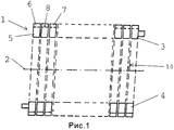
рис.1 - схематичное изображение первого конструктивного исполнения теплообменника, соответствующего настоящему изобретению, в продольном сечении;Fig. 1 is a schematic representation of a first embodiment of a heat exchanger according to the present invention in longitudinal section;
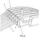
рис.2 - перспективное частичное изображение предпочтительной формы исполнения вентиляционного контура на витом трубопроводе со специальными выступами;Fig. 2 - perspective partial image of the preferred form of the ventilation circuit on a twisted pipe with special protrusions;
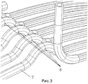
рис.3 - перспективное частичное изображение вентиляционного контура, соответствующего рис.3, без витого трубопровода; и рис.4 - перспективное изображение вентиляционного контура, как отдельного конструктивного элемента.Fig. 3 - perspective partial image of the ventilation circuit corresponding to Fig. 3, without a twisted pipeline; and Fig. 4 is a perspective image of the ventilation circuit as a separate structural element.
На рис.1 изображена абстрактная форма исполнения теплообменника, соответствующего настоящему изобретению, который состоит (данное пояснение также соотносится с конструктивными формами исполнения, представленными на рисунках 2-4) из витого трубопровода 1, проводящего к теплообменнику жидкую рабочую среду, который обнаруживает прямоугольный контур протекания, винтовой оси 2 горизонтального направления и частей витого трубопровода 3 и 4, которые расположены сверху и снизу от винтовой оси 2. При этом витой трубопровод имеет спиралевидную форму. В случае если трубопровод применяется в качестве теплообменника для отопительного котла, на нем предусматривается прорезь для протекания 10 (показано заштрихованным контуром), через которую протекает горячий отработанный газ горелки и тем самым подогревает рабочую среду теплообменника в витом трубопроводе.Fig. 1 shows an abstract embodiment of a heat exchanger in accordance with the present invention, which consists (this explanation also relates to the structural forms of execution shown in Figs. 2-4) of a
Существенным признаком теплообменника, соответствующего условиям настоящего изобретения, является тот факт, что витой трубопровод 1 имеет двухсекционный контур протекания, причем первый контур протекания 5, имеющий большие размеры, предусмотрен для рабочей среды теплообменника, а второй меньший контур протекания 6 спроектирован как вентиляционный контур (система) 7. При этом для каждого спирального прохода в области описанной выше винтовой оси 2 на части витого трубопровода 3 предусмотрено, как минимум, одно отверстие для выпуска воздуха 8, которое связывает между собой первый и второй контуры протекания 5 и 6.An essential feature of a heat exchanger corresponding to the conditions of the present invention is the fact that the
Повторная отсылка к рис.1 свидетельствует о том, что теплообменник представляет собой (как и предполагалось ранее теоретически) принципиально цельную конструкцию с двумя контурами протекания. В данном случае отверстия для выпуска воздуха 8 могут быть выполнены, например, путем двойного сверления витого трубопровода и последующей сварки внешнего отверстия.A repeated reference to Fig. 1 indicates that the heat exchanger is (as theoretically previously assumed) a fundamentally integral design with two flow paths. In this case, the
Однако более предпочтительным с технологической точки зрения представляется решение, соответствующее рис.2-4, которое предполагает исполнение вентиляционного контура 7 в качестве отдельного конструктивного элемента с последующей установкой в витой трубопровод, причем под «установкой» в частности подразумевается штопорообразное «ввинчивание» или «ввертывание» выполненного вентиляционного контура 7 спиралевидной формы в витой трубопровод 1.However, from a technological point of view, the solution corresponding to Fig. 2-4, which involves the execution of the
Для того, чтобы через вентиляционный контур 7 устранялось как можно меньше рабочей среды теплообменника, площадь поперечного сечения отверстия для выпуска воздуха 8 должна быть меньше контура протекания 6 вентиляционной системы 7. Кроме того, поскольку контур протекания 5 для рабочей среды теплообменника больше контура протекания 6 вентиляционной системы 7, соответственно площадь поперечного сечения отверстия для выпуска воздуха 8 должна быть намного меньше контура протекания 5 для рабочей среды теплообменника. Данное условие обуславливает перепад давления внутри теплообменника, что, во-первых, обеспечивает хорошую вентиляцию, а во-вторых, приводит к весьма незначительным потерям рабочей среды теплообменника через вентиляционный контур.In order to eliminate as little as possible the working medium of the heat exchanger through the
Наиболее предпочтительное технологическое решение предусматривает круглую форму контура протекания 6 вентиляционной системы 7 и круговое сечение отверстия для выпуска воздуха 8. Разумеется, для вентиляционного контура 7 также можно использовать другие профили (например, прямоугольные) и формы отверстия для выпуска воздуха 8 (например, щелевые). Очевидно, что трубчатый контур с простым отверстием или несколькими отверстиями более прост в изготовлении.The most preferred technological solution provides for the circular shape of the
С целью обеспечения более надежного положения вентиляционного контура 7 внутри витого трубопровода 1 предполагается (см. рис.4), что выполненный в спиралевидной форме вентиляционный контур 7 предпочтительно должен выступать на три радиуса и внутри витого трубопровода 1 опираться на выступы 9. При этом определяемые с учетом выступов 9 внешние диаметры вентиляционного контура 7 примерно соответствуют внутреннему диаметру контура протекания 5 для рабочей среды теплообменника, т.е. после ввинчивания вентиляционный контур 7 должен упруго подпираться внутренними стенками витого трубопровода 1 для постоянного обеспечения безопасного положения вентиляционного контура 7 внутри витого трубопровода 1, что особенно важно применительно к положению отверстия для выпуска воздуха 8, т.к. вентиляция теплообменника лучше всего функционирует тогда, когда отверстие для выпуска воздуха 8 находится в самом верху внутри витого трубопровода 1. В связи с этим, предпочтительнее в верхней области верхней части витого трубопровода 3 расположить один из выступов 9, на котором должно быть предусмотрено отверстие для выпуска воздуха 8 (см. рис.2 и 3).In order to ensure a more reliable position of the
Отвечающий требованиям изобретения теплообменник, а именно техническое оснащение теплообменника, соответствующее условиям изобретения, функционирует следующим образом:The heat exchanger that meets the requirements of the invention, namely the technical equipment of the heat exchanger, corresponding to the conditions of the invention, operates as follows:
рассмотрим, например, новую установку отопительного котла с теплообменником горизонтальной ориентации. Поступающий с рабочей средой теплообменника растворенный газ (в частности, воздух) по условиям гравитации скапливается в верхней точке витого трубопровода 1. Однако в связи с тем, что именно в этой точке предусмотрен вентиляционный контур 7 с отверстием для выпуска воздуха 8, этот газ может быть удален через вентиляционный контур 7, который хотя бы временно (например, с помощью клапана быстрого выхлопа) соединяется с окружающей средой теплообменника. Другими словами, благодаря давлению в теплообменнике избыточный газ удаляется из теплообменника через отверстие для выпуска воздуха 8 и вентиляционный контур 7, устраняя причины, препятствующие процессу теплообмена. В противоположность известным способам удаления газа из горизонтально расположенного теплообменника (как правило, вследствие высокой пропускной способности теплообменника) теплообменник, отвечающий условиям настоящего изобретения, отличается наличием во всех контурах ввинченной вентиляционной системы с внешними отверстиями, обеспечивающими эффективное прохождение воздуха, причем подобное удаление воздуха может осуществляться, как при запуске теплообменника в эксплуатацию, так и повторно в любой момент после него.consider, for example, a new installation of a heating boiler with a horizontal orientation heat exchanger. Dissolved gas entering the working medium of the heat exchanger (in particular, air) accumulates under the conditions of gravity at the upper point of the
Наконец, настоящее изобретение предусматривает соответствующее отведение обоих концов вентиляционного контура из витого трубопровода 1. Для этого (см. рис.2) может применяться, например, крышка (на рисунке не показана), которая будет закрывать витой трубопровод и одно из отверстий контура вентиляционной системы. При этом необходимо пояснить, что исполнение вентиляционного контура согласно рис.2, по меньшей мере, первоначально, должно быть выполнено с учетом возможности беспрепятственного свинчивания. Кроме того, канал для прохождения воздуха, как минимум, одной стороной вентиляционного контура должен быть открыт для среды (например, рабочей среды теплообменника), которая обеспечит минимальный уровень давления.Finally, the present invention provides for the appropriate removal of both ends of the ventilation circuit from the
Перечень отсылочных позицийList of reference items
1 Витой трубопровод1 Twisted pipe
2 Винтовая ось2 screw axis
3 Часть витого трубопровода3 Part of a twisted pipeline
4 Часть витого трубопровода4 Part of a twisted pipeline
5 Первый контур протекания5 First flow path
6 Второй контур протекания6 Second flow path
7 Вентиляционный контур (система)7 Ventilation circuit (system)
8 Отверстие для выпуска воздуха8 Air outlet
9 Выступ9 Projection
10 Прорезь для протекания.10 Slot for leakage.
Claims (9)
Applications Claiming Priority (2)
| Application Number | Priority Date | Filing Date | Title |
|---|---|---|---|
| DE102008008734A DE102008008734A1 (en) | 2008-02-12 | 2008-02-12 | heat exchangers |
| DE2008008734.3 | 2008-02-12 |
Publications (2)
| Publication Number | Publication Date |
|---|---|
| RU2009101457A RU2009101457A (en) | 2010-07-27 |
| RU2476799C2 true RU2476799C2 (en) | 2013-02-27 |
Family
ID=40467033
Family Applications (1)
| Application Number | Title | Priority Date | Filing Date |
|---|---|---|---|
| RU2009101457/06A RU2476799C2 (en) | 2008-02-12 | 2009-01-20 | Heat exchanger |
Country Status (9)
| Country | Link |
|---|---|
| EP (1) | EP2090858B1 (en) |
| AT (1) | ATE463709T1 (en) |
| DE (2) | DE102008008734A1 (en) |
| DK (1) | DK2090858T3 (en) |
| ES (1) | ES2341507T3 (en) |
| HR (1) | HRP20100367T1 (en) |
| PL (1) | PL2090858T3 (en) |
| RU (1) | RU2476799C2 (en) |
| SI (1) | SI2090858T1 (en) |
Families Citing this family (1)
| Publication number | Priority date | Publication date | Assignee | Title |
|---|---|---|---|---|
| DE102011010444A1 (en) * | 2011-02-04 | 2012-08-09 | Viessmann Werke Gmbh & Co Kg | Heating boiler has coil tube having coil tube ends for hydraulically connecting coil tube portions to supply and discharge ports and terminating hydraulic connection of coil tube portions respectively |
Citations (4)
| Publication number | Priority date | Publication date | Assignee | Title |
|---|---|---|---|---|
| SU494586A1 (en) * | 1974-02-06 | 1975-12-05 | Ордена Трудового Красного Знамени Предприятие П/Я А-1665 | Ring heat exchanger |
| RU2080536C1 (en) * | 1994-01-12 | 1997-05-27 | Тамбовское акционерное общество открытого типа "Комсомолец" | Heat exchanger |
| DE20009560U1 (en) * | 2000-05-27 | 2000-09-28 | Viessmann Werke Kg | Heat exchanger |
| EP1562006B1 (en) * | 2004-01-30 | 2007-08-01 | Viessmann Werke GmbH & Co KG | Heating device |
Family Cites Families (4)
| Publication number | Priority date | Publication date | Assignee | Title |
|---|---|---|---|---|
| DE3315258A1 (en) * | 1983-04-27 | 1984-10-31 | Etablissement Agura, Vaduz | Spiral ring heating boiler |
| FR2550615B1 (en) * | 1983-08-12 | 1985-12-06 | Fonderie Soc Gen De | SERPENTINE EXCHANGER BOILER |
| DE10106371A1 (en) * | 2001-02-12 | 2002-08-14 | Ludwig Pilsl | Arrangement, for exchanging heat, has tubes combined to form flat mechanical unit by a joint with good thermal conductivity with common outer wall forming heat exchange surface |
| CA2573082A1 (en) * | 2004-07-09 | 2006-01-19 | Junjie Gu | Refrigeration system |
-
2008
- 2008-02-12 DE DE102008008734A patent/DE102008008734A1/en not_active Withdrawn
-
2009
- 2009-01-20 RU RU2009101457/06A patent/RU2476799C2/en not_active IP Right Cessation
- 2009-02-03 SI SI200930002T patent/SI2090858T1/en unknown
- 2009-02-03 EP EP09001426A patent/EP2090858B1/en active Active
- 2009-02-03 DK DK09001426.7T patent/DK2090858T3/en active
- 2009-02-03 PL PL09001426T patent/PL2090858T3/en unknown
- 2009-02-03 AT AT09001426T patent/ATE463709T1/en active
- 2009-02-03 ES ES09001426T patent/ES2341507T3/en active Active
- 2009-02-03 DE DE502009000007T patent/DE502009000007D1/en active Active
-
2010
- 2010-06-29 HR HR20100367T patent/HRP20100367T1/en unknown
Patent Citations (4)
| Publication number | Priority date | Publication date | Assignee | Title |
|---|---|---|---|---|
| SU494586A1 (en) * | 1974-02-06 | 1975-12-05 | Ордена Трудового Красного Знамени Предприятие П/Я А-1665 | Ring heat exchanger |
| RU2080536C1 (en) * | 1994-01-12 | 1997-05-27 | Тамбовское акционерное общество открытого типа "Комсомолец" | Heat exchanger |
| DE20009560U1 (en) * | 2000-05-27 | 2000-09-28 | Viessmann Werke Kg | Heat exchanger |
| EP1562006B1 (en) * | 2004-01-30 | 2007-08-01 | Viessmann Werke GmbH & Co KG | Heating device |
Also Published As
| Publication number | Publication date |
|---|---|
| EP2090858B1 (en) | 2010-04-07 |
| RU2009101457A (en) | 2010-07-27 |
| DK2090858T3 (en) | 2010-07-05 |
| SI2090858T1 (en) | 2010-07-30 |
| DE102008008734A1 (en) | 2009-08-13 |
| ES2341507T3 (en) | 2010-06-21 |
| HRP20100367T1 (en) | 2010-10-31 |
| PL2090858T3 (en) | 2010-07-30 |
| EP2090858A1 (en) | 2009-08-19 |
| DE502009000007D1 (en) | 2010-05-20 |
| ATE463709T1 (en) | 2010-04-15 |
Similar Documents
| Publication | Publication Date | Title |
|---|---|---|
| CN204787951U (en) | Formula of backflowing sleeve pipe evaporimeter | |
| RU2602947C1 (en) | Condensation heat exchanger with false tubes | |
| JP4470790B2 (en) | Reverse combustion water heater | |
| CN204787943U (en) | U jacket tube -type evaporator | |
| RU2440538C1 (en) | Outside condensation boiler | |
| RU2674850C2 (en) | Tube for heat exchanger with at least partially variable cross-section and heat exchanger equipped therewith | |
| RU2476799C2 (en) | Heat exchanger | |
| CN101166380B (en) | A tube type heater for electric water heater | |
| JP5790973B2 (en) | Water heater | |
| CN203432412U (en) | Condensing device with self-cleaning function | |
| KR20120015898A (en) | Small boiler waste heat recycle apparatus | |
| JP2007298245A (en) | Economizer and exhaust heat recovery boiler provided therewith | |
| CN110220407B (en) | Condensation heat exchanger with self-purification function | |
| JP2021162296A (en) | Boiler flue gas recovery heater | |
| KR20210039191A (en) | Heat Recovery System for Boiler | |
| KR20080105486A (en) | Air and water separator for boilers | |
| RU2333432C1 (en) | Condensation universal water-heating installation of external accommodation | |
| KR100632128B1 (en) | An associated boiler | |
| JP2014214924A (en) | Latent heat exchanger | |
| KR101604536B1 (en) | Haet exchanger for heat pump | |
| JP6125321B2 (en) | Boiler with feed water preheater | |
| KR200464650Y1 (en) | Uptrend Combustion Typed Condensing Boiler | |
| KR20190128830A (en) | Heat Recovery System for Boiler | |
| KR100746385B1 (en) | The heating device using the waste gas heat of the boiler pipe | |
| KR200435897Y1 (en) | A boiler |
Legal Events
| Date | Code | Title | Description |
|---|---|---|---|
| MM4A | The patent is invalid due to non-payment of fees |
Effective date: 20180121 |