RU2476183C2 - Device for implant removal - Google Patents
Device for implant removal Download PDFInfo
- Publication number
- RU2476183C2 RU2476183C2 RU2011101940/14A RU2011101940A RU2476183C2 RU 2476183 C2 RU2476183 C2 RU 2476183C2 RU 2011101940/14 A RU2011101940/14 A RU 2011101940/14A RU 2011101940 A RU2011101940 A RU 2011101940A RU 2476183 C2 RU2476183 C2 RU 2476183C2
- Authority
- RU
- Russia
- Prior art keywords
- implant
- threaded
- removal device
- channel
- bone
- Prior art date
Links
Images


Classifications
-
- A—HUMAN NECESSITIES
- A61—MEDICAL OR VETERINARY SCIENCE; HYGIENE
- A61C—DENTISTRY; APPARATUS OR METHODS FOR ORAL OR DENTAL HYGIENE
- A61C8/00—Means to be fixed to the jaw-bone for consolidating natural teeth or for fixing dental prostheses thereon; Dental implants; Implanting tools
-
- A—HUMAN NECESSITIES
- A61—MEDICAL OR VETERINARY SCIENCE; HYGIENE
- A61C—DENTISTRY; APPARATUS OR METHODS FOR ORAL OR DENTAL HYGIENE
- A61C8/00—Means to be fixed to the jaw-bone for consolidating natural teeth or for fixing dental prostheses thereon; Dental implants; Implanting tools
- A61C8/0089—Implanting tools or instruments
-
- A—HUMAN NECESSITIES
- A61—MEDICAL OR VETERINARY SCIENCE; HYGIENE
- A61C—DENTISTRY; APPARATUS OR METHODS FOR ORAL OR DENTAL HYGIENE
- A61C3/00—Dental tools or instruments
-
- A—HUMAN NECESSITIES
- A61—MEDICAL OR VETERINARY SCIENCE; HYGIENE
- A61C—DENTISTRY; APPARATUS OR METHODS FOR ORAL OR DENTAL HYGIENE
- A61C3/00—Dental tools or instruments
- A61C3/14—Dentists' forceps or the like for extracting teeth
-
- A—HUMAN NECESSITIES
- A61—MEDICAL OR VETERINARY SCIENCE; HYGIENE
- A61C—DENTISTRY; APPARATUS OR METHODS FOR ORAL OR DENTAL HYGIENE
- A61C8/00—Means to be fixed to the jaw-bone for consolidating natural teeth or for fixing dental prostheses thereon; Dental implants; Implanting tools
- A61C8/0018—Means to be fixed to the jaw-bone for consolidating natural teeth or for fixing dental prostheses thereon; Dental implants; Implanting tools characterised by the shape
- A61C8/0022—Self-screwing
Abstract
Description
ОБЛАСТЬ ТЕХНИКИFIELD OF TECHNOLOGY
Данное изобретение относится к устройству, которое дает возможность снимать имплантат с кости пациента, например, удалять зубной имплантат изо рта пациента после того, как данный зубной имплантат был вживлен внутрикостно в верхнюю челюсть или челюстную кость пациента.The present invention relates to a device that makes it possible to remove an implant from a patient’s bone, for example, to remove a dental implant from the patient’s mouth after the dental implant has been implanted intraosseously into the maxilla or jaw of the patient.
ИЗВЕСТНЫЙ УРОВЕНЬ ТЕХНИКИKNOWN LEVEL OF TECHNOLOGY
Имплантатом является изделие, которое устанавливается в костную полость, подготовленную в кости пациента, и к которому позднее крепится протез. Процедура установки имплантата обычно следующая: в кости пациента высверливается полость для вмещения имплантата; имплантат вставляется в данную полость; через определенный период времени имплантат вживляется внутри кости; после того, как имплантат внутрикостно вживлен, к имплантату может быть прикреплен протез с помощью винта или какой бы то ни было пригодной вспомогательной детали.An implant is a product that is inserted into a bone cavity prepared in a patient’s bone, and to which a prosthesis is later attached. The implant placement procedure is usually as follows: a cavity is drilled into the patient’s bone to accommodate the implant; the implant is inserted into this cavity; after a certain period of time, the implant is implanted inside the bone; after the implant has been implanted intraosseously, the prosthesis can be attached to the implant using a screw or any suitable accessory.
К сожалению, иногда необходимо удалить имплантат после того, как он был установлен и вживлен. Например, требуется удалить имплантат в случае непредусмотренного костного ущерба, разлома кости либо если имплантат был установлен неправильно. Имплантат также должен быть удален при модифицировании протеза, когда имплантат более не является эффективным или необходимым для крепления протеза.Unfortunately, sometimes it is necessary to remove the implant after it has been installed and implanted. For example, you need to remove the implant in case of unintended bone damage, fracture of the bone, or if the implant was not installed correctly. The implant must also be removed when modifying the prosthesis, when the implant is no longer effective or necessary to secure the prosthesis.
Удаление имплантата является нелегкой задачей, поскольку он сконструирован так, что его соединение с костью чрезвычайно прочно, устойчиво к многонаправленным силам и его трудно разрушить. Например, в зубной имплантологии, зубной имплантат должен противостоять многократным окклюзивным и жевательным усилиям величиной до 700 Н в течение срока его службы.Removing the implant is not an easy task because it is designed so that its connection with the bone is extremely strong, resistant to multidirectional forces and difficult to break. For example, in dental implantology, a dental implant must withstand repeated occlusive and chewing efforts of up to 700 N over its life.
В продолжение рассмотрения примера зубных имплантатов, самый часто используемый способ съема зубных имплантатов в настоящее время состоит в высверливании кости вокруг имплантата с помощью полого цилиндрического бора, который удаляет зубной имплантат вместе с частью окружающей костной ткани. Данный способ, очевидно, является травмирующим, поскольку он затрагивает удаление значительного объема костной ткани и оставляет большую полость в кости пациента. Данная полость затем должна быть заполнена и восстановлена с помощью соответствующих методик костной регенерации. Кроме того, данная полость может быть до 30% больше в диаметре, чем диаметр имплантата, что эквивалентно объему костной ткани, большему на 70%. Это означает, что потребуется установить второй имплантат гораздо большего размера, если снятый имплантат необходимо заменить.To continue examining the example of dental implants, the most commonly used method for removing dental implants currently consists of drilling a bone around the implant using a hollow cylindrical bur that removes the dental implant along with part of the surrounding bone tissue. This method, obviously, is traumatic, since it involves the removal of a significant amount of bone tissue and leaves a large cavity in the patient’s bone. This cavity should then be filled and restored using appropriate bone regeneration techniques. In addition, this cavity can be up to 30% larger in diameter than the diameter of the implant, which is equivalent to a 70% larger volume of bone tissue. This means that you will need to install a second implant of a much larger size if the removed implant needs to be replaced.
В большинстве случаев, съем любого имплантата является травмирующим.In most cases, removal of any implant is traumatic.
Задача данного изобретения состоит в том, чтобы предложить новый инструмент, который позволяет снимать имплантат, по возможности, наименее травмирующим образом для кости пациента, используя процедуру съема, выполнение которой является простым для хирурга и доставляет минимально возможный дискомфорт пациенту.The objective of this invention is to propose a new tool that allows you to remove the implant, if possible, the least traumatic way for the patient’s bone, using the removal procedure, which is simple for the surgeon and delivers the least possible discomfort to the patient.
КРАТКОЕ ОПИСАНИЕ ИЗОБРЕТЕНИЯSUMMARY OF THE INVENTION
Объектом данного изобретения является устройство, позволяющее удалять имплантат из кости пациента, причем имплантат отличается тем, что он содержит наружные стенки, находящиеся в контакте с костной тканью, и тем, что он содержит канал. Данный канал либо изначально предусматривается в имплантате, либо вырезается в нем перед применением устройства съема имплантата. Устройство съема имплантата содержит головную часть и рабочую часть, имеющую резьбу. Головная часть предусматривает средство прикрепления системы, способной обеспечить крутящий момент устройству съема имплантата, например, хирургического мотора, храпового ключа и т.д. Нарезная рабочая часть, предпочтительно, имеет уменьшающийся диаметр. В какой-то точке диаметр нарезной рабочей части больше диаметра канала имплантата; наименьший диаметр нарезной рабочей части меньше диаметра данного канала. Нарезная рабочая часть предназначена для введения в канал имплантата и ввинчивания (вдавливая резьбу) во внутренние стенки указанного канала. Нарезная рабочая часть имеет уменьшающийся диаметр, так что диаметр его конца меньше, чем канал имплантата, а остальная часть нарезной области увеличивается по толщине и может быть надлежащим образом прикреплена к внутренним стенкам канала (чего не происходит при постоянном диаметре).The object of this invention is a device that allows you to remove the implant from the patient’s bone, and the implant is characterized in that it contains external walls in contact with bone tissue, and that it contains a channel. This channel is either initially provided in the implant, or is cut out in it before using the implant removal device. The implant removal device comprises a head part and a working part having a thread. The head part provides means for attaching a system capable of providing torque to the implant removal device, for example, a surgical motor, ratchet wrench, etc. The threaded working part preferably has a decreasing diameter. At some point, the diameter of the threaded working part is larger than the diameter of the implant channel; the smallest diameter of the threaded working part is less than the diameter of this channel. The threaded working part is intended for insertion into the channel of the implant and screwing (pressing the thread) into the inner walls of the specified channel. The threaded working part has a decreasing diameter, so that the diameter of its end is smaller than the implant channel, and the rest of the threaded area increases in thickness and can be properly attached to the inner walls of the channel (which does not happen with a constant diameter).
Действие устройства съема имплантата следующее. Устройство съема имплантата вводится в канал имплантата (который может уже существовать либо может быть просверлен перед извлечением). Система, обеспечивающая крутящий момент, заставляет устройство съема имплантата вращаться. В то время, когда система, обеспечивающая крутящий момент, заставляет устройство съема имплантата вращаться, устройство съема имплантата ввинчивается в канал имплантата, вдавливая резьбу. По мере вращения системы, нарезная рабочая часть устройства съема имплантата уплотняет его прикрепление к каналу, так что к внешним стенкам имплантата, находящимся в контакте с костной тканью, прикладывается крутящий момент затяжки. Когда крутящий момент затяжки превышает определенное значение, вращение системы, обеспечивающей крутящий момент, заставляет имплантат разорвать его соединение с костью, позволяя его удалить.The operation of the implant removal device is as follows. An implant removal device is inserted into the implant channel (which may already exist or may be drilled before removal). The torque system causes the implant removal device to rotate. While the torque providing system causes the implant removal device to rotate, the implant removal device is screwed into the implant channel, pressing the thread. As the system rotates, the threaded working part of the implant removal device seals its attachment to the channel, so that a tightening torque is applied to the external walls of the implant in contact with the bone tissue. When the tightening torque exceeds a certain value, the rotation of the system providing the torque causes the implant to break its connection with the bone, allowing it to be removed.
Предпочтительно, нарезная рабочая часть устройства съема имплантата имеет левую резьбу, чтобы давать возможность оптимальной работы с имплантатами, у которых наружные стенки имеют резьбу (в силу чего резьба данной нарезной части является обычно правой). Другими словами, резьба нарезной рабочей части устройства съема имплантата направлена противоположно резьбе нарезной части большинства имплантатов, оснащенных нарезной частью (например, большинства зубных имплантатов). Данный вариант осуществления также будет возможно использовать для съема имплантатов, не снабженных внешней резьбой.Preferably, the threaded working portion of the implant removal device has a left-hand thread to enable optimal operation with implants in which the external walls are threaded (whereby the thread of this threaded portion is usually right). In other words, the thread of the threaded working part of the implant removal device is directed opposite to the thread of the threaded part of most implants equipped with a threaded part (for example, most dental implants). This embodiment will also be possible to use for removal of implants not provided with external thread.
Очевидно, что вариант осуществления, в котором нарезная рабочая часть устройства съема имплантата имеет правую резьбу, также рассматривается. Данный вариант осуществления, в основном, будет использоваться для съема имплантатов с левой наружной резьбой, хотя его также будет возможно использовать, например, для съема имплантатов, не снабженных внешней резьбой.Obviously, an embodiment in which a threaded working portion of an implant removal device has a right-hand thread is also considered. This embodiment will mainly be used to remove implants with a left external thread, although it will also be possible to use, for example, to remove implants that are not equipped with an external thread.
В данном случае, действие устройства съема имплантата следующее. Прежде всего, устройство съема имплантата вводится в канал имплантата. Система, обеспечивающая крутящий момент, заставляет устройство съема имплантата вращаться в направлении против часовой стрелки (налево). В то время, когда система, обеспечивающая крутящий момент, заставляет устройство съема имплантата вращаться, устройство съема имплантата ввинчивается в канал имплантата, вдавливая резьбу. По мере вращения системы, нарезная рабочая часть устройства съема имплантата уплотняет его прикрепление к каналу; в результате чего к нарезной части имплантата прикладывается крутящий момент затяжки. Когда крутящий момент затяжки превышает определенное значение, вращение системы, обеспечивающей крутящий момент, влево (против часовой стрелки) заставляет имплантат разорвать его соединение с костью и начинает вытаскивать имплантат (поскольку резьба его нарезной части направлена вправо). Если система продолжает вращаться влево, имплантат вынимается и аккуратно удаляется из костной ткани.In this case, the operation of the implant removal device is as follows. First of all, the implant removal device is inserted into the implant channel. The torque system causes the implant removal device to rotate in a counterclockwise direction (left). While the torque providing system causes the implant removal device to rotate, the implant removal device is screwed into the implant channel, pressing the thread. As the system rotates, the threaded working part of the implant removal device seals its attachment to the channel; as a result, a tightening torque is applied to the threaded portion of the implant. When the tightening torque exceeds a certain value, the rotation of the system that provides the torque to the left (counterclockwise) forces the implant to break its connection with the bone and begins to pull out the implant (since the thread of its threaded part is directed to the right). If the system continues to rotate to the left, the implant is removed and carefully removed from the bone tissue.
Имплантаты обычно оснащаются потайным отверстием, имеющим резьбу, с помощью которого крепятся различные компоненты, такие как винт, формирователь десны и т.п. В таком случае устройство съема имплантата, согласно данному изобретению, предпочтительно будет вводиться в данное потайное отверстие с резьбой.Implants are usually equipped with a secret hole that has a thread through which various components are attached, such as a screw, a healing abutment, etc. In such a case, the implant removal device according to the invention will preferably be inserted into the threaded secret hole.
Устройство съема имплантата, согласно данному изобретению, может использоваться для съема имплантатов многих типов: зубных имплантатов, винтов для остеосинтеза, полых имплантатов, винтов для крепления костного блока и др.The implant removal device according to this invention can be used to remove many types of implants: dental implants, screws for osteosynthesis, hollow implants, screws for fixing the bone block, etc.
В случае зубных имплантатов, хирургические исследования доказали, что устройство съема имплантата, согласно данному изобретению, позволяет снимать зубной имплантат почти идеальным образом (даже в случае съема зубных имплантатов с цилиндрическими и безрезьбовыми наружными стенками). С другой стороны, при использовании традиционных инструментов, процедура съема является значительно более сложной и опасной для пациента. Помимо того, что в кости образуется окончательная полость, которая гораздо больше (с учетом того вреда, который это может повлечь, как описано выше), но также процедура является рискованной. Если введение с помощью традиционного инструмента (трефинационного бора) слишком глубоко, то альвеолярный нерв или прилегающие имплантаты либо зубы могут быть повреждены. Данный риск не существует при использовании устройства, согласно настоящему изобретению.In the case of dental implants, surgical studies have proved that the implant removal device according to this invention allows the dental implant to be removed in an almost perfect way (even in the case of dental implants with cylindrical and threadless external walls). On the other hand, when using traditional tools, the removal procedure is much more complex and dangerous for the patient. In addition to the fact that the final cavity is formed in the bone, which is much larger (taking into account the harm that it can cause, as described above), but also the procedure is risky. If the introduction with a traditional instrument (trefination bur) is too deep, then the alveolar nerve or adjacent implants or teeth may be damaged. This risk does not exist when using the device according to the present invention.
Кроме того, устройство съема имплантата, согласно данному изобретению, дает возможность установить другой имплантат такого же размера, как предыдущий (который имеет предположительно наиболее приемлемый размер), в костную полость после съема имплантата. И, наоборот, если необходимо окончательное удаление имплантата, небольшой размер костной полости значительно улучшает ситуацию после извлечения, ощутимо сокращая время восстановления (период времени для полной регенерации кости).In addition, the implant removal device according to the invention makes it possible to insert another implant of the same size as the previous one (which is supposedly the most suitable size) into the bone cavity after removal of the implant. Conversely, if final implant removal is necessary, the small size of the bone cavity significantly improves the situation after extraction, significantly reducing the recovery time (the time period for complete bone regeneration).
КРАТКОЕ ОПИСАНИЕ ЧЕРТЕЖЕЙBRIEF DESCRIPTION OF THE DRAWINGS
Детали данного изобретения могут быть понятны из прилагаемых чертежей, которые не ограничивают объем данного изобретения.Details of the invention may be understood from the accompanying drawings, which do not limit the scope of the invention.
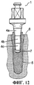
Фиг.1-4 иллюстрируют последовательность съема зубного имплантата с использованием первого варианта осуществления устройства съема имплантата, согласно данному изобретению.Figures 1-4 illustrate a dental implant removal sequence using the first embodiment of an implant removal device according to the present invention.
Фиг.5-8 иллюстрируют последовательность съема зубного имплантата с использованием второго варианта осуществления устройства съема имплантата, согласно данному изобретению.Figures 5-8 illustrate a dental implant removal sequence using a second embodiment of an implant removal device according to the present invention.
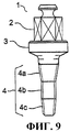
На Фиг.9 представлен другой вариант осуществления устройства съема имплантата, согласно данному изобретению.Fig. 9 shows another embodiment of an implant removal device according to the present invention.
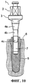
Фиг.10, 11, 12 иллюстрируют последовательность введения устройства съема имплантата, представленного на фиг.9, в зубной имплантат.10, 11, 12 illustrate the sequence of insertion of the implant removal device of FIG. 9 into a dental implant.
ПОДРОБНОЕ ОПИСАНИЕ ИЗОБРЕТЕНИЯDETAILED DESCRIPTION OF THE INVENTION
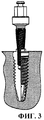
Фиг.1-4 иллюстрируют последовательность съема имплантата, в данном случае, зубного имплантата, с использованием первого варианта осуществления устройства (1) съема имплантата, согласно данному изобретению. Как видно из чертежей, имплантат (5) содержит часть (8), имеющую резьбу, и верхнюю часть (9). Нарезная часть (8) прикрепляет имплантат (5) к кости (6). Верхняя часть (9) дает возможность прикреплять имплантат (5) к протезу (искусственному зубу). Данные чертежи иллюстрируют имплантат (5), снабженный наружным соединением; другими словами, верхняя часть (9) имеет выступающий элемент, в данном случае, шестиугольный выступ (10), на который помещаются дополнительные компоненты для того, чтобы прикрепить протез. Имплантат (5) содержит канал (7), который на чертеже изображен в виде темного канала с резьбой, снабженного областью (12) с резьбой и цилиндрическим углублением (11).FIGS. 1-4 illustrate the implant removal sequence, in this case, the dental implant, using the first embodiment of the implant removal device (1) according to this invention. As can be seen from the drawings, the implant (5) contains a part (8) having a thread and an upper part (9). The threaded portion (8) attaches the implant (5) to the bone (6). The upper part (9) makes it possible to attach the implant (5) to the prosthesis (artificial tooth). These drawings illustrate an implant (5) provided with an external connection; in other words, the upper part (9) has a protruding element, in this case, a hexagonal protrusion (10), on which additional components are placed in order to attach the prosthesis. The implant (5) contains a channel (7), which is shown in the drawing as a dark threaded channel provided with a threaded area (12) and a cylindrical recess (11).
Устройство (1) съема имплантата содержит головную часть (2) и нарезную рабочую часть (4). Головная часть (2) служит средством прикрепления системы, способной обеспечить крутящий момент устройству (1) съема имплантата. Например, система, обеспечивающая крутящий момент, может представлять собой хирургический мотор, храповой ключ и т.д. Нарезная рабочая часть (4) должна вставляться в канал (7) имплантата (5) и скрепляться с имплантатом (5). Нарезная рабочая часть (4) имеет резьбовой профиль с уменьшающимся диаметром, который способен вдавливать свою резьбу во внутренние стенки канала (7) имплантата (5). Минимальный диаметр нарезной рабочей части (4), следовательно, должен быть меньше, чем диаметр канала (7). Резьба нарезной рабочей части (4) направлена налево, что противоположно направлению резьбы нарезной части (8) имплантата (5). Устройство (1) съема имплантата, представленное на данных чертежах, специально сконструировано для съема имплантата (5), снабженного наружным соединением: длинная нарезная рабочая часть (4), способная иметь резьбу как до цилиндрического углубления (11), так и до области (12) с резьбой канала (7) имплантата (5).The implant removal device (1) comprises a head part (2) and a threaded working part (4). The head part (2) serves as a means of attaching a system capable of providing torque to the implant removal device (1). For example, a torque system may be a surgical motor, ratchet wrench, etc. The threaded working part (4) must be inserted into the channel (7) of the implant (5) and fastened to the implant (5). The threaded working part (4) has a threaded profile with a decreasing diameter, which is able to press its thread into the inner walls of the implant channel (7) (5). The minimum diameter of the threaded working part (4), therefore, should be less than the diameter of the channel (7). The thread of the threaded working part (4) is directed to the left, which is opposite to the thread direction of the threaded part (8) of the implant (5). The implant removal device (1) shown in these drawings is specially designed for removal of the implant (5) equipped with an external connection: a long threaded working part (4) capable of having thread both to the cylindrical recess (11) and to the area (12 ) with the thread of the channel (7) of the implant (5).
Предпочтительно, устройство (1) съема имплантата также содержит среднюю часть (3), расположенную между головной частью (2) и рабочей частью (4), имеющей резьбу. Данная средняя часть (3) должна быть чрезвычайно прочной, для того чтобы не сломаться, когда система, обеспечивающая крутящий момент, вращает устройство (1) съема имплантата. Необходимо учитывать, что, при вращении, устройство (1) съема имплантата подвергается огромной нагрузке благодаря тому, что нарезная рабочая часть (4) становится скрепленной с каналом (7) и что имплантат (5) разрушает свое резьбовое соединение с костью (6).Preferably, the implant removal device (1) also comprises a middle part (3) located between the head part (2) and the working part (4) having a thread. This middle part (3) must be extremely strong so as not to break when the torque providing system rotates the implant removal device (1). It is necessary to take into account that, during rotation, the implant removal device (1) is subjected to a huge load due to the fact that the threaded working part (4) becomes attached to the channel (7) and that the implant (5) destroys its threaded connection with the bone (6).
Нарезная рабочая часть (4), предпочтительно, имеет коническую форму, для простоты изготовления (автоматизированного). Однако данное изобретение рассматривает другие различные варианты осуществления, в которых профиль нарезной рабочей части (4) сужается либо нет.The threaded working part (4) preferably has a conical shape, for ease of manufacture (automated). However, the present invention contemplates various other embodiments in which the profile of the threaded working portion (4) is narrowed or not.
Действие устройства (1) съема имплантата следующее. Как видно из фиг.1 и 2, устройство (1) съема имплантата вводится в канал (7) имплантата (5). Изначально между устройством (1) съема имплантата и каналом (7) есть определенный зазор, как можно видеть на фиг.2. Когда устройство (1) съема имплантата достигает лимита (зазор исчезает), система, обеспечивающая крутящий момент, приводится в действие так, что она вращается влево (в направлении против часовой стрелки). Затем устройство (1) съема имплантата начинает ввинчиваться (вдавливая резьбу) в цилиндрическое углубление (11) и в область (12) с резьбой, как представлено на фиг.3. Если система, обеспечивающая крутящий момент, продолжает вращение, то устройство (1) съема имплантата продолжает вмещаться в канал (7). Вследствие этого резьбовое соединение между устройством (1) съема имплантата и имплантатом (5) утверждается или, другими словами, устройство (1) съема имплантата становится скрепленным с имплантатом (5). В то же время имплантат (5) начинает выниматься из кости (6). Как иллюстрирует фиг.4, если система продолжает двигаться в направлении против часовой стрелки, имплантат (5) продолжает выниматься из кости (6) и, наконец, удаляется из кости (6), оставляя полость (13).The action of the device (1) removal of the implant is as follows. As can be seen from FIGS. 1 and 2, the implant removal device (1) is inserted into the implant channel (7) (5). Initially, there is a certain gap between the implant removal device (1) and the channel (7), as can be seen in Fig. 2. When the implant removal device (1) reaches the limit (the gap disappears), the torque system is activated so that it rotates to the left (counterclockwise direction). Then, the implant removal device (1) begins to be screwed (pressing the thread) into the cylindrical recess (11) and into the threaded area (12), as shown in Fig. 3. If the system providing the torque continues to rotate, then the implant removal device (1) continues to fit into the channel (7). As a result, the threaded connection between the implant removal device (1) and the implant (5) is approved or, in other words, the implant removal device (1) becomes attached to the implant (5). At the same time, the implant (5) begins to be removed from the bone (6). As illustrated in FIG. 4, if the system continues to move counterclockwise, the implant (5) continues to be removed from the bone (6) and finally removed from the bone (6), leaving a cavity (13).
Фиг.4 также иллюстрирует полость (14), которая бы осталась при съеме имплантата (5) с помощью традиционного способа, основанного на применении полого цилиндрического бора. Данная полость (14) намного больше полости (13), получаемой при использовании устройства (1) съема имплантата и способа, согласно настоящему изобретению.Figure 4 also illustrates the cavity (14) that would remain during the removal of the implant (5) using a traditional method based on the use of a hollow cylindrical bur. This cavity (14) is much larger than the cavity (13) obtained using the implant removal device (1) and the method according to the present invention.
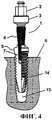
Фиг.5-8 иллюстрируют последовательность съема зубного имплантата (5) с использованием второго варианта осуществления устройства (1) съема имплантата, согласно данному изобретению. В данном случае устройство (1) съема имплантата специально предназначено для съема имплантата (5) с внутренним соединением, то есть оснащенного каналом (7), который содержит анти-вращательную область (15) и цилиндрическую область (16) в дополнение к вышеупомянутой области (12) с резьбой. В данном случае нарезная рабочая часть (4) устройства (1) съема имплантата имеет небольшую длину, так как ее достаточно для того, чтобы ввинтить нарезную рабочую часть (4) в анти-вращательную область (15) и цилиндрическую область (16), чтобы устройство (1) съема имплантата правильно удалило имплантат (5).5-8 illustrate a dental implant removal sequence (5) using a second embodiment of an implant removal device (1) according to the present invention. In this case, the implant removal device (1) is specifically designed to remove the implant (5) with an internal connection, i.e. equipped with a channel (7) that contains an anti-rotational region (15) and a cylindrical region (16) in addition to the aforementioned region ( 12) with thread. In this case, the threaded working part (4) of the implant removal device (1) has a small length, since it is sufficient to screw the threaded working part (4) into the anti-rotational region (15) and the cylindrical region (16) so that the implant removal device (1) correctly removed the implant (5).
На фиг.9 представлен другой вариант осуществления устройства (1) съема имплантата, согласно данному изобретению. В соответствии с данным вариантом осуществления, нарезная рабочая часть (4) содержит первый нарезной участок (4а) уменьшающегося диаметра, цилиндрический нарезной участок (4b), диаметр которого больше внутреннего диаметра канала (7) имплантата (5) (причем указанный канал (7) имеет резьбу в настоящем варианте осуществления), и второй нарезной участок (4с) уменьшающегося диаметра. Фиг.10, 11, 12 иллюстрируют последовательность введения устройства (1) съема имплантата, представленного на фиг.9, в зубной имплантат (5). Второй нарезной участок (4с) уменьшающегося диаметра помогает начать введение и ввинчивание устройства (1) съема имплантата в канал (7) имплантата (5), как показано на фиг.10. В то время как устройство (1) съема имплантата ввинчивается внутрь имплантата (5), цилиндрический нарезной участок (4b) начинает нарезать резьбу, как показано на фиг.11. Поскольку диаметр цилиндрического нарезного участка (4b) больше внутреннего диаметра канала (7), цилиндрический нарезной участок (4b) постепенно разрушает имплантат (5) изнутри, прокладывая новую резьбу и ввинчиваясь в данную новую резьбу. Цилиндрический нарезной участок (4b), таким образом, обеспечивает аксиальное направление устройства (1) съема имплантата вдоль имплантата (5). Наконец, если устройство (1) съема имплантата далее ввинчивается внутрь имплантата (5), как показано на фиг.12, первый нарезной участок (4а) уменьшающегося диаметра начинает нарезать резьбу в канале (7) имплантата (5), прикладывая горизонтальное тяговое усилие к внутренним стенкам указанного канала (7). При достаточно большом тяговом усилии, трение и ввинчивание между первым нарезным участком (4а) уменьшающегося диаметра и стенками канала (7) возрастают до тех пор, пока устройство (1) съема имплантата более не может вращаться внутри канала (7) и крутящий момент передается имплантату (5), в конце концов, заставляя соединение между имплантатом (5) и костной тканью (6) разрушиться (если оно не было еще разрушено) и имплантат (5) вывинтиться из кости (6). В настоящем варианте осуществления крутящий момент поломки прикладывается участком нарезной рабочей части (4), имеющим больший диаметр, то есть первым нарезным участком (4а) уменьшающегося диаметра.Fig. 9 shows another embodiment of an implant removal device (1) according to the present invention. According to this embodiment, the threaded working portion (4) comprises a first threaded portion (4a) of decreasing diameter, a cylindrical threaded portion (4b), the diameter of which is larger than the inner diameter of the implant channel (7) (5) (wherein said channel (7) has a thread in the present embodiment), and a second threaded portion (4c) of decreasing diameter. 10, 11, 12 illustrate the sequence of insertion of the implant removal device (1) of FIG. 9 into a dental implant (5). The second threaded section (4c) of decreasing diameter helps to start the introduction and screwing of the implant removal device (1) into the implant channel (7) (5), as shown in FIG. 10. While the implant removal device (1) is screwed into the implant (5), the cylindrical threaded portion (4b) begins to thread, as shown in FIG. 11. Since the diameter of the cylindrical threaded section (4b) is larger than the internal diameter of the channel (7), the cylindrical threaded section (4b) gradually destroys the implant (5) from the inside, laying a new thread and screwing into this new thread. The cylindrical threaded section (4b) thus provides the axial direction of the implant removal device (1) along the implant (5). Finally, if the implant removal device (1) is further screwed into the implant (5), as shown in FIG. 12, the first threaded portion (4a) of decreasing diameter begins to thread in the channel (7) of the implant (5), applying a horizontal pulling force to the inner walls of the specified channel (7). With a sufficiently large pulling force, friction and screwing between the first threaded section (4a) of decreasing diameter and the walls of the channel (7) increase until the device (1) for removing the implant can no longer rotate inside the channel (7) and the torque is transmitted to the implant (5) finally causing the joint between the implant (5) and the bone tissue (6) to break down (if it has not already been destroyed) and the implant (5) to be screwed out of the bone (6). In the present embodiment, a breakdown torque is applied by a portion of a threaded working portion (4) having a larger diameter, that is, a first threaded portion (4a) of decreasing diameter.
В настоящем варианте осуществления крутящий момент извлечения должен прикладываться участком, имеющим большой диаметр (вышеупомянутым первым нарезным участком (4а) уменьшающегося диаметра). Следовательно, так как это больший (и поэтому более прочный) участок, который отвечает за приложение крутящего момента извлечения, и так как контактная поверхность между устройством (1) съема имплантата и имплантатом (5) больше, то риск поломки устройства (1) съема имплантата во время использования мал и одновременно к имплантату (5) может быть приложен крутящий момент большей величины, значит, легче разрушить соединение между имплантатом (5) и костью (6).In the present embodiment, the extraction torque should be applied by a portion having a large diameter (the aforementioned first threaded portion (4a) of decreasing diameter). Therefore, since this is a larger (and therefore more durable) area, which is responsible for applying the extraction torque, and since the contact surface between the implant removal device (1) and the implant (5) is greater, the risk of failure of the implant removal device (1) is broken during use it is small and at the same time a larger torque can be applied to the implant (5), which means that it is easier to break the connection between the implant (5) and the bone (6).
Предпочтительно, первый нарезной участок (4а) уменьшающегося диаметра и/или второй нарезной участок (4с) уменьшающегося диаметра имеют форму конуса, поскольку такой вариант осуществления является наиболее простым и в равной степени эффективным.Preferably, the first threaded portion (4a) of decreasing diameter and / or the second threaded portion (4c) of decreasing diameter are conical in shape since this embodiment is the simplest and equally effective.
Claims (5)
- головную часть (2), к которой надлежит прикрепить систему, способную обеспечить крутящий момент устройству (1) съема имплантата;
- нарезную рабочую часть (4), которую надлежит ввинтить в канал (7) имплантата (5);
при этом нарезная рабочая часть (4) содержит первый нарезной участок (4а) уменьшающегося диаметра, цилиндрический нарезной участок (4b), диаметр которого больше внутреннего диаметра канала (7) имплантата (5), и второй нарезной участок (4с) уменьшающегося диаметра.1. The device (1) removal of the implant, allowing to remove the implant (5) attached to the bone (6) of the patient, while the implant (5) contains a channel (7), characterized in that it includes:
- the head part (2) to which the system is to be attached, capable of providing torque to the implant removal device (1);
- threaded working part (4), which must be screwed into the channel (7) of the implant (5);
wherein the threaded working part (4) contains a first threaded portion (4a) of decreasing diameter, a cylindrical threaded portion (4b), the diameter of which is larger than the inner diameter of the channel (7) of the implant (5), and a second threaded portion (4c) of decreasing diameter.
Applications Claiming Priority (5)
| Application Number | Priority Date | Filing Date | Title |
|---|---|---|---|
| ESP200801858 | 2008-06-20 | ||
| ES200801858A ES2344240B1 (en) | 2008-06-20 | 2008-06-20 | TOOL TO ALLOW THE EXTRACTION OF AN IMPLANT. |
| US12/198,213 US20090317771A1 (en) | 2008-06-20 | 2008-08-26 | Implant removal tool |
| US12/198,213 | 2008-08-26 | ||
| PCT/ES2009/000335 WO2009153372A2 (en) | 2008-06-20 | 2009-06-18 | Implant extraction tool |
Publications (2)
| Publication Number | Publication Date |
|---|---|
| RU2011101940A RU2011101940A (en) | 2012-07-27 |
| RU2476183C2 true RU2476183C2 (en) | 2013-02-27 |
Family
ID=41434495
Family Applications (1)
| Application Number | Title | Priority Date | Filing Date |
|---|---|---|---|
| RU2011101940/14A RU2476183C2 (en) | 2008-06-20 | 2009-06-18 | Device for implant removal |
Country Status (18)
| Country | Link |
|---|---|
| US (1) | US9241776B2 (en) |
| EP (1) | EP2283792B1 (en) |
| JP (1) | JP5442007B2 (en) |
| KR (1) | KR101620329B1 (en) |
| CN (1) | CN102076279A (en) |
| AR (1) | AR074154A1 (en) |
| BR (1) | BRPI0909924B8 (en) |
| CA (1) | CA2728147C (en) |
| CL (1) | CL2010001480A1 (en) |
| CO (1) | CO6321206A2 (en) |
| ES (2) | ES2344240B1 (en) |
| MX (1) | MX2010013268A (en) |
| PE (1) | PE20110443A1 (en) |
| PL (1) | PL2283792T3 (en) |
| PT (1) | PT2283792E (en) |
| RU (1) | RU2476183C2 (en) |
| TW (1) | TWI536972B (en) |
| WO (1) | WO2009153372A2 (en) |
Families Citing this family (13)
| Publication number | Priority date | Publication date | Assignee | Title |
|---|---|---|---|---|
| ES2388549B1 (en) * | 2010-03-10 | 2013-09-13 | Biotechnology Inst I Mas D Sl | METHOD OF EXTRACTION OF IMPLANTS AND DRILL OF TREFINA TO FACILITATE EXTRACTION. |
| ES2347634B1 (en) * | 2010-03-10 | 2011-09-08 | Biotechnology Institute, I Mas D, S.L. | EXTENSIVE TOOL FOR TORQUE APPLICATION ON A DENTAL IMPLANT. |
| ES2390766B1 (en) | 2010-09-30 | 2014-01-17 | Biotechnology Institute, I Mas D, S.L. | OSEA CRESTA EXPANSION METHOD AND AN EXPANSOR IMPLANT TO BE USED IN THIS METHOD |
| JP2015536176A (en) * | 2012-11-15 | 2015-12-21 | 何 志忠HO, Chih−Chung | Dental implant having first female screw and second female screw |
| CN104055588A (en) * | 2013-07-03 | 2014-09-24 | 广州中国科学院先进技术研究所 | Implanting tool for dental implant |
| KR101570615B1 (en) | 2014-09-04 | 2015-11-19 | 허덕수 | Fixture remover for implant |
| JP6411234B2 (en) * | 2015-01-29 | 2018-10-24 | 京セラ株式会社 | Dental implant removal device |
| JP2016154856A (en) * | 2015-02-25 | 2016-09-01 | 株式会社DentalBank | Dental jig, artificial bone for filling removal hole, trephine bar, and manufacturing method of dental jig |
| CN105662605A (en) * | 2016-03-16 | 2016-06-15 | 吴大怡 | Residual root noninvasive dislocation device |
| US10966842B2 (en) | 2017-07-13 | 2021-04-06 | The University Of Hong Kong | Surgical extraction device for bone implant tips |
| US20210052356A1 (en) * | 2019-08-19 | 2021-02-25 | Dentsply Sirona Inc. | Dental device for removing a partially or fully osseointegrated dental implant |
| CN112190351B (en) * | 2020-09-17 | 2021-06-04 | 四川大学 | Fixing device for tooth extraction |
| TWI824408B (en) * | 2022-02-09 | 2023-12-01 | 鈴木計芳 | tooth extraction kit |
Citations (5)
| Publication number | Priority date | Publication date | Assignee | Title |
|---|---|---|---|---|
| US3702028A (en) * | 1972-11-07 | 1972-11-07 | Alfred E Edelman | Dental implant extracting tool |
| ES289364U (en) * | 1985-10-02 | 1986-10-01 | Toboso Ramon Jesus | Device extractor of dental parts by internal traction. (Machine-translation by Google Translate, not legally binding) |
| US4834081A (en) * | 1988-01-11 | 1989-05-30 | Boehringer Mannheim Corporation | Tool for removing modular joint prosthesis |
| US6019602A (en) * | 1998-10-05 | 2000-02-01 | Fletcher; Tarrie | Tooth root tip extractor |
| RU90981U1 (en) * | 2009-08-04 | 2010-01-27 | Марсель Закиевич Миргазизов | DEVICE FOR ATRAUMATIC REMOVAL OF TEETH ROOTS |
Family Cites Families (18)
| Publication number | Priority date | Publication date | Assignee | Title |
|---|---|---|---|---|
| US413968A (en) * | 1889-10-29 | Island | ||
| GB496988A (en) * | 1937-04-24 | 1938-12-09 | Peter Van Beeck | Instrument for extracting roots of teeth |
| ES2103196B1 (en) * | 1995-08-03 | 1998-04-01 | Cardona Labarga Carlos Fernand | EXTRACTION SYSTEM OF DEFINITIVELY CEMENTED PROSTHESES IN IMPLANTS. |
| WO2000032125A1 (en) * | 1998-11-26 | 2000-06-08 | Synthes Ag Chur | Screw |
| US6733506B1 (en) * | 2000-11-16 | 2004-05-11 | Ethicon, Inc. | Apparatus and method for attaching soft tissue to bone |
| GB0108551D0 (en) * | 2001-04-05 | 2001-05-23 | Osseobiotek Ltd | Implant |
| JP2002355768A (en) * | 2001-05-31 | 2002-12-10 | Kaneko Seisakusho:Kk | Screw removing tool attached to electric rotation tool |
| US6923648B1 (en) * | 2003-04-22 | 2005-08-02 | Jeff Rassoli | Dental implant fastener system |
| JP2005270334A (en) * | 2004-03-24 | 2005-10-06 | Shoichi Saito | Dental implant |
| US20050250073A1 (en) * | 2004-05-04 | 2005-11-10 | Tresser Yuval A | Reversible screw blockage, with application to the attachment of prosthetic abutments to dental implants |
| SE0401808D0 (en) * | 2004-07-08 | 2004-07-08 | Astra Tech Ab | Dental implanting system |
| ES2363202T3 (en) * | 2005-02-08 | 2011-07-26 | Biotechnology Institute, I Mas D, S.L. | NARROW DENTAL IMPLANT AND ASSOCIATED PARTS. |
| KR100594753B1 (en) | 2005-02-15 | 2006-06-30 | 김정찬 | Mount device for dental implant |
| EP1728486A1 (en) * | 2005-06-03 | 2006-12-06 | Straumann Holding AG | Coupling for a multi-part dental implant system |
| US20070093791A1 (en) * | 2005-09-19 | 2007-04-26 | Inion Ltd. | Device for removal of fastening means from human tissue |
| JP2008061672A (en) * | 2006-09-05 | 2008-03-21 | Tokyo Ootomakku Kk | Rotary vibration imparting apparatus for implant |
| KR100758360B1 (en) | 2006-11-06 | 2007-09-14 | 오스템임플란트 주식회사 | Mount device |
| KR100788240B1 (en) * | 2006-12-04 | 2007-12-27 | 장경삼 | The dental implant unit for extracting which becomes to the left screw |
-
2008
- 2008-06-20 ES ES200801858A patent/ES2344240B1/en not_active Expired - Fee Related
-
2009
- 2009-06-17 TW TW098120233A patent/TWI536972B/en active
- 2009-06-18 EP EP09765945.2A patent/EP2283792B1/en active Active
- 2009-06-18 CN CN2009801230633A patent/CN102076279A/en active Pending
- 2009-06-18 JP JP2011514071A patent/JP5442007B2/en active Active
- 2009-06-18 BR BRPI0909924A patent/BRPI0909924B8/en active IP Right Grant
- 2009-06-18 MX MX2010013268A patent/MX2010013268A/en active IP Right Grant
- 2009-06-18 ES ES09765945.2T patent/ES2576688T3/en active Active
- 2009-06-18 PT PT09765945T patent/PT2283792E/en unknown
- 2009-06-18 US US13/000,263 patent/US9241776B2/en active Active
- 2009-06-18 RU RU2011101940/14A patent/RU2476183C2/en active
- 2009-06-18 KR KR1020117001358A patent/KR101620329B1/en active IP Right Grant
- 2009-06-18 PE PE2010001167A patent/PE20110443A1/en not_active Application Discontinuation
- 2009-06-18 PL PL09765945.2T patent/PL2283792T3/en unknown
- 2009-06-18 WO PCT/ES2009/000335 patent/WO2009153372A2/en active Application Filing
- 2009-06-18 CA CA2728147A patent/CA2728147C/en active Active
- 2009-06-19 AR ARP090102258A patent/AR074154A1/en not_active Application Discontinuation
-
2010
- 2010-12-17 CL CL2010001480A patent/CL2010001480A1/en unknown
- 2010-12-20 CO CO10159635A patent/CO6321206A2/en active IP Right Grant
Patent Citations (5)
| Publication number | Priority date | Publication date | Assignee | Title |
|---|---|---|---|---|
| US3702028A (en) * | 1972-11-07 | 1972-11-07 | Alfred E Edelman | Dental implant extracting tool |
| ES289364U (en) * | 1985-10-02 | 1986-10-01 | Toboso Ramon Jesus | Device extractor of dental parts by internal traction. (Machine-translation by Google Translate, not legally binding) |
| US4834081A (en) * | 1988-01-11 | 1989-05-30 | Boehringer Mannheim Corporation | Tool for removing modular joint prosthesis |
| US6019602A (en) * | 1998-10-05 | 2000-02-01 | Fletcher; Tarrie | Tooth root tip extractor |
| RU90981U1 (en) * | 2009-08-04 | 2010-01-27 | Марсель Закиевич Миргазизов | DEVICE FOR ATRAUMATIC REMOVAL OF TEETH ROOTS |
Also Published As
| Publication number | Publication date |
|---|---|
| BRPI0909924B1 (en) | 2019-11-05 |
| TW201006445A (en) | 2010-02-16 |
| TWI536972B (en) | 2016-06-11 |
| EP2283792A4 (en) | 2013-12-11 |
| WO2009153372A2 (en) | 2009-12-23 |
| PL2283792T3 (en) | 2016-09-30 |
| PE20110443A1 (en) | 2011-07-15 |
| EP2283792B1 (en) | 2016-04-13 |
| ES2576688T3 (en) | 2016-07-08 |
| EP2283792A2 (en) | 2011-02-16 |
| CL2010001480A1 (en) | 2011-05-27 |
| CN102076279A (en) | 2011-05-25 |
| KR20110033215A (en) | 2011-03-30 |
| JP5442007B2 (en) | 2014-03-12 |
| BRPI0909924A2 (en) | 2015-10-20 |
| US20110172673A1 (en) | 2011-07-14 |
| WO2009153372A3 (en) | 2010-02-18 |
| ES2344240B1 (en) | 2011-06-13 |
| ES2344240A1 (en) | 2010-08-20 |
| BRPI0909924B8 (en) | 2021-06-22 |
| CO6321206A2 (en) | 2011-09-20 |
| JP2011524759A (en) | 2011-09-08 |
| MX2010013268A (en) | 2011-02-25 |
| RU2011101940A (en) | 2012-07-27 |
| PT2283792E (en) | 2016-06-08 |
| US9241776B2 (en) | 2016-01-26 |
| CA2728147C (en) | 2016-10-18 |
| KR101620329B1 (en) | 2016-05-12 |
| CA2728147A1 (en) | 2009-12-23 |
| AR074154A1 (en) | 2010-12-29 |
Similar Documents
| Publication | Publication Date | Title |
|---|---|---|
| RU2476183C2 (en) | Device for implant removal | |
| KR100594753B1 (en) | Mount device for dental implant | |
| KR101246265B1 (en) | Implant fixture remover | |
| US20100055644A1 (en) | Dental implant for implanting an artificial tooth on the anterior portion of the mandible of a patient | |
| US20080090206A1 (en) | Extractor for broken tooth root | |
| US20090220914A1 (en) | Dental implant and a method of implantation thereof | |
| US8162663B2 (en) | Dental implant | |
| US20090317771A1 (en) | Implant removal tool | |
| KR100788240B1 (en) | The dental implant unit for extracting which becomes to the left screw | |
| WO2007058125A1 (en) | Dental implant | |
| RU2694886C2 (en) | Trephine drill to enable extraction | |
| KR101083058B1 (en) | Broken screw removing guider of Abutment for a dental implant | |
| KR101834175B1 (en) | Implant-expander for expanding the jawbone crest | |
| KR20070047991A (en) | The abutment and the removal apparatus which applies the abutment | |
| KR20150138615A (en) | The fixture separation method of dental implant and thereof device | |
| EP1576935A1 (en) | Endosseous dental implant | |
| RU109656U1 (en) | DENTAL IMPLANT | |
| KR20110007721U (en) | Eliminator for implant | |
| JP2001299777A (en) | Jig for dental implant investment | |
| WO2014064851A1 (en) | Abutment, fixture, connector, and set for dental implant | |
| KR20200078151A (en) | Pre-mount device for removing fixtures on D4 bones using lower cavity structure | |
| WO2011071419A2 (en) | Dental implant |