RU2474446C1 - Expandable face mask with supporting net - Google Patents
Expandable face mask with supporting net Download PDFInfo
- Publication number
- RU2474446C1 RU2474446C1 RU2011124947/12A RU2011124947A RU2474446C1 RU 2474446 C1 RU2474446 C1 RU 2474446C1 RU 2011124947/12 A RU2011124947/12 A RU 2011124947/12A RU 2011124947 A RU2011124947 A RU 2011124947A RU 2474446 C1 RU2474446 C1 RU 2474446C1
- Authority
- RU
- Russia
- Prior art keywords
- porous layer
- mesh
- mask
- face mask
- layer
- Prior art date
Links
Images
Classifications
-
- A—HUMAN NECESSITIES
- A62—LIFE-SAVING; FIRE-FIGHTING
- A62B—DEVICES, APPARATUS OR METHODS FOR LIFE-SAVING
- A62B18/00—Breathing masks or helmets, e.g. affording protection against chemical agents or for use at high altitudes or incorporating a pump or compressor for reducing the inhalation effort
- A62B18/02—Masks
- A62B18/025—Halfmasks
-
- A—HUMAN NECESSITIES
- A41—WEARING APPAREL
- A41D—OUTERWEAR; PROTECTIVE GARMENTS; ACCESSORIES
- A41D13/00—Professional, industrial or sporting protective garments, e.g. surgeons' gowns or garments protecting against blows or punches
- A41D13/05—Professional, industrial or sporting protective garments, e.g. surgeons' gowns or garments protecting against blows or punches protecting only a particular body part
- A41D13/11—Protective face masks, e.g. for surgical use, or for use in foul atmospheres
- A41D13/1107—Protective face masks, e.g. for surgical use, or for use in foul atmospheres characterised by their shape
- A41D13/1115—Protective face masks, e.g. for surgical use, or for use in foul atmospheres characterised by their shape with a horizontal pleated pocket
-
- A—HUMAN NECESSITIES
- A62—LIFE-SAVING; FIRE-FIGHTING
- A62B—DEVICES, APPARATUS OR METHODS FOR LIFE-SAVING
- A62B23/00—Filters for breathing-protection purposes
- A62B23/02—Filters for breathing-protection purposes for respirators
- A62B23/025—Filters for breathing-protection purposes for respirators the filter having substantially the shape of a mask
-
- B—PERFORMING OPERATIONS; TRANSPORTING
- B32—LAYERED PRODUCTS
- B32B—LAYERED PRODUCTS, i.e. PRODUCTS BUILT-UP OF STRATA OF FLAT OR NON-FLAT, e.g. CELLULAR OR HONEYCOMB, FORM
- B32B3/00—Layered products comprising a layer with external or internal discontinuities or unevennesses, or a layer of non-planar form; Layered products having particular features of form
- B32B3/10—Layered products comprising a layer with external or internal discontinuities or unevennesses, or a layer of non-planar form; Layered products having particular features of form characterised by a discontinuous layer, i.e. formed of separate pieces of material
-
- B—PERFORMING OPERATIONS; TRANSPORTING
- B32—LAYERED PRODUCTS
- B32B—LAYERED PRODUCTS, i.e. PRODUCTS BUILT-UP OF STRATA OF FLAT OR NON-FLAT, e.g. CELLULAR OR HONEYCOMB, FORM
- B32B3/00—Layered products comprising a layer with external or internal discontinuities or unevennesses, or a layer of non-planar form; Layered products having particular features of form
- B32B3/26—Layered products comprising a layer with external or internal discontinuities or unevennesses, or a layer of non-planar form; Layered products having particular features of form characterised by a particular shape of the outline of the cross-section of a continuous layer; characterised by a layer with cavities or internal voids ; characterised by an apertured layer
- B32B3/30—Layered products comprising a layer with external or internal discontinuities or unevennesses, or a layer of non-planar form; Layered products having particular features of form characterised by a particular shape of the outline of the cross-section of a continuous layer; characterised by a layer with cavities or internal voids ; characterised by an apertured layer characterised by a layer formed with recesses or projections, e.g. hollows, grooves, protuberances, ribs
-
- B—PERFORMING OPERATIONS; TRANSPORTING
- B32—LAYERED PRODUCTS
- B32B—LAYERED PRODUCTS, i.e. PRODUCTS BUILT-UP OF STRATA OF FLAT OR NON-FLAT, e.g. CELLULAR OR HONEYCOMB, FORM
- B32B5/00—Layered products characterised by the non- homogeneity or physical structure, i.e. comprising a fibrous, filamentary, particulate or foam layer; Layered products characterised by having a layer differing constitutionally or physically in different parts
- B32B5/22—Layered products characterised by the non- homogeneity or physical structure, i.e. comprising a fibrous, filamentary, particulate or foam layer; Layered products characterised by having a layer differing constitutionally or physically in different parts characterised by the presence of two or more layers which are next to each other and are fibrous, filamentary, formed of particles or foamed
-
- B—PERFORMING OPERATIONS; TRANSPORTING
- B32—LAYERED PRODUCTS
- B32B—LAYERED PRODUCTS, i.e. PRODUCTS BUILT-UP OF STRATA OF FLAT OR NON-FLAT, e.g. CELLULAR OR HONEYCOMB, FORM
- B32B1/00—Layered products having a general shape other than plane
-
- B—PERFORMING OPERATIONS; TRANSPORTING
- B32—LAYERED PRODUCTS
- B32B—LAYERED PRODUCTS, i.e. PRODUCTS BUILT-UP OF STRATA OF FLAT OR NON-FLAT, e.g. CELLULAR OR HONEYCOMB, FORM
- B32B2250/00—Layers arrangement
- B32B2250/20—All layers being fibrous or filamentary
-
- B—PERFORMING OPERATIONS; TRANSPORTING
- B32—LAYERED PRODUCTS
- B32B—LAYERED PRODUCTS, i.e. PRODUCTS BUILT-UP OF STRATA OF FLAT OR NON-FLAT, e.g. CELLULAR OR HONEYCOMB, FORM
- B32B27/00—Layered products comprising a layer of synthetic resin
- B32B27/12—Layered products comprising a layer of synthetic resin next to a fibrous or filamentary layer
-
- B—PERFORMING OPERATIONS; TRANSPORTING
- B32—LAYERED PRODUCTS
- B32B—LAYERED PRODUCTS, i.e. PRODUCTS BUILT-UP OF STRATA OF FLAT OR NON-FLAT, e.g. CELLULAR OR HONEYCOMB, FORM
- B32B5/00—Layered products characterised by the non- homogeneity or physical structure, i.e. comprising a fibrous, filamentary, particulate or foam layer; Layered products characterised by having a layer differing constitutionally or physically in different parts
- B32B5/02—Layered products characterised by the non- homogeneity or physical structure, i.e. comprising a fibrous, filamentary, particulate or foam layer; Layered products characterised by having a layer differing constitutionally or physically in different parts characterised by structural features of a fibrous or filamentary layer
- B32B5/022—Non-woven fabric
-
- B—PERFORMING OPERATIONS; TRANSPORTING
- B32—LAYERED PRODUCTS
- B32B—LAYERED PRODUCTS, i.e. PRODUCTS BUILT-UP OF STRATA OF FLAT OR NON-FLAT, e.g. CELLULAR OR HONEYCOMB, FORM
- B32B5/00—Layered products characterised by the non- homogeneity or physical structure, i.e. comprising a fibrous, filamentary, particulate or foam layer; Layered products characterised by having a layer differing constitutionally or physically in different parts
- B32B5/02—Layered products characterised by the non- homogeneity or physical structure, i.e. comprising a fibrous, filamentary, particulate or foam layer; Layered products characterised by having a layer differing constitutionally or physically in different parts characterised by structural features of a fibrous or filamentary layer
- B32B5/028—Net structure, e.g. spaced apart filaments bonded at the crossing points
-
- Y—GENERAL TAGGING OF NEW TECHNOLOGICAL DEVELOPMENTS; GENERAL TAGGING OF CROSS-SECTIONAL TECHNOLOGIES SPANNING OVER SEVERAL SECTIONS OF THE IPC; TECHNICAL SUBJECTS COVERED BY FORMER USPC CROSS-REFERENCE ART COLLECTIONS [XRACs] AND DIGESTS
- Y10—TECHNICAL SUBJECTS COVERED BY FORMER USPC
- Y10T—TECHNICAL SUBJECTS COVERED BY FORMER US CLASSIFICATION
- Y10T156/00—Adhesive bonding and miscellaneous chemical manufacture
- Y10T156/10—Methods of surface bonding and/or assembly therefor
- Y10T156/1002—Methods of surface bonding and/or assembly therefor with permanent bending or reshaping or surface deformation of self sustaining lamina
- Y10T156/1051—Methods of surface bonding and/or assembly therefor with permanent bending or reshaping or surface deformation of self sustaining lamina by folding
-
- Y—GENERAL TAGGING OF NEW TECHNOLOGICAL DEVELOPMENTS; GENERAL TAGGING OF CROSS-SECTIONAL TECHNOLOGIES SPANNING OVER SEVERAL SECTIONS OF THE IPC; TECHNICAL SUBJECTS COVERED BY FORMER USPC CROSS-REFERENCE ART COLLECTIONS [XRACs] AND DIGESTS
- Y10—TECHNICAL SUBJECTS COVERED BY FORMER USPC
- Y10T—TECHNICAL SUBJECTS COVERED BY FORMER US CLASSIFICATION
- Y10T428/00—Stock material or miscellaneous articles
- Y10T428/24—Structurally defined web or sheet [e.g., overall dimension, etc.]
- Y10T428/24479—Structurally defined web or sheet [e.g., overall dimension, etc.] including variation in thickness
- Y10T428/2457—Parallel ribs and/or grooves
-
- Y—GENERAL TAGGING OF NEW TECHNOLOGICAL DEVELOPMENTS; GENERAL TAGGING OF CROSS-SECTIONAL TECHNOLOGIES SPANNING OVER SEVERAL SECTIONS OF THE IPC; TECHNICAL SUBJECTS COVERED BY FORMER USPC CROSS-REFERENCE ART COLLECTIONS [XRACs] AND DIGESTS
- Y10—TECHNICAL SUBJECTS COVERED BY FORMER USPC
- Y10T—TECHNICAL SUBJECTS COVERED BY FORMER US CLASSIFICATION
- Y10T428/00—Stock material or miscellaneous articles
- Y10T428/24—Structurally defined web or sheet [e.g., overall dimension, etc.]
- Y10T428/24942—Structurally defined web or sheet [e.g., overall dimension, etc.] including components having same physical characteristic in differing degree
- Y10T428/2495—Thickness [relative or absolute]
-
- Y—GENERAL TAGGING OF NEW TECHNOLOGICAL DEVELOPMENTS; GENERAL TAGGING OF CROSS-SECTIONAL TECHNOLOGIES SPANNING OVER SEVERAL SECTIONS OF THE IPC; TECHNICAL SUBJECTS COVERED BY FORMER USPC CROSS-REFERENCE ART COLLECTIONS [XRACs] AND DIGESTS
- Y10—TECHNICAL SUBJECTS COVERED BY FORMER USPC
- Y10T—TECHNICAL SUBJECTS COVERED BY FORMER US CLASSIFICATION
- Y10T442/00—Fabric [woven, knitted, or nonwoven textile or cloth, etc.]
- Y10T442/10—Scrim [e.g., open net or mesh, gauze, loose or open weave or knit, etc.]
- Y10T442/102—Woven scrim
- Y10T442/159—Including a nonwoven fabric which is not a scrim
-
- Y—GENERAL TAGGING OF NEW TECHNOLOGICAL DEVELOPMENTS; GENERAL TAGGING OF CROSS-SECTIONAL TECHNOLOGIES SPANNING OVER SEVERAL SECTIONS OF THE IPC; TECHNICAL SUBJECTS COVERED BY FORMER USPC CROSS-REFERENCE ART COLLECTIONS [XRACs] AND DIGESTS
- Y10—TECHNICAL SUBJECTS COVERED BY FORMER USPC
- Y10T—TECHNICAL SUBJECTS COVERED BY FORMER US CLASSIFICATION
- Y10T442/00—Fabric [woven, knitted, or nonwoven textile or cloth, etc.]
- Y10T442/10—Scrim [e.g., open net or mesh, gauze, loose or open weave or knit, etc.]
- Y10T442/184—Nonwoven scrim
- Y10T442/197—Including a nonwoven fabric which is not a scrim
Abstract
Description
Уровень техникиState of the art
Лицевые маски применяются для различных целей. Они надеваются поверх носа и рта пользователя, например, для защиты органов дыхания от взвешенных в воздухе частиц и/или неприятно пахнущих или ядовитых газов, для уменьшения попадания в окружающее пространство компонентов, содержащихся в воздухе, выдыхаемом пользователем, или для обеих данных целей. Такие маски предлагаются в виде двух основных типов: формованная маска готовой чашеобразной формы и плоская в сложенном виде и раскрываемая до чашеобразной формы.Face masks are used for various purposes. They are worn over the user's nose and mouth, for example, to protect the respiratory system from particles suspended in the air and / or unpleasantly smelling or toxic gases, to reduce the ingress of components contained in the air exhaled by the user, or both. Such masks are offered in the form of two main types: a preformed cup-shaped shaped mask and a flat one when folded and expanded to a cup-shaped shape.
Сущность изобретенияSUMMARY OF THE INVENTION
В настоящем изобретении предлагается ряд воплощений лицевой маски (далее именуемой «маска»), поставляемой в сложенном до практически плоского состояния виде и раскладывающейся с образованием воздушной камеры чашеобразной формы, которая может быть надета поверх носа и рта пользователя. Маска содержит по меньшей мере один пористый слой, который содержит по меньшей мере одну складку и который может быть растянут от меньшей площади до большей площади путем по меньшей мере частичного разворачивания по меньшей мере одной складки. Пористый слой содержит первую основную поверхность, обращенную от пользователя, когда маска раскрыта до чашеобразной формы, и вторую основную поверхность, обращенную к пользователю, когда маска раскрыта таким же образом. Маска дополнительно содержит армирующую сетку, ламинированную с большей частью первой основной поверхности пористого слоя.The present invention provides a series of embodiments of a face mask (hereinafter referred to as “the mask”), which is supplied folded to a substantially flat state and expanded to form a cup-shaped air chamber that can be worn over the user's nose and mouth. The mask contains at least one porous layer that contains at least one crease and which can be stretched from a smaller area to a larger area by at least partially unrolling at least one crease. The porous layer comprises a first main surface facing away from the user when the mask is opened to a cup shape, and a second main surface facing the user when the mask is opened in the same way. The mask further comprises a reinforcing mesh laminated with most of the first major surface of the porous layer.
Наличие армирующей сетки позволяет использовать относительно легкие по весу и деликатные, но обладающие высокой пористостью материалы в пористом слое, например, позволяет успешно проводить обработку таких материалов в процессе сборки маски и использовать преимущества их легкости и деликатности, например получать пористый слой, обеспечивающий малое падение давления. Сетка может также придавать повышенную прочность, долговечность и устойчивость к истиранию пористому слою маски, несмотря на использование в нем легковесных и деликатных материалов.The presence of a reinforcing mesh allows the use of relatively light in weight and delicate, but highly porous materials in the porous layer, for example, it allows to successfully process such materials in the process of mask assembly and take advantage of their lightness and delicacy, for example, to obtain a porous layer that provides a low pressure drop . The mesh can also impart increased strength, durability and abrasion resistance to the porous layer of the mask, despite the use of lightweight and delicate materials.
В соответствии с настоящим изобретением, сетка может быть сложена по складкам вместе с пористым слоем (так что вся маска может поставляться потребителю в сложенном до плоского состояния виде). Сетка может способствовать лучшему сохранению маской своей формы в раскрытом состоянии, и в то же время сетка может быть обратно сложена вместе с пористым слоем, так что и вся маска может быть обратно сложена до плоского состояния. В частности, сетка позволяет производить многократное раскрытие и обратное сложение маски потребителем, при наличии у него такой необходимости.In accordance with the present invention, the mesh can be folded along the folds together with the porous layer (so that the entire mask can be delivered to the consumer in a folded flat form). The mesh can help the mask to better maintain its shape in the open state, and at the same time, the mesh can be folded back together with the porous layer, so that the entire mask can be folded back to a flat state. In particular, the grid allows multiple disclosure and reverse folding of the mask by the consumer, if he has such a need.
Поэтому в одном из типов воплощений настоящего изобретения предлагается плоская в сложенном виде, складчатая лицевая маска, которая, будучи раскрыта, может принимать чашеобразную форму, обеспечивающую посадку на лицо человека поверх носа и рта, содержащая: пористый слой, содержащий по меньшей мере первую основную поверхность, обращенную в целом наружу, когда маска раскрыта до чашеобразной формы, и содержащий армирующую сетку, ламинированную по меньшей мере с частью его первой основной поверхности, причем часть пористого слоя, содержащая армирующую сетку, ламинированную с его первой основной поверхностью, содержит по меньшей мере одну складку и поэтому может быть раскрыта из плоского сложенного состояния до чашеобразного состояния путем по меньшей мере частичного разворачивания по меньшей мере одной складки и может быть обратно сложена из раскрытого, чашеобразного состояния до плоского состояния путем обратного сложения по меньшей мере одной складки.Therefore, in one type of embodiment of the present invention, there is provided a folded flat, folded face mask, which, when opened, can take a cup-shaped shape that allows it to fit on a person’s face over the nose and mouth, comprising: a porous layer containing at least a first major surface facing generally outward when the mask is opened to a cup shape and containing a reinforcing mesh laminated with at least a portion of its first main surface, wherein a portion of the porous layer containing the reinforcing mesh laminated with its first main surface contains at least one fold and therefore can be opened from a flat folded state to a cup-like state by at least partially unfolding at least one fold and can be folded back from an open, cup-shaped state to flat state by the reverse addition of at least one fold.
Во втором типе воплощений настоящего изобретения предлагается способ изготовления плоской в сложенном виде, складчатой лицевой маски, которая, будучи раскрыта, может принимать чашеобразную форму, обеспечивающую посадку на лицо человека поверх носа и рта, содержащий этапы: обеспечения ламината, содержащего нетканое полотно, содержащее находящиеся друг напротив друга первую и вторую основные поверхности, причем к первой основной поверхности ламинирована армирующая сетка; обеспечения по меньшей мере одного пористого слоя, имеющего находящиеся друг напротив друга первую и вторую основные поверхности; прикрепления ламината к упомянутому по меньшей мере одному пористому слою, так что вторая основная поверхность нетканого полотна будет обращена к одной из поверхностей упомянутого по меньшей мере одного пористого слоя, в результате чего будет получена многослойная структура; и формирования по меньшей мере одной складки в полученной многослойной структуре.In the second type of embodiments of the present invention, there is provided a method of manufacturing a folded flat, folded face mask, which, when opened, can take a cup shape, which fits onto a person’s face over the nose and mouth, comprising the steps of: providing a laminate containing a non-woven fabric containing opposite each other, the first and second main surfaces, and a reinforcing mesh is laminated to the first main surface; providing at least one porous layer having opposite one another first and second major surfaces; attaching the laminate to said at least one porous layer, so that the second major surface of the nonwoven fabric will face one of the surfaces of said at least one porous layer, resulting in a multilayer structure; and forming at least one fold in the resulting multilayer structure.
Эти, а также прочие воплощения изобретения будут более понятны из подробного описания, приведенного ниже. Приведенные выше краткие описания воплощений ни в коем случае, однако, не следует рассматривать как ограничения предмета изобретения, который в свою очередь определяется исключительно прилагаемой формулой изобретения, которая может быть скорректирована в процессе рассмотрения заявки.These, as well as other embodiments of the invention will be more apparent from the detailed description below. The above brief descriptions of the embodiments in no case, however, should not be construed as limiting the subject of the invention, which in turn is determined solely by the attached claims, which can be adjusted during the consideration of the application.
Краткое описание чертежейBrief Description of the Drawings
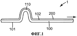
Фиг.1. Поперечное сечение фрагмента одного из воплощений складчатой маски в нераскрытом состоянии.Figure 1. Cross section of a fragment of one of the embodiments of the folded mask in an undisclosed state.
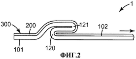
Фиг.2. Поперечное сечение фрагмента второго воплощения складчатой маски в нераскрытом состоянии.Figure 2. Cross section of a fragment of a second embodiment of a folded mask in an undisclosed state.
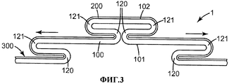
Фиг.3. Поперечное сечение фрагмента еще одного воплощения складчатой маски в нераскрытом состоянии.Figure 3. Cross section of a fragment of another embodiment of a folded mask in an undisclosed state.
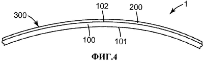
Фиг.4. Поперечное сечение фрагмента еще одного воплощения складчатой маски в нераскрытом состоянии.Figure 4. Cross section of a fragment of another embodiment of a folded mask in an undisclosed state.
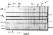
Фиг.5. Вид сверху одного из воплощений складчатой маски в нераскрытом состоянии.Figure 5. Top view of one of the embodiments of the folded mask in an undisclosed state.
Фиг.6. Вид сверху еще одного из воплощений складчатой маски в нераскрытом состоянии.6. Top view of another embodiment of a folded mask in an undisclosed state.
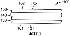
Фиг.7. Схематичное поперечное сечение фрагмента одного из воплощений пористого слоя.7. Schematic cross section of a fragment of one of the embodiments of the porous layer.
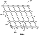
Фиг.8. Аксонометрический вид одного из воплощений армирующей сетки.Fig. 8. Axonometric view of one of the embodiments of the reinforcing mesh.
Аналогичными номерами позиций на разных чертежах обозначены аналогичные элементы. Если не указано иное, все чертежи в настоящей заявке не обязательно выполнены в масштабе и предназначены для иллюстрации различных воплощений изобретения. В частности, размеры различных компонентов на чертежах имеют только иллюстративный характер, и из чертежей не следует делать никаких выводов об отношениях размеров различных компонентов, если это не указано явно. Хотя в настоящей заявке используются такие термины, как «верх», «низ», «верхний», «нижний», «под», «над», «передний», «задний», «наружный», «внутренний», «вверх», «вниз», «первый» и «второй», подразумевается, что данные термины употребляются только в их относительном смысле, если явно не указано иное.Similar item numbers in different drawings indicate similar elements. Unless otherwise indicated, all of the drawings in this application are not necessarily drawn to scale and are intended to illustrate various embodiments of the invention. In particular, the dimensions of the various components in the drawings are for illustrative purposes only, and no conclusions should be drawn from the drawings about the relationship of the sizes of the various components unless explicitly indicated. Although in this application, terms such as “top”, “bottom”, “upper”, “lower”, “under”, “above”, “front”, “rear”, “external”, “internal”, “ up ”,“ down ”,“ first ”and“ second ”, it is understood that these terms are used only in their relative sense, unless explicitly stated otherwise.
Подробное описание изобретенияDETAILED DESCRIPTION OF THE INVENTION
На фиг.1 представлен фрагмент раскладывающейся лицевой маски 1 (далее именуемой «маска»). Маска 1 содержит по меньшей мере пористый слой 100, содержащий первую основную поверхность 102, которая, когда маска надета пользователем, обращена в целом наружу и может содержать по меньшей мере часть внешней, то есть выпуклой, поверхности маски 1, и вторую основную поверхность 101, которая, когда маска надета пользователем, обращена в целом вовнутрь и может содержать по меньшей мере часть внутренней, то есть вогнутой, поверхности маски 1. Пористый слой 100 выполнен из листового материала (то есть его толщина значительно меньше, чем длина и ширина) и содержит по меньшей мере одну складку 110. Пористый слой 100 может быть также раскрыт по меньшей мере в направлении, помеченном стрелкой на фиг.1, путем по меньшей мере частичного разворачивания по меньшей мере одной складки 110.Figure 1 presents a fragment of a folding face mask 1 (hereinafter referred to as the "mask"). The
Маска 1 содержит также слой армирующей сетки 200, ламинированной (то есть скрепленной, например, под воздействием нагревания и давления) по меньшей мере с большей частью первой основной поверхности 102 пористого слоя 100, в результате чего образуется ламинат 300. Сетка 200 сложена по складкам таким же образом и в виде той же структуры, что и пористый слой 100. Представляется, что на практике наиболее удобным будет сначала ламинирование сетки 200 с пористым слоем 100, в результате чего образуется ламинат 300, а после этого - сложение многослойного ламината 300 с образованием складок в виде требуемой структуры, в ходе одной операции.The
Как показано на фиг.2, вместо упомянутой по меньшей мере одной складки 110 ламината 300 в пористом слое 100 могут быть по меньшей мере две в целом параллельные и находящиеся друг напротив друга складки 120 и 121, где складка 120 является внутренней складкой, а складка 121 является внешней складкой. Ламинат 300 может быть раскрыт по меньшей мере в направлении, обозначенном стрелкой на фиг.2, путем по меньшей мере частичного разворачивания по меньшей мере одной из складок 120 и/или 121.As shown in FIG. 2, instead of the at least one
На фиг.3 изображена маска, сложенная до плоского состояния и содержащая множество складок 120 и 121 ламината 300. Наличие множества складок может увеличивать степень раскрытия пористого слоя 100 за счет по меньшей мере частичного разворачивания некоторых или всех складок. Ламинат 300 может быть раскрыт по меньшей мере в направлениях, обозначенных стрелками на фиг.3, путем по меньшей мере частичного разворачивания по меньшей мере одной из складок. В воплощении, изображенном на фиг.3, число, расположение складок, расстояния между ними и прочее - все данные параметры являются чисто иллюстративными, и возможно множество прочих комбинаций.Figure 3 shows a mask folded to a flat state and containing
На фиг.4 показан результат раскрытия ламината 300 (например, ламината 300 с множеством складок, изображенного на фиг.3). В данном положении складки 120 и 121 по меньшей мере частично развернуты (на фиг.4 не показаны), ламинат 300 раскрыт и принял конфигурацию в целом чашеобразной формы, причем армирующая сетка 200 расположена на внешней, выпуклой, стороне раскрытой до чашеобразного состояния маски. Следует отметить, что фиг.4 приведена чисто в целях иллюстрации концепции изобретения, а в действительности ламинат 300 не обязательно должен раскрываться до гладкой дугообразной поверхности, как это показано на фиг.4, например, могут быть видны частично не развернутые складки 120/121.Figure 4 shows the result of the opening of the laminate 300 (for example, a
Воплощения настоящего изобретения дополнительно иллюстрирует фиг.5, на которой представлен вид сверху плоской в сложенном состоянии маски 1 в исходном, то есть плоском, нераскрытом состоянии (вид с «внешней» стороны, которая становится выпуклой после раскрытия маски 1). Маска 1 содержит ламинат 300 (то есть пористый слой 100, имеющий первую и вторую основные поверхности 101 и 102, описанные выше, и армирующую сетку 200, ламинированную с первой основной поверхностью пористого слоя 100). В данном воплощении маска 1 имеет в целом прямоугольную форму с верхним краем 310 (который при использовании маски располагается напротив носа и верхней части щек пользователя), нижний край 320 и боковые края 330 и 340. Такие края могут быть сформированы и/или укреплены путем формирования шва, например, способом ультразвуковой сварки, строчкой и прочими способами, позволяющими получить скрепленные края, называемые далее прошитыми. К боковым краям 330 и 340 и/или верхнему и нижнему краям 310 и 320 соответственно могут быть прикреплены одна или более тесемок (на фиг.5 не показаны). В конструкцию дополнительно может быть введен настраиваемый по форме носовой зажим 311, например, в виде полоски из мягкого металла, который может способствовать лучшему прилеганию верхнего края 310 пористого слоя к носу и/или верхней области щек пользователя. В конструкции может иметься множество в целом параллельных внутренних складок 120 и внешних складок 121 (внутренние складки 120 на фиг.5 не показаны), в целом ориентированных вдоль длинной оси маски. В воплощении, изображенном на фиг.5, складки 120 и 121 заканчиваются на прошитых боковых краях 330 и 340, так что разворачивание по меньшей мере части каждой из складок вблизи краев 330 и 340 может быть в некоторой степени ограничено. Вследствие этого при раскрытии ламината 300 складки 120 и 121 могут раскрываться в большей степени в центральной области ламината 300, чем в областях, близких к прошитым боковым краям 330 и 340. Такая конструкция может обеспечивать раскрытие пористого слоя 100 в трехмерную структуру вогнутой формы за счет большего расширения пористого слоя 100 в его центральной части, чем возле боковых краев 330 и 340, при раскрытии маски из сложенного плоского состояния, в свою очередь, за счет по меньшей мере частичного разворачивания по меньшей мере некоторых складок пористого слоя 100.The embodiments of the present invention are additionally illustrated in FIG. 5, which shows a top view of a
В контексте настоящего описания термин «плоская в сложенном виде» означает, что пористый слой 100 содержит множество складок, расположенных таким образом, что по меньшей мере некоторые части пористого слоя 100 по меньшей мере частично перекрываются друг с другом (например, как показано на фиг.3), так что воздух, проходящий по меньшей мере через некоторые части маски 1, может проходить через более чем одну толщину материала пористого слоя 100. В сложенном до плоского состояния виде большая часть пористого слоя 100 может быть в сущности параллельна плоскости сложенной маски 1, и толщина маски 1 существенно меньше, чем длина и ширина маски 1, несмотря на то что в некоторых или даже во всех местах маски 1 толщина маски 1 может равняться суммарной толщине множества слоев пористого слоя 100. В контексте настоящего описания «раскрытие» означает по меньшей мере частичное раскрытие по меньшей мере некоторых складок пористого слоя 100, в результате чего пористый слой 100 обеспечивает достаточно большую площадь для прохождения через него воздуха, так что воздуху, чтобы пройти через большую часть площади маски 1, достаточно пройти через пористый слой 100 только один раз.In the context of the present description, the term “flat folded” means that the
В воплощении, изображенном на фиг.5, сетка 200 расположена в сущности по всей первой основной поверхности 200. Однако в альтернативных воплощениях сетка 200 может быть расположена на большей части (то есть более 50%) площади поверхности пористого слоя 100. В воплощении, изображенном на фиг.5, сетка имеется в виде единого, непрерывного куска. Однако в альтернативных воплощениях сетка 200 может быть выполнена в виде двух и более отдельных кусков. В воплощении, изображенном на фиг.5, сетка 200 прикреплена к прошитым краям 310, 320, 330 и 340. Однако в альтернативных воплощениях сетка 200 может заканчиваться, не доходя до одного или всех из упомянутых прошитых краев.In the embodiment depicted in FIG. 5, the
В воплощении, изображенном на фиг.5, сетка 200 содержит нити 240, связанные друг с другом в точках пересечений 247, при этом нити 240 содержат первый набор в целом параллельных друг другу нитей 241 и второй набор в целом параллельных друг другу нитей 242, ориентированных в целом перпендикулярно нитям 241 (например, как на фиг.8). Возможны, однако, и другие конфигурации сетки 200, как будет подробно описано ниже. В воплощении, изображенном на фиг.5, первый набор нитей 241 расположен в целом вдоль длинной оси маски 1 и пористого слоя 100. Такая конструкция может быть более удобной с точки зрения производства, так как ламинат 300 может подаваться на дальнейшие этапы изготовления маски из рулона, в котором один из наборов нитей армирующей сетки 200 ориентирован в точности вдоль направления намотки рулона и обеспечивает максимальное усиление прочности ламината 300 в данном направлении. Возможны, однако, и прочие конфигурации.In the embodiment shown in FIG. 5, the
В воплощении, изображенном на фиг.5, складки расположены в целом параллельно длинной оси маски 1 и ламината 300 (то есть при надевании маски они будут расположены поперек плоскости симметрии лица пользователя). В данном воплощении один из наборов нитей (набор 241 на фиг.5) в целом ориентирован вдоль складок. Такая конструкция может обеспечивать лучшее свойство ламината 300 складываться, разворачиваться и снова складываться, так как большинство складок или даже все складки могут попасть между нитями 240 (то есть при сложении складок может быть необходимо сгибать только нити 242, а не нити обоих наборов 241 и 242. Возможны, однако, и другие конфигурации.In the embodiment shown in FIG. 5, the folds are generally parallel to the long axis of the
В одном из воплощений маска 1 может содержать элемент жесткости (на чертежах не показана), расположенный рядом с поверхностью 101 пористого слоя 100. Такой элемент жесткости может содержать по меньшей мере один элемент зацепления, позволяющий части пористого слоя 100, расположенной рядом с упомянутым элементом зацепления, совершать сдвиг в первом направлении и препятствующий сдвигу части пористого слоя 100, расположенной рядом с упомянутым элементом зацепления, во втором направлении, противоположном первому направлению. Такой элемент жесткости может позволять маске 1 раскрываться из плоского сложенного состояния в раскрытое состояние, обеспечивая при этом повышенную устойчивость раскрытой маски против деформации или сложения. Использование таких элементов жесткости описано в патентной заявке США 12/337842 «Раскладывающаяся лицевая маска с приводимым в зацепление элементом жесткости», поданной в один день с настоящей заявкой и упоминаемой в данном описании для ссылки.In one embodiment, the
На фиг.6 представлен вид еще одного воплощения маски 1. Маска, изображенная на фиг.6, может быть получена из маски, аналогичной маске на Фиг.5, путем сложения ее по линии сгиба 305, так чтобы верхний край 310 совместился с нижним краем 320. (В воплощении, изображенном на фиг.6, линия сгиба 305 является фактически осью симметрии маски, хотя возможны и прочие конфигурации, например, с линией сгиба, смещенной относительно оси симметрии маски.) Когда маска 1 сложена таким образом, верхний и нижний слои могут быть скреплены друг с другом швами (например, ультразвуковой сваркой, строчкой и прочими способами). Излишки материала за пределами швов скрепления могут быть удалены (например, обрезкой с помощью штампа, в результате чего образуются края 410 швов скрепления, содержащие боковые края маски 1, как показано на фиг.6). Обрезка может быть проведена таким образом, что будут оставлены лепестки 420, к которым могут крепиться одна или более тесемок (на фиг.6 не показаны). Наличие краев 410 со швами скрепления может еще более ограничивать (по сравнению с маской типа изображенной на фиг.5) раскрытие частей складок 120/121, находящихся вблизи боковых краев 410 швов скрепления, и обеспечивать чашеобразную форму маски 1 при ее раскрытии, лучше прилегающую к лицу пользователя.FIG. 6 is a view of another embodiment of
При необходимости могут быть выполнены фланцы (на фиг.6 не показаны), выступающие в целом наружу за пределы боковых краев 410 швов скрепления, так что когда маска 1 надета, данные фланцы будут выступать, например, вперед и в стороны, за пределы маски 1, что может обеспечивать дополнительную ее структурную целостность в раскрытом до чашеобразной формы состоянии. Использование таких фланцев описано в патентной заявке США 12/338084 «Плоский в сложеном виде респиратор, имеющий фланцы, расположенные на основе маски», поданной одновременно с настоящей заявкой и упоминаемой в данном описании в качестве ссылки.If necessary, flanges can be made (not shown in FIG. 6), protruding generally outward beyond the side edges 410 of the bonding seams, so that when the
Когда пользователю требуется раскрыть плоскую в сложенном состоянии маску (например, типа, изображенного на фиг.6) до раскрытого состояния, он может потянуть за верхний и нижний края 310 и 320 в разные стороны друг от друга, взявшись за них в центральной части маски, в результате чего откроется по меньшей мере часть внутреннего пространства маски 1. После этого пользователь может приложить давление к внутренней поверхности 101 пористого слоя 100 и/или продолжать тянуть за края 310 и 320 в разные стороны, в результате чего ламинат 300 по меньшей мере частично раскроется из сложенного состояния, за счет того что по меньшей мере частично развернутся по меньшей мере некоторые части некоторых складок 120 и/или 121.When the user needs to open the mask when folded flat (for example, of the type shown in FIG. 6) to the opened state, he can pull the upper and
Результатом данной операции является раскрытие маски 1 от сложенного плоского состояния до чашеобразного. Изобретателем было обнаружено, что, во-первых, если сетка 200 подобрана правильно, наличие сетки 200 по меньшей мере на части первой поверхности 102 пористого слоя 100 (то есть на внешней поверхности маски 1, когда маска раскрыта) не будет в неприемлемой мере препятствовать раскрытию складок 120 и/или 121 и общему раскрытию маски 1 до чашеобразного состояния. Во-вторых, армирующая сетка 200 может укреплять пористый слой 100, что в свою очередь может усиливать способность маски 1 лучше удерживать данную чашеобразную форму (так, например, такая маска 1 может быть более устойчивой против ее деформации при дыхании, приводящей к касанию с носом пользователя; ее можно снимать и одевать снова несколько раз, и чашеобразная форма будет при этом сохраняться, и так далее). В-третьих, несмотря даже на то что сетка 200 усиливает способность маски 1 сохранять чашеобразную форму, наличие сетки, тем не менее, может позволять сложить маску 1 обратно до плоского состояния. В-четвертых, сетка 200 может позволять многократно проводить такое раскрытие и обратное сложение маски.The result of this operation is the disclosure of
Дополнительные черты воплощений настоящего изобретения будут также ясны из фиг.7, на которой представлено поперечное сечение пористого слоя 100. Пористый слой 100 может использоваться для фильтрации воздуха (то есть для удаления из воздушного потока различных веществ, в том числе твердых частиц, жидкостей, паров и газов) и поэтому может содержать по меньшей мере один фильтрующий слой. В одном из воплощений пористый слой 100 может содержать один или более пористых слоев (подслоев), предназначенных для различных целей. Так, например, как показано на фиг.7, пористый слой 100 может содержать один фильтрующий слой 140, расположенный между внешним покровным слоем 150 и внутренним покровным слоем 130 (где под внутренним слоем подразумевается слой, который будет обращен к лицу пользователя, то есть расположен на вогнутой поверхности внутреннего пространства раскрытой маски, а под внешним слоем подразумевается слой, обращенный наружу, то есть расположенный на выпуклой внешней поверхности раскрытой маски). В таком случае при использовании маски 1 вдыхаемый пользователем воздух последовательно проходит через слои 150, 140 и 130, а выдыхаемый воздух - через слои 130, 140 и 150. При необходимости может быть установлен выдыхательный клапан (на данном чертеже не показан), через который может быстро проходить по меньшей мере часть выдыхаемого воздуха, минуя слои 130, 140 и 150. Некоторые или все из слоев: фильтрующий слой 140, внутренний покровный слой 130 и внешний покровный слой 150, могут быть скреплены друг с другом, например, по одному или нескольким краям фильтрующего слоя 100. При необходимости некоторые или все из данных слоев могут быть также скреплены (например, точечно скреплены) друг с другом и в других местах.Additional features of embodiments of the present invention will also be apparent from FIG. 7, which shows a cross section of a
Независимо от конкретной конструкции маски, пористый слой 100 может обеспечивать сравнительно малое падение давления (например, менее чем примерно 195-295 Па при скорости воздуха 13,8 см/с у поверхности слоя, измеренное при прохождении воздуха только через одну толщину пористого слоя 100). В некоторых воплощениях пористый слой обеспечивает падение давления, меньшее чем примерно 100 Па и даже меньшее чем примерно 50 Па.Regardless of the particular design of the mask, the
Фильтрующий слой 140 может содержать любой подходящий слой или слои материала, который может обеспечивать фильтрацию. Примеры подходящих фильтрующих материалов включают полотна из микроволокон, полотна из фибриллированных пленок, тканые и нетканые полотна (например, из уложенных на воздухе или кардованных штапельных волокон), полотна из волокон, выдуваемых из раствора, или их сочетания. Волокна, которые могут быть использованы для формирования таких полотен, включают, например, полиолефины, такие как полипропилен, полиэтилен, полибутилен, поли(4-метил-1-пентен) и их смеси, галоген-замещенные полиолефины, например, содержащие одну или более хлорэтиленовых групп, тетрафторэтиленовых или акрилонитриловых групп, волокна на основе полиэфиров, поликарбонатов, полиуретанов, канифоли, стекла, целлюлозы и их сочетания. В одном из воплощений фильтрующий слой 140 содержит по меньшей мере один слой материала из выдуваемых микроволокон.The
Фильтрующий слой 140 может содержать электрически заряженные волокна, штапельные волокна, двухкомпонентные штапельные волокна, может быть маслостойким (например, может иметь фторированные поверхности) и содержать прочие элементы. Фильтрующий слой 140 (и/или пористый слой 100 в целом) может быть предназначен в основном для фильтрации только твердых частиц, газов и/или паров (например, за счет включения в него соответствующих реагентов или абсорбирующих материалов), прочих видов загрязнителей или нескольких типов загрязнителей одновременно.The
Внешний покровный слой 150, если имеется, может служить для защиты фильтрующего слоя 140. В таком случае он может содержать относительно легковесный, но обладающий высокой пористостью нетканый материал, например полиолефиновый материал типа спанбонд. Примеры прочих типов нетканых материалов, из которых может быть изготовлен внешний покровный слой, могут включать некоторые полотна типа спанлэйд, полотна спанлэйд термического скрепления, кардованные полотна, полотна типа флэшспан и им подобные. Если пористый слой 100 содержит внешний покровный слой 150, то поверхность 152 внешнего покровного слоя 150 может содержать по меньшей мере часть поверхности 102 пористого слоя 100, а сетка 200 будет расположена на поверхности 152 внешнего покровного слоя 150.The
Внешний покровный слой 150, если имеется, может быть прикреплен (например, ламинирован, скреплен и т.д.), например, с фильтрующим слоем 140, после чего к слоям 150 и 140 в совокупности может быть прикреплена сетка 200 и таким образом получен ламинат 300. Может быть, однако, более предпочтительным ламинирование сетки 200 сначала с внешним покровным слоем 150 с образованием ламината 350 (на чертежах не показан, и данное его обозначение используется для удобства), а затем прикрепление ламината 350 к прочим необходимым слоям (например, к фильтрующему слою 140 и/или иным пористым слоям), в результате чего образуется многослойная структура (то есть ламинат 300), и наконец сложение полученной многослойной структуры по складкам за одну операцию. Такой подход может позволять использование относительно легковесного и пористого внешнего покровного слоя 150, что в свою очередь может обеспечивать повышенную эффективность маски (например, меньшее падение давления и/или минимальное накопление фильтруемых частиц на внешнем покровном слое 150). Легкие и пористые фильтрующие слои, как правило, слишком хрупкие, чтобы их можно было использовать в операциях, типичных для поточного и высокоскоростного производства масок; однако ламинирование сетки 200 к внешнему покровному слою 150 может дать ламинат 350, имеющий достаточные физические свойства (прочность и устойчивость к истиранию), для их поточной обработки при сборке масок. Ламинирование сетки 200 к внешнему покровному слою 150 может быть особенно эффективным, если сетка 200 ламинируется к внешнему покровному полотну 150 таким образом, что один из наборов нитей 240 расположен в сущности вдоль направления намотки рулона, обеспечивая максимальную прочность получаемого ламината 350 в данном направлении. В различных воплощениях внешний покровный слой 150 содержит нетканый материал, имеющий удельный вес менее чем примерно 55 г/м2, менее чем примерно 35 г/м2, менее чем примерно 25 г/м2, менее чем примерно 20 г/м2 или примерно 10 г/м2. В одном из воплощений внешний покровный слой 150 содержит по меньшей мере частично материал типа спанбонд из полипропилена. В другом воплощении внешний покровный слой 150 содержит по меньшей мере частично материал из выдуваемых микроволокон.The
Внутренний покровный слой, если имеется, может служить для защиты фильтрующего слоя 140 и/или для обеспечения комфортной поверхности, которая может касаться лица пользователя. Внутренний покровный слой 130 может быть выполнен из любого подходящего материала, например из относительно легкого по весу и обладающего большой пористостью нетканого материала, например полиолефинового нетканого материала типа спанбонд.The inner cover layer, if present, can serve to protect the
При необходимости пористый слой 100 может содержать прочие слои. Так, например, в медицинских приложениях пористый слой 100 может содержать один или более слоев из готовых или специально обработанных материалов, обеспечивающих повышенное сопротивление прохождению через него воды.If necessary, the
Дополнительные черты воплощений настоящего изобретения будут описаны ниже со ссылками на фиг.8, на которой представлен аксонометрический вид одного из воплощений армирующей сетки 200. Армирующая сетка 200 представляет собой структуру в виде листового материала (то есть имеющую толщину, значительно меньшую, чем ее длина и ширина), содержащую нити 240, связанные между собой в точках пересечения 247. В одном из воплощений, изображенном на фиг.8, нити 240 содержат первый набор в целом параллельных друг другу нитей 241 и второй набор в целом параллельных друг другу нитей 242, ориентированных в целом перпендикулярно нитям 241, причем интервал между отдельными нитями 241 является постоянным, а интервал между нитями 242 примерно такой же, как интервал между нитями 241. В таком воплощении нити 241 и 242 образуют структуру из правильных повторяющихся ячеек квадратной формы. Возможны, однако, и другие воплощения. Так, например, расстояние между нитями 241 может отличаться от расстояния между нитями 242, то есть нити 241 и 242 могут образовывать структуру с прямоугольными ячейками. Или же расстояние между различными нитями может варьировать. Или же нити 241 и 242 могут быть расположены под углом друг к другу, отличным от 90°, например образовывать структуру с ромбическими ячейками. В другом воплощении сетка 200 может не содержать относительно длинных нитей, вытянутых в длину и проходящих через точки пересечения без изменения направления. Вместо этого сетка 200 может содержать относительно короткие нити, по две или более из которых могут сходиться в точках пересечения, образуя, например, шестигранную сетку (например, геометрии, описанной в патенте США 6146745).Additional features of embodiments of the present invention will be described below with reference to Fig. 8, which is a perspective view of one embodiment of a reinforcing
Независимо от образуемой ей структуры, термин «сетка» означает относительно открытую структуру, состоящую из небольшого количества слоев или даже только из одного слоя нитей, и характеризуется относительно большим процентом площади, через которую луч света может проходить, не прерываясь, через всю толщину сетки 200, в противоположность, например, нетканой структуре, содержащей множество слоев волокон и небольшое количество мест, через которые луч света может проходить, не прерываясь, или вообще их не содержать. В различных воплощениях отверстия в сетке, через которые может проходить луч света, в совокупности составляют по меньшей мере примерно 80%, по меньшей мере примерно 90% или даже по меньшей мере примерно 95% площади сетки 200 (где под площадью сетки понимается ее длина, умноженная на ширину). В различных воплощениях отверстия в сетке, через которые может проходить луч света, имеют больший из своих размеров (то есть размер, измеренный вдоль длины или ширины сетки 200), составляющий по меньшей мере примерно 3 мм, 5 мм, 10 мм или даже 15 мм. Сетка 200 может быть относительно легковесной и/или пористой и иметь высокую водонепроницаемость. В различных воплощениях сетка 200 может иметь удельный вес, меньший чем примерно 45 г/м2, меньший чем примерно 35 г/м2 или даже меньший чем примерно 25 г/м2.Regardless of the structure formed by it, the term “mesh” means a relatively open structure, consisting of a small number of layers or even only one layer of filaments, and is characterized by a relatively large percentage of the area through which a light beam can pass, without interruption, through the entire thickness of the
В одном из воплощений нити 241 и нити 242 пересекаются друг с другом в точках 247 пересечения и в данных точках 247 пересечений скреплены друг с другом и/или структурно связаны между собой (в противоположность нитям, просто касающимся друг друга, например спутанным или сотканным друг с другом). Такая структура может быть изготовлена различными способами, например экструдированием термопластического материала с последующим формированием из него сетки из связанных между собой нитей (например, экструдированием термопластического материала с последующим вырезанием, вытяжкой, пробивкой и/или тиснением отверстий, как описано в патенте США 4190692). Или же наборы нитей могут быть приведены в контакт друг с другом (например, сотканы друг с другом или просто наложены друг на друга), а затем скреплены друг с другом (например, путем расплавления под воздействием тепла и давления) в точках контакта, в результате чего образуются точки 247 пересечения и скрепления. В альтернативном воплощении нити 241 и 242 могут образовывать тканую структуру, не будучи связаны друг с другом. Однако при наличии в них относительно больших открытых на просвет отверстий (по размеру больших чем 1 мм) такие тканые структуры могут иметь недостатки в виде недостаточной прочности и устойчивости.In one embodiment, the
Нити 241 и 242 могут содержать любой подходящий материал, включая полимерные смолы, металлы, целлюлозу, натуральные волокна и им подобные. Нити 241 и 242 могут содержать один и тот же материал, или же материал нитей 241 может быть отличным от материала нитей 242. В одном из воплощений нити 241 и 242 могут быть изготовлены из термопластических материалов. В одном из воплощений нити 241 и 242 могут содержать по меньшей мере один компонент, обеспечивающий способность к усиленному скреплению (например, при ламинировании под воздействием нагревания и давления) с термопластическими материалами, обычно используемыми для формирования пористого слоя 100 (например, полиолефинами, такими как полипропилен, полиэтилен, их смеси и сополимеры). Материалы, обеспечивающие способность к усиленному скреплению с пористым слоем 100, могут включать, например, полипропилен, полиэтилен, этилен-винил-ацетат и им подобные.The
В одном из воплощений нити 240 содержат ориентированные термопластические материалы. В одном из воплощений нити 241 и 242 могут быть ориентированными в различной степени. Нити 240 могут содержать непигментированные термопластические смолы, если требуется, чтобы сетка 200 была прикреплена к пористому слою, не нарушая его внешнего вида. В качестве альтернативы, нити 240 могут быть пигментированы, например, для улучшения внешнего вида изделия или для маркировки изделий с различными характеристиками путем использования сеток различного цвета соответственно. Нити 240 могут иметь практически круглое поперечное сечение; или же, в альтернативных воплощениях, они могут иметь другую форму поперечного сечения (например, квадратную, овальную, неправильную и так далее).In one embodiment,
Нити 241 и 242 могут иметь диаметр, измеренный в положениях 244 (см. фиг.8), наиболее удаленных от точек пересечения 247. В контексте настоящей заявки термин «диаметр» означает эквивалентный диаметр (например, диаметр нити круглого сечения, имеющей эквивалентную площадь поперечного сечения), если нить имеет поперечное сечение не круглой формы. В одном из воплощений толщина (то есть самое короткое измерение) материала сетки 200 в точках пересечений 247 существенно больше, чем диаметр нитей 241 и/или 242 (до осуществления ламинирования, которое в некоторых случаях может уменьшать толщину материала в точках пересечений 247). В различных воплощениях толщина материала в точках пересечения 247 составляет по меньшей мере 150%, по меньшей мере 200% или даже по меньшей мере 250% диаметра нитей 241 и/или 242 до осуществления каких-либо процессов ламинирования. В данном контексте все упоминания таких параметров, как диаметр волокна, толщина в точках пересечений, толщина покровного слоя и прочих, следует рассматривать как относящиеся к средним значениям, полученным в результате множества измерений, как обычно принято в данной области техники. Сетка 200 скреплена с пористым слоем с помощью ламинирования. Наиболее удобным способом ламинирования может быть сжатие сетки 200 и пористого слоя 100 друг с другом, например, при пропускании между двумя валиками или между двумя пластинами, возможно, также при нагревании, в результате чего два упомянутых слоя скрепляются друг с другом. В контексте настоящей заявки ламинирование означает, что в сущности весь материал сетки 200 скрепляется с пористым слоем 100 (так что когда часть пористого слоя складывается, то часть сетки, ламинированная с данной частью пористого слоя, также складывается, причем в тех же местах, таким же образом и с образованием той же структуры). Данное скрепление может быть усилено, в некоторых местах или в сущности по всей площади скрепления, с помощью ультразвуковой сварки, адгезива или иных способов. Как будет описано выше, в одном из воплощений сетка 200 может быть ламинирована с внешним покровным слоем 150, который впоследствии скрепляется с остальными слоями (например, с фильтрующим слоем 140, внутренним покровным слоем 130 и прочими), в результате чего формируется пористый слой 100. Изобретателем было обнаружено, что может быть целесообразным скрепление сетки 200 с пористым слоем 100 в сущности по всей длине нитей 241 и 242, а не только в точках пересечений 247. При этом в воплощении, в котором точки пересечений 247 значительно толще, чем диаметр нитей 241 и/или 242, при ламинировании сетки 200 с пористым слоем 100 необходимо следить, чтобы скрепление происходило действительно по всей длине нитей 241 и/или 242.The
Скрепление, однако, не должно приводить к чрезмерному повышению значения падения давления при прохождении воздуха через пористый слой 100, как будет описано ниже.Bonding, however, should not lead to an excessive increase in the value of the pressure drop with the passage of air through the
Изобретателем было также обнаружено, что в воплощении, в котором сетка 200 ламинируется с внешним покровным слоем 150 (в результате чего образуется ламинат 350), после чего ламинат 350 скрепляется с остальными слоями, в результате чего получается ламинат 300, возможен оптимальный подбор относительной толщины отдельных нитей 241 и/или 242 и внешнего покровного слоя 150. В частности, изобретателем было обнаружено, что если отношение диаметра нитей 241/242 к толщине внешнего покровного слоя 150 составляет по меньшей мере 2,0, сетка 200 может быть ламинирована с внешним покровным слоем 150, например, с использованием традиционных способов ламинирования под воздействием тепла и давления, и при этом ее влияние на падение давления (то есть давление воздуха, требующееся для его прохождения при заданном расходе) на ламинатах 350 и 300 будет на удивление мало. Так, например, ламинирование сетки с диаметром нитей примерно 10×10-3 дюйма с внешним покровным слоем толщиной примерно 3×10⁻³ дюйма может давать значительно меньшее увеличение падения давления, чем ламинирование той же сетки к внешнему покровному слою толщиной примерно 6×10⁻³ дюйма.The inventor also found that in an embodiment in which the
Таким образом, изобретателем было обнаружено, что не только сам по себе тонкий и легковесный внешний покровный слой обеспечивает меньшее падение давления, чем более толстый и тяжелый внешний покровный слой, но также увеличение падения давления при ламинировании сетки с тонким покровным слоем может быть ощутимо меньшим, чем при ламинировании сетки с более толстым покровным слоем.Thus, the inventor found that not only the thin and lightweight outer cover layer alone provides a lower pressure drop than the thicker and heavier outer cover layer, but also the increase in pressure drop when laminating a mesh with a thin cover layer can be significantly smaller. than when laminating a mesh with a thicker coating layer.
Таким образом, падение давление в масках, содержащих сетки и покровные слои, подобранные в соответствии с настоящим изобретением, может быть заметно меньшим, чем в масках, полученных с использованием других компонентов. В частности, очень целесообразным может быть использование тонких, легковесных покровных слоев. Кроме того, как было описано выше, использование армирующей сетки в соответствии с настоящим изобретением делает возможным обработку таких легковесных и хрупких покровных слоев при сборке маски 1 и может дополнительно придавать маске 1 приемлемую, а иногда даже повышенную прочность.Thus, the pressure drop in masks containing meshes and coating layers selected in accordance with the present invention can be noticeably smaller than in masks obtained using other components. In particular, the use of thin, lightweight coating layers may be very appropriate. In addition, as described above, the use of a reinforcing mesh in accordance with the present invention makes it possible to process such lightweight and brittle coating layers when assembling the
В различных воплощениях диаметр нитей сетки 200 может составлять от примерно 100 мкм до примерно 400 мкм, от примерно 120 мкм до примерно 300 мкм или от примерно 150 мкм до примерно 250 мкм.In various embodiments, the diameter of the filaments of the
В различных воплощениях отношение диаметра нитей сетки 200 к толщине внешнего покровного слоя 150 может составлять по меньшей мере 2,0, по меньшей мере 3,5 или по меньшей мере 3,0.In various embodiments, the ratio of the diameter of the filaments of the
Изобретателем было дополнительно обнаружено, что относительно легковесная сетка 200 может быть ламинирована с относительно легковесным внешним покровным слоем 150 таким образом, что несмотря на низкий удельный вес обоих материалов может быть получена достаточно прочная и устойчивая к износу структура, которая не боится современных способов высокоскоростной сборки масок и которая может быть сложена по складкам и может выдержать множество циклов разворачивания (раскрытия) и обратного сложения.The inventor further found that a relatively
Изобретателем было дополнительно обнаружено, что наличие сетки 200 может дополнительно улучшать свойства маски 1. А именно, присутствие сетки 20 на поверхности пористого слоя 100 (особенно если пористый слой 100 содержит имеющий низкий удельный вес внешний покровный слой 150) может значительно повышать устойчивость внешнего покровного слоя 150 к истиранию. Изобретатель полагает, что по меньшей мере отчасти это может быть вызвано тем, что в воплощениях настоящего изобретения сетка 200 может быть ламинирована с пористым слоем таким образом, что по меньшей мере части сетки 200 выступают по отношению к находящимся рядом с ними частям второй основной (внешней) поверхности 102 пористого слоя 100, хотя теоретически это не обязательно и возможны и прочие механизмы данного явления. В одном из воплощений изобретения в сущности все части всех нитей 240 выступают по отношению к находящимся рядом с ними частям поверхности 102 пористого слоя 100. Изобретателем было дополнительно обнаружено, что наличие сетки 200 на пористом слое 100 (в том числе с выступанием ее частей относительно частей пористого слоя) не будет значительно препятствовать печати на пористом слое 100. Печать может проводиться для придания изделию эстетического вида или с целью указания номера продукта, его характеристик и прочего.The inventor further found that the presence of the
Сетки, которые могут использоваться в соответствии с описанным выше, включают, например, материалы производства Conwed Corp. (Миннеаполис, штат Миннесота, США), предлагаемые под торговыми наименованиями Thermanet 5103, RO3470-007 и RO1588.Grids that can be used as described above include, for example, materials from Conwed Corp. (Minneapolis, Minnesota, USA) offered under the trade names Thermanet 5103, RO3470-007 and RO1588.
Нетканые полотна, которые могут использоваться для изготовления внешнего покровного слоя в соответствии с настоящим изобретением, включают, например, материалы производства Polymer Group, Inc. (Шарлотт, Charlotte, Северная Каролина), предлагаемые под торговыми наименованиями В0189-5, В0137-5, 0009-009N, 0012-025N, 0016-007N, материал AXAR производства АТЕХ Corp. (Гейнсвилль, штат Джорджия, США), материал Elite 050 белый производства Leggett/Platt-Hanes Industries (Картаг, штат Миссури, США), материал FPN 369D производства Fiberweb Company (Симпсонвилль, штат Южная Каролина), а также материалы UNIPRO 150 и UNIPRO 200 производства Midwest Filtration (Цинциннати, штат Огайо, США).Nonwoven webs that can be used to make the outer coating layer in accordance with the present invention include, for example, materials manufactured by Polymer Group, Inc. (Charlotte, Charlotte, North Carolina), offered under the trade names B0189-5, B0137-5, 0009-009N, 0012-025N, 0016-007N, AXAR material manufactured by ATEX Corp. (Gainesville, GA, USA), Elite 050 white material manufactured by Leggett / Platt-Hanes Industries (Carthage, Missouri, USA), FPN 369D material manufactured by Fiberweb Company (Simpsonville, South Carolina), as well as
Хотя в приведенном выше описании в основном был использован термин «маска», подразумевается, что данный термин включает широкий диапазон устройств, в отношении которых могут употребляться такие термины, как респиратор, устройство индивидуальной защиты, хирургическая маска, маска для операционной, маска для чистой комнаты, противопылевая маска, маска с подогревом вдыхаемого воздуха, лицевой щиток и им подобные, применяемых в приложениях, включающих, например, промышленное производство, работы внутри и вне помещений, медицинские учреждения и им подобные. Маска может использоваться в приложениях, где требуется прежде всего защитить органы дыхания пользователя, в приложениях, где требуется предотвратить попадание компонентов выдыхаемого человеком воздуха в окружающее пространство, или в приложениях, где преследуются обе указанные цели. Описанная выше маска 1 при необходимости может содержать прочие элементы и иметь прочие функции. Такие элементы могут, например, включать один или более выдыхательных клапанов, носовые зажимы, носовые элементы из пенистого материала, уплотнители для лица, стекла для глаз, защитные платки для шеи и прочее.Although the term “mask” was mainly used in the above description, it is understood that this term includes a wide range of devices for which terms such as a respirator, personal protective equipment, surgical mask, operating room mask, clean room mask can be used , a dust mask, a mask with heated inhaled air, a face shield and the like, used in applications including, for example, industrial production, indoor and outdoor work, medical institutions Iya and the like. The mask can be used in applications where it is primarily necessary to protect the respiratory organs of the user, in applications where it is necessary to prevent the components of the air exhaled by a person from entering the environment, or in applications where both of these goals are pursued.
Настоящее изобретение было описано на примере некоторых его воплощений. Сведущим в данной области техники будет очевидно, что в описанные воплощения могут быть внесены различные изменения без отхода от масштаба настоящего изобретения. Поэтому масштаб настоящего изобретения ограничивается не в точности особенностями компонентов и структур, описанных выше, а скорее структурами, описанными в формуле изобретения, и их эквивалентами.The present invention has been described by the example of some of its embodiments. It will be apparent to those skilled in the art that various changes may be made to the described embodiments without departing from the scope of the present invention. Therefore, the scope of the present invention is not limited precisely by the features of the components and structures described above, but rather by the structures described in the claims and their equivalents.
Claims (23)
Applications Claiming Priority (3)
| Application Number | Priority Date | Filing Date | Title |
|---|---|---|---|
| US12/338,091 US9012013B2 (en) | 2008-12-18 | 2008-12-18 | Expandable face mask with reinforcing netting |
| US12/338,091 | 2008-12-18 | ||
| PCT/US2009/066306 WO2010080243A2 (en) | 2008-12-18 | 2009-12-02 | Expandable face mask with reinforcing netting |
Publications (1)
| Publication Number | Publication Date |
|---|---|
| RU2474446C1 true RU2474446C1 (en) | 2013-02-10 |
Family
ID=42264265
Family Applications (1)
| Application Number | Title | Priority Date | Filing Date |
|---|---|---|---|
| RU2011124947/12A RU2474446C1 (en) | 2008-12-18 | 2009-12-02 | Expandable face mask with supporting net |
Country Status (10)
| Country | Link |
|---|---|
| US (1) | US9012013B2 (en) |
| EP (1) | EP2370183B1 (en) |
| JP (1) | JP2012512704A (en) |
| KR (1) | KR20110104962A (en) |
| CN (1) | CN102292128B (en) |
| AU (1) | AU2009336030B2 (en) |
| BR (1) | BRPI0918327A2 (en) |
| MX (1) | MX2011006355A (en) |
| RU (1) | RU2474446C1 (en) |
| WO (1) | WO2010080243A2 (en) |
Cited By (1)
| Publication number | Priority date | Publication date | Assignee | Title |
|---|---|---|---|---|
| RU2622826C2 (en) * | 2012-12-27 | 2017-06-20 | 3М Инновейтив Пропертиз Компани | Filtering face mask respirator with welded indicating component hidden in fold |
Families Citing this family (28)
| Publication number | Priority date | Publication date | Assignee | Title |
|---|---|---|---|---|
| US20080271739A1 (en) | 2007-05-03 | 2008-11-06 | 3M Innovative Properties Company | Maintenance-free respirator that has concave portions on opposing sides of mask top section |
| US9770611B2 (en) | 2007-05-03 | 2017-09-26 | 3M Innovative Properties Company | Maintenance-free anti-fog respirator |
| US11083916B2 (en) | 2008-12-18 | 2021-08-10 | 3M Innovative Properties Company | Flat fold respirator having flanges disposed on the mask body |
| EP2283901B1 (en) * | 2009-08-14 | 2013-01-02 | Moldex-Metric AG & Co. KG | Filter material and respirator mask |
| US8881729B2 (en) | 2009-09-18 | 2014-11-11 | 3M Innovative Properties Company | Horizontal flat-fold filtering face-piece respirator having indicia of symmetry |
| CA2809834C (en) | 2010-08-31 | 2018-11-20 | Crosstex International, Inc. | A filter mask having one or more malleable stiffening members |
| EP2514485A1 (en) * | 2011-04-21 | 2012-10-24 | Sperian Protection Armor | Mask body having several levels adapted to open out |
| US20140041671A1 (en) * | 2012-08-10 | 2014-02-13 | 3M Innovative Properties Company | Refill filtering face-piece respirator |
| US10182603B2 (en) | 2012-12-27 | 2019-01-22 | 3M Innovative Properties Company | Filtering face-piece respirator having strap-activated folded flange |
| US11116998B2 (en) | 2012-12-27 | 2021-09-14 | 3M Innovative Properties Company | Filtering face-piece respirator having folded flange |
| JP6026987B2 (en) * | 2013-11-01 | 2016-11-16 | Crosseed株式会社 | Sanitary mask, mask production apparatus and mask production method |
| WO2015066967A1 (en) * | 2013-11-07 | 2015-05-14 | 林净植 | Filtration structure |
| KR101697766B1 (en) * | 2013-11-19 | 2017-01-18 | 이상호 | Horizontal flat-fold filtering face-piece respirator |
| US10500801B2 (en) | 2014-02-28 | 2019-12-10 | 3M Innovative Properties Company | Polymeric netting of strands and first and second ribbons and methods of making the same |
| CN106211760B (en) * | 2014-02-28 | 2018-05-11 | 3M创新有限公司 | The filter medium of polymer netting including band and strand |
| US9868002B2 (en) | 2014-07-17 | 2018-01-16 | 3M Innovative Properties Company | Respirator including contrast layer |
| WO2016033226A1 (en) | 2014-08-26 | 2016-03-03 | Curt G. Joa, Inc. | Apparatus and methods for securing elastic to a carrier web |
| JP2017535686A (en) * | 2014-11-12 | 2017-11-30 | フィリス クン | Killing metal or killing metal alloy mask |
| GB201421620D0 (en) | 2014-12-04 | 2015-01-21 | 3M Innovative Properties Co | Flat-fold respirator |
| GB201508114D0 (en) | 2015-05-12 | 2015-06-24 | 3M Innovative Properties Co | Respirator tab |
| JP6850044B2 (en) * | 2016-08-17 | 2021-03-31 | マスギック,インコーポレイテッド | Respiratory protection device and respiratory protection device manufacturing method |
| EP3651887A4 (en) | 2017-07-14 | 2021-04-14 | 3M Innovative Properties Company | Adapter for conveying plural liquid streams |
| WO2019148156A1 (en) | 2018-01-29 | 2019-08-01 | Curt G. Joa, Inc. | Apparatus and method of manufacturing an elastic composite structure for an absorbent sanitary product |
| US20200022430A1 (en) * | 2018-07-18 | 2020-01-23 | Inprotex Co., Ltd. | Phototherapy Anti-Smog Cloth Structure |
| US11925538B2 (en) | 2019-01-07 | 2024-03-12 | Curt G. Joa, Inc. | Apparatus and method of manufacturing an elastic composite structure for an absorbent sanitary product |
| US11173072B2 (en) | 2019-09-05 | 2021-11-16 | Curt G. Joa, Inc. | Curved elastic with entrapment |
| WO2022025955A1 (en) * | 2020-07-31 | 2022-02-03 | Augustine Biomedical + Design, LLC | Facemask filter assembly |
| US11871802B1 (en) * | 2022-08-17 | 2024-01-16 | Integrated Pharma Services, Llc | Pleating spacer and its use to provide improved facial masks and respirators |
Citations (4)
| Publication number | Priority date | Publication date | Assignee | Title |
|---|---|---|---|---|
| RU2074757C1 (en) * | 1993-08-24 | 1997-03-10 | Телицына Маргарита Ивановна | Method for forming filtering semimask of respirator |
| JPH10258065A (en) * | 1997-03-17 | 1998-09-29 | Sanemu Package Kk | Face mask |
| JP2003275332A (en) * | 2002-03-26 | 2003-09-30 | Unity:Kk | Mask |
| RU2284840C1 (en) * | 2005-02-15 | 2006-10-10 | Открытое акционерное общество "Электростальский химико-механический завод" (ОАО "ЭХМЗ") | Respirator |
Family Cites Families (24)
| Publication number | Priority date | Publication date | Assignee | Title |
|---|---|---|---|---|
| GB842766A (en) | 1956-12-24 | 1960-07-27 | John Joseph Smith | Air-permeable product and method of making the same |
| US3170461A (en) | 1961-09-18 | 1965-02-23 | Jr Hillary G Watts | Disposable surgical mask |
| US4850347A (en) * | 1980-06-09 | 1989-07-25 | Metric Products, Inc. | Face mask |
| US4302495A (en) * | 1980-08-14 | 1981-11-24 | Hercules Incorporated | Nonwoven fabric of netting and thermoplastic polymeric microfibers |
| JPS58109113A (en) * | 1981-12-21 | 1983-06-29 | Japan Vilene Co Ltd | Manufacture of filter medium |
| DE3337031A1 (en) | 1983-10-12 | 1985-09-05 | Fa. Carl Freudenberg, 6940 Weinheim | SURGICAL FACE MASK |
| US4661389A (en) * | 1984-03-27 | 1987-04-28 | Leucadia, Inc. | Multiple-layer reinforced laminate |
| US4688566A (en) * | 1986-04-25 | 1987-08-25 | Professional Tape Converters, Inc. | Filter mask |
| US5230800A (en) * | 1992-02-20 | 1993-07-27 | Minnesota Mining And Manufacturing Company | Scrim inserted electrostatic fibrous filter web |
| PL180154B1 (en) * | 1995-03-09 | 2000-12-29 | Minnesota Mining & Mfg | Flatwise collapsible personal breath protecting equipment and manufacturing processes used in production thereof |
| WO1996028216A1 (en) * | 1995-03-09 | 1996-09-19 | Minnesota Mining And Manufacturing Company | Fold flat respirators and processes for preparing same |
| US5792242A (en) * | 1996-02-26 | 1998-08-11 | Minnesota Mining And Manufacturing Co. | Electrostatic fibrous filter web |
| US5706804A (en) * | 1996-10-01 | 1998-01-13 | Minnesota Mining And Manufacturing Company | Liquid resistant face mask having surface energy reducing agent on an intermediate layer therein |
| WO1998017368A1 (en) * | 1996-10-18 | 1998-04-30 | Chapman Rick L | High efficiency permanent air filter |
| US6394090B1 (en) * | 1999-02-17 | 2002-05-28 | 3M Innovative Properties Company | Flat-folded personal respiratory protection devices and processes for preparing same |
| US6923182B2 (en) * | 2002-07-18 | 2005-08-02 | 3M Innovative Properties Company | Crush resistant filtering face mask |
| WO2005034659A2 (en) * | 2003-08-11 | 2005-04-21 | University Of Tennessee Research Foundation | Fluorochemical electret treatment for barrier fabrics |
| KR200370341Y1 (en) | 2004-08-17 | 2004-12-17 | 김재성 | A fuctional well-being mask |
| DE502004010641D1 (en) * | 2004-11-16 | 2010-03-04 | Moldex Metric Ag & Co Kg | Respirator |
| CN2749527Y (en) * | 2004-11-17 | 2006-01-04 | 孙国庆 | Active carbon flat bag patch for anti-poison respirator and anti-poison respirator |
| US20060266364A1 (en) * | 2005-05-24 | 2006-11-30 | Moldex Metric, Inc. | Fluid barrier face mask |
| EP1876221A1 (en) | 2006-07-07 | 2008-01-09 | Abb Research Ltd. | A method of treating an electrically insulating oil |
| US9770058B2 (en) | 2006-07-17 | 2017-09-26 | 3M Innovative Properties Company | Flat-fold respirator with monocomponent filtration/stiffening monolayer |
| KR101422869B1 (en) | 2006-07-31 | 2014-07-23 | 쓰리엠 이노베이티브 프로퍼티즈 컴파니 | Flat-fold respirator with monocomponent filtration/stiffening monolayer |
-
2008
- 2008-12-18 US US12/338,091 patent/US9012013B2/en not_active Expired - Fee Related
-
2009
- 2009-12-02 RU RU2011124947/12A patent/RU2474446C1/en not_active IP Right Cessation
- 2009-12-02 BR BRPI0918327A patent/BRPI0918327A2/en not_active Application Discontinuation
- 2009-12-02 WO PCT/US2009/066306 patent/WO2010080243A2/en active Application Filing
- 2009-12-02 MX MX2011006355A patent/MX2011006355A/en not_active Application Discontinuation
- 2009-12-02 EP EP09837793.0A patent/EP2370183B1/en not_active Not-in-force
- 2009-12-02 KR KR20117016499A patent/KR20110104962A/en not_active Application Discontinuation
- 2009-12-02 AU AU2009336030A patent/AU2009336030B2/en not_active Ceased
- 2009-12-02 CN CN200980155041.5A patent/CN102292128B/en not_active Expired - Fee Related
- 2009-12-02 JP JP2011542211A patent/JP2012512704A/en active Pending
Patent Citations (4)
| Publication number | Priority date | Publication date | Assignee | Title |
|---|---|---|---|---|
| RU2074757C1 (en) * | 1993-08-24 | 1997-03-10 | Телицына Маргарита Ивановна | Method for forming filtering semimask of respirator |
| JPH10258065A (en) * | 1997-03-17 | 1998-09-29 | Sanemu Package Kk | Face mask |
| JP2003275332A (en) * | 2002-03-26 | 2003-09-30 | Unity:Kk | Mask |
| RU2284840C1 (en) * | 2005-02-15 | 2006-10-10 | Открытое акционерное общество "Электростальский химико-механический завод" (ОАО "ЭХМЗ") | Respirator |
Cited By (1)
| Publication number | Priority date | Publication date | Assignee | Title |
|---|---|---|---|---|
| RU2622826C2 (en) * | 2012-12-27 | 2017-06-20 | 3М Инновейтив Пропертиз Компани | Filtering face mask respirator with welded indicating component hidden in fold |
Also Published As
| Publication number | Publication date |
|---|---|
| WO2010080243A3 (en) | 2010-09-02 |
| AU2009336030B2 (en) | 2012-06-07 |
| EP2370183A2 (en) | 2011-10-05 |
| JP2012512704A (en) | 2012-06-07 |
| CN102292128A (en) | 2011-12-21 |
| WO2010080243A2 (en) | 2010-07-15 |
| MX2011006355A (en) | 2011-07-13 |
| EP2370183A4 (en) | 2015-02-25 |
| CN102292128B (en) | 2014-04-16 |
| US9012013B2 (en) | 2015-04-21 |
| AU2009336030A1 (en) | 2011-07-07 |
| US20100154806A1 (en) | 2010-06-24 |
| KR20110104962A (en) | 2011-09-23 |
| EP2370183B1 (en) | 2016-11-23 |
| BRPI0918327A2 (en) | 2015-12-15 |
Similar Documents
| Publication | Publication Date | Title |
|---|---|---|
| RU2474446C1 (en) | Expandable face mask with supporting net | |
| RU2464057C1 (en) | Unfolding face mask with stiffening element thrown into engagement | |
| RU2669747C2 (en) | Respirator containing contrast layer | |
| RU2649373C2 (en) | Filtering face-piece respirator with increased friction perimeter | |
| CN105492084B (en) | Filtering face-piece respirator with the rigid member being integrally formed with filter structure | |
| US10136687B2 (en) | Filtering face-piece respirator having nose notch | |
| KR20170078717A (en) | Respirator having corrugated filtering structure | |
| KR20160048181A (en) | Filtering face-piece respirator having darted mask body | |
| CN107073303B (en) | Sanitary mask | |
| JP5961738B2 (en) | Sanitary mask |
Legal Events
| Date | Code | Title | Description |
|---|---|---|---|
| MM4A | The patent is invalid due to non-payment of fees |
Effective date: 20181203 |