RU2473024C2 - Refrigerating unit - Google Patents
Refrigerating unit Download PDFInfo
- Publication number
- RU2473024C2 RU2473024C2 RU2010114078/13A RU2010114078A RU2473024C2 RU 2473024 C2 RU2473024 C2 RU 2473024C2 RU 2010114078/13 A RU2010114078/13 A RU 2010114078/13A RU 2010114078 A RU2010114078 A RU 2010114078A RU 2473024 C2 RU2473024 C2 RU 2473024C2
- Authority
- RU
- Russia
- Prior art keywords
- evaporator
- coating
- refrigeration
- refrigerator
- icing
- Prior art date
Links
- 239000011248 coating agent Substances 0.000 claims abstract description 11
- 238000000576 coating method Methods 0.000 claims abstract description 11
- 239000000126 substance Substances 0.000 claims abstract description 9
- 239000013078 crystal Substances 0.000 claims abstract description 5
- 238000005057 refrigeration Methods 0.000 claims description 26
- 239000003507 refrigerant Substances 0.000 claims description 9
- 239000002966 varnish Substances 0.000 claims description 7
- 102000004169 proteins and genes Human genes 0.000 claims description 6
- 108090000623 proteins and genes Proteins 0.000 claims description 6
- 102000039446 nucleic acids Human genes 0.000 claims description 2
- 108020004707 nucleic acids Proteins 0.000 claims description 2
- 150000007523 nucleic acids Chemical class 0.000 claims description 2
- 230000002401 inhibitory effect Effects 0.000 claims 1
- 230000000694 effects Effects 0.000 abstract 1
- 238000010257 thawing Methods 0.000 description 11
- 238000000034 method Methods 0.000 description 8
- 238000005265 energy consumption Methods 0.000 description 6
- 229910052751 metal Inorganic materials 0.000 description 5
- 239000002184 metal Substances 0.000 description 5
- XLYOFNOQVPJJNP-UHFFFAOYSA-N water Substances O XLYOFNOQVPJJNP-UHFFFAOYSA-N 0.000 description 5
- 241000238631 Hexapoda Species 0.000 description 4
- 230000015572 biosynthetic process Effects 0.000 description 4
- 229910052782 aluminium Inorganic materials 0.000 description 3
- XAGFODPZIPBFFR-UHFFFAOYSA-N aluminium Chemical compound [Al] XAGFODPZIPBFFR-UHFFFAOYSA-N 0.000 description 3
- 230000008014 freezing Effects 0.000 description 3
- 238000007710 freezing Methods 0.000 description 3
- 108090000765 processed proteins & peptides Proteins 0.000 description 2
- 241000251468 Actinopterygii Species 0.000 description 1
- 229910000831 Steel Inorganic materials 0.000 description 1
- 208000010513 Stupor Diseases 0.000 description 1
- 239000013060 biological fluid Substances 0.000 description 1
- 230000036760 body temperature Effects 0.000 description 1
- 230000001419 dependent effect Effects 0.000 description 1
- 230000008020 evaporation Effects 0.000 description 1
- 238000001704 evaporation Methods 0.000 description 1
- 125000000524 functional group Chemical group 0.000 description 1
- 230000004941 influx Effects 0.000 description 1
- 238000009434 installation Methods 0.000 description 1
- 239000000463 material Substances 0.000 description 1
- 235000015097 nutrients Nutrition 0.000 description 1
- 102000004196 processed proteins & peptides Human genes 0.000 description 1
- 230000002035 prolonged effect Effects 0.000 description 1
- 239000011253 protective coating Substances 0.000 description 1
- 238000005507 spraying Methods 0.000 description 1
- 239000010959 steel Substances 0.000 description 1
Images
Classifications
-
- F—MECHANICAL ENGINEERING; LIGHTING; HEATING; WEAPONS; BLASTING
- F25—REFRIGERATION OR COOLING; COMBINED HEATING AND REFRIGERATION SYSTEMS; HEAT PUMP SYSTEMS; MANUFACTURE OR STORAGE OF ICE; LIQUEFACTION SOLIDIFICATION OF GASES
- F25D—REFRIGERATORS; COLD ROOMS; ICE-BOXES; COOLING OR FREEZING APPARATUS NOT OTHERWISE PROVIDED FOR
- F25D21/00—Defrosting; Preventing frosting; Removing condensed or defrost water
- F25D21/04—Preventing the formation of frost or condensate
-
- C—CHEMISTRY; METALLURGY
- C09—DYES; PAINTS; POLISHES; NATURAL RESINS; ADHESIVES; COMPOSITIONS NOT OTHERWISE PROVIDED FOR; APPLICATIONS OF MATERIALS NOT OTHERWISE PROVIDED FOR
- C09K—MATERIALS FOR MISCELLANEOUS APPLICATIONS, NOT PROVIDED FOR ELSEWHERE
- C09K3/00—Materials not provided for elsewhere
- C09K3/18—Materials not provided for elsewhere for application to surfaces to minimize adherence of ice, mist or water thereto; Thawing or antifreeze materials for application to surfaces
Abstract
Description
Область техникиTechnical field
Изобретение относится к холодильному аппарату согласно ограничительной части пункта 1 формулы изобретения.The invention relates to a refrigerating apparatus according to the preamble of
Уровень техникиState of the art
В холодильных аппаратах, например холодильниках, морозильных ларях или морозильниках, предусмотрено изолированное внутреннее пространство, которое обычно ограничено внутренними стенками холодильной полости и внутренней стенкой двери. Охлаждаемые продукты хранятся в холодильной полости. Для охлаждения внутренней полости используется холодильный контур, по которому циркулирует хладагент. Хладагент сильно охлаждается в испарителе. Испаритель находится в охлаждаемом внутреннем пространстве. Он отбирает тепло у воздуха во внутреннем пространстве и передает его хладагенту, который переносит тепловую энергию на наружную сторону холодильного аппарата и отдает ее там в окружающую среду. Температура испарителя в целом ниже точки замерзания воды.In refrigerators, such as refrigerators, freezers or freezers, an insulated inner space is provided, which is usually limited to the inner walls of the refrigeration cavity and the inner wall of the door. Cooled products are stored in the refrigerator. To cool the internal cavity, a refrigeration circuit is used to circulate the refrigerant. The refrigerant is highly cooled in the evaporator. The evaporator is located in a cooled interior. It takes heat from the air in the inner space and transfers it to the refrigerant, which transfers thermal energy to the outside of the refrigeration unit and transfers it there to the environment. The temperature of the evaporator as a whole is below the freezing point of water.
Известны, например, проволочно-трубные испарители, в которых стальная труба приварена к пруткам проволоки, образуя сравнительно стабильную решетку. В испарителе другого известного типа алюминиевые трубки крепятся на тонкостенных алюминиевых пластинах. Также известен вариант, в котором теплопроводящая металлическая труба изгибается в форме меандра, а с обеих сторон на нее надеваются пластмассовые детали для стабилизации конструкции. Такие испарители впоследствии устанавливаются в холодильный аппарат на нескольких уровнях, причем боковые пластмассовые детали служат для крепления к внутренним стенкам холодильной полости и, одновременно, выполняют функции направляющих, по которым могут скользить контейнеры для хранения охлаждаемых продуктов.For example, wire-tube evaporators are known, in which a steel pipe is welded to the wire rods, forming a relatively stable grid. In an evaporator of another known type, aluminum tubes are mounted on thin-walled aluminum plates. A variant is also known in which a heat-conducting metal pipe bends in the shape of a meander, and plastic parts are put on both sides to stabilize the structure. Such evaporators are subsequently installed in the refrigerator at several levels, and the lateral plastic parts are used for fastening to the inner walls of the refrigerator cavity and, at the same time, serve as guides along which containers for storing refrigerated products can slide.
Все эти испарители отличаются тем, что на них конденсируется влага из находящегося во внутреннем пространстве воздуха и образует слой льда. Скорость образования слоя льда зависит, например, от того, как часто открывается дверь холодильного аппарата, как долго в среднем дверь остается открытой и насколько высока влажность окружающего воздуха.All these evaporators are distinguished by the fact that moisture condenses on them from the air in the inner space and forms an ice layer. The rate of formation of an ice layer depends, for example, on how often the door of the refrigerator opens, how long on average the door remains open and how high the humidity of the surrounding air is.
Слой льда на испарителе препятствует передаче тепла от воздуха во внутреннем пространстве холодильного аппарата к хладагенту в испарителе. Поэтому с увеличением слоя льда всегда связано увеличение потребления энергии, необходимой для отбора тепла из внутреннего пространства. Поэтому необходимо с определенной периодичностью проводить размораживание холодильного аппарата с целью удаления слоя льда с испарителя. В более дорогих холодильных аппаратах такой процесс размораживания может выполняться автоматически, в холодильных аппаратах более простой конструкции размораживание должно выполняться вручную. В обоих случаях имеет место значительное поступление тепла в холодильный аппарат. По завершении процесса размораживания эту тепловую энергию необходимо снова выводить из внутреннего пространства.The ice layer on the evaporator prevents the transfer of heat from the air in the interior of the refrigerator to the refrigerant in the evaporator. Therefore, an increase in the ice layer is always associated with an increase in the energy consumption necessary for heat removal from the inner space. Therefore, it is necessary to periodically defrost the refrigeration unit in order to remove the ice layer from the evaporator. In more expensive refrigeration units, such a defrosting process can be performed automatically; in simpler refrigeration units, defrosting must be performed manually. In both cases, there is a significant influx of heat into the refrigeration unit. Upon completion of the defrosting process, this thermal energy must again be removed from the inner space.
Следовательно, образование слоя льда на испарителе в любом случае означает повышенное потребление энергии. Поэтому всегда необходимо взвешенно решить, при какой толщине слоя льда должен проводиться процесс размораживания. Для этого также уже известны методы, позволяющие определить толщину слоя льда и на основании этого оптимизировать частоту размораживания. Тем не менее во всех известных в настоящее время холодильных аппаратах должны проводиться такие процессы размораживания. Плохая теплопроводность слоя льда, а также сам процесс размораживания во всех известных холодильных аппаратах выливается в повышение энергопотребления.Therefore, the formation of an ice layer on the evaporator in any case means increased energy consumption. Therefore, it is always necessary to carefully consider at what thickness of the ice layer the defrosting process should be carried out. For this, methods are also already known that make it possible to determine the thickness of the ice layer and, on the basis of this, optimize the defrosting frequency. Nevertheless, in all currently known refrigerators, such defrosting processes must be carried out. Poor thermal conductivity of the ice layer, as well as the defrosting process in all known refrigeration appliances, results in increased energy consumption.
Сущность изобретенияSUMMARY OF THE INVENTION
Задачей изобретения является усовершенствование холодильного аппарата согласно ограничительной части пункта 1 формулы таким образом, чтобы можно было предотвратить образование слоя льда, в частности, на испарителе, и тем самым снизить потребление энергии.The objective of the invention is to improve the refrigeration apparatus according to the restrictive part of
Задача решается согласно изобретению холодильным аппаратом с признаками, раскрываемыми в пункте 1 формулы изобретения. В арктических областях найдены живые организмы, способные выдерживать даже самые низкие температуры, даже если температура их тела опускается ниже точки замерзания воды. Так, например, в Сибири были обнаружены насекомые, способные выживать даже при -60°C. Эти насекомые содержат вещество, препятствующее росту кристаллов льда. Таким образом, биологические жидкости не могут перейти в кристаллическое состояние, а на поверхности тела не может образоваться слой льда. Поэтому такие насекомые не впадают в оцепенение, а их двигательный аппарат может снабжаться необходимыми питательными веществами. Подобные органические субстанции были обнаружены не только у насекомых, но и у рыб и растений. Согласно изобретению, такие органические субстанции, препятствующие росту кристаллов льда или ограничивающие его, вводятся в покрытие склонных к обледенению поверхностей во внутреннем пространстве холодильного аппарата.The problem is solved according to the invention by a refrigerating apparatus with the features disclosed in
Таким образом, известный природный феномен может найти техническое применение. На склонных к обледенению поверхностях, на которые было нанесено такое покрытие, не нарастает слой льда. Таким образом, передача тепла от воздуха во внутреннем пространстве холодильного аппарата к хладагенту не ухудшается слоем льда, а потребление энергии холодильным аппаратом снижается. Кроме того, отпадает необходимость в размораживании. Это позволяет дополнительно экономить энергию.Thus, a well-known natural phenomenon can find technical application. Ice-prone surfaces do not build up on icy-prone surfaces. Thus, the heat transfer from the air in the interior of the refrigerator to the refrigerant is not degraded by the ice layer, and the energy consumption of the refrigerator is reduced. In addition, there is no need for defrosting. This allows additional energy savings.
Выгодным образом органические субстанции содержат белки или нуклеиновые кислоты, которые могут быть синтезированы. В частности, синтезируются цепочки, отвечающие за так называемый антиобледенительный механизм.Advantageously, organic substances contain proteins or nucleic acids that can be synthesized. In particular, the chains responsible for the so-called anti-icing mechanism are synthesized.
Согласно изобретению, покрытие создается на основе субстанции с пептидными функциональными группами, в частности, в виде белкового лака. Синтезируемые пептиды модифицируются таким образом, что они могут связываться с поверхностью посредством соединительных молекул.According to the invention, the coating is created on the basis of a substance with peptide functional groups, in particular in the form of protein varnish. The synthesized peptides are modified so that they can bind to the surface via connecting molecules.
В особенно выгодном варианте покрытие выполняется в виде лака. При этом покрытие легко наносится на склонные к обледенению поверхности методом напыления, или же соответствующая деталь перед монтажом в холодильный аппарат погружается в резервуар с покрытием.In a particularly advantageous embodiment, the coating is in the form of varnish. In this case, the coating is easily applied to surfaces prone to icing by spraying, or the corresponding part is immersed in a coated tank before installation in the refrigeration unit.
В морозильном аппарате выгодным образом покрытие наносится на все детали, температура которых опускается ниже точки замерзания воды. К ним относятся, в том числе, корзины для хранения, полки и даже внутренние стенки морозильной полости. В холодильном аппарате достаточно нанести покрытие на несущие хладагент узлы, пролегающие во внутреннем пространстве холодильника. К ним относится испаритель, а также его подводящий и отводящий трубопровод. В холодильном аппарате, охлаждаемом элементом Пельтье, разумеется, имеет смысл нанести такое покрытие на холодную сторону элемента Пельтье.In a freezer, a coating is advantageously applied to all parts whose temperature drops below the freezing point of water. These include, but are not limited to, storage baskets, shelves, and even the inside walls of the freezer cavity. In the refrigerator, it is sufficient to coat the units that carry the refrigerant in the interior of the refrigerator. These include the evaporator, as well as its inlet and outlet piping. In a refrigeration apparatus cooled by a Peltier element, of course, it makes sense to apply such a coating to the cold side of the Peltier element.
Краткое описание чертежейBrief Description of the Drawings
Прочие подробности и преимущества изобретения следуют из зависимых пунктов формулы в связи с описанием варианта исполнения, выполненным на основании фигур. На фигурах изображено:Other details and advantages of the invention follow from the dependent claims in connection with the description of an embodiment made on the basis of the figures. The figures depict:
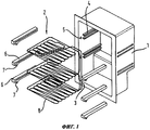
фигура 1: покомпонентное изображение холодильной полости холодильного аппарата согласно изобретению.figure 1: exploded view of the refrigeration cavity of a refrigerator according to the invention.
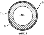
Фигура 2: разрез трубы испарителя с покрытием согласно изобретению.Figure 2: sectional view of a coated evaporator pipe according to the invention.
Осуществление изобретенияThe implementation of the invention
На фигуре 1 несколько трубных испарителей 2 соединено между собой в модульный трубный испаритель. Соединительные трубки 3, соединяющие отдельные трубные испарители 2, пролегают во внутреннем пространстве холодильного аппарата вдоль правой задней, вертикальной кромки холодильной полости 1.In figure 1,
В представленном здесь варианте исполнения модульный трубный испаритель составлен из трех различных трубных испарителей. На верхнем трубном испарителе предусмотрен ввод и вывод модульного трубного испарителя. Средний трубный испаритель имеет изогнутые вверх и вниз оконечности трубы. У нижнего трубного испарителя, напротив, обе оконечности трубы загнуты вверх. В холодильном аппарате с высокой холодильной полостью могут использоваться дополнительные уровни с трубными испарителями. Эти дополнительные трубные испарители будут иметь такую же конструкцию, что и средний трубный испаритель, то есть будут иметь изогнутые вверх и вниз оконечности трубы.In the embodiment presented here, the modular tube evaporator is composed of three different tube evaporators. An input and output of a modular pipe evaporator is provided on the upper tube evaporator. The middle tube evaporator has pipe ends bent up and down. At the lower pipe evaporator, on the contrary, both ends of the pipe are bent upwards. In a refrigerator with a high refrigeration cavity, additional levels with tube evaporators can be used. These additional tube evaporators will have the same design as the middle tube evaporator, that is, they will have pipe ends bent up and down.
Для фиксации трубы 8 испарителя и стабилизации трубного испарителя 2 по бокам каждого трубного испарителя 2 крепятся насадки 6. Такие насадки 6 позволяют ввести трубные испарители 2 в направляющие 4, предусмотренные в боковых стенках холодильной полости 1. Благодаря этому трубные испарители 2 фиксируются в холодильной полости 1 в своем вертикальном положении. Для фиксации труб по горизонтали насадки 6 содержат не показанные на фигуре выступы, входящие в зацепление с углублениями 5 в боковых стенках холодильной полости 1.To fix the
Кроме того, насадки 6 содержат направленные вниз упоры 7. Эти упоры 7 служат ограничителями для выдвижных контейнеров, которые используют верхнюю сторону насадок 6 в качестве поверхности скольжения. Высота выдвижных контейнеров выбирается таким образом, чтобы они проходили между отдельными трубными испарителями 2 с небольшим зазором. Контейнеры вводятся в слегка наклоненном положении, чтобы можно было завести заднюю стенку контейнера за упоры 7.In addition, the
При вставке контейнера эти упоры 7 служат для того, чтобы задняя стенка контейнера не прилегала к задней стенке холодильной полости 1, и между обеими задними стенками сохранялся необходимый воздушный зазор даже при полностью задвинутом контейнере. Это достигается за счет того, что упор 7 прилегает к передней стенке контейнера и препятствует дальнейшему задвиганию.When the container is inserted, these stops 7 serve to ensure that the rear wall of the container does not lie against the rear wall of the
Так как выдвижные контейнеры скользят не непосредственно по трубному испарителю 2, а по насадкам 6, труба испарителя не нуждается в износостойком и защитном покрытии; вместо этого покрытие можно выбирать по совершенно иным критериям. Поэтому, согласно изобретению, трубные испарители 2 покрываются так называемым лаком AFP 11 (антиобледенительным белковым лаком). Этим же лаком AFP покрываются соединительные трубки 3.Since the sliding containers do not slide directly along the
Конструкция трубы 8 испарителя показана на фигуре 2 в разрезе. Труба 8 испарителя обычно представляет собой металлическую трубу 9. Эта металлическая труба 9 изготавливается из материала, который легко поддается обработке, в частности, легко гнется и обладает хорошей теплопроводностью. Поэтому во многих холодильных аппаратах для изготовления трубы 8 испарителя используется алюминий. Металлическая труба 9 содержит канал 10 для хладагента.The design of the
На наружную сторону металлической трубы 9 нанесен лак AFP 11. Этот лак содержит белок, препятствующий образованию кристаллов льда. Следовательно, вода, которая хотя и конденсируется на трубе 8 испарителя из воздуха в холодильной полости 1, не переходит в кристаллическое состояние. Вода может собираться и выводиться наружу обычным, не показанным на фигуре способом. Снаружи она выводится в испарительный лоток, расположенный, например, на компрессоре, и отдается в окружающий воздух.
Следовательно, передача тепла от воздуха внутри холодильной полости 1 к хладагенту в канале 10 трубы 8 испарителя не ухудшается даже после длительной работы холодильного аппарата. Тем самым можно исключить повышение энергопотребления, обусловленное ухудшенной теплопередачей. Кроме того, прибор не нуждается в размораживании. После размораживания температура внутреннего пространства холодильного аппарата обычно равна температуре окружающего воздуха. Поэтому после каждого процесса размораживания температуру внутреннего пространства необходимо сначала снова опустить до нормального уровня. Для этого требуется значительное количество энергии. В холодильном аппарате согласно изобретению эту энергию можно экономить.Therefore, the heat transfer from the air inside the
Claims (6)
Applications Claiming Priority (3)
| Application Number | Priority Date | Filing Date | Title |
|---|---|---|---|
| DE102007047116.7 | 2007-10-02 | ||
| DE102007047116A DE102007047116A1 (en) | 2007-10-02 | 2007-10-02 | The refrigerator |
| PCT/EP2008/062079 WO2009047078A2 (en) | 2007-10-02 | 2008-09-11 | Refrigeration device |
Publications (2)
| Publication Number | Publication Date |
|---|---|
| RU2010114078A RU2010114078A (en) | 2011-11-10 |
| RU2473024C2 true RU2473024C2 (en) | 2013-01-20 |
Family
ID=40418030
Family Applications (1)
| Application Number | Title | Priority Date | Filing Date |
|---|---|---|---|
| RU2010114078/13A RU2473024C2 (en) | 2007-10-02 | 2008-09-11 | Refrigerating unit |
Country Status (6)
| Country | Link |
|---|---|
| US (1) | US20100199698A1 (en) |
| EP (1) | EP2195591B1 (en) |
| CN (1) | CN101809389B (en) |
| DE (1) | DE102007047116A1 (en) |
| RU (1) | RU2473024C2 (en) |
| WO (1) | WO2009047078A2 (en) |
Families Citing this family (3)
| Publication number | Priority date | Publication date | Assignee | Title |
|---|---|---|---|---|
| DE102009035453A1 (en) * | 2009-07-17 | 2011-01-20 | Liebherr-Hausgeräte Ochsenhausen GmbH | Refrigerator and/or freezer with a surface comprising an agent that comprises surface modifying proteins and/or polymers, and prevents or reduces the condensation, freezing and/or resublimation of moisture on the surface |
| CN108351150A (en) * | 2015-10-23 | 2018-07-31 | 开利公司 | Air temperature regulating system with frost prevention heat exchanger |
| US20220174908A1 (en) * | 2020-12-04 | 2022-06-09 | Summit Seeker Solutions LLC | Temperature Controlled Pet Bed System |
Citations (4)
| Publication number | Priority date | Publication date | Assignee | Title |
|---|---|---|---|---|
| FR2545915A1 (en) * | 1983-05-10 | 1984-11-16 | Bosch Siemens Hausgeraete | Single circuit refrigerator and freezer |
| SU1386630A1 (en) * | 1986-06-24 | 1988-04-07 | Специальное Конструкторско-Технологическое Бюро Отделения Химии Поверхности Института Физической Химии Ан Усср | Compound for anti-icing coating "krezan" |
| SU1712388A1 (en) * | 1990-01-18 | 1992-02-15 | Институт коллоидной химии и химии воды им.А.В.Думанского | Compound for anti-icing coat |
| JPH0587422A (en) * | 1991-09-27 | 1993-04-06 | Showa Alum Corp | Cooling panel with frost-preventive coat for evaporator |
Family Cites Families (10)
| Publication number | Priority date | Publication date | Assignee | Title |
|---|---|---|---|---|
| SE413805B (en) * | 1972-10-12 | 1980-06-23 | Electrolux Ab | DEVICE AT A FREEZER FOR FREEZING GOODS AND STORAGE OF FROZEN GOODS |
| US3828570A (en) | 1973-05-24 | 1974-08-13 | Niagara Blower Co | Heat exchange apparatus |
| GB2031498B (en) * | 1978-09-27 | 1982-11-10 | Teijin Ltd | Multi-pane window structure |
| US5263535A (en) * | 1992-06-15 | 1993-11-23 | White Consolidated Industries, Inc. | Evaporator coil mounting device |
| FR2794225B3 (en) * | 1999-05-25 | 2001-06-15 | Saint Gobain Vitrage | REFRIGERATED ENCLOSURE DOOR WITH VACUUM WINDOWS |
| WO2001094378A1 (en) * | 2000-06-08 | 2001-12-13 | The Research Foundation Of State University Of New York | Nucleic acid sequences encoding type iii tenebrio antifreeze proteins and method for assaying activity |
| DE10161306A1 (en) * | 2001-12-13 | 2003-06-26 | Bsh Bosch Siemens Hausgeraete | Method for controlling the moisture content of the air in a domestic frost-free refrigerator/freezer has a selector switch to vary the switching of the fan and compressor |
| WO2003080137A1 (en) * | 2002-03-26 | 2003-10-02 | Magnus Qvist | Method for attaching two surfaces to each other using a bioadhesive polyphenolic protein and periodate ions. |
| CN1317344C (en) * | 2004-12-17 | 2007-05-23 | 北京工业大学 | Hydrophilic antifrosting coating |
| JP2007173041A (en) * | 2005-12-22 | 2007-07-05 | Toyota Motor Corp | Fuel cell and electrolyte layer for fuel cell |
-
2007
- 2007-10-02 DE DE102007047116A patent/DE102007047116A1/en not_active Withdrawn
-
2008
- 2008-09-11 CN CN2008801096358A patent/CN101809389B/en not_active Expired - Fee Related
- 2008-09-11 EP EP08804044.9A patent/EP2195591B1/en not_active Not-in-force
- 2008-09-11 US US12/679,700 patent/US20100199698A1/en not_active Abandoned
- 2008-09-11 RU RU2010114078/13A patent/RU2473024C2/en active
- 2008-09-11 WO PCT/EP2008/062079 patent/WO2009047078A2/en active Application Filing
Patent Citations (4)
| Publication number | Priority date | Publication date | Assignee | Title |
|---|---|---|---|---|
| FR2545915A1 (en) * | 1983-05-10 | 1984-11-16 | Bosch Siemens Hausgeraete | Single circuit refrigerator and freezer |
| SU1386630A1 (en) * | 1986-06-24 | 1988-04-07 | Специальное Конструкторско-Технологическое Бюро Отделения Химии Поверхности Института Физической Химии Ан Усср | Compound for anti-icing coating "krezan" |
| SU1712388A1 (en) * | 1990-01-18 | 1992-02-15 | Институт коллоидной химии и химии воды им.А.В.Думанского | Compound for anti-icing coat |
| JPH0587422A (en) * | 1991-09-27 | 1993-04-06 | Showa Alum Corp | Cooling panel with frost-preventive coat for evaporator |
Also Published As
| Publication number | Publication date |
|---|---|
| EP2195591B1 (en) | 2017-12-06 |
| US20100199698A1 (en) | 2010-08-12 |
| CN101809389A (en) | 2010-08-18 |
| EP2195591A2 (en) | 2010-06-16 |
| CN101809389B (en) | 2013-07-10 |
| DE102007047116A1 (en) | 2009-04-09 |
| WO2009047078A3 (en) | 2009-07-30 |
| WO2009047078A2 (en) | 2009-04-16 |
| RU2010114078A (en) | 2011-11-10 |
Similar Documents
| Publication | Publication Date | Title |
|---|---|---|
| US9879896B2 (en) | Ice making system and method for a refrigerator | |
| CN107621114A (en) | A kind of wind cooling refrigerator | |
| CN102317716B (en) | Refrigerator | |
| EP3106798B1 (en) | Ice making system and method for a refrigerator | |
| RU2473024C2 (en) | Refrigerating unit | |
| CN210832693U (en) | Refrigerator with a door | |
| US20140150465A1 (en) | On-door ice maker cooling | |
| US20190219322A1 (en) | Multilayer pipe cooling cold storage | |
| US10180275B2 (en) | Ice making duct for refrigerator and ice making method using the same | |
| US20160370048A1 (en) | Ice making duct for refrigerator and ice making method of using the same | |
| US10180273B2 (en) | Ice making system and method for a refrigerator | |
| CN210220351U (en) | Single system refrigerator | |
| US5403609A (en) | Method and equipment for storing foodstuffs, plants, vegetables, meats and other organic substances | |
| KR101696893B1 (en) | Refrigerator and ice making method thereof | |
| JP4502897B2 (en) | refrigerator | |
| CN111109343A (en) | Method for widening ice temperature zone of food material by using space static and constant temperature technology | |
| CN112484370A (en) | Refrigerator with a door | |
| CN210220350U (en) | Single system refrigerator | |
| CN102317713B (en) | Refrigerator | |
| KR20100019080A (en) | Fan cover for refrigerator | |
| EP2846116B1 (en) | Refrigerator | |
| US20220154999A1 (en) | Refrigerator appliance auxiliary evaporation tray | |
| CN105276897A (en) | Refrigerator | |
| CN2660420Y (en) | Frostless refrigerator | |
| JP2000205710A (en) | Ice making machine |
Legal Events
| Date | Code | Title | Description |
|---|---|---|---|
| PD4A | Correction of name of patent owner |