RU2471237C2 - Creating models of reduced order of electromagnetic response signal from underground structure - Google Patents
Creating models of reduced order of electromagnetic response signal from underground structure Download PDFInfo
- Publication number
- RU2471237C2 RU2471237C2 RU2010140067/08A RU2010140067A RU2471237C2 RU 2471237 C2 RU2471237 C2 RU 2471237C2 RU 2010140067/08 A RU2010140067/08 A RU 2010140067/08A RU 2010140067 A RU2010140067 A RU 2010140067A RU 2471237 C2 RU2471237 C2 RU 2471237C2
- Authority
- RU
- Russia
- Prior art keywords
- model
- reduced order
- underground structure
- create
- imaginary
- Prior art date
Links
- 230000004044 response Effects 0.000 title claims abstract description 15
- 238000000034 method Methods 0.000 claims abstract description 30
- 238000004422 calculation algorithm Methods 0.000 claims description 8
- 230000009467 reduction Effects 0.000 claims description 7
- 230000003278 mimic effect Effects 0.000 claims description 2
- 239000000126 substance Substances 0.000 abstract 1
- 238000004364 calculation method Methods 0.000 description 7
- 230000008569 process Effects 0.000 description 6
- 238000005259 measurement Methods 0.000 description 5
- 238000013459 approach Methods 0.000 description 4
- 230000005672 electromagnetic field Effects 0.000 description 3
- 238000012986 modification Methods 0.000 description 3
- 230000004048 modification Effects 0.000 description 3
- 230000003595 spectral effect Effects 0.000 description 3
- XLYOFNOQVPJJNP-UHFFFAOYSA-N water Substances O XLYOFNOQVPJJNP-UHFFFAOYSA-N 0.000 description 3
- 238000009825 accumulation Methods 0.000 description 2
- 238000013480 data collection Methods 0.000 description 2
- 230000005684 electric field Effects 0.000 description 2
- 239000013505 freshwater Substances 0.000 description 2
- 239000011159 matrix material Substances 0.000 description 2
- 238000011160 research Methods 0.000 description 2
- 239000000523 sample Substances 0.000 description 2
- 239000004215 Carbon black (E152) Substances 0.000 description 1
- 230000008901 benefit Effects 0.000 description 1
- 230000001143 conditioned effect Effects 0.000 description 1
- 238000007796 conventional method Methods 0.000 description 1
- 238000000354 decomposition reaction Methods 0.000 description 1
- 238000010586 diagram Methods 0.000 description 1
- 229930195733 hydrocarbon Natural products 0.000 description 1
- 150000002430 hydrocarbons Chemical class 0.000 description 1
- 230000010354 integration Effects 0.000 description 1
- 238000011835 investigation Methods 0.000 description 1
- 238000013178 mathematical model Methods 0.000 description 1
- 230000035699 permeability Effects 0.000 description 1
- 238000012892 rational function Methods 0.000 description 1
- 238000004088 simulation Methods 0.000 description 1
- 238000001228 spectrum Methods 0.000 description 1
Images


Classifications
-
- G—PHYSICS
- G01—MEASURING; TESTING
- G01V—GEOPHYSICS; GRAVITATIONAL MEASUREMENTS; DETECTING MASSES OR OBJECTS; TAGS
- G01V3/00—Electric or magnetic prospecting or detecting; Measuring magnetic field characteristics of the earth, e.g. declination, deviation
- G01V3/12—Electric or magnetic prospecting or detecting; Measuring magnetic field characteristics of the earth, e.g. declination, deviation operating with electromagnetic waves
-
- G—PHYSICS
- G01—MEASURING; TESTING
- G01V—GEOPHYSICS; GRAVITATIONAL MEASUREMENTS; DETECTING MASSES OR OBJECTS; TAGS
- G01V3/00—Electric or magnetic prospecting or detecting; Measuring magnetic field characteristics of the earth, e.g. declination, deviation
- G01V3/08—Electric or magnetic prospecting or detecting; Measuring magnetic field characteristics of the earth, e.g. declination, deviation operating with magnetic or electric fields produced or modified by objects or geological structures or by detecting devices
- G01V3/083—Controlled source electromagnetic [CSEM] surveying
-
- G—PHYSICS
- G01—MEASURING; TESTING
- G01V—GEOPHYSICS; GRAVITATIONAL MEASUREMENTS; DETECTING MASSES OR OBJECTS; TAGS
- G01V20/00—Geomodelling in general
-
- G—PHYSICS
- G01—MEASURING; TESTING
- G01V—GEOPHYSICS; GRAVITATIONAL MEASUREMENTS; DETECTING MASSES OR OBJECTS; TAGS
- G01V3/00—Electric or magnetic prospecting or detecting; Measuring magnetic field characteristics of the earth, e.g. declination, deviation
- G01V3/18—Electric or magnetic prospecting or detecting; Measuring magnetic field characteristics of the earth, e.g. declination, deviation specially adapted for well-logging
- G01V3/30—Electric or magnetic prospecting or detecting; Measuring magnetic field characteristics of the earth, e.g. declination, deviation specially adapted for well-logging operating with electromagnetic waves
Landscapes
- Physics & Mathematics (AREA)
- Engineering & Computer Science (AREA)
- Remote Sensing (AREA)
- Life Sciences & Earth Sciences (AREA)
- Electromagnetism (AREA)
- Environmental & Geological Engineering (AREA)
- Geology (AREA)
- General Life Sciences & Earth Sciences (AREA)
- General Physics & Mathematics (AREA)
- Geophysics (AREA)
- Geophysics And Detection Of Objects (AREA)
- Management, Administration, Business Operations System, And Electronic Commerce (AREA)
Abstract
Description
ПЕРЕКРЕСТНЫЕ ССЫЛКИ НА РОДСТВЕННЫЕ ЗАЯВКИCROSS RELATIONS TO RELATED APPLICATIONS
По настоящей заявке США испрашивается приоритет предварительной заявки на патент США № 61/041001, поданной 31 марта 2008 г., которая включена в данный документ в качестве ссылки.This US application claims the priority of provisional patent application US No. 61/041001, filed March 31, 2008, which is incorporated herein by reference.
ОБЛАСТЬ ТЕХНИКИFIELD OF TECHNOLOGY
Настоящее изобретение относится, в общем, к созданию моделей приведенного порядка для моделирования электромагнитного отклика от подземной структуры.The present invention relates, in general, to the creation of reduced order models for modeling the electromagnetic response from an underground structure.
УРОВЕНЬ ТЕХНИКИBACKGROUND
Существуют различные способы электромагнитного исследования структур, находящихся под поверхностью земли, для идентификации структур, представляющих интерес. Примеры подземных структур, представляющих интерес, включают в себя подземные высокоомные объекты, такие как нефтесодержащие пласты-коллекторы, зоны скопления газа и водоносные слои пресной воды. Одна из методик разведки представляет собой технику магнитотеллурического (МТ) исследования, которая использует временные измерения электрических и магнитных полей (которые являются чувствительными к встречающимся электромагнитным полям) для определения распределения электрической проводимости под поверхностью земли. Другая методика разведки является техникой электромагнитного исследования управляемым источником (CSEM), в которой для генерации электромагнитных сигналов используется электромагнитный передатчик. В соответствии с любой методикой разведки на поверхности земли в интересующей зоне разворачиваются разведочные блоки (или приемники), содержащие датчики электрического и магнитного поля, для проведения измерений, из которых может быть извлечена информация по геофизической разведке подземных структур под поверхностью земли.There are various methods for electromagnetic investigation of structures below the surface of the earth to identify structures of interest. Examples of underground structures of interest include underground high-resistivity objects such as oily reservoirs, gas accumulation zones and freshwater aquifers. One of the reconnaissance techniques is a magnetotelluric (MT) technique, which uses temporary measurements of electric and magnetic fields (which are sensitive to electromagnetic fields encountered) to determine the distribution of electrical conductivity beneath the surface of the earth. Another reconnaissance technique is a controlled source electromagnetic research technique (CSEM), which uses an electromagnetic transmitter to generate electromagnetic signals. In accordance with any exploration technique, exploration blocks (or receivers) containing electric and magnetic field sensors are deployed on the surface of the earth in the zone of interest to carry out measurements, from which information on geophysical exploration of underground structures below the earth's surface can be extracted.
Чтобы разработать модели для моделирования ответного электромагнитного сигнала от подземных структур, часто производится прямое моделирование. Обычно прямое моделирование включает в себя создание математической модели, из которой могут быть получены "синтетические" (моделированные) электромагнитные данные. Затем синтетические электромагнитные данные сравниваются с реальными электромагнитными данными. Если синтетические данные и электромагнитные данные не совпадают внутри предопределенного критерия сходимости, то модель изменяется и вышеуказанный процесс повторяется, многократно, до тех пор, пока не будет достигнуто удовлетворительное совпадение между синтетическими данными и электромагнитными данными.In order to develop models for simulating an electromagnetic response from underground structures, direct modeling is often performed. Typically, direct modeling involves creating a mathematical model from which "synthetic" (simulated) electromagnetic data can be obtained. Synthetic electromagnetic data are then compared with real electromagnetic data. If the synthetic data and electromagnetic data do not coincide within the predetermined convergence criterion, then the model changes and the above process is repeated, many times, until a satisfactory agreement between the synthetic data and electromagnetic data is achieved.
Обычно прямая модель создается для относительно большого частотного диапазона (содержащего множество частот) и относительно большого временного интервала (содержащего множество временных точек). Это приводит к созданию относительно больших прямых моделей, которые из-за сложных вычислений трудно и просчитывать, и использовать.Typically, a direct model is created for a relatively large frequency range (containing many frequencies) and a relatively large time interval (containing many time points). This leads to the creation of relatively large direct models, which are difficult to calculate and use due to complex calculations.
СУЩНОСТЬ ИЗОБРЕТЕНИЯSUMMARY OF THE INVENTION
В общем, в соответствии с вариантом выполнения предложена методика создания прямой модели приведенного порядка ответного сигнала геофизической разведки от подземной структуры, модели, которая аппроксимирует истинную прямую модель по всему диапазону частот или временнóму интервалу.In general, in accordance with an embodiment, a technique is proposed for creating a direct model of the reduced order of the geophysical exploration response signal from an underground structure, a model that approximates a true direct model over the entire frequency range or time interval.
КРАТКОЕ ОПИСАНИЕ ЧЕРТЕЖЕЙBRIEF DESCRIPTION OF THE DRAWINGS
Другие или альтернативные признаки станут очевидными из следующего описания, из пунктов формулы изобретения, и чертежей, на которых:Other or alternative features will become apparent from the following description, from the claims, and the drawings, in which:
Фиг.1 изображает условную схему расположения оборудования для выполнения разведки подземной структуры, где может быть внедрен вариант реализации настоящего изобретения;Figure 1 depicts a conventional arrangement of equipment for performing exploration of an underground structure, where an embodiment of the present invention may be implemented;
Фиг.2 - блок-схема последовательности операций процесса создания прямой модели в соответствии с вариантом выполнения, которая представляет собой ответный сигнал геофизической разведки от подземной структуры;Figure 2 is a flowchart of a direct model creation process in accordance with an embodiment, which is a geophysical exploration response signal from an underground structure;
Фиг.3 - блок-схема примерной вычислительной системы, которая способна выполнить процесс по фиг.2.Figure 3 is a block diagram of an exemplary computing system that is capable of performing the process of figure 2.
ПОДРОБНОЕ ОПИСАНИЕ ИЗОБРЕТЕНИЯDETAILED DESCRIPTION OF THE INVENTION
В следующем далее описании для обеспечения понимания настоящего изобретения изложены многочисленные подробности. Однако для специалистов в данной области техники будет понятно, что настоящее изобретение может быть реализовано без этих подробностей и что возможны многочисленные изменения и модификации описанных вариантов исполнения.In the following description, numerous details are set forth in order to provide an understanding of the present invention. However, it will be understood by those skilled in the art that the present invention may be practiced without these details and that numerous changes and modifications of the described embodiments are possible.
Моделирование задач морской электромагнитной (ЭМ) геофизической разведки, таких как магнитотеллурическое зондирование и задач исследования с управляемым электромагнитным источником (CSEM), включает в себя получение решений для относительно больших диапазонов по частоте и временных интервалов. Некоторые варианты выполнения настоящего изобретения создают модели приведенного порядка для точной аппроксимации истинных прямых моделей по всем частотным диапазонам и временным интервалам с относительно низкой стоимостью компьютерных вычислений. Модель приведенного порядка представляет собой приблизительную прямую модель, которая моделирует ответный сигнал подземной структуры на зондирующий сигнал, такой как электромагнитный сигнал, сгенерированный электромагнитным передатчиком, естественно возникающий электромагнитный сигнал или сейсмический сигнал. Модель приведенного порядка может быть использована для формирования синтетических данных, которые представляют собой имитационную версию ожидаемого ответного сигнала подземной структуры на данный входной сигнал.Modeling marine electromagnetic (EM) geophysical exploration tasks such as magnetotelluric sounding and controlled electromagnetic source (CSEM) research tasks involves obtaining solutions for relatively large frequency ranges and time intervals. Some embodiments of the present invention create reduced-order models for accurately approximating true direct models over all frequency ranges and time intervals with a relatively low cost of computer calculations. The reduced order model is an approximate direct model that models the response of an underground structure to a probing signal, such as an electromagnetic signal generated by an electromagnetic transmitter, a naturally occurring electromagnetic signal, or a seismic signal. The reduced order model can be used to generate synthetic data, which is a simulated version of the expected response of the underground structure to a given input signal.
Некоторые варианты выполнения использовались для разработки быстрого и надежного числового алгоритма, основанного на общих подходах приведения модели, которые, в свою очередь, основаны на оптимальном выборе частот интерполяции. В некоторых вариантах выполнения частоты интерполяции выбираются такими, чтобы были полностью мнимыми (недействительными) частотами для повышения эффективности решения для моделей приведенного порядка. Под частотами интерполяции имеются в виду такие частоты, при которых получают решения, которые строят (охватывают) пространство, называемое рациональным подпространством Крылова. Для задач частотной области модель приведенного порядка строится с использованием проекции Галеркина на рациональное подпространство Крылова.Some embodiments were used to develop a fast and reliable numerical algorithm based on general approaches to model reduction, which, in turn, are based on the optimal choice of interpolation frequencies. In some embodiments, the interpolation frequencies are chosen so that they are completely imaginary (invalid) frequencies to increase the efficiency of the solution for reduced order models. By interpolation frequencies we mean frequencies at which solutions are obtained that build (cover) a space called the rational Krylov subspace. For frequency domain problems, a reduced order model is constructed using the Galerkin projection on the rational Krylov subspace.
Несколько задач частотной области для выбранных частот интерполяции решены с использованием средств решения с введенными предварительными условиями. При этом образовано рациональное подпространство Крылова, охватывающее такие решения, и решена задача Галеркина. Выбором чисто мнимых частот интерполяции основные вычисления для получения модели приведенного порядка могут быть выполнены с использованием действительной арифметики, что значительно сокращает стоимость вычислений по сравнению с моделированиями обычной частотной области с использованием интегрирования по контуру. Подход к решению задачи получения модели приведенного порядка на основе выбора чисто мнимых частот интерполяции может быть распространен также и на задачи временнóго интервала. Исключительное аппроксимирующее свойство рационального подпространства Крылова применительно к технике приведения модели позволяет значительно сократить размеры подпространства по сравнению с размером стандартного (полиномиального) подпространства Крылова, используемого в обычных методах, например в методе спектрального разложения Ланчоса (Lanczos).Several frequency-domain problems for the selected interpolation frequencies have been solved using the solution tools with the preconditions introduced. In this case, a rational Krylov subspace is formed, covering such solutions, and the Galerkin problem is solved. By choosing purely imaginary interpolation frequencies, the basic calculations for obtaining a reduced order model can be performed using real arithmetic, which significantly reduces the cost of calculations compared to simulations of the usual frequency domain using contour integration. An approach to solving the problem of obtaining a reduced order model based on the choice of purely imaginary interpolation frequencies can also be extended to time interval problems. The exceptional approximating property of the rational Krylov subspace as applied to the model reduction technique allows one to significantly reduce the size of the subspace compared to the size of the standard (polynomial) Krylov subspace used in conventional methods, for example, the Lanczos spectral decomposition method.
Фиг.1 показывает примерную схему расположения оборудования для выполнения разведки подземной структуры в морских условиях. Как показано на фиг.1, электромагнитная разведка с управляемым источником выполняется относительно подземной структуры 100, которая расположена под поверхностью 102 водного дна (например, морского дна). Подземная структура 100 включает в себя один или большее количество представляющих интерес подземных элементов 104, причем один или большее количество подземных элементов может включать в себя месторождение углеводородов, зону скопления газа, водоносный слой пресной воды или другие представляющие интерес элементы. Управляемый электромагнитный источник (передатчик) 106 буксируется морским судном 108 на буксировочном тросе 110. Расположенный на судне контроллер 112 может посылать на управляемый источник 106 сигналы управления для включения этого управляемого электромагнитного источника и излучения им электромагнитного поля, которое через толщу воды 114 проникает в подземную структуру 100.Figure 1 shows an exemplary arrangement of equipment for performing exploration of an underground structure in marine conditions. As shown in FIG. 1, controlled-source electromagnetic intelligence is performed relative to the
На поверхности 102 водного дна установлена цепь или группа электромагнитных приемников 116, в которой эти электромагнитные приемники 116 могут детектировать электромагнитные поля, искаженные подземной структурой 100. Электромагнитные приемники 116 включают в себя чувствительные элементы для детектирования магнитных и/или электрических полей.A circuit or group of
В некоторый момент собранные электромагнитными приемниками 116 данные электромагнитной разведки передаются на установленный на морском судне 108 контроллер 112 или на удаленный контроллер.At some point, the electromagnetic intelligence data collected by the
Полученные электромагнитными приемниками 116 данные разведки накапливаются во времени; эти данные разведки предоставляются контроллеру 112 в виде временных последовательностей. Следует заметить, что передаваемый электромагнитным передатчиком 106 сигнал также записывается контроллером 112 в виде временных последовательностей.The intelligence obtained by
Хотя в вышеупомянутом варианте выполнения используется сигнал источника, генерируемый электромагнитным передатчиком 106, следует заметить, что в соответствии с некоторыми вариантами выполнения эти способы могут быть использованы в контексте магнитотеллурической разведки, в которой электромагнитные приемники 116 измеряют ответный сигнал подземных структур на возникающее природное магнитное поле. В качестве еще одной альтернативы варианты исполнения настоящего изобретения могут быть применимы и в контексте сейсмической разведки, где вместо электромагнитного передатчика 106 используется сейсмический источник для генерации сейсмических сигналов, которые распространяются в подземной структуре 100. Затем для измерения сейсмических сигналов, отраженных от подземной структуры 100, используются сейсмические приемники (вместо электромагнитных приемников 116). В этом альтернативном варианте выполнения сигнал сейсмического источника, посланный сейсмическим источником, также может быть записан в виде временных последовательностейAlthough the aforementioned embodiment uses a source signal generated by an
Более того, хотя фиг.1 показывает морскую систему сбора геофизических данных, следует заметить, что может быть реализовано альтернативное выполнение в виде наземной системы сбора геофизических данных. В наземной системе сбора данных могут быть использованы способы в соответствии с некоторыми вариантами исполнения настоящего изобретения.Moreover, although FIG. 1 shows a marine geophysical data collection system, it should be noted that an alternative embodiment in the form of a ground-based geophysical data collection system can be implemented. In a ground-based data acquisition system, methods may be used in accordance with some embodiments of the present invention.
Созданная в соответствии с некоторыми вариантами выполнения настоящего изобретения прямая модель приведенного порядка используется для моделирования ответного сигнала от подземной структуры 100 в ответ на входной зондирующий сигнал, такой как зондирующий сигнал, сгенерированный электромагнитным передатчиком 106.The direct reduced model created in accordance with some embodiments of the present invention is used to model a response signal from the
Далее представлена некоторая сопутствующая информация, предшествующая описанию алгоритма создания прямой модели приведенного порядка. Рассмотрим следующие уравнения Максвелла для частотной области в трехмерном (3D) пространстве R 3 с переменными коэффициентами в трехмерном пространстве:The following is some related information that precedes the description of the algorithm for creating a direct model of the reduced order. Consider the following Maxwell equations for the frequency domain in three-dimensional (3D) space R 3 with variable coefficients in three-dimensional space:
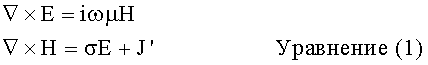
с однородными граничными условиями в бесконечности. Здесь i представляет мнимую единицу, Е - вектор электрического поля, H - вектор магнитного поля, индуцированного внешним током J' (ток электромагнитного передатчика, используемого в электромагнитной разведке), ω - частота, μ - магнитная проницаемость, которая предполагается постоянной по всей области, а σ - анизотропная электрическая проводимость (также полагается постоянной).with homogeneous boundary conditions at infinity. Here i represents the imaginary unit, E is the vector of the electric field, H is the vector of the magnetic field induced by the external current J ' (current of the electromagnetic transmitter used in electromagnetic reconnaissance), ω is the frequency, μ is the magnetic permeability, which is assumed to be constant over the entire region, and σ is the anisotropic electrical conductivity (also assumed to be constant).
Выражение для магнитного поля имеет вид:The expression for the magnetic field has the form:
![]()
![]()
гдеWhere
![]()
![]()
![]()
![]()
I - оператор тождества.I is the identity operator.
В вышеприведенных уравнениях Н, J', μ и σ - известные величины, основанные на полученных полевых измерениях (использующие схему разведки, представленную на фиг.1).In the above equations, H, J ′ , μ, and σ are known values based on the obtained field measurements (using the intelligence scheme shown in FIG. 1).
Выражение для временнóй области для магнитного поля имеет вид:The expression for the time domain for the magnetic field has the form:

Рассмотрим вычисление прямой модели f(A)b, где f - аналитическая функция в области D, и предположим, что спектр А принадлежит к области D. Для области частоты f(A)=(A-iωI)-1, а для области времени f(A)=е-tA.Consider the calculation of the direct model f (A) b , where f is an analytic function in the domain D, and suppose that the spectrum A belongs to the domain D. For the frequency domain f (A) = (A-iωI) -1 , and for the time domain f (A) = e -tA .
Подход приведенной модели связан с созданием приближения к f(A)b, которое является точным и легко вычисляется. При этом предполагается, что A и b являются, соответственно, дискретным оператором и источником, то есть A € R N×N и b € R N. Обычно модели приведенного порядка создаются с применением техники проецирования в заданное подпространство Кn низкой размерности n<<N. Полагая, что V есть ортогональная матрица с базисом в таком подпространствеThe approach of this model is associated with the creation of an approximation to f (A) b , which is accurate and easy to calculate. It is assumed that A and b are, respectively, a discrete operator and source, that is, A € R N × N and b € R N. Typically, reduced order models are created using the projection technique into a given subspace K n of low dimension n << N. Assuming that V is an orthogonal matrix with basis in such a subspace
![]()
![]()
где Н=V*AV.where H = V * AV.
Уравнение (6) представляет собой проекцию Галеркина в подпространство Кn. Для задачи частотной области вычисление f(Н) ведет к очень быстрой инверсии n раз n матриц ν, поскольку n мало. Для задачи временнóй области ниже будет показано, чтоEquation (6) is the projection of Galerkin into the subspace K n . For the frequency domain problem, computing f (H) leads to a very fast inversion of n times n matrices ν, since n is small. For the time domain problem, it will be shown below that
![]()
![]()
где (λi; zi)n i=1 есть собственные пары матриц Н: Azi=λizi.where (λi; zi) n i = 1 are the eigenpairs of the matrices H: Az i = λ i z i .
Снова, поскольку n мало, решение этой задачи собственного значения с точки зрения вычисления недорогое. Разница между различными проекционными методами состоит в выборе пространства проекции Кn.Again, since n is small, the solution to this eigenvalue problem is inexpensive from the point of view of computation. The difference between the various projection methods is the choice of the projection space K n .
В соответствии с некоторыми вариантами выполнения модель приведенного порядка построена выполнением проекции Галеркина в соответствии с уравнением (6) на рациональное подпространство Крылова, которое может быть представлено как Кn=span{(u j=(A-iωjI)-1 b}n j=1, которое представляет собой подпространство, охватывающее решения с интерполяционными не совпадающими чисто мнимыми частотами ωj. В соответствии с уравнением (6) проекция Галеркина относится к наилучшей аппроксимации Кn для другой частоты (отличной от мнимых интерполяционных частот ωj) или для решения задачи временнóй области. Следует заметить, что в частотной области метод проекции Галеркина дает точное решение на частотах, равных интерполяционным частотам.In accordance with some variants of execution, the reduced order model is constructed by performing the Galerkin projection in accordance with equation (6) on the rational Krylov subspace, which can be represented as K n = span {( u j = (A-iω j I) -1 b } n j = 1, which is a subspace covering solutions with interpolating mismatched purely imaginary frequencies ω j . According to equation (6), the Galerkin projection refers to the best approximation of K n for a different frequency (different from imaginary interpolation frequencies ω j ) or to solve the problem of the time domain It should be noted that in the frequency domain the Galerkin projection method gives an exact solution at frequencies equal to interpolation frequencies.
Если, в соответствии с некоторыми вариантами выполнения, сделать ωj полностью мнимыми, то iωj становятся вещественными, в результате вычисление (A-iωjI)-1 b в уравнении (2) может быть выполнено в действительной арифметике, что с вычислительной точки зрения обеспечивает значительное преимущество, поскольку оно приводит к решению вещественных симметричных линейных систем. Заметим, что A представляет собой вещественную симметричную матрицу, поэтому вычисление выражения (A-iωjI)-1 b выполняется решением вещественной симметричной линейной системы. Решение вещественной симметричной линейной системы может быть выполнено, используя обусловленный метод сопряженных градиентов, который значительно быстрее, чем решение комплексных симметричных линейных систем как в традиционном подходе к задаче частотной области с вещественными частотами.If, in accordance with some variants of execution, ω j is made completely imaginary, then iω j become real, as a result, the calculation of (A-iω j I) -1 b in equation (2) can be performed in real arithmetic, which is from a computational point vision provides a significant advantage, since it leads to the solution of real symmetric linear systems. Note that A is a real symmetric matrix, therefore, the expression (A-iω j I) -1 b is calculated by solving a real symmetric linear system. The solution of a real symmetric linear system can be performed using the conditioned method of conjugate gradients, which is much faster than the solution of complex symmetric linear systems as in the traditional approach to the problem of the frequency domain with real frequencies.
Кроме того, iωj выбраны как так называемые узлы Золотарева для данного спектрального интервала A. Узлы Золотарева представляют собой точки интерполяции для какого-то количества оптимальных рациональных приближений. Аппроксимационное решение получения модели приведенного порядка может рассматриваться как рациональное приближение в спектральном интервале A, то есть проекции решения собственных векторов интервала A являются рациональными функциями соответствующих собственных величин.In addition, iω j were chosen as the so-called Zolotarev nodes for a given spectral interval A. Zolotarev nodes represent interpolation points for a certain number of optimal rational approximations. The approximation solution for obtaining a reduced order model can be considered as a rational approximation in the spectral interval A, i.e., projections of the solution of the eigenvectors of the interval A are rational functions of the corresponding eigenvalues.
Фиг.2 иллюстрирует примерную блок-схему процесса создания модели приведенного порядка в соответствии с одним вариантом выполнения. Процесс может быть выполнен вычислительной системой, такой как вычислительная система, показанная на фиг.3.Figure 2 illustrates an exemplary flowchart of a process for creating a reduced order model in accordance with one embodiment. The process may be performed by a computing system, such as the computing system shown in FIG. 3.
Вычислительная система выбирает (на этапе 202) n мнимых частот интерполяции ωj, j=от 1 до n. На основании выбранных частот интерполяции создается (на этапе 204) рациональное подпространство Крылова Кn, где рациональное подпространство Крылова Кn охватывает решения с мнимыми интерполяционными частотами.The computing system selects (at 202) n imaginary interpolation frequencies ω j , j = 1 to n. Based on the selected interpolation frequencies, a rational Krylov subspace K n is created (at step 204), where the rational Krylov subspace K n covers solutions with imaginary interpolation frequencies.
Затем вычислительная система выполняет (на этапе 206) проекцию Галеркина на рациональное подпространство Крылова Кn для создания модели приведенного порядка. Делая это, поскольку выбраны мнимые интерполяционные частоты, эти вычислениями решается вещественная симметричная система для вычисления (A-iωjI)-1 b.Then the computing system performs (at step 206) Galerkin's projection onto the rational Krylov subspace K n to create a reduced order model. By doing this, since the imaginary interpolation frequencies are chosen, these calculations solve a real symmetric system to calculate (A-iω j I) -1 b .
Вышеописанный алгоритм дает общее описание алгоритма приведения модели, по которому создается такая модель приведенного порядка, которая аппроксимирует истинную прямую модель подземной структуры. По окончании создания модели приведенного порядка она может быть использована для получения синтетических данных, которые имитируют ответ подземной структуры на зондирующий сигнал.The above algorithm gives a general description of the model reduction algorithm, according to which such a reduced order model is created that approximates the true direct model of the underground structure. Upon completion of the creation of a reduced order model, it can be used to obtain synthetic data that mimic the response of an underground structure to a sounding signal.
Процесс по фиг.2 может быть выполнен показанной на фиг.3 вычислительной системой 300. Вычислительная система 300 включает в себя программное обеспечение 302, исполняемое на центральных процессорах 304, которые связаны с запоминающим устройством 306.The process of FIG. 2 may be performed by the computing system 300 shown in FIG. 3. The computing system 300 includes
Запоминающее устройство 306 используется для сохранения прямой модели 308 (модель приведенного порядка, созданная в соответствии с некоторыми вариантами исполнения). Запоминающее устройство 306 хранит также данные 310 измерений, такие как данные по измерениям электрических и/или магнитных полей, к которым может иметь доступ вычислительное программное обеспечение 302 для создания прямой модели 308.A storage device 306 is used to store a direct model 308 (a reduced order model created in accordance with some embodiments). The storage device 306 also stores
Хотя настоящее изобретение было раскрыто, исходя из ограниченного количества вариантов выполнения, специалистам в данной области техники, ознакомившимся с настоящим описанием, будут очевидны следующие из него многочисленные модификации и изменения. Приложенные пункты формулы изобретения предназначены для охвата таких модификации и изменений как соответствующих сущности и объему изобретения.Although the present invention has been disclosed on the basis of a limited number of embodiments, those skilled in the art who have become familiar with the present description will appreciate the numerous modifications and changes that come from it. The appended claims are intended to cover such modifications and changes as are appropriate to the spirit and scope of the invention.
Claims (8)
Applications Claiming Priority (5)
| Application Number | Priority Date | Filing Date | Title |
|---|---|---|---|
| US4100108P | 2008-03-31 | 2008-03-31 | |
| US61/041,001 | 2008-03-31 | ||
| US12/356,562 | 2009-01-21 | ||
| US12/356,562 US9529110B2 (en) | 2008-03-31 | 2009-01-21 | Constructing a reduced order model of an electromagnetic response in a subterranean structure |
| PCT/US2009/039017 WO2009146041A1 (en) | 2008-03-31 | 2009-03-31 | Constructing a reduced order model of an electromagnetic response in a subterranean structure |
Publications (2)
| Publication Number | Publication Date |
|---|---|
| RU2010140067A RU2010140067A (en) | 2012-05-10 |
| RU2471237C2 true RU2471237C2 (en) | 2012-12-27 |
Family
ID=41118452
Family Applications (1)
| Application Number | Title | Priority Date | Filing Date |
|---|---|---|---|
| RU2010140067/08A RU2471237C2 (en) | 2008-03-31 | 2009-03-31 | Creating models of reduced order of electromagnetic response signal from underground structure |
Country Status (4)
| Country | Link |
|---|---|
| US (1) | US9529110B2 (en) |
| EP (1) | EP2260461B1 (en) |
| RU (1) | RU2471237C2 (en) |
| WO (1) | WO2009146041A1 (en) |
Families Citing this family (20)
| Publication number | Priority date | Publication date | Assignee | Title |
|---|---|---|---|---|
| US9529110B2 (en) | 2008-03-31 | 2016-12-27 | Westerngeco L. L. C. | Constructing a reduced order model of an electromagnetic response in a subterranean structure |
| US8019548B2 (en) * | 2008-07-02 | 2011-09-13 | Westerngeco L. L. C. | Enabling analysis of a survey source signal using a time-based visualization of the survey source signal |
| US9134454B2 (en) | 2010-04-30 | 2015-09-15 | Exxonmobil Upstream Research Company | Method and system for finite volume simulation of flow |
| AU2011283196B2 (en) | 2010-07-29 | 2014-07-31 | Exxonmobil Upstream Research Company | Method and system for reservoir modeling |
| CA2805446C (en) | 2010-07-29 | 2016-08-16 | Exxonmobil Upstream Research Company | Methods and systems for machine-learning based simulation of flow |
| US10087721B2 (en) | 2010-07-29 | 2018-10-02 | Exxonmobil Upstream Research Company | Methods and systems for machine—learning based simulation of flow |
| EP2599031A4 (en) | 2010-07-29 | 2014-01-08 | Exxonmobil Upstream Res Co | Methods and systems for machine-learning based simulation of flow |
| BR112013002114A2 (en) | 2010-09-20 | 2016-05-17 | Exxonmobil Upstream Res Co | flexible and adaptable formulations for complex reservoir simulations |
| US20120259792A1 (en) * | 2011-04-06 | 2012-10-11 | International Business Machines Corporation | Automatic detection of different types of changes in a business process |
| BR112014005794A2 (en) | 2011-09-15 | 2017-03-28 | Exxonmobil Upstream Res Co | optimized matrix and vector operations in limited instruction algorithms that perform equation of state calculations |
| EP2901363A4 (en) | 2012-09-28 | 2016-06-01 | Exxonmobil Upstream Res Co | Fault removal in geological models |
| CA2948667A1 (en) | 2014-07-30 | 2016-02-04 | Exxonmobil Upstream Research Company | Method for volumetric grid generation in a domain with heterogeneous material properties |
| US10990713B1 (en) * | 2014-08-13 | 2021-04-27 | Ansys, Inc. | Systems and methods for fast matrix decomposition in model generation |
| US10803534B2 (en) | 2014-10-31 | 2020-10-13 | Exxonmobil Upstream Research Company | Handling domain discontinuity with the help of grid optimization techniques |
| CA2963092C (en) | 2014-10-31 | 2021-07-06 | Exxonmobil Upstream Research Company | Methods to handle discontinuity in constructing design space for faulted subsurface model using moving least squares |
| EP3485404B1 (en) * | 2016-07-18 | 2023-11-01 | Indian Institute of Science | Eigen augmentation methods for electromagnetic modelling and simulation |
| CN108072899B (en) * | 2016-11-10 | 2020-09-15 | 中国石油化工股份有限公司 | Self-adaptive implementation method of discontinuous Galerkin finite element seismic numerical simulation algorithm |
| WO2018118374A1 (en) | 2016-12-23 | 2018-06-28 | Exxonmobil Upstream Research Company | Method and system for stable and efficient reservoir simulation using stability proxies |
| RU2645864C1 (en) * | 2017-01-30 | 2018-02-28 | Закрытое акционерное общество "Аэрогеофизическая разведка" | Method of electrical examination with optimization of the observation system aperture |
| CN110119808A (en) * | 2018-02-06 | 2019-08-13 | 华为技术有限公司 | A kind of data processing method and relevant device based on machine learning |
Citations (5)
| Publication number | Priority date | Publication date | Assignee | Title |
|---|---|---|---|---|
| RU2145101C1 (en) * | 1999-02-16 | 2000-01-27 | Миколаевский Эрнест Юлианович | Method for estimation of service properties of gas-oil pool |
| RU2004116907A (en) * | 2004-06-03 | 2005-11-10 | Мурманский Государственный Технический Университет (Ru) | METHOD FOR CONSTRUCTING A REVERSABLE THREE-DIMENSIONAL HYDRODYNAMIC MODEL OF THE EARTH CALIBRATED IN REAL TIME DURING DRILLING |
| RU2300126C1 (en) * | 2006-03-29 | 2007-05-27 | ОАО "НК "Роснефть" | Mode of geophysical exploration for exposure of small amplitude tectonic abnormalities of oil-gas productive rocks in three-dimensional space |
| RU2300786C2 (en) * | 2002-01-04 | 2007-06-10 | Вестернджеко, Л.Л.С. | Method for measurement of running times for final-frequency seismic migration on monochromatic wave fields |
| WO2008005690A2 (en) * | 2006-06-21 | 2008-01-10 | Terraspark Geosciences, L.P. | Interpretation of geologic depositional systems |
Family Cites Families (18)
| Publication number | Priority date | Publication date | Assignee | Title |
|---|---|---|---|---|
| US5583825A (en) * | 1994-09-02 | 1996-12-10 | Exxon Production Research Company | Method for deriving reservoir lithology and fluid content from pre-stack inversion of seismic data |
| GB2324158B (en) * | 1996-12-04 | 2001-03-14 | Schlumberger Ltd | Method and apparatus for solving 3D Maxwell equations for inductive logging applications |
| FR2759473B1 (en) * | 1997-02-12 | 1999-03-05 | Inst Francais Du Petrole | METHOD FOR SIMPLIFYING THE REALIZATION OF A SIMULATION MODEL OF A PHYSICAL PROCESS IN A MATERIAL MEDIUM |
| GB9818875D0 (en) * | 1998-08-28 | 1998-10-21 | Norske Stats Oljeselskap | Method and apparatus for determining the nature of subterranean reservoirs |
| US6687658B1 (en) * | 1998-09-01 | 2004-02-03 | Agere Systems, Inc. | Apparatus and method for reduced-order modeling of time-varying systems and computer storage medium containing the same |
| FR2798197B1 (en) * | 1999-09-02 | 2001-10-05 | Inst Francais Du Petrole | METHOD FOR FORMING A MODEL OF A GEOLOGICAL FORMATION, CONSTRAINED BY DYNAMIC AND STATIC DATA |
| GB2390904B (en) * | 2002-07-16 | 2004-12-15 | Univ Southampton | Electromagnetic surveying for hydrocarbon reservoirs |
| US6819628B2 (en) * | 2003-04-07 | 2004-11-16 | Paradigm Geophysical (Luxembourg) S.A.R.L. | Wave migration by a krylov space expansion of the square root exponent operator, for use in seismic imaging |
| CN1973110A (en) * | 2004-06-25 | 2007-05-30 | 国际壳牌研究有限公司 | Closed loop control system for controlling production of hydrocarbon fluid from an underground formation |
| US7643942B2 (en) * | 2005-06-10 | 2010-01-05 | Exxonmobil Upstream Research Company | Method for controlled source electromagnetic reconnaissance surveying |
| US7324899B2 (en) * | 2005-07-22 | 2008-01-29 | University Of Utah | Geophysical technique for mineral exploration and discrimination based on electromagnetic methods and associated systems |
| GB2438430B (en) * | 2006-05-22 | 2008-09-17 | Ohm Ltd | Electromagnetic surveying |
| US7860655B2 (en) * | 2006-07-14 | 2010-12-28 | Westerngeco L.L.C. | Electromagnetically detecting thin resistive bodies in shallow water and terrestrial environments |
| US7474101B2 (en) * | 2006-09-12 | 2009-01-06 | Kjt Enterprises, Inc. | Method for combined transient and frequency domain electromagnetic measurements |
| US20090306943A1 (en) * | 2006-10-05 | 2009-12-10 | North Carolina State University | Methods, systems and computer program products for reduced order model adaptive simulation of complex systems |
| US9529110B2 (en) | 2008-03-31 | 2016-12-27 | Westerngeco L. L. C. | Constructing a reduced order model of an electromagnetic response in a subterranean structure |
| AU2010245112B2 (en) * | 2009-04-27 | 2013-03-14 | Schlumberger Technology B.V. | Method for uncertainty quantification in the performance and risk assessment of a carbon dioxide storage site |
| EP2287852A1 (en) * | 2009-08-18 | 2011-02-23 | Areva NP | A computer implemented method for modelling a nuclear reactor core and a corresponding computer program product |
-
2009
- 2009-01-21 US US12/356,562 patent/US9529110B2/en not_active Expired - Fee Related
- 2009-03-31 WO PCT/US2009/039017 patent/WO2009146041A1/en not_active Ceased
- 2009-03-31 EP EP09755404.2A patent/EP2260461B1/en not_active Not-in-force
- 2009-03-31 RU RU2010140067/08A patent/RU2471237C2/en not_active IP Right Cessation
Patent Citations (5)
| Publication number | Priority date | Publication date | Assignee | Title |
|---|---|---|---|---|
| RU2145101C1 (en) * | 1999-02-16 | 2000-01-27 | Миколаевский Эрнест Юлианович | Method for estimation of service properties of gas-oil pool |
| RU2300786C2 (en) * | 2002-01-04 | 2007-06-10 | Вестернджеко, Л.Л.С. | Method for measurement of running times for final-frequency seismic migration on monochromatic wave fields |
| RU2004116907A (en) * | 2004-06-03 | 2005-11-10 | Мурманский Государственный Технический Университет (Ru) | METHOD FOR CONSTRUCTING A REVERSABLE THREE-DIMENSIONAL HYDRODYNAMIC MODEL OF THE EARTH CALIBRATED IN REAL TIME DURING DRILLING |
| RU2300126C1 (en) * | 2006-03-29 | 2007-05-27 | ОАО "НК "Роснефть" | Mode of geophysical exploration for exposure of small amplitude tectonic abnormalities of oil-gas productive rocks in three-dimensional space |
| WO2008005690A2 (en) * | 2006-06-21 | 2008-01-10 | Terraspark Geosciences, L.P. | Interpretation of geologic depositional systems |
Also Published As
| Publication number | Publication date |
|---|---|
| WO2009146041A1 (en) | 2009-12-03 |
| RU2010140067A (en) | 2012-05-10 |
| EP2260461A1 (en) | 2010-12-15 |
| US20090248373A1 (en) | 2009-10-01 |
| EP2260461B1 (en) | 2015-02-25 |
| EP2260461A4 (en) | 2012-03-28 |
| US9529110B2 (en) | 2016-12-27 |
Similar Documents
| Publication | Publication Date | Title |
|---|---|---|
| RU2471237C2 (en) | Creating models of reduced order of electromagnetic response signal from underground structure | |
| US10310138B2 (en) | Accelerated Occam inversion using model remapping and Jacobian matrix decomposition | |
| Guo et al. | Application of supervised descent method for 2D magnetotelluric data inversion | |
| US20090083006A1 (en) | Methods and apparatus for three-dimensional inversion of electromagnetic data | |
| US10871590B2 (en) | Electromagnetic data inversion | |
| CA2749831C (en) | Stochastic inversion of geophysical data for estimating earth model parameters | |
| Sasaki et al. | Frequency and time domain three-dimensional inversion of electromagnetic data for a grounded-wire source | |
| Ellis | Inversion of airborne electromagnetic data | |
| Cai et al. | Effective 3D-transient electromagnetic inversion using finite-element method with a parallel direct solver | |
| US11215726B2 (en) | Inversion with exponentially encoded seismic data | |
| US8571842B2 (en) | Method of determining parameter from sparse measurement data | |
| Nguyen et al. | Comparing large-scale 3D Gauss–Newton and BFGS CSEM inversions | |
| Zhang et al. | MARE3DEM: A three-dimensional CSEM inversion based on a parallel adaptive finite element method using unstructured meshes | |
| Wang et al. | 2D joint inversion of CSAMT and magnetic data based on cross-gradient theory | |
| US11061159B2 (en) | Electromagnetic response data inversion using singular value decomposition | |
| US10571592B2 (en) | Direct resistivity determination | |
| Noh et al. | Three-dimensional inversion of CSEM data: Water leak detection using a small-loop EM method | |
| Bykov et al. | Approximation of equivalent transfer function of the geoelectric section in geodynamic inspection | |
| Li et al. | Inversion of controlled‐source electromagnetic data using a model‐based approach | |
| Kang et al. | mCSEM inversion for CO2 sequestration monitoring at a deep brine aquifer in a shallow sea | |
| Silva Crepaldi et al. | Fast marine CSEM inversion in the CMP domain using analytical derivatives | |
| GB2573152A (en) | Providing for uncertainty in non-linear inversions of geophysical data | |
| Yu et al. | A 2.5 D inversion of airborne electromagnetic data | |
| Schaa | Rapid approximate 3D inversion of transient electromagnetic data | |
| Liu et al. | Deep learning based one-dimensional inversion of magnetotelluric data, and an application in the southwestern Athabasca Basin, Canada |
Legal Events
| Date | Code | Title | Description |
|---|---|---|---|
| MM4A | The patent is invalid due to non-payment of fees |
Effective date: 20150401 |