RU2471083C2 - Drive for movable element of aircraft nacelle, and nacelle containing such drive - Google Patents
Drive for movable element of aircraft nacelle, and nacelle containing such drive Download PDFInfo
- Publication number
- RU2471083C2 RU2471083C2 RU2010117754/06A RU2010117754A RU2471083C2 RU 2471083 C2 RU2471083 C2 RU 2471083C2 RU 2010117754/06 A RU2010117754/06 A RU 2010117754/06A RU 2010117754 A RU2010117754 A RU 2010117754A RU 2471083 C2 RU2471083 C2 RU 2471083C2
- Authority
- RU
- Russia
- Prior art keywords
- slide
- engine
- nacelle
- specified
- drive
- Prior art date
Links
- 238000006073 displacement reaction Methods 0.000 claims abstract description 6
- 239000011521 glass Substances 0.000 claims description 11
- 238000009434 installation Methods 0.000 abstract description 7
- 239000000126 substance Substances 0.000 abstract 1
- 230000033001 locomotion Effects 0.000 description 7
- 230000008878 coupling Effects 0.000 description 2
- 238000010168 coupling process Methods 0.000 description 2
- 238000005859 coupling reaction Methods 0.000 description 2
- 238000000034 method Methods 0.000 description 2
- 101100327917 Caenorhabditis elegans chup-1 gene Proteins 0.000 description 1
- 230000005540 biological transmission Effects 0.000 description 1
Images


Classifications
-
- F—MECHANICAL ENGINEERING; LIGHTING; HEATING; WEAPONS; BLASTING
- F02—COMBUSTION ENGINES; HOT-GAS OR COMBUSTION-PRODUCT ENGINE PLANTS
- F02K—JET-PROPULSION PLANTS
- F02K1/00—Plants characterised by the form or arrangement of the jet pipe or nozzle; Jet pipes or nozzles peculiar thereto
- F02K1/54—Nozzles having means for reversing jet thrust
- F02K1/76—Control or regulation of thrust reversers
- F02K1/763—Control or regulation of thrust reversers with actuating systems or actuating devices; Arrangement of actuators for thrust reversers
-
- B—PERFORMING OPERATIONS; TRANSPORTING
- B64—AIRCRAFT; AVIATION; COSMONAUTICS
- B64D—EQUIPMENT FOR FITTING IN OR TO AIRCRAFT; FLIGHT SUITS; PARACHUTES; ARRANGEMENTS OR MOUNTING OF POWER PLANTS OR PROPULSION TRANSMISSIONS IN AIRCRAFT
- B64D29/00—Power-plant nacelles, fairings, or cowlings
- B64D29/06—Attaching of nacelles, fairings or cowlings
-
- F—MECHANICAL ENGINEERING; LIGHTING; HEATING; WEAPONS; BLASTING
- F16—ENGINEERING ELEMENTS AND UNITS; GENERAL MEASURES FOR PRODUCING AND MAINTAINING EFFECTIVE FUNCTIONING OF MACHINES OR INSTALLATIONS; THERMAL INSULATION IN GENERAL
- F16H—GEARING
- F16H25/00—Gearings comprising primarily only cams, cam-followers and screw-and-nut mechanisms
- F16H25/18—Gearings comprising primarily only cams, cam-followers and screw-and-nut mechanisms for conveying or interconverting oscillating or reciprocating motions
- F16H25/20—Screw mechanisms
- F16H2025/2037—Actuator supports or means for fixing piston end, e.g. flanges
Abstract
Description
Настоящее изобретение относится к приводу для подвижного элемента гондолы летательного аппарата и к гондоле, содержащей по меньшей мере один такой привод.The present invention relates to a drive for a movable member of an aircraft nacelle and to a nacelle comprising at least one such drive.
В европейском патенте ЕР 1239139, зарегистрированном на имя компании заявителя, раскрыт привод для подвижного элемента гондолы двигателя летательного аппарата, содержащий двигатель, устанавливаемый на неподвижном элементе указанной гондолы, червячный винт, который может приводиться во вращение этим двигателем, салазки, соединяемые с указанным подвижным элементом и содержащие гайку, находящуюся в зацеплении с указанным червячным винтом, и шаровой шарнир, благодаря которому возможно некоторое угловое смещение между осью указанного червячного винта и направлением перемещения указанных салазок.In European patent EP 1239139, registered in the name of the applicant company, a drive for a movable nacelle element of an aircraft engine is disclosed, comprising a motor mounted on a fixed element of said nacelle, a worm screw that can be rotated by this engine, a slide connected to said movable element and containing a nut engaged with said worm screw and a ball joint, due to which some angular displacement between the axis of said worm is possible screw and the direction of movement of the specified slide.
В данном известном приводе шаровой шарнир предохраняет вал двигателя и червячный винт от чрезмерного механического напряжения, возникающего при смещении салазок относительно оси двигателя.In this known drive, the ball joint protects the motor shaft and the worm screw from excessive mechanical stress arising when the slide is displaced relative to the motor axis.
Основная задача настоящего изобретения заключается в том, чтобы улучшить работу привода при таких осевых смещениях.The main objective of the present invention is to improve the operation of the drive at such axial displacements.
Другая задача настоящего изобретения заключается в том, чтобы предложить простое решение для установки гайки в салазках и облегчить процедуры установки и демонтажа подвижного элемента гондолы на ее неподвижном элементе.Another objective of the present invention is to provide a simple solution for installing the nut in the slide and to facilitate the installation and removal of the movable element of the nacelle on its fixed element.
Основная задача изобретения решена посредством привода для подвижного элемента гондолы двигателя летательного аппарата, содержащего двигатель, устанавливаемый на неподвижном элементе указанной гондолы, червячный винт, выполненный с возможностью приведения во вращение этим двигателем, салазки, присоединяемые к указанному подвижному элементу и содержащие гайку, находящуюся в зацеплении с указанным червячным винтом, и первый шаровой шарнир, допускающий некоторое угловое смещение между осью указанного червячного винта и указанными салазками. Данный привод отличается тем, что содержит стакан, выполненный с возможностью вмещения указанного винта и расположенный с зазором внутри указанных салазок. Указанная гайка установлена на конце указанного стакана, ближнем к указанному двигателю, и указанный первый шаровой шарнир вставлен между другим концом указанного стакана и указанными салазками.The main objective of the invention is solved by means of a drive for a movable element of a nacelle of an aircraft engine, comprising an engine mounted on a fixed element of said nacelle, a worm screw adapted to rotate by this engine, a slide attached to said movable element and containing a nut engaged with said worm screw and a first ball joint allowing some angular displacement between the axis of said worm screw and said ca azkami. This drive is characterized in that it contains a glass made with the possibility of accommodating the specified screw and located with a gap inside the specified slide. The specified nut is installed on the end of the specified glass, close to the specified engine, and the specified first ball joint is inserted between the other end of the specified glass and the specified slide.
Благодаря тому, что первый шаровой шарнир отделен от гайки и расположен в конце стакана, дальнем от двигателя, расстояние от двигателя до этого шарового шарнира всегда будет равно по меньшей мере длине червячного винта.Due to the fact that the first ball joint is separated from the nut and located at the end of the cup farthest from the engine, the distance from the engine to this ball joint will always be at least the length of the worm screw.
В результате удается минимизировать угол между осью червячного винта и направлением перемещения салазок, когда эти салазки отклоняются от оси двигателя, и за счет этого достичь уменьшения нагрузок, воздействующих на червячный винт, на двигатель и на сам подвижный элемент.As a result, it is possible to minimize the angle between the axis of the worm screw and the direction of movement of the slide when these slides deviate from the axis of the engine, and thereby reduce the loads acting on the screw, the engine and the movable element itself.
Следует также отметить, что установка гайки в стакан, который в свою очередь установлен внутри салазок, представляет собой простое решение установки гайки на салазки, осуществимое как для стандартных гаек, так и для гаек специальной конструкции (например, для шариковых гаек).It should also be noted that installing the nut in a cup, which in turn is installed inside the slide, is a simple solution to installing the nut on the slide, which is feasible for both standard nuts and nuts of a special design (for example, ball nuts).
Указанный привод может обладать также следующими дополнительными признаками:The specified drive may also have the following additional features:
- указанный первый шаровой шарнир помещен между указанным другим концом стакана и его опорой, расположенной внутри указанных салазок: эта опора является промежуточным элементом, облегчающим установку стакана внутри салазок;- the specified first ball joint is placed between the specified other end of the glass and its support located inside these rails: this support is an intermediate element that facilitates the installation of the glass inside the rails;
- указанная опора соединена с указанным стаканом съемной шпонкой: наличие этой шпонки облегчает процедуры установки и демонтажа опоры внутри салазок;- the specified support is connected to the specified glass with a removable key: the presence of this key facilitates the installation and dismantling of the support inside the slide;
- указанный первый шаровой шарнир соединен с указанной опорой съемным штифтом: наличие этого штифта облегчает процедуры установки и демонтажа первого шарового шарнира на опоре;- the specified first ball joint is connected to the indicated support with a removable pin: the presence of this pin facilitates the installation and dismantling of the first ball joint on the support;
- указанный привод содержит второй шаровой шарнир, помещенный между указанным двигателем и указанным червячным винтом: наличие этого второго шарового шарнира способствует повышению гибкости соединения двигателя с салазками, освобождая червячный винт и, в особенности, двигатель от нагрузок, которые могут быть созданы при отклонениях салазок от оси двигателя;- the specified drive contains a second ball joint placed between the specified engine and the specified worm screw: the presence of this second ball joint increases the flexibility of connecting the motor to the slide, freeing the screw screw and, in particular, the motor from the loads that can be created when the slides deviate from engine axis;
- указанный второй шаровой шарнир соединен с указанным двигателем съемной соединительной деталью, например, штифтом: наличие такой соединительной детали облегчает процедуры установки и демонтажа второго штифта на двигателе.- the specified second ball joint is connected to the specified engine with a removable connecting part, for example, a pin: the presence of such a connecting part facilitates the installation and dismantling of the second pin on the engine.
Настоящее изобретение относится также к гондоле двигателя летательного аппарата, содержащей неподвижный элемент и по меньшей мере один элемент, установленный с возможностью перемещения на этом неподвижном элементе. Указанная гондола отличается тем, что содержит по меньшей мере один привод согласно вышеприведенному описанию, расположенный между указанным неподвижным элементом и указанным подвижным элементом.The present invention also relates to a nacelle of an aircraft engine comprising a fixed element and at least one element mounted to move on this fixed element. The specified nacelle is characterized in that it contains at least one drive according to the above description, located between the specified fixed element and the specified movable element.
Указанная гондола также может обладать следующими дополнительными признаками:The specified gondola may also have the following additional features:
- указанный подвижный элемент представляет собой подвижный капот реверсора тяги решетчатого типа,- the specified movable element is a movable hood of a thrust reverser of a trellised type,
- указанный подвижный элемент представляет собой створку реверсора тяги створчатого типа.- the specified movable element is a sash thrust reverser leaf type.
Другие особенности и преимущества настоящего изобретения описаны ниже со ссылками на прилагаемые чертежи, на которых:Other features and advantages of the present invention are described below with reference to the accompanying drawings, in which:
- на Фиг.1 показано осевое сечение привода согласно изобретению;- figure 1 shows the axial section of the drive according to the invention;
- на Фиг.2-4 показаны промежуточные этапы сборки привода, показанного на Фиг.1,- figure 2-4 shows the intermediate stages of Assembly of the drive shown in figure 1,
- на Фиг.5 и 6 показаны этапы установки подвижного капота реверсора тяги решетчатого типа на переднюю панель реверсора, в случае когда между указанным капотом и указанной панелью вставляют по меньшей мере один привод согласно изобретению, и- Figures 5 and 6 show the steps for installing a movable hood of a trellis type thrust reverser on the front panel of the reverser when at least one drive according to the invention is inserted between the said hood and the said panel, and
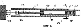
- на Фиг.7 и 8 показаны два этапа демонтажа привода согласно изобретению.- Fig.7 and 8 show two stages of dismantling the drive according to the invention.
На Фиг.1 показан привод согласно изобретению, который содержит электрический двигатель 1, устанавливаемый на неподвижном элементе гондолы двигателя летательного аппарата, например, на передней панели реверсора тяги решетчатого типа (известной из других источников).Figure 1 shows the drive according to the invention, which contains an
Передняя панель такой конструкции обозначена на Фиг.5 и 6 позицией 3.A front panel of this design is indicated in FIGS. 5 and 6 by 3.
Привод согласно изобретению содержит также салазки 5, установленные с возможностью поступательного перемещения внутри направляющей 7, закрепленной на элементе, установленном с возможностью перемещения относительно неподвижного элемента гондолы. Подвижный элемент такого типа может представлять собой, например, подвижный капот 9 реверсора тяги решетчатого типа, как показано на Фиг.5 и 6.The drive according to the invention also comprises a
Внутри салазок 5 установлены элемент, образующий опору 11, и шпонка 13, проходящая как через салазки 5, так и через опору 11 и соединяющая эти элементы.Inside the
Внутри опоры 11 установлен первый шаровой шарнир 15, через который проходит штифт 17.Inside the
На этом шаровом шарнире 15 с тремя степенями свободы и с зазором по отношению к салазкам 5 установлен стакан 19, в котором располагается червячный винт 21, соединенный, в свою очередь, с валом 23 двигателя 1 вторым шаровым шарниром 25, прикрепленным к этому валу 23 посредством штифта 27.A
На ближнем к двигателю 1 конце стакана 19 закреплена гайка 29, взаимодействующая с витками червячного винта 21.At the end of the
Способ действия и преимущества вышеописанного привода заключаются в следующем.The method of action and advantages of the above drive are as follows.
При вращении электрического двигателя 1 приводится во вращение червячный винт 21, благодаря чему гайка 29, а вместе с ней стакан 19 и салазки 5 приводятся в поступательное движение внутри направляющей 7.When the
Благодаря тому, что первый шаровой шарнир 15 удален от двигателя 1 на расстояние, по меньшей мере равное длине червячного винта 21, удается минимизировать угол между осью червячного винта 21 и направлением перемещения салазок 5, когда эти салазки смещаются относительно оси двигателя.Due to the fact that the
Наличие двух шаровых шарниров 15 и 25 в передаточной цепочке между двигателем 1 и салазками 5 повышает гибкость этой передаточной цепочки в отношении отклонений салазок относительно оси, задаваемой двигателем.The presence of two
Следует отметить, что установка гайки 29 в стакан 19, который, в свою очередь, установлен внутри салазок 5 с помощью шпонки посредством опоры 11, представляет собой изящное решение установки указанной гайки на указанных салазках.It should be noted that the installation of the
Способ сборки привода согласно изобретению более наглядно проиллюстрирован на Фиг.2-4.A method of assembling a drive according to the invention is more clearly illustrated in FIGS. 2-4.
Как видно из Фиг.2, в первую очередь устанавливают стакан 19 с гайкой 29 на опору 11 посредством первого шарового шарнира 15 (Фиг.2).As can be seen from Figure 2, first set the
Затем собранный таким образом узел помещают внутрь салазок 5, и в салазки 5 и опору 11 вводят шпонку 13, фиксируя таким образом эти два элемента относительно друг друга (Фиг.3).Then, the assembly thus assembled is placed inside the
Затем внутрь гайки 29 помещают червячный винт 21 с шаровым шарниром 25 (Фиг.4).Then, a
Наконец, собранный таким образом узел закрепляют на валу 23 электрического двигателя 1 с помощью штифта 27, проходящего через шаровой шарнир 25 (см. Фиг.1).Finally, the assembly thus assembled is secured to the
Как ясно из вышеизложенного, различные элементы привода согласно изобретению могут быть очень просто соединены с использованием шпонок и штифтов.As is clear from the foregoing, the various drive elements according to the invention can be very simply connected using keys and pins.
На Фиг.5 и 6 показано, как привод описанного типа может быть установлен на реверсоре тяги решетчатого типа, который содержит, как было указано, с одной стороны, неподвижный элемент 3, содержащий переднюю панель, и, с другой стороны, по меньшей мере один подвижный элемент 9, содержащий подвижный капот.Figures 5 and 6 show how a drive of the type described can be mounted on a trellis type thrust reverser, which comprises, as indicated, on the one hand, a
В этом примере направляющие 7 закреплены на передней панели 3.In this example, the
После монтажа салазок 5 со стаканом 19 (не показан) и червячным винтом 21 на подвижном капоте 9 этот капот 9 располагают на передней панели 3 так, что салазки 5 входят в направляющую 7.After mounting the
Затем подвижный капот 9 сдвигают вперед, то есть в направлении стрелки F1 на Фиг.5.Then, the
Это поступательное перемещение продолжается, пока конец червячного винта 21 не пройдет через элемент 31 передней панели 3.This translational movement continues until the end of the
Затем этот конец винта 21 соединяют с электрическим двигателем 1, как показано стрелкой F2 на Фиг.6.Then this end of the
Следует отметить, что при использовании привода согласно изобретению отсутствует необходимость в специальной регулировке сопряжения электрического двигателя 1 и приводной гайки 29, потому что по самой своей природе червячный винт 21 не имеет предопределенного углового положения, а потому автоматически занимает положение, соответствующее угловому расположению гайки.It should be noted that when using the drive according to the invention, there is no need for special adjustment of the interface between the
Если червячный винт 21 заклинит внутри гайки 29, что может вызвать заклинивание капота 9 относительно передней панели 3, то для решения этой проблемы достаточно будет вынуть штифт 27, соединяющий червячный винт 21 с электрическим двигателем 1, как показано стрелкой F3 на Фиг.7, что позволит легко сдвинуть капот 9 по направлению течения воздуха, то есть в направлении стрелки F4 на Фиг.8. Это позволит отделить салазки 5 от направляющей 7 и, например, выполнить необходимые технические работы или заменить стакан 1, и/или червячный винт, и/или гайку 29.If the
Как видно из вышеизложенного, привод согласно изобретению очень прост в обслуживании.As can be seen from the foregoing, the drive according to the invention is very easy to maintain.
Разумеется, настоящее изобретение ни в коей мере не ограничено описанными и проиллюстрированными вариантами осуществления, которые приводятся здесь исключительно в качестве примеров.Of course, the present invention is in no way limited to the described and illustrated embodiments, which are given solely as examples.
При этом следует иметь в виду, что термин «шаровой шарнир», используемый в данном патентном документе, охватывает любые соединительные приспособления, эквивалентные механическому шаровому шарниру, то есть любые соединительные приспособления, обеспечивающие две степени свободы вращения.It should be borne in mind that the term "ball joint" as used in this patent document covers any connectors that are equivalent to a mechanical ball joint, that is, any connectors that provide two degrees of freedom of rotation.
Такие соединительные приспособления могут включать, в частности, карданные шарниры или же упругие муфты, например, типа «Paulstra».Such couplings may include, in particular, cardan joints or flexible couplings, for example of the Paulstra type.
Claims (9)
Applications Claiming Priority (3)
| Application Number | Priority Date | Filing Date | Title |
|---|---|---|---|
| FR0707048A FR2921976B1 (en) | 2007-10-08 | 2007-10-08 | ACTUATOR FOR MOBILE STRUCTURE OF AN AIRCRAFT NACELLE, AND NACELLE COMPRISING AT LEAST ONE ACTUATOR |
| FR0707048 | 2007-10-08 | ||
| PCT/FR2008/001279 WO2009090319A1 (en) | 2007-10-08 | 2008-09-12 | Actuator for an aircraft nacelle mobile structure, and nacelle comprising at least one such actuator |
Publications (2)
| Publication Number | Publication Date |
|---|---|
| RU2010117754A RU2010117754A (en) | 2011-11-20 |
| RU2471083C2 true RU2471083C2 (en) | 2012-12-27 |
Family
ID=39540711
Family Applications (1)
| Application Number | Title | Priority Date | Filing Date |
|---|---|---|---|
| RU2010117754/06A RU2471083C2 (en) | 2007-10-08 | 2008-09-12 | Drive for movable element of aircraft nacelle, and nacelle containing such drive |
Country Status (10)
| Country | Link |
|---|---|
| US (1) | US8464512B2 (en) |
| EP (1) | EP2198143B1 (en) |
| CN (1) | CN101809273B (en) |
| AT (1) | ATE509198T1 (en) |
| BR (1) | BRPI0818495A2 (en) |
| CA (1) | CA2700184C (en) |
| ES (1) | ES2365297T3 (en) |
| FR (1) | FR2921976B1 (en) |
| RU (1) | RU2471083C2 (en) |
| WO (1) | WO2009090319A1 (en) |
Families Citing this family (18)
| Publication number | Priority date | Publication date | Assignee | Title |
|---|---|---|---|---|
| US9759087B2 (en) | 2007-08-08 | 2017-09-12 | Rohr, Inc. | Translating variable area fan nozzle providing an upstream bypass flow exit |
| WO2009029401A2 (en) | 2007-08-08 | 2009-03-05 | Rohr, Inc. | Variable area fan nozzle with bypass flow |
| EP2278146B1 (en) * | 2009-06-16 | 2013-07-24 | Rohr, Inc. | Actuation system for a translating variable area fan nozzle |
| US8875486B2 (en) | 2010-05-17 | 2014-11-04 | Rohr, Inc. | Guide system for nacelle assembly |
| FR2960600B1 (en) * | 2010-06-01 | 2013-10-25 | Aircelle Sa | ACTUATING SYSTEM OF A PUSH REVERSING DEVICE |
| US8511973B2 (en) | 2010-06-23 | 2013-08-20 | Rohr, Inc. | Guide system for nacelle assembly |
| US8720183B2 (en) * | 2011-03-02 | 2014-05-13 | Spirit Aerosystems, Inc. | Thrust reverser translating sleeve assembly |
| FR2974150B1 (en) * | 2011-04-14 | 2013-04-12 | Aircelle Sa | THRUST INVERTER FOR AIRCRAFT TURBOREACTOR |
| US8615982B2 (en) * | 2011-07-05 | 2013-12-31 | Hamilton Sundstrand Corporation | Integrated electric variable area fan nozzle thrust reversal actuation system |
| US9114581B2 (en) | 2011-12-22 | 2015-08-25 | The Goodyear Tire & Rubber Company | Method of applying ply to a tire building drum |
| US8800629B2 (en) * | 2011-12-22 | 2014-08-12 | The Goodyear Tire & Rubber Company | Tire ply applier |
| FR3002593B1 (en) * | 2013-02-25 | 2015-03-27 | Aircelle Sa | ACTUATOR FOR AIRCRAFT TURBO BOREHOLE NACELLE |
| FR3019523B1 (en) * | 2014-04-08 | 2018-02-02 | Safran Landing Systems | METHOD FOR OPERATING AIRCRAFT SAIL TRAPPERS, AND ACTUATOR APPLYING THE SAME |
| EP3143306B1 (en) * | 2014-05-16 | 2021-06-23 | Bombardier Inc. | Actuators and methods for aircraft flight control surfaces |
| FR3028295B1 (en) * | 2014-11-06 | 2020-01-17 | Safran Electronics & Defense | SYSTEM FOR ACTUATING A MOBILE STRUCTURE OF A DRIVE INVERTER OF AN AIRCRAFT, DRIVE INVERTER AND REACTOR COMPRISING SUCH A SYSTEM. |
| DE102015206985A1 (en) | 2015-04-17 | 2016-10-20 | Rolls-Royce Deutschland Ltd & Co Kg | Engine cowling of an aircraft gas turbine |
| US9976696B2 (en) | 2016-06-21 | 2018-05-22 | Rohr, Inc. | Linear actuator with multi-degree of freedom mounting structure |
| US10612491B2 (en) * | 2017-09-25 | 2020-04-07 | Rohr, Inc. | Mounting device with pin actuator |
Citations (6)
| Publication number | Priority date | Publication date | Assignee | Title |
|---|---|---|---|---|
| GB1386232A (en) * | 1971-03-31 | 1975-03-05 | Short Brothers & Harland Ltd | Fluid propulsion systems |
| US4005822A (en) * | 1975-12-22 | 1977-02-01 | Rohr Industries, Inc. | Fan duct thrust reverser |
| EP0109291A1 (en) * | 1982-11-12 | 1984-05-23 | Fuji Photo Film Co., Ltd. | Photopolymerizable composition |
| EP0884470A1 (en) * | 1997-06-12 | 1998-12-16 | Hispano-Suiza Aérostructures | Thrust reverser for a turbofan with variable outlet area |
| RU2142569C1 (en) * | 1996-11-14 | 1999-12-10 | Испано Сюиза | Electrical control system for turbojet engine thrust reverser |
| EP1239139A1 (en) * | 2001-03-08 | 2002-09-11 | Hurel-Hispano Le Havre | Thrust reverser actuating system in a turbojet engine |
Family Cites Families (7)
| Publication number | Priority date | Publication date | Assignee | Title |
|---|---|---|---|---|
| US4216909A (en) * | 1977-10-04 | 1980-08-12 | Rolls-Royce Limited | Brake mechanism for rotary parts |
| FR2605054B1 (en) * | 1986-10-08 | 1990-07-27 | Snecma | POSITION SENSING RAMP BEARING ASSEMBLY FOR A TURBOSOUFFLANTE PUSH INVERTER |
| GB2198999B (en) * | 1986-12-17 | 1990-08-29 | Rolls Royce Plc | Fluid propulsion engine with flow exit control device |
| FR2651278B1 (en) * | 1989-08-23 | 1994-05-06 | Hispano Suiza | INVERTER WITH GRIDS WITHOUT SLIDING COVER FOR TURBOREACTOR. |
| FR2669679B1 (en) * | 1990-11-28 | 1994-04-29 | Sud Ouest Conception Aeronauti | GAS EJECTION NOZZLE FOR A REACTION ENGINE AND A REACTION ENGINE EQUIPPED WITH SUCH A NOZZLE, PARTICULARLY A SEPARATE FLOW TYPE ENGINE. |
| FR2758161B1 (en) * | 1997-01-09 | 1999-02-05 | Hispano Suiza Sa | GRID DRIVE INVERTER WITH OPTIMIZED CONTROL JACK INSTALLATION |
| US6170254B1 (en) * | 1998-12-18 | 2001-01-09 | Rohr, Inc. | Translating sleeve for cascade type thrust reversing system for fan gas turbine engine for an aircraft |
-
2007
- 2007-10-08 FR FR0707048A patent/FR2921976B1/en not_active Expired - Fee Related
-
2008
- 2008-09-12 WO PCT/FR2008/001279 patent/WO2009090319A1/en active Application Filing
- 2008-09-12 AT AT08871116T patent/ATE509198T1/en not_active IP Right Cessation
- 2008-09-12 BR BRPI0818495A patent/BRPI0818495A2/en not_active IP Right Cessation
- 2008-09-12 ES ES08871116T patent/ES2365297T3/en active Active
- 2008-09-12 US US12/682,139 patent/US8464512B2/en not_active Expired - Fee Related
- 2008-09-12 CN CN2008801094028A patent/CN101809273B/en not_active Expired - Fee Related
- 2008-09-12 RU RU2010117754/06A patent/RU2471083C2/en not_active IP Right Cessation
- 2008-09-12 EP EP08871116A patent/EP2198143B1/en not_active Not-in-force
- 2008-09-12 CA CA2700184A patent/CA2700184C/en not_active Expired - Fee Related
Patent Citations (6)
| Publication number | Priority date | Publication date | Assignee | Title |
|---|---|---|---|---|
| GB1386232A (en) * | 1971-03-31 | 1975-03-05 | Short Brothers & Harland Ltd | Fluid propulsion systems |
| US4005822A (en) * | 1975-12-22 | 1977-02-01 | Rohr Industries, Inc. | Fan duct thrust reverser |
| EP0109291A1 (en) * | 1982-11-12 | 1984-05-23 | Fuji Photo Film Co., Ltd. | Photopolymerizable composition |
| RU2142569C1 (en) * | 1996-11-14 | 1999-12-10 | Испано Сюиза | Electrical control system for turbojet engine thrust reverser |
| EP0884470A1 (en) * | 1997-06-12 | 1998-12-16 | Hispano-Suiza Aérostructures | Thrust reverser for a turbofan with variable outlet area |
| EP1239139A1 (en) * | 2001-03-08 | 2002-09-11 | Hurel-Hispano Le Havre | Thrust reverser actuating system in a turbojet engine |
Also Published As
| Publication number | Publication date |
|---|---|
| RU2010117754A (en) | 2011-11-20 |
| BRPI0818495A2 (en) | 2015-09-29 |
| CA2700184C (en) | 2016-04-19 |
| CA2700184A1 (en) | 2009-07-23 |
| WO2009090319A1 (en) | 2009-07-23 |
| ATE509198T1 (en) | 2011-05-15 |
| CN101809273B (en) | 2013-05-01 |
| EP2198143A1 (en) | 2010-06-23 |
| US20100218480A1 (en) | 2010-09-02 |
| ES2365297T3 (en) | 2011-09-28 |
| EP2198143B1 (en) | 2011-05-11 |
| FR2921976A1 (en) | 2009-04-10 |
| US8464512B2 (en) | 2013-06-18 |
| FR2921976B1 (en) | 2009-12-04 |
| CN101809273A (en) | 2010-08-18 |
Similar Documents
| Publication | Publication Date | Title |
|---|---|---|
| RU2471083C2 (en) | Drive for movable element of aircraft nacelle, and nacelle containing such drive | |
| US11434850B2 (en) | Split sleeve hidden door thrust reverser | |
| US8740137B2 (en) | Removable air intake structure for a turbofan engine nacelle | |
| RU2538142C2 (en) | Thrust reverser | |
| US7992589B2 (en) | Dual butterfly valve driven by a common drive motor | |
| KR102119689B1 (en) | Coupling rod | |
| CN111344480B (en) | Thrust reverser with movable cascades for an aircraft propulsion unit and associated mounting and dismounting method | |
| RU2012124297A (en) | ROTARY REVERSE | |
| WO2013015985A1 (en) | Actuating force transmitting device of an exhaust-gas turbocharger | |
| CN103635681B (en) | Driving assembly for the trhrust-reversal device of aircraft engine | |
| RU2009111050A (en) | LOCKING SYSTEM FOR THE FLEXIBLE COVER OF THE GONDOLA | |
| US20070031242A1 (en) | Movement system for the inspection of a turbine | |
| US10669971B2 (en) | Thrust reverser for a turbojet engine nacelle, comprising cascades partially integrated in the cowls | |
| US7318577B2 (en) | Motor-operated valve assembly | |
| JPS5930937B2 (en) | Branch transmission device for installation on ship drive equipment | |
| CN101273196B (en) | Starter motor | |
| US20140161592A1 (en) | Guidance of turbine engine shafts | |
| FR3085726A1 (en) | PUSH INVERTER WITH MOBILE C-STRUCTURE FOR A POWERED AIRCRAFT ASSEMBLY, AND MAINTENANCE METHOD RELATING THERETO | |
| EA012690B1 (en) | Actuator device | |
| RU2007130231A (en) | METHOD FOR FASTENING A FLEXIBLE TRANSMISSION SHAFT IN A REVERSE REACTOR AND THE RELATED REVERSE REACTOR | |
| CN101956609B (en) | Actuating mechanism for electron speed regulator | |
| CN117917499A (en) | Opening/closing body driving device | |
| US8992193B2 (en) | Shaft assembly including a contained shaft spring load | |
| CN216803170U (en) | Centering device | |
| KR920006225B1 (en) | Engine starter motor with a planetary speed reduction gear |
Legal Events
| Date | Code | Title | Description |
|---|---|---|---|
| MM4A | The patent is invalid due to non-payment of fees |
Effective date: 20150913 |