RU2470496C2 - System and method of control over illuminators - Google Patents
System and method of control over illuminators Download PDFInfo
- Publication number
- RU2470496C2 RU2470496C2 RU2009126539/07A RU2009126539A RU2470496C2 RU 2470496 C2 RU2470496 C2 RU 2470496C2 RU 2009126539/07 A RU2009126539/07 A RU 2009126539/07A RU 2009126539 A RU2009126539 A RU 2009126539A RU 2470496 C2 RU2470496 C2 RU 2470496C2
- Authority
- RU
- Russia
- Prior art keywords
- data
- color
- predetermined
- sensors
- light
- Prior art date
Links
Images


Classifications
-
- H—ELECTRICITY
- H05—ELECTRIC TECHNIQUES NOT OTHERWISE PROVIDED FOR
- H05B—ELECTRIC HEATING; ELECTRIC LIGHT SOURCES NOT OTHERWISE PROVIDED FOR; CIRCUIT ARRANGEMENTS FOR ELECTRIC LIGHT SOURCES, IN GENERAL
- H05B45/00—Circuit arrangements for operating light-emitting diodes [LED]
- H05B45/20—Controlling the colour of the light
- H05B45/22—Controlling the colour of the light using optical feedback
-
- H—ELECTRICITY
- H05—ELECTRIC TECHNIQUES NOT OTHERWISE PROVIDED FOR
- H05B—ELECTRIC HEATING; ELECTRIC LIGHT SOURCES NOT OTHERWISE PROVIDED FOR; CIRCUIT ARRANGEMENTS FOR ELECTRIC LIGHT SOURCES, IN GENERAL
- H05B45/00—Circuit arrangements for operating light-emitting diodes [LED]
- H05B45/20—Controlling the colour of the light
- H05B45/28—Controlling the colour of the light using temperature feedback
Landscapes
- Circuit Arrangement For Electric Light Sources In General (AREA)
- Electroluminescent Light Sources (AREA)
Abstract
Description
Область техникиTechnical field
Настоящее изобретение относится к области освещения и, в частности, управлению цветом и интенсивностью, излучаемого источником света.The present invention relates to the field of lighting and, in particular, to control the color and intensity emitted by a light source.
Уровень техникиState of the art
Достижения в развитии и усовершенствовании светового потока светоизлучающих устройств, например твердотельных полупроводниковых и органических светодиодов (СИД), сделали эти устройства пригодными для использования в применениях общего освещения, включающих в себя архитектурное, увеселительное и дорожное освещение. Светодиоды составляют все большую конкуренцию таким источникам света, как лампы накаливания, люминесцентные лампы и газоразрядные лампы высокой интенсивности.Advances in the development and improvement of the luminous flux of light-emitting devices, such as solid state semiconductor and organic light emitting diodes (LEDs), have made these devices suitable for use in general lighting applications, including architectural, entertainment and road lighting. LEDs are increasingly competing with light sources such as incandescent lamps, fluorescent lamps and high-intensity discharge lamps.
Одна из задач в связи с твердотельным освещением состоит в разработке системы и/или способа, которые могут устанавливать и поддерживать интенсивность и цветность смешанного света, излучаемого множеством цветных, например, синих и желтых или красных, зеленых и синих СИД. Это может быть проблемой, поскольку свет, излучаемый СИД, может изменяться в зависимости от условий эксплуатации, отличных от электрических токов, обеспечиваемых на СИД. Традиционно, системы, которые могут исправлять эту зависимость, используют оптическую обратную связь на основании сигналов, обеспечиваемых одним или более оптическими датчиками. Датчики могут воспринимать часть излучаемого света, и их можно использовать для определения цветности и интенсивности воспринимаемого света. В свою очередь, информация о цветности и интенсивности можно, соответственно, использовать для регулировки токов возбуждения СИД. Однако для возможности эффективного управления с обратной связью нужно устранить ряд эффектов. Например, во-первых, спектральная чувствительность известных недорогих цветовых датчиков RGB, в практических целях, недостаточно точно повторяет спектральную чувствительность человеческого глаза. Во-вторых, спектральные распределения мощности (SPD) СИД могут изменяться с рабочей температурой СИД.One of the challenges associated with solid state lighting is to develop a system and / or method that can set and maintain the intensity and color of the mixed light emitted from a variety of color, for example, blue and yellow or red, green and blue LEDs. This can be a problem since the light emitted by the LEDs may vary depending on operating conditions other than the electric currents provided on the LEDs. Traditionally, systems that can correct this relationship utilize optical feedback based on signals provided by one or more optical sensors. Sensors can sense part of the emitted light, and they can be used to determine the color and intensity of the perceived light. In turn, information about the color and intensity can, respectively, be used to adjust the excitation currents of the LEDs. However, to be able to effectively manage feedback, a number of effects need to be eliminated. For example, firstly, the spectral sensitivity of the well-known inexpensive RGB color sensors, for practical purposes, does not accurately repeat the spectral sensitivity of the human eye. Secondly, the spectral power distribution (SPD) of an LED can vary with the operating temperature of the LED.
Например, на фиг.1 показана нормализованная спектральная чувствительность стандартного наблюдателя-человека, представленная функциями согласования цветов CIE ![]()
![]()
В технике общеизвестно, что SPD, описанную посредством ![]()
![]()
![]()
![]()
![]()
![]()
иand
![]()
![]()
Следовательно, трехцветные значения, определенные на основании сигналов, обеспечиваемых цветовыми датчиками RGB с недостаточно точными чувствительностями, могут не обеспечивать практически полезные указания трехцветных значений CIE. Общеизвестно, что другие функции согласования цветов можно использовать для определения соответствующих основных цветов в соответствующем цветовом пространстве.Therefore, tricolor values determined based on signals provided by RGB color sensors with insufficiently accurate sensitivities may not provide practically useful indications of tricolor CIE values. It is well known that other color matching functions can be used to determine the corresponding primary colors in the corresponding color space.
Известные решения, например, представленные в патенте США № 6,507,159, раскрывают способ и систему для управления осветительным прибором на основе RGB СИД, которые позволяют отслеживать трехцветные значения опорного сигнала и сигнала обратной связи определенным образом. Прямые токи, возбуждающие осветительный прибор на основе СИД, регулируются на основании сравнения между трехцветными значениями сигнала обратной связи и опорными трехцветными значениями до тех пор, пока сравнение не перестанет показывать разность между ними. Трехцветные значения определяются с использованием определенной комбинации фильтров и датчиков. Однако согласование фильтров и датчиков для точного воспроизведения функций согласования цветов CIE, даже в лабораторных условиях управляемой температуры, представляет собой сложную задачу. Поэтому полезные комбинации фильтров и датчиков могут быть дорогими, что обсуждается в работе G. P. Eppeldauer, "A Reference Tristimulus Colorimeter," Proceedings of the Ninth Congress of the International Color Association of the Optical Engineering Society, SPIE 4421, стр. 749-752, (2002), Bellingham, WA, USA. Кроме того, управление с обратной связью, основанное только на трехцветных значениях CIE, не позволяет отделить цветность (т.е. цвет) от интенсивности и поэтому может оказаться неэффективным при подавлении ряда нежелательных флуктуаций цветности.Known solutions, for example, presented in US patent No. 6,507,159, disclose a method and system for controlling a lighting fixture based on RGB LEDs, which allow you to track the three-color values of the reference signal and the feedback signal in a certain way. The forward currents driving the LED-based illuminator are controlled based on a comparison between the three-color values of the feedback signal and the reference three-color values until the comparison no longer shows the difference between them. Tri-color values are determined using a specific combination of filters and sensors. However, matching filters and sensors to accurately reproduce CIE color matching functions, even under laboratory controlled temperature conditions, is a daunting task. Therefore, useful combinations of filters and sensors can be expensive, as discussed in GP Eppeldauer, "A Reference Tristimulus Colorimeter," Proceedings of the Ninth Congress of the International Color Association of the Optical Engineering Society, SPIE 4421, pp. 749-752, ( 2002), Bellingham, WA, USA. In addition, feedback control based only on tri-color CIE values does not allow separation of color (i.e. color) from intensity and therefore may be ineffective in suppressing a number of undesirable color fluctuations.
В работе B. T. Barnes "A Four-Filter Photoelectric Colorimeter," Journal of the Optical Society of America 29, (10), стр. 448-452, (1939) описано, как разложить функцию согласования цветов ![]()
![]()
![]()
![]()
![]()
![]()
![]()
![]()
![]()
![]()
где l и s обозначают диапазон длинных и коротких волн, соответственно. Для приборов, качество которых ниже лабораторного, в уровне техники нередко используются надлежащим образом масштабированные версии пары синий фильтр/детектор для представления спектральных чувствительностей и ![]()
![]()
![]()
![]()
В работе B. A. Wandell и J. E. Farrell "Water into Wine: Converting Scanner RGB to Tristimulus XYZ" Device-Independent Color Imaging and Imaging Systems Integration, Proc. SPIE 1909, стр. 92-101, (1993) описано, как преобразовывать данные датчиков RGB в трехцветные значения XYZ с использованием матрицы преобразования, которую можно заранее определить методом наименьших квадратов на этапе калибровки. На этапе калибровки используются данные от идеальных датчиков согласования цветов CIE, и калибровочные данные от неидеальных датчиков RGB получаются путем измерений набора SPD для каждого датчика. Однако Wandell не предлагает использовать метод наименьших квадратов для аппаратов с обратной связью в реальном времени, а также применять его для управления источником света. Преобразование также применяется к измеренным данным цветовых датчиков RGB для каждого пикселя изображения.In B. A. Wandell and J. E. Farrell "Water into Wine: Converting Scanner RGB to Tristimulus XYZ" Device-Independent Color Imaging and Imaging Systems Integration, Proc. SPIE 1909, pp. 92-101, (1993) describes how to convert RGB sensor data to tri-color XYZ values using a transform matrix that can be predefined by the least squares method at the calibration stage. The calibration phase uses data from ideal CIE color matching sensors, and calibration data from non-ideal RGB sensors is obtained by measuring the SPD set for each sensor. However, Wandell does not suggest using the least squares method for real-time feedback devices, or using it to control a light source. The conversion also applies to the measured RGB color sensor data for each pixel in the image.
В работе G. D. Finlayson и M. S. Drew "Constrained Least-Squares Regression in Color Spaces," Journal of Electronic Imaging 6, (4), стр. 484-493, (1997) описан способ, аналогичный решению, предложенному в вышеупомянутой работе Wandell и др., который страдает теми же ограничениями.GD Finlayson and MS Drew "Constrained Least-Squares Regression in Color Spaces," Journal of
На фиг.2 показан пример SPD света, излучаемого модулем RGB СИД при двух разных рабочих температурах, но в остальном в одинаковых стационарных условиях эксплуатации. Температура окружающей среды один раз составляла 25°C, а в другой раз 70°C. Помимо эффектов разной рабочей температуры различие в токах возбуждения СИД в СИД разных цветов может приводить к различию в скоростях рассеяния мощности и, следовательно, к различию в температуре перехода СИД. Это различие может проявляться при сравнении SPD в различных сдвигах пиковой длины волны и различном расширении SPD и, следовательно, может быть причиной нелинейного изменения цветности смешанного света в зависимости от токов возбуждения и рабочих температур каждого СИД. Кроме того, теплообмен между СИД разных цветов может приводить к возникновению взаимозависимостей между температурами перехода СИД. Следовательно, общеизвестные законы аддитивности цветов Грассмана не могут обеспечить точные описания цвета смешанного света без учета эффектов самонагрева и взаимного нагрева СИД и любых оптических датчиков, применяемых для измерения генерируемого света.Figure 2 shows an example of an SPD of light emitted from an RGB LED module at two different operating temperatures, but otherwise under the same stationary operating conditions. The ambient temperature was once 25 ° C, and another time 70 ° C. In addition to the effects of different operating temperatures, differences in LED drive currents in LEDs of different colors can lead to differences in power dissipation rates and, consequently, to differences in LED transition temperatures. This difference can occur when comparing SPDs at different shifts of the peak wavelength and different expansion of the SPD and, therefore, can cause a nonlinear change in the color of the mixed light depending on the excitation currents and operating temperatures of each LED. In addition, heat transfer between LEDs of different colors can lead to interdependencies between the transition temperatures of the LEDs. Therefore, the well-known Grassmann color additivity laws cannot provide accurate descriptions of the color of mixed light without taking into account the effects of self-heating and mutual heating of LEDs and any optical sensors used to measure the generated light.
Таким образом, на работе систем управления осветительными приборами с обратной связью могут негативно сказываться некоторые эффекты, в том числе тот, что датчики RGB с разными чувствительностями будут обеспечивать разные уникальные отклики на свет с одним и тем же SPD. Изменения в SPD цветного СИД, как описано выше, также будут приводить к изменениям в откликах датчиков RGB. Поэтому изменения сигналов датчиков RGB в ответ на изменения SPD также будут уникальными. Кроме того, датчики RGB, которые приближены к идеальным датчикам, будут, в ответ на одно и то же SPD, обеспечивать различные сигналы по сравнению с идеальными датчиками. Кроме того, чувствительность датчика RGB также может изменяться с его температурой.Thus, some effects may negatively affect the operation of control systems for lighting fixtures with feedback, including the fact that RGB sensors with different sensitivities will provide different unique light responses with the same SPD. Changes to the SPD of the color LED, as described above, will also lead to changes in the responses of the RGB sensors. Therefore, changes in RGB sensor signals in response to SPD changes will also be unique. In addition, RGB sensors that are close to ideal sensors will, in response to the same SPD, provide different signals compared to ideal sensors. In addition, the sensitivity of the RGB sensor can also vary with its temperature.
Поэтому существует необходимость в системе и способе управления осветительными приборами, которые позволяют эффективно управлять светом, генерируемым осветительным прибором.Therefore, there is a need for a system and method for controlling lighting devices that can effectively control the light generated by the lighting device.
Эта информация об уровне техники призвана раскрыть информацию, которую заявитель, предположительно, считает имеющей отношение к настоящему изобретению. Не следует делать никаких предположений и не следует толковать в том смысле, что какая-либо часть вышеприведенной информации составляет предпосылки настоящего изобретения.This prior art information is intended to disclose information that the applicant is deemed to consider relevant to the present invention. No assumptions should be made and should not be interpreted in the sense that any part of the above information constitutes the premises of the present invention.
Сущность изобретенияSUMMARY OF THE INVENTION
Задачей настоящего изобретения является обеспечение системы и способа управления осветительными приборами. Согласно аспекту настоящего изобретения предусмотрен способ для управления одним или более светоизлучающими элементами (СИЭ), возбуждаемыми прямыми токами, для генерации смешанного света. Способ содержит этапы сбора данных датчиков, представляющие смешанный свет; обеспечения данных контрольной точки, представляющие требуемый смешанный свет; преобразования данных датчиков в первые данные, выраженные в координатах заранее определенной системы цветовых координат; преобразования данных контрольной точки во вторые данные, выраженные в координатах упомянутой заранее определенной системы цветовых координат; сравнения первых и вторых данных и определения разности между первыми и вторыми данными; регулирования упомянутых прямых токов в ответ на разность между первыми и вторыми данными, для того чтобы уменьшить разность между упомянутыми первыми данными и вторыми данными.An object of the present invention is to provide a system and method for controlling lighting devices. According to an aspect of the present invention, there is provided a method for controlling one or more light emitting elements (SEEs) driven by direct currents to generate mixed light. The method comprises the steps of collecting sensor data representing mixed light; providing control point data representing the desired mixed light; converting the sensor data into first data expressed in the coordinates of a predetermined color coordinate system; converting the control point data into second data expressed in the coordinates of said predetermined color coordinate system; comparing the first and second data and determining the difference between the first and second data; regulating said forward currents in response to a difference between the first and second data in order to reduce the difference between said first data and second data.
Согласно другому аспекту настоящего изобретения предусмотрена система для управления одним или более светоизлучающими элементами (СИЭ), возбуждаемыми прямыми токами, для генерации смешанного света. Система содержит один или более оптических датчиков для сбора данных датчиков, представляющих смешанный свет; пользовательский интерфейс для обеспечения данных контрольной точки, представляющих требуемый смешанный свет; контроллер, причем контроллер преобразует данные датчиков в первые данные, выраженные в координатах заранее определенной системы цветовых координат, причем контроллер дополнительно преобразует данные контрольной точки во вторые данные, выраженные в координатах заранее определенной системы цветовых координат, причем контроллер дополнительно сравнивает первые и вторые данные и определяет разность между первыми и вторыми данными, причем контроллер дополнительно регулирует упомянутые прямые токи в ответ на разность между первыми и вторыми данными; при этом контроллер выполнен с возможностью уменьшать разность между упомянутыми первыми данными и упомянутыми вторыми данными, пока абсолютное значение упомянутой разности не упадет ниже заранее определенного порога.According to another aspect of the present invention, there is provided a system for controlling one or more light emitting elements (SEEs) driven by direct currents to generate mixed light. The system comprises one or more optical sensors for collecting sensor data representing mixed light; a user interface for providing control point data representing the desired mixed light; a controller, the controller converting the sensor data into first data expressed in the coordinates of a predetermined color coordinate system, the controller further converting the control point data into second data expressed in the coordinates of a predetermined color coordinate system, the controller further comparing the first and second data and determines the difference between the first and second data, and the controller further adjusts said forward currents in response to the difference between the first and volts rymi data; wherein the controller is configured to reduce the difference between said first data and said second data until the absolute value of said difference falls below a predetermined threshold.
Краткое описание чертежейBrief Description of the Drawings
Фиг.1 показывает нормализованную спектральную чувствительность стандартного наблюдателя-человека, представленная функциями согласования цветов CIE ![]()
![]()
Фиг.2 показывает пример двух SPD для модуля RGB СИД, эксплуатируемого при температуре окружающей среды 25°C и 70°C.Figure 2 shows an example of two SPDs for an RGB LED module operating at an ambient temperature of 25 ° C and 70 ° C.
Фиг.3 показывает архитектуру системы обратной связи и управления для осветительного прибора на основе СИЭ согласно варианту осуществления настоящего изобретения.Figure 3 shows the architecture of a feedback and control system for an EIE-based lighting device according to an embodiment of the present invention.
Фиг.4 показывает пример рекурсивного треугольного разбиения цветового пространства RGB согласно варианту осуществления настоящего изобретения.4 shows an example of a recursive triangular partition of an RGB color space according to an embodiment of the present invention.
Фиг.5 показывает блок-схему иллюстративного способа компенсации рабочей температуры СИЭ согласно одному варианту осуществления настоящего изобретения.FIG. 5 shows a flowchart of an illustrative method for compensating an operating temperature of an SEE according to one embodiment of the present invention.
Фиг.6 показывает блок-схему иллюстративного процесса преобразования белого режима согласно одному варианту осуществления настоящего изобретения.6 shows a flowchart of an example white mode conversion process according to one embodiment of the present invention.
Фиг.7 показывает блок-схему иллюстративного процесса отображения цветовой гаммы для преобразования режима цветности согласно одному варианту осуществления настоящего изобретения.7 shows a flowchart of an illustrative color gamut display process for converting a color mode according to one embodiment of the present invention.
Фиг.8 показывает блок-схему иллюстративного способа общего преобразования согласно одному варианту осуществления настоящего изобретения.FIG. 8 shows a flowchart of an illustrative general conversion method according to one embodiment of the present invention.
Фиг.9 показывает схему системы обратной связи и управления, в которой используется ПИ схема управления согласно одному варианту осуществления настоящего изобретения.FIG. 9 shows a diagram of a feedback and control system in which a PI control circuit is used according to one embodiment of the present invention.
Подробное описание изобретенияDETAILED DESCRIPTION OF THE INVENTION
ОпределенияDefinitions
Термин "светоизлучающий элемент" (СИЭ) используется для определения устройства, которое испускает излучение в диапазоне или комбинации диапазонов электромагнитного спектра, например в видимом диапазоне, инфракрасном и/или ультрафиолетовом диапазоне, будучи активированным, например, за счет подачи на него разности потенциалов или пропускания через него тока. Поэтому светоизлучающий элемент может иметь монохроматическую, квазимонохроматическую, полихроматическую или широкополосную спектральную характеристику излучения. Примерами светоизлучающих элементов служат полупроводниковые, органические или полимерные светодиоды, светодиоды с фосфорным покрытием оптической накачки, нанокристаллические светодиоды с оптической накачкой или другие аналогичные устройства, что хорошо известно специалисту в данной области техники. Кроме того, термин светоизлучающий элемент используется для определения конкретного устройства, которое испускает излучение, например кристалл СИД, и в равной степени может использоваться для определения комбинации конкретного устройства, которое испускает излучение, совместно с корпусом или кожухом, в котором располагается/ются конкретное/ые устройство или устройства.The term "light emitting element" (SEI) is used to define a device that emits radiation in a range or combination of ranges of the electromagnetic spectrum, for example in the visible range, infrared and / or ultraviolet range, being activated, for example, by applying a potential difference or transmission to it through it current. Therefore, the light emitting element may have a monochromatic, quasi-monochromatic, polychromatic or broadband spectral characteristic of the radiation. Examples of light-emitting elements are semiconductor, organic or polymer LEDs, phosphor-coated optical pump LEDs, nanocrystalline optical pump LEDs or other similar devices, which is well known to a person skilled in the art. In addition, the term light-emitting element is used to define a specific device that emits radiation, such as an LED crystal, and can equally be used to define a combination of a specific device that emits radiation, together with the case or casing in which the particular device is located device or devices.
Используемый здесь термин "около" относится к +/-10% отклонению от номинального значения. Следует понимать, что такое отклонение всегда включено в любое данное значение, обеспеченное здесь, независимо от того, имеется ли на него ссылка.As used herein, the term “about” refers to a +/- 10% deviation from the nominal value. It should be understood that such a deviation is always included in any given value provided here, regardless of whether there is a link to it.
Если не указано обратное, все технические и научные термины, используемые здесь, имеют тот же смысл, в котором их обычно понимают специалисты в данной области техники, к которой принадлежит изобретение.Unless otherwise indicated, all technical and scientific terms used herein have the same meaning as is generally understood by those skilled in the art to which the invention belongs.
Настоящее изобретение обеспечивает систему обратной связи и управления для управления электрическими токами, предоставляемыми на один или более СИЭ в осветительном приборе. Система обратной связи и управления может взаимодействовать с оптическими датчиками для восприятия части света, излучаемого СИЭ, пользовательским интерфейсом для обмена информацией с пользователем и системой температурных датчиков. Система температурных датчиков может содержать систему температурных датчиков на основе перехода СИЭ для мониторинга температуры СИЭ и, дополнительно, в необязательном порядке, систему температурных датчиков для мониторинга температуры оптических датчиков.The present invention provides a feedback and control system for controlling electric currents provided to one or more SIEs in a lighting fixture. The feedback and control system can interact with optical sensors to perceive part of the light emitted by the SEE, a user interface for exchanging information with the user and the temperature sensor system. The temperature sensor system may include a temperature sensor system based on the SIE transition for monitoring the temperature of the SIE and, optionally, optionally, a temperature sensor system for monitoring the temperature of the optical sensors.
Согласно настоящему изобретению система обратной связи и управления может быть выполнена так, чтобы определенные сигналы, используемые в ней, коррелировали с цветом или интенсивностью света в координатах выбранного заранее определенного требуемого цветового пространства. Степень корреляции может быть прямо линейно пропорциональной. Эти сигналы могут включать в себя входные и выходные сигналы системы или сигналы, получаемые из них путем преобразования в заранее определенное требуемое цветовое пространство. Эти сигналы могут включать в себя сигналы, указывающие контрольную точку системы. Контрольная точка системы описывает требуемый выход системы и может изменяться пользователем в ходе эксплуатации, инициирующим переход между двумя требуемыми состояниями. Система может быть выполнена с возможностью выполнять переход несколькими, обычно заранее определенными способами.According to the present invention, the feedback and control system can be made so that certain signals used in it correlate with the color or light intensity in the coordinates of the selected predetermined desired color space. The degree of correlation can be directly linearly proportional. These signals can include system input and output signals or signals obtained from them by converting to a predetermined desired color space. These signals may include signals indicating a control point of the system. The control point of the system describes the required system output and can be changed by the user during operation, initiating a transition between the two required states. The system may be configured to perform the transition in several, usually predefined, ways.
Для управления с обратной связью выход и сигнал контрольной точки можно сравнивать в целях определения разности между ними. Разность обычно рассматривается как отклонение выхода от контрольной точки. Каждая разность затем используется для определения изменений соответствующего электрического тока возбуждения для каждой группы СИЭ, что необходимо для уменьшения разности между соответствующим мгновенным и требуемым выходом осветительного прибора. Поэтому информация, закодированная в сигнале контрольной точки или сигнале датчика или в обоих сигналах, должна быть доступна в общем цветовом пространстве до того, как они будут сравнены. Следовательно, может потребоваться преобразование одного или обоих сигналов в выбранное общее цветовое пространство. Согласно настоящему изобретению общее цветовое пространство является рассмотренным выше заранее определенным требуемым цветовым пространством. В общем случае, контроллер выполнен с возможностью регулировать, в ответ на сравнение мгновенного и требуемого выхода, токи возбуждения на светоизлучающие элементы. Согласно варианту осуществления настоящего изобретения токи возбуждения регулируются для уменьшения разности между данными датчиков RGB с обратной связью, которые выражают мгновенный выход, и данными контрольной точки RGB, описывающими требуемый выход, пока абсолютное значение разности не станет меньше заранее определенного порога.For closed loop control, the output and signal of the set point can be compared to determine the difference between them. The difference is usually considered as the deviation of the output from the control point. Each difference is then used to determine the changes in the corresponding electric excitation current for each group of FIE, which is necessary to reduce the difference between the corresponding instantaneous and required output of the lighting device. Therefore, the information encoded in the control point signal or the sensor signal, or in both signals, must be available in the common color space before they are compared. Therefore, it may be necessary to convert one or both of the signals into a selected common color space. According to the present invention, the total color space is the predefined desired color space discussed above. In general, the controller is configured to adjust, in response to comparing the instantaneous and desired output, the excitation currents to the light emitting elements. According to an embodiment of the present invention, the drive currents are adjusted to reduce the difference between the feedback RGB sensor data, which express the instantaneous output, and the RGB control point data describing the desired output, until the absolute difference value is less than a predetermined threshold.
Согласно варианту осуществления настоящего изобретения общее цветовое пространство может задаваться чувствительностью оптических датчиков в некоторых заранее определенных условиях эксплуатации оптических датчиков. В частности, каждая из чувствительностей может использоваться в качестве базисной функции системы координат, которая используется для задания заранее определенного требуемого цветового пространства.According to an embodiment of the present invention, the total color space may be determined by the sensitivity of the optical sensors under certain predetermined operating conditions of the optical sensors. In particular, each of the sensitivities can be used as a basic function of the coordinate system, which is used to specify a predetermined desired color space.
Заметим, что вышеописанный мгновенный выход относится к выходу в моменты, когда свет, излучаемый СИЭ осветительного прибора, взаимодействует с соответствующим датчиком. Мгновенный выход обычно обрабатывается позже, и задержка зависит от характера системы обратной связи. Как известно, мгновенное значение сигнала обратной связи в моменты времени, когда он фактически обрабатывается, обычно соответствует более ранним выходам, зависящим от времени, необходимого для распространения выходного сигнала через участки системы обратной связи, пока он не будет обработан системой обратной связи и управления. В цифровых системах управления могут возникать дополнительные задержки, поскольку выборки выходного сигнала обратной связи можно брать только в интервалах или в определенные моменты времени. Задержки в системах обратной связи и управления также могут возникать вследствие удержания данных из дискретизированных сигналов в хранилище до обработки.Note that the instantaneous exit described above refers to the exit when the light emitted by the SEE of the lighting device interacts with the corresponding sensor. The instant output is usually processed later, and the delay depends on the nature of the feedback system. As you know, the instantaneous value of the feedback signal at the times when it is actually processed usually corresponds to earlier outputs, depending on the time required for the output signal to propagate through the sections of the feedback system until it is processed by the feedback and control system. In digital control systems, additional delays may occur, since samples of the feedback output signal can be taken only at intervals or at certain points in time. Delays in feedback and control systems can also occur due to the retention of data from the sampled signals in storage before processing.
Согласно варианту осуществления настоящего изобретения система обратной связи и управления выполнена с возможностью преобразовывать данные датчиков RGB в координаты опорных данных и сравнивать их. Согласно другому варианту осуществления система обратной связи и управления выполнена с возможностью преобразовывать опорные данные в координаты данных датчиков RGB и сравнивать их. Согласно другому варианту осуществления система обратной связи и управления выполнена с возможностью преобразовывать опорные данные и данные датчиков RGB в координаты заранее определенного цветового пространства, которое отличается как от цветового пространства опорных данных, так и данных датчиков RGB. В общем случае, система обратной связи и управления выполнена с возможностью регулировать прямые токи возбуждения на светоизлучающие элементы, в ответ на сравнение выходных или дискретизированных сигналов и сигналов контрольной точки, для уменьшения разности между упомянутыми данными датчиков RGB и опорными данными RGB, пока абсолютное значение разности не перестанет превышать требуемый заранее определенный порог.According to an embodiment of the present invention, the feedback and control system is configured to convert the RGB sensor data to the coordinates of the reference data and compare them. According to another embodiment, the feedback and control system is configured to convert the reference data into the coordinates of the data of the RGB sensors and compare them. According to another embodiment, the feedback and control system is configured to convert the reference data and the RGB sensor data to the coordinates of a predetermined color space, which differs from both the color space of the reference data and the RGB sensor data. In general, the feedback and control system is configured to adjust the direct excitation currents to the light emitting elements, in response to comparing the output or sampled signals and the control point signals, to reduce the difference between said RGB sensor data and the RGB reference data, while the absolute value of the difference will not exceed the required predetermined threshold.
Методы управления и динамика системы обратной связи и управленияControl methods and dynamics of the feedback and control system
Согласно настоящему изобретению всякий раз, когда система обратной связи и управления обрабатывает входные значения или значения контрольной точки или выходные сигналы, например, для того, чтобы определять отклонения выхода от контрольной точки, может потребоваться учет определенных условий эксплуатации и информации о режиме работы системы. Система может работать в статическом режиме, в котором входные и выходные параметры системы, доступные пользователю, не изменяются, а также система может работать в переходном режиме, когда выходные параметры изменяются в результате изменений входных параметров. Хотя входные и выходные параметры могут не изменяться, внутренние параметры системы и переменные, описывающие состояние системы, или ее компоненты могут меняться. Переходные режимы включают в себя, например, случай, когда цвет или интенсивность света, излучаемого осветительным прибором, переходят от начального значения к требуемому целевому значению. Следовательно, система обратной связи и управления должна обнаруживать и адекватно обрабатывать состояние системы также, когда переходные режимы активны.According to the present invention, whenever the feedback and control system processes input values or control point values or output signals, for example, in order to determine deviations of the output from the control point, it may be necessary to take into account certain operating conditions and information about the operating mode of the system. The system can operate in static mode, in which the input and output parameters of the system available to the user are not changed, and the system can operate in transition mode, when the output parameters change as a result of changes in the input parameters. Although the input and output parameters may not change, the internal parameters of the system and the variables describing the state of the system or its components may change. Transient modes include, for example, the case where the color or intensity of the light emitted by a lighting fixture changes from an initial value to a desired target value. Therefore, the feedback and control system must detect and adequately process the state of the system also when transients are active.
Согласно настоящему изобретению цифровая система обратной связи и управления, например, может осуществлять переход ступенчатым итерационным образом, изменять цвет или цветность, или и то, и другое шагами приращения заранее определенной или динамически определяемой величины каждый раз, пока не будет достигнут требуемый выход. Если переход осуществляется в данный момент, и принимается команда, которая требует нового перехода, система обратной связи и управления может ожидать завершения начального перехода прежде, чем она инициирует новый переход. Альтернативно, система может, в ходе начального перехода, обновлять параметры перехода и, при необходимости, регулировать хронирование перехода, что позволяет добиться его согласно заранее определенному или иному требуемому расписанию. Другие варианты осуществления могут использовать эти различные подходы в различных других комбинациях.According to the present invention, a digital feedback and control system, for example, can perform a stepwise iterative transition, change color or color, or both, in incremental steps of a predetermined or dynamically determined value each time until the desired output is reached. If a transition is currently taking place and a team is received that requires a new transition, the feedback and control system may wait for the initial transition to complete before it initiates a new transition. Alternatively, the system can, during the initial transition, update the transition parameters and, if necessary, adjust the timing of the transition, which allows it to be achieved according to a predetermined or other desired schedule. Other embodiments may use these various approaches in various other combinations.
Система управления также может выполнять перекрывающиеся переходы в режиме мультиплексирования по времени и может быть выполнена с возможностью завершать, обновлять или даже прерывать один или более действующих переходов заранее определенным образом. Система управления также может быть выполнена с возможностью синхронизировать перекрывающиеся мультиплексированные по времени переходы, для того чтобы достигать требуемых эффектов освещения. Разные варианты осуществления могут быть выполнены с возможностью выполнения ступенчатых переходов в разном темпе или частотами. Например, ступенчатые регулировки интенсивности можно выполнять на частоте 50 Гц.The control system can also perform overlapping transitions in time multiplexed mode and can be configured to complete, update, or even interrupt one or more active transitions in a predetermined manner. The control system can also be configured to synchronize overlapping time-multiplexed transitions in order to achieve the desired lighting effects. Various embodiments may be configured to perform step transitions at different rates or frequencies. For example, stepwise intensity controls can be performed at a frequency of 50 Hz.
Когда система обратной связи и управления определяет новые токи возбуждения для СИЭ осветительного прибора, она также может проверять, что токи возбуждения не превышают максимально допустимые токи возбуждения согласно конструкции и условиям эксплуатации системы в целом, включающей в себя осветительный прибор во времени. Согласно варианту осуществления настоящего изобретения система обратной связи и управления может масштабировать в сторону уменьшения токи возбуждения от первоначально определенных значений, для того чтобы предотвращать одного или более эффектов, которые могут быть нежелательными или вредными для компонентов системы, включая осветительный прибор. Такие эффекты могут включать в себя перегрев, мерцание и нежелательные цветовые сдвиги вследствие, например, увеличения интенсивности. Токи возбуждения можно масштабировать в сторону уменьшения несколькими разными заранее определенными способами, которые могут отличаться в зависимости от конкретного случая или эффекта, который нужно ослабить. Это может включать в себя затемнение одного или более СИЭ, которые сами даже могут не перегреваться, но которые нужно затемнять, например, для того чтобы поддерживать требуемую цветность, поскольку ток возбуждения для одного или более других СИЭ необходимо снизить во избежание их перегрева.When the feedback and control system determines new excitation currents for the FIE of the lighting device, it can also verify that the excitation currents do not exceed the maximum permissible excitation currents according to the design and operating conditions of the system as a whole, including the lighting device in time. According to an embodiment of the present invention, the feedback and control system can scale down the driving currents from the initially determined values in order to prevent one or more effects that may be undesirable or harmful to system components, including a lighting fixture. Such effects may include overheating, flickering, and unwanted color shifts due to, for example, an increase in intensity. The excitation currents can be scaled down to several different predetermined methods, which may differ depending on the particular case or effect that needs to be attenuated. This may include dimming one or more SEEs, which themselves may not even overheat, but which need to be darkened, for example, in order to maintain the desired color, since the excitation current for one or more other SEEs must be reduced to avoid overheating.
Заметим, что токи возбуждения можно обеспечивать в нескольких различных форматах, включающих в себя, например, аналоговые или импульсные форматы. Импульсные форматы могут включать в себя токи возбуждения с широтно-импульсной модуляцией, импульсно-кодовой модуляцией или модуляцией плотности импульсов. Заметим также, что схема пульсации может дополнительно модулироваться по частоте, амплитуде или длительности импульса, для того чтобы улучшать разрешение усредненного по времени тока возбуждения, подавление нежелательного мерцания при низких средних токах возбуждения или кодирование дополнительной информации в свете, например, генерируемом в ответ на ток возбуждения. Поэтому для управления током возбуждения и его масштабирования может потребоваться регулировка токов возбуждения, например, по ширине импульса, амплитуде импульса или плотности импульсов. Заметим, что разные варианты осуществления могут использовать одну из этих или другую общеизвестную цифровую, а также аналоговую схему управления током возбуждения или их комбинацию.Note that the excitation currents can be provided in several different formats, including, for example, analog or pulse formats. Pulse formats may include pulse width modulation, pulse-code modulation, or pulse density modulation excitation currents. We also note that the ripple circuit can be additionally modulated by the frequency, amplitude, or duration of the pulse in order to improve the resolution of the time-averaged excitation current, suppress unwanted flicker at low average excitation currents, or encode additional information in the light, for example, generated in response to the current excitement. Therefore, to control the excitation current and its scaling, it may be necessary to adjust the excitation currents, for example, according to the pulse width, pulse amplitude, or pulse density. Note that different embodiments may use one of these or another well-known digital, as well as an analog drive current control circuit, or a combination thereof.
Система может выполнять переходы интенсивности на основании перцептивно линейной зависимости, включающие в себя, например, затемнение по квадратичному или логарифмическому закону, или может использовать другие альтернативные требуемые заранее определенные кривые затемнения.The system may perform intensity transitions based on a perceptually linear relationship, including, for example, quadratic or logarithmic dimming, or may use other alternative predefined dimming curves that are required.
Для улучшения стабильности и времени отклика система обратной связи и управления может быть выполнена с возможностью изменять ряд внутренних параметров управления заранее определенным образом в зависимости от величин токов возбуждения или силы сигналов обратной связи или датчиков. Внутренние параметры управления могут быть калибровочными коэффициентами для определения соответствующих пропорционально-интегрально-дифференциальных (ПИД) разностных сигналов или других известных параметров, которые можно регулировать, для того чтобы осуществлять динамику системы обратной связи и управления. С этой целью система обратной связи и управления может собирать и поддерживать данные о характерных условиях эксплуатации и использовать эти данные для целей самокалибровки и улучшения управления. Разные варианты осуществления могут сохранять эти данные в энергонезависимой памяти и применять оценивание самокалибровки по температуре на основании заранее определенных схем, например, при работе в заранее определенном диапазоне условий эксплуатации или, например, в заранее определенных интервалах или частотах.To improve stability and response time, the feedback and control system can be configured to change a number of internal control parameters in a predetermined manner depending on the magnitude of the excitation currents or the strength of the feedback signals or sensors. The internal control parameters can be calibration coefficients for determining the corresponding proportional-integral-differential (PID) difference signals or other known parameters that can be adjusted in order to realize the dynamics of the feedback and control system. To this end, a feedback and control system can collect and maintain data on typical operating conditions and use this data for self-calibration and to improve management. Various embodiments may store this data in non-volatile memory and apply temperature self-calibration estimation based on predetermined patterns, for example, when operating in a predetermined range of operating conditions or, for example, in predetermined intervals or frequencies.
Архитектура системы на основе осветительных приборов, в которой используется система обратной связи и управленияLighting system architecture using a feedback and control system
На фиг.3 показана иллюстративная архитектура комбинации осветительного прибора, использующего систему обратной связи и управления согласно настоящему изобретению. Осветительный прибор содержит один или более СИЭ 40 для генерации света. СИЭ 40 электрически подключены к источнику 30 питания через формирователи 35 тока. Источник 30 питания может быть на основе, например, выпрямителя или преобразователя постоянного тока. Осветительный прибор с разноцветными СИЭ может содержать отдельные формирователи тока для каждого цвета. Отдельные формирователи тока можно использовать для одновременной подачи разных прямых токов на разные цветные СИЭ 40.Figure 3 shows an illustrative architecture of a combination of a lighting fixture using a feedback and control system according to the present invention. A lighting device comprises one or more SIE 40s for generating light. FIE 40 is electrically connected to a power source 30 through current drivers 35. The power supply 30 may be based on, for example, a rectifier or a DC / DC converter. A lighting fixture with multi-colored SEE may contain separate current drivers for each color. Separate current conditioners can be used to simultaneously supply different direct currents to different colored SIE 40s.
Предусмотрены один или более датчиков 50 RGB, которые можно калибровать так, чтобы они воспринимали выход светового потока света, генерируемого осветительным прибором. В одном варианте осуществления отдельные датчики 50 света предусмотрены для каждого цвета СИЭ 40. Кроме того, цветной светофильтр может быть связан с одним или более датчиками 50 света. Каждый датчик 40 RGB электрически подключен к усилителю и преобразователю 55 сигнала, который может преобразовывать воспринятый сигнал в электрический сигнал, который может обрабатываться системой 60 управления.One or more RGB sensors 50 are provided that can be calibrated so that they perceive the output of the luminous flux of light generated by the lighting fixture. In one embodiment, separate light sensors 50 are provided for each color of the SIE 40. In addition, a color filter may be associated with one or more light sensors 50. Each RGB sensor 40 is electrically connected to an amplifier and a signal converter 55, which can convert the received signal to an electrical signal that can be processed by the control system 60.
Как показано, система 60 управления может управлять усилением и интегрированием сигналов управления усилителя и преобразователя 55 сигнала. Очевидно, что каждый датчик 50 RGB может обнаруживать величину светового потока, которая достаточна для обеспечения стабильного фототока и которая обеспечивает сигнал с адекватным отношением сигнал/шум. Датчики 50 RGB могут быть экранированы, чтобы подавлять паразитный или окружающий свет, воспринимаемый ими. Однако альтернативные варианты осуществления могут быть выполнены с возможностью, например, обнаруживать окружающий свет.As shown, the control system 60 can control the amplification and integration of control signals of the amplifier and signal converter 55. Obviously, each RGB sensor 50 can detect a luminous flux that is sufficient to provide a stable photocurrent and that provides a signal with an adequate signal to noise ratio. The RGB sensors 50 may be shielded to suppress stray or ambient light perceived by them. However, alternative embodiments may be configured, for example, to detect ambient light.
Пользовательский интерфейс 65 подключен к системе 60 управления и обеспечивает средство для получения информации, относящейся к требуемой цветовой температуре, цветности и/или требуемому выходу светового потока для осветительного прибора от пользователя или другого устройства управления, например, таймера, программируемого на 24 часа, пульта театрального освещения или другого подходящего устройства, которое хорошо известно специалисту в данной области техники. Вся система, включающая в себя пользовательский интерфейс, может быть выполнена несколькими разными способами, позволяющими по-разному управлять светом, излучаемым одним или более осветительными приборами. Возможные конфигурации системы могут предоставлять пользователю разнообразные возможности от непосредственного изменения излучаемого света до ввода информации для перепрограммирования программы освещения, которая автоматически может выполняться системой в требуемые моменты времени, интервалы и т.п.The user interface 65 is connected to the control system 60 and provides a means for obtaining information related to the desired color temperature, color and / or the required light output for the lighting device from a user or other control device, for example, a 24-hour timer, a theater console lighting or other suitable device, which is well known to a person skilled in the art. The entire system, including the user interface, can be implemented in several different ways, allowing different control of the light emitted by one or more lighting devices. Possible system configurations can provide the user with a variety of options from directly changing the emitted light to entering information for reprogramming the lighting program, which can automatically be performed by the system at the required times, intervals, etc.
Информация, обеспечиваемая пользовательским интерфейсом, преобразуется в соответствующие опорные электрические сигналы для использования системой 60 управления. Система 60 управления дополнительно принимает данные обратной связи от датчиков 50 света, относящиеся к выходу светового потока из осветительного прибора. Таким образом, система 60 управления может определять соответствующие сигналы управления для передачи на формирователи 35 тока, для того чтобы получать требуемый световой поток и цветность света, генерируемого осветительным прибором. Система 60 управления может быть микроконтроллером, микропроцессором или другой системой обработки цифрового сигнала, которая хорошо известна специалисту в данной области техники.The information provided by the user interface is converted into corresponding electrical reference signals for use by the control system 60. The control system 60 further receives feedback data from the light sensors 50 related to the output of the light flux from the lighting device. Thus, the control system 60 can determine the appropriate control signals for transmission to the current drivers 35 in order to obtain the required luminous flux and color of the light generated by the lighting device. The control system 60 may be a microcontroller, microprocessor, or other digital signal processing system that is well known to one skilled in the art.
В одном варианте осуществления, показанном на фиг.3, система 60 управления может, в необязательном порядке, быть оперативно подключена к одному или более датчикам 45 температуры СИЭ. Датчики 45 температуры СИЭ обеспечивают информацию о температуре СИЭ 40 в условиях эксплуатации. Информацию о температуре СИЭ 40 затем можно использовать для компенсации температурных изменений светового потока и характерных температурных сдвигов пиковой длины волны для каждого СИЭ.In one embodiment, shown in FIG. 3, the control system 60 may, optionally, be operatively connected to one or more SEE temperature sensors 45. SIE temperature sensors 45 provide information on the temperature of the SIE 40 under operating conditions. The temperature information of the SIE 40 can then be used to compensate for the temperature changes in the light flux and the characteristic temperature shifts of the peak wavelength for each SIE.
Например, температуру СИЭ 40 можно определить путем измерения прямого напряжения на этом СИЭ путем измерения сопротивления термистора, находящегося в тепловом контакте с СИЭ, или напряжения термопары. Следовательно, система 60 управления может управлять формирователями 35 тока для адаптации тока возбуждения к группе СИЭ 40 в режиме прямой связи.For example, the temperature of the SIE 40 can be determined by measuring the forward voltage on this SIE by measuring the resistance of a thermistor in thermal contact with the SIE, or the thermocouple voltage. Therefore, the control system 60 can control the current drivers 35 to adapt the drive current to the FIE group 40 in direct mode.
Аналогично, один или более элементов 45 датчика температуры могут обеспечивать информацию о рабочей температуре оптических датчиков 50 RGB. Эту информацию можно использовать для учета температурно-зависимых изменений спектральной чувствительности оптических датчиков и компенсации соответствующих нежелательных эффектов.Similarly, one or more temperature sensor elements 45 may provide information on the operating temperature of the RGB optical sensors 50. This information can be used to account for temperature-dependent changes in the spectral sensitivity of optical sensors and to compensate for the corresponding undesirable effects.
В одном варианте осуществления система 60 управления реагирует на сигналы как от датчиков 50 RGB, так и датчиков 45 температуры, тогда как цифровая система 60 управления с обратной связью, реагирующая только на датчики 50 света, может демонстрировать более низкую долговременную стабильность в поддержании постоянных выхода светового потока и цветности.In one embodiment, the control system 60 responds to signals from both the RGB sensors 50 and the temperature sensors 45, while a digital feedback control system 60 that responds only to the light sensors 50 may exhibit lower long-term stability in maintaining constant light output flow and color.
Согласно вариантам осуществления настоящего изобретения элемент датчика температуры может быть системой датчика прямого напряжения или другим элементом датчика температуры для определения рабочей температуры СИЭ осветительного прибора. Как показано на фиг.3, варианты осуществления системы управления могут быть выполнены с возможностью обработки сигналов, обеспечиваемых одним или более элементами 70 датчика напряжения. Элементы датчика напряжения оперативно подключены к СИЭ осветительного прибора, для того чтобы контролировать прямое напряжение СИЭ 40. Как известно из уровня техники, сигналы датчика напряжения можно обрабатывать на основании мгновенных токов возбуждения соответствующих СИЭ, для того чтобы определять температуру перехода СИЭ. Например, сигналы датчика напряжения можно фильтровать на полосовом фильтре с центральной частотой, вдвое превышающей частоту переменного тока питающей линии. Система 60 управления может, в необязательном порядке, постоянно дискретизировать сигналы датчика напряжения для измерения остаточного пульсирующего тока, который может возникать от неполной фильтрации источника питания, и регулировать коэффициент заполнения ШИМ сигналов возбуждения, поступающих на формирователи 35 тока, для того чтобы ослаблять нежелательные влияния на выход светового потока из СИЭ 40. Частоту дискретизации сигналов датчика напряжения можно задать так, чтобы она обычно превышала 300 Гц, для того чтобы минимизировать визуальное мерцание.According to embodiments of the present invention, the temperature sensor element may be a forward voltage sensor system or another temperature sensor element for determining the operating temperature of the FIE of the lighting device. As shown in FIG. 3, control system embodiments may be configured to process signals provided by one or more voltage sensor elements 70. The elements of the voltage sensor are operatively connected to the SIE of the lighting device in order to control the forward voltage of the SIE 40. As is known from the prior art, the signals of the voltage sensor can be processed based on the instantaneous excitation currents of the corresponding SIE in order to determine the transition temperature of the SIE. For example, voltage sensor signals can be filtered on a band-pass filter with a center frequency that is twice the frequency of the AC supply line. The control system 60 may, optionally, continuously sample the voltage sensor signals to measure the residual ripple current that may arise from incomplete filtering of the power source, and adjust the duty cycle of the PWM excitation signals supplied to the current drivers 35 in order to attenuate undesired effects on the output of the light flux from the SIE 40. The sampling frequency of the voltage sensor signals can be set so that it usually exceeds 300 Hz, in order to minimize visas venal flicker.
Ниже изобретение будет описано со ссылкой на конкретный пример. Очевидно, что нижеследующие примеры призваны описывать варианты осуществления изобретения и не призваны никоим образом ограничивать изобретение.Below the invention will be described with reference to a specific example. Obviously, the following examples are intended to describe embodiments of the invention and are not intended to limit the invention in any way.
ПримерыExamples
Пример 1Example 1
В первом примере система управления может быть выполнена с возможностью считывать данные ![]()
![]()
![]()
![]()
с использованием матрицы преобразования 3x3 using a 3x3 transform matrix
![]()
![]()
где N T - транспонированная матрица и N + - матрица, псевдообратная матрице N. M - матрица n×3 идеальных трехцветных значений M ij и N - соответствующая матрица n×3 данных цветовых датчиков RGB для того же набора из n SPD. M и N можно определить на этапе калибровки, где используется n SPD, и они характеризуются с помощью цветовых датчиков RGB для определения N и, например, с помощью точно откалиброванного спектрометра для определения M. Затем можно определить T, например, методом наименьших квадратов, путем минимизации функции ошибок:where N T is the transposed matrix and N + is the pseudoinverse matrix of N. M is the n × 3 matrix of ideal tri-color values M ij and N is the corresponding n × 3 matrix of RGB color sensor data for the same set of n SPDs. M and N can be determined at the calibration stage, where n SPD is used, and they are characterized using RGB color sensors to determine N and, for example, using a precisely calibrated spectrometer to determine M. You can then define T, for example, the method of least squares by minimizing the error function:

Этот способ может обеспечивать средство уменьшения среднеквадратической ошибки в трехцветном пространстве между измеренными данными датчиков RGB и измеренными данными идеальных датчиков для обучающего набора SPD. Заметим, что ![]()
![]()
![]()
![]()
В технике общеизвестно, чтоIt is well known in technology that
![]()
![]()
иand
![]()
![]()
где интенсивность представлена трехцветным значением Y CIE. В одном варианте осуществления контроллер выполнен с другой заранее определенной матрицей T xyY для преобразования значений ![]()
![]()
![]()
![]()
![]()
![]()
Заметим, что каждый набор значений RGB связан с конкретной цветностью и интенсивностью. Если коэффициенты усиления датчиков RGB масштабируются, в практических целях, достаточно линейно с интенсивностью, поэтому требуемые изменения в интенсивности могут осуществляться системой управления путем адекватного масштабирования всех значений RGB.Note that each set of RGB values is associated with a specific color and intensity. If the gain of the RGB sensors is scaled, for practical purposes, fairly linearly with the intensity, therefore, the required changes in the intensity can be implemented by the control system by adequately scaling all the RGB values.
Кроме того, можно использовать функции ошибок, отличные от той, которая использовалась в Уравнении 5, например сумму абсолютных разностей. Кроме того, каждому из значений в матрицах ![]()
![]()
![]()
![]()
Процедура минимизации может использовать координатные пространства, отличные от ![]()
![]()
![]()
![]()
иand
![]()
![]()
Поэтому координаты ![]()
![]()
![]()
![]()
Преимущество использования координат xyY или u'v'Y для управления с цветовой обратной связью состоит в том, что цвет и интенсивность представлены по отдельности. Поэтому требуемые изменения в интенсивности могут осуществляться путем масштабирования Y без необходимости в дополнительных вычислениях на xy или u'v'. Разделение на несвязанные параметры цвета и интенсивности, которые могут практически независимо изменяться, по существу, не влияя друг на друга, может помочь уменьшить нежелательные сдвиги цветности вследствие ошибок квантования при вычислении с плавающей точкой, в ходе цифровой обработки.The advantage of using xyY or u'v'Y coordinates for color feedback control is that the color and intensity are presented separately. Therefore, the required changes in intensity can be carried out by scaling Y without the need for additional calculations on xy or u'v '. Separation into unrelated color and intensity parameters, which can vary almost independently, essentially without affecting each other, can help reduce unwanted color shifts due to quantization errors in floating point calculations during digital processing.
Пример 2Example 2
В другом варианте осуществления может быть выгодно, в отношении эффективности вычислений, чтобы система управления работала с использованием непосредственно необработанных данных датчиков RGB обратной связи. В таком варианте осуществления уже не требуется, чтобы система управления преобразовывала данные датчиков RGB каждый раз при использовании обратной связи. Вместо этого заданные пользователем входные данные преобразуются в координаты датчика RGB из таких координат, как трехцветные координаты XYZ или координаты цветности xyY и интенсивности, чтобы система управления сравнивала контрольную точку с данными цветовой обратной связи RGB. В таком варианте осуществления преобразование необходимо, только когда заданные пользователем входные данные изменяются. В этом варианте осуществления система управления работает в координатах датчика RGB для установления и поддержания требуемой цветности и интенсивности.In another embodiment, it may be beneficial in terms of computational efficiency for the control system to operate using directly raw RGB feedback sensor data. In such an embodiment, it is no longer necessary for the control system to convert RGB sensor data each time feedback is used. Instead, user input is converted to RGB sensor coordinates from coordinates such as tri-color XYZ coordinates or xyY chromaticity and intensity coordinates so that the control system compares the control point with RGB color feedback data. In such an embodiment, a conversion is necessary only when the user input is changed. In this embodiment, the control system operates in the coordinates of the RGB sensor to establish and maintain the desired color and intensity.
Для заранее определенного преобразования T целевые значения RGB можно определить из:For a predefined conversion T, the target RGB values can be determined from:
![]()
![]()
Заметим, что преобразование T, используемое в Уравнении 11, можно определить, как описано выше. Альтернативно, T -1 можно определить непосредственно таким же образом, как описано выше, но с соответствующей функцией ошибок, заданной в координатах цветового пространства XYZ, а не со значениями RGB в координатах цветового пространства RGB, используемых в Уравнении 5.Note that the transformation T used in Equation 11 can be defined as described above. Alternatively, T -1 can be determined directly in the same manner as described above, but with the corresponding error function defined in the coordinates of the XYZ color space, and not with the RGB values in the coordinates of the RGB color space used in
Если ![]()
![]()
![]()
![]()
![]()
![]()
Пример 3Example 3
В этом варианте осуществления контроллер выполнен с возможностью преобразовывать каждый из одного или более заранее определенных данных датчиков RGB в соответствующее заранее определенное требуемое цветовое пространство, например, в данные XYZ, тогда как остаток обучающего набора данных датчиков RGB преобразуется вышеописанным образом, даже если среднеквадратическая ошибка для остальных данных увеличивается. Этот вариант осуществления можно использовать, чтобы гарантировать, что система управления может выполнять процесс калибровки, который сохраняет данные датчиков RGB белого света как таковые.In this embodiment, the controller is configured to convert each of one or more predetermined RGB sensor data into a corresponding predetermined desired color space, for example, into XYZ data, while the remainder of the training set of RGB sensor data is converted in the manner described above, even if the standard error for other data is increasing. This embodiment can be used to ensure that the control system can perform a calibration process that stores the data of the RGB white light sensors as such.
Дополнительное ограничение для способа калибровки можно выразить в виде M w=N w T, где N w - данные датчиков RGB заранее определенного "белого" SPD, и M w - соответствующие трехцветные значения XYZ. Матрицу преобразования можно определить в виде:An additional limitation for the calibration method can be expressed as M w = N w T , where N w is the RGB sensor data of the predetermined “white” SPD, and M w are the corresponding tri-color XYZ values. The transformation matrix can be defined as:

где T j - j-й столбец T, M j - j-й столбец M и ![]()
![]()
В одном варианте осуществления контроллер выполнен с координатами u' и v' цветового пространства UCS CIE 1976 и интенсивностью Y вместо трехцветных значений XYZ CIE.In one embodiment, the controller is configured with coordinates u ′ and v ′ of the UCS CIE 1976 color space and intensity Y instead of tri-color XYZ CIE values.
Пример 4Example 4
В одном варианте осуществления настоящего изобретения разновидность метода наименьших квадратов можно использовать для преобразования между системами цветовых координат. Решения наименьших квадратов и ограниченных наименьших квадратов являются линейными аффинными преобразованиями между координатами RGB и трехцветными координатами XYZ. Это неявно подразумевает, что нелинейности формирователя СИД и цветовых датчиков RGB достаточно малы, благодаря чему максимальную ошибку можно выразить в виде:In one embodiment of the present invention, a variation of the least squares method can be used to convert between color coordinate systems. Solutions of least squares and bounded least squares are linear affine transformations between the RGB coordinates and the tri-color XYZ coordinates. This implicitly implies that the nonlinearity of the LED driver and the RGB color sensors are quite small, so the maximum error can be expressed as:

и она достаточно мала для всех практических целей и данных датчиков RGB для этого варианта осуществления.and it is small enough for all practical purposes and RGB sensor data for this embodiment.
Если, например, ![]()
![]()
Момент, который следует учитывать при определении матриц {T t} преобразования, состоит в том, что пара этих матриц, расположенных по соседству, преобразуют данные вдоль общих граней и вершин в одни и те же целевые координаты независимо от того, какая из двух матриц используется в преобразовании векторов RGB. Для этого выгодно использовать соответствующие граничные условия для функций ошибок при определении решения наименьших квадратов для треугольной сетки.The moment that should be taken into account when defining the transformation matrices { T t } is that a pair of these matrices located in the neighborhood transform the data along common faces and vertices into the same target coordinates, regardless of which of the two matrices is used in the conversion of RGB vectors. To this end, it is advantageous to use the corresponding boundary conditions for the error functions when determining the least squares solution for a triangular grid.
Например, имея измеренный вектор RGB, необходимо определить, какой треугольник он занимает, и, таким образом, какую матрицу преобразования следует применить. Иллюстративный способ содержит:For example, having a measured RGB vector, it is necessary to determine which triangle it occupies, and thus which transformation matrix should be applied. An illustrative method comprises:

// Нормализовать значения RGB датчика// Normalize RGB Sensor Values

// Определить индексы массива// Define array indices

// Определить индекс матрицы преобразования// Define The Transformation Matrix Index
![]()
![]()
где n=2s, s - уровень рекурсивного разбиения и M - трехмерный массив сохраненных индексов треугольников. Около трех четвертей элементов массива непригодны, поскольку их нельзя индексировать посредством xyz. Если необходимо экономить память, M можно хранить как разреженный массив с использованием известных в компьютерной технике методов, или массив можно реализовать программными средствами с использованием дерева решений. Рекурсивное решение треугольников также описано в патенте США № 7140752, где функция многих переменных, задающая гиперплоскость, представляющую постоянные силу света и цветность представлена кусочно-линейной функцией, а не радиальной базисной функцией.where n = 2 s , s is the level of the recursive partition and M is a three-dimensional array of stored indices of the triangles. About three-quarters of the elements in the array are unusable because they cannot be indexed with xyz. If it is necessary to save memory, M can be stored as a sparse array using methods known in computer technology, or the array can be implemented programmatically using the decision tree. A recursive solution to triangles is also described in US Pat. No. 7,140,752, where a multi-variable function defining a hyperplane representing constant luminous intensity and color is represented by a piecewise linear function, rather than a radial basis function.
Пример 5Example 5
В вышеприведенных вариантах осуществления систему управления можно, в необязательном порядке, комбинировать со способом температурной компенсации. Как отмечено, SPD для СИЭ, а также канальные коэффициенты усиления цветовых датчиков RGB могут демонстрировать значительные температурные зависимости. Следовательно, данные цветовых датчиков RGB могут зависеть от рабочей температуры СИЭ и, возможно, от температуры датчиков RGB, причем эти зависимости можно идентифицировать в одной или более из матриц T преобразования, заданных выше.In the above embodiments, the control system may optionally be combined with a temperature compensation method. As noted, SPDs for SEEs as well as channel gains for RGB color sensors can exhibit significant temperature dependencies. Therefore, the data of the RGB color sensors may depend on the operating temperature of the SEE and possibly on the temperature of the RGB sensors, and these dependencies can be identified in one or more of the transformation matrices T defined above.
В одном варианте осуществления температурные зависимости SPD и канальные коэффициенты усиления RGB можно линейно интерполировать по всему диапазону их рабочих температур, и систему управления можно выполнить с использованием матриц преобразования для заранее определенных одной или более низких рабочих температур и других одной или более матриц преобразования для заранее определенных одной или более высоких рабочих температур. Преобразование данных датчиков RGB, например, в u'v'Y или xyY, при измеренных одной или более температурах подлежит линейной интерполяции преобразованных данных датчиков RGB высоко- и низкотемпературных преобразований. В этом варианте осуществления система обратной связи может быть снабжена средством для получения температуры СИЭ и/или датчиками RGB. Для рабочих температур между этими предельными значениями два набора параметров системы цветовой обратной связи можно определить с использованием обеих матриц, и требуемые параметры можно линейно интерполировать между этими значениями для каждого цветового канала.In one embodiment, the temperature dependencies of the SPD and channel gain RGB can be linearly interpolated over their entire operating temperature range, and the control system can be performed using transformation matrices for predetermined one or lower operating temperatures and other one or more transformation matrices for predetermined one or more high operating temperatures. The conversion of RGB sensor data, for example, to u'v'Y or xyY, at one or more temperatures measured, is subject to linear interpolation of the converted RGB sensor data of high and low temperature conversions. In this embodiment, the feedback system may be provided with means for obtaining the temperature of the EIE and / or RGB sensors. For operating temperatures between these limit values, two sets of color feedback system parameters can be determined using both matrices, and the required parameters can be linearly interpolated between these values for each color channel.
В другом варианте осуществления система управления может быть выполнена с возможностью кусочно-линейной интерполяции в каждом из набора заранее определенных непрерывных интервалов рабочих температур. Интервалы рабочих температур могут охватывать весь требуемый диапазон рабочих температур. Это позволяет подавлять генерацию воспринимаемых артефактов освещения, обусловленных линейной интерполяцией по всему диапазону рабочих температур с использованием только одного интервала.In another embodiment, the control system may be configured to piecewise linearly interpolate in each of a set of predetermined continuous operating temperature ranges. Operating temperature ranges can cover the entire required operating temperature range. This allows you to suppress the generation of perceived lighting artifacts due to linear interpolation over the entire range of operating temperatures using only one interval.
На фиг.5 показана блок-схема иллюстративного способа компенсации рабочей температуры СИЭ согласно варианту осуществления настоящего изобретения. На первом этапе определяется рабочая температура СИЭ, например, на основании сигналов, полученных от датчиков температуры или датчиков прямого напряжения. Заметим, что для цифровой обработки сигналы датчиков можно преобразовывать из аналогового формата в цифровой. Рабочие температуры СИЭ для осветительного прибора СИЭ на основе RGB с соответствующим количеством датчиков можно определить согласно нижеследующей таблице.5 is a flowchart of an exemplary method for compensating an operating temperature of an SEE according to an embodiment of the present invention. At the first stage, the operating temperature of the SIE is determined, for example, based on signals received from temperature sensors or forward voltage sensors. Note that for digital processing, sensor signals can be converted from analog to digital format. The operating temperature of the SEE for the RGB-based SEE illuminator with the appropriate number of sensors can be determined according to the table below.
PWM(R,G,B) - текущие уровни ШИМT LEE - SEI substrate temperature
PWM (R, G, B) - current PWM levels
![]()
![]()
![]()
![]()


Для белого света можно дополнительно вычислять коэффициент температурной коррекции. Этот коэффициент коррекции можно получить путем калибровки температуры в двух точках на линии цветностей абсолютно черного тела. Затем эти константы могут линейно изменяться на протяжении линии цветностей на основании ввода текущей целевой CCT в миреках. Иллюстративная реализация этого вычисления приведена в нижеследующей таблице.For white light, you can additionally calculate the coefficient of temperature correction. This correction factor can be obtained by calibrating the temperature at two points on the color line of a completely black body. Then these constants can vary linearly over the color line based on the input of the current target CCT in the worlds. An illustrative implementation of this calculation is shown in the following table.
CP(R,G,B) - цветовая точка, без масштабирования интенсивностиCCT - Target Correlated Color Temperature
CP (R, G, B) - color point, without scaling the intensity
Mc - значение калиброванной холодной CCT в миреках
TLKW(R,G,B) - коэффициент температурной коррекции теплой CCT
TLKC(R,G,B) - коэффициент температурной коррекции холодной CCTM w - calibrated warm CCT value in worlds
M c - the value of calibrated cold CCT in worlds
T LKW (R, G, B) - coefficient of temperature correction of warm CCT
T LKC (R, G, B) - coefficient of temperature correction of cold CCT

Вышеупомянутые коэффициенты коррекции для белого света, обычно вычисляемые для данной CCT или значения в миреках, затем можно применять для вычисления надлежащей температурной коррекции светоизлучающего элемента с использованием, согласно одному варианту осуществления настоящего изобретения, формул в нижеследующей таблице.The aforementioned correction factors for white light, typically calculated for a given CCT or world-wide value, can then be used to calculate the proper temperature correction of the light-emitting element using, according to one embodiment of the present invention, the formulas in the following table.
CPI(R,G,B) - цветовая точка, с масштабированием интенсивности
Tj(R,G,B) - температура перехода СИЭT LK (R, G, B) - coefficients of temperature correction of SIE
CPI (R, G, B) - color point, with intensity scaling
Tj (R, G, B) is the temperature of the SEE transition
Y0(R,G,B) - целевые значения фотодиода с температурной поправкойCPI TC (R, G, B) - values of temperature correction of a color point
Y 0 (R, G, B) - target values of the temperature-corrected photodiode

Как известно специалисту в данной области техники, аналогичные расчеты можно реализовать для окрашенного света.As is known to those skilled in the art, similar calculations can be made for colored light.
Аналогично, температурную компенсацию сигналов датчиков можно применять согласно вариантам осуществления настоящего изобретения. Сигналы можно получать из нескольких разных датчиков температуры и затем подвергать их аналого-цифровому преобразованию с использованием А/Ц преобразования. В нижеследующей таблице представлена реализация использования сигналов датчика с температурной коррекцией, согласно одному варианту осуществления настоящего изобретения.Similarly, temperature compensation of sensor signals can be applied according to embodiments of the present invention. Signals can be obtained from several different temperature sensors and then subjected to analog-to-digital conversion using A / D conversion. The following table shows the implementation of the use of temperature-corrected sensor signals according to one embodiment of the present invention.
P(R,G,B) - измеренные значения фотодиодаT PHD - temperature of the photodiode from the thermistor
P (R, G, B) - measured values of the photodiode
Y(R,G,B) - измеренные значения фотодиода с температурной поправкой
Dk(RGB) - темное смещениеP TC (R, G, B) - temperature correction of the photodiode
Y (R, G, B) - measured values of the temperature-corrected photodiode
Dk (RGB) - Dark Offset

В другом варианте осуществления настоящего изобретения температурную компенсацию сигнала датчика можно аппроксимировать на основании контрольной точки S (R,G,B) вместо фактического мгновенного сигнала датчика. В этом варианте осуществления температурную коррекцию датчика можно задать следующим образом:In another embodiment, the temperature compensation of the sensor signal may be approximated on the basis of the reference point S (R, G, B) instead of the actual instant sensor signal. In this embodiment, the temperature correction of the sensor can be set as follows:
![]()
![]()
В этом варианте осуществления константу PTC(R,G,B) можно обновлять быстрее, поскольку она основана на контрольной точке, а не на мгновенном сигнале.In this embodiment, the constant P TC (R, G, B) can be updated faster because it is based on a control point, and not on an instantaneous signal.
Пример 6Example 6
Общеизвестно, что чувствительность человеческого глаза к изменениям в интенсивности света является нелинейной. Другими словами, относительные изменения в интенсивности не воспринимают как такое же относительное изменение в яркости. В книге Rea, M., Ed. 2000 "The IESNA Lighting Handbook", Ninth Edition. New York, NY: Illuminating Engineering Society of North America, стр. 27-4 описано, как использовать затемнение по квадратичному закону для аппроксимации линейного затемнения яркости. Как известно, перцептивно линейного затемнения можно добиться, нормализовав и затем возведя в квадрат требуемую интенсивность. Для достижения перцептивно линейного затемнения с разноцветными источниками света, например, осветительными приборами на основе RGB СИД, сначала необходимо определить начальные отношения интенсивностей цветов и затем поддерживать эти отношения в ходе затемнения, чтобы также иметь возможность поддерживать одну и ту же цветность при требуемой новой интенсивности. В одном варианте осуществления система управления может быть выполнена для затемнения по квадратичному закону с использованием следующей процедуры:It is well known that the sensitivity of the human eye to changes in light intensity is non-linear. In other words, relative changes in intensity are not perceived as the same relative change in brightness. In the book Rea, M., Ed. 2000 "The IESNA Lighting Handbook", Ninth Edition. New York, NY: Illuminating Engineering Society of North America, pp. 27-4, describes how to use quadratic dimming to approximate linear dimming. As you know, perceptually linear dimming can be achieved by normalizing and then squaring the required intensity. In order to achieve perceptually linear dimming with multi-colored light sources, for example, RGB LED lighting fixtures, it is first necessary to determine the initial ratios of the color intensities and then maintain these ratios during the dimming, in order to also be able to maintain the same color at the required new intensity. In one embodiment, the control system may be configured to quadratic blackout using the following procedure:
![]()
![]()
// Нормализовать целевые значения RGB// Normalize RGB target values

// Найти максимальное значение// Find the maximum value
![]()
![]()

// Возвести в квадрат нормализованные значения RGB// Square normalized RGB values

// Вывести квадраты значений RGB// Print the squares of the RGB values
![]()
![]()
Пример 7Example 7
Как известно, законы аддитивности цветов Грассмана выполняются в любом линейном цветовом пространстве, например, цветности CIE 1931, UCS CIE 1976 или RGB, зависящем от осветительного прибора, и т.д. Поэтому для плавного затухания между двумя заданными пользователем цветами достаточно линейно интерполировать цветности по прямой линии между двумя указанными цветами. Однако для этого могут потребоваться инструкции с плавающей точкой при реализации в микроконтроллере или аналогичной системе обработки, что может снижать производительность системы управления. Поэтому для затухания в режиме реального времени между начальным и требуемым целевым цветами и интенсивностями полезно производить интерполяцию по прямой линии с использованием алгоритма дифференциального цифрового анализатора, описанного, например, в работе Ashdown "Radiosity: A Programmer's Perspective", New York, NY: John Wiley & Sons, стр. 200-202, (1994).As you know, the laws of additivity of Grassmann colors are satisfied in any linear color space, for example, CIE 1931, UCS CIE 1976 or RGB, depending on the lighting device, etc. Therefore, for smooth attenuation between two user-defined colors, it is sufficient to linearly interpolate the colors in a straight line between the two specified colors. However, this may require floating-point instructions when implemented in a microcontroller or similar processing system, which may reduce the performance of the control system. Therefore, for real-time attenuation between the initial and desired target colors and intensities, it is useful to interpolate in a straight line using a differential digital analyzer algorithm described, for example, in Ashdown's “Radiosity: A Programmer's Perspective”, New York, NY: John Wiley & Sons, pp. 200-202, (1994).
Пример 8Example 8
В другом варианте осуществления, пригодном, например, для применений, где требуется генерировать белый свет, система управления может быть выполнена непрерывным набором кусочно-линеаризованных интервалов линии цветностей абсолютно черного тела, которые охватывают требуемый диапазон цветовых температур. Плавное затухание белого света между двумя заданными пользователем цветовыми температурами (CT) затем осуществляется путем линейной интерполяции цветности по кусочно-линеаризованной линии цветностей абсолютно черного тела между двумя заданными пользователем CT. В одном варианте осуществления интервалы CT вдоль линии цветностей абсолютно черного тела равномерно разнесены по шкале обратной цветовой температуры. Единица измерения, которая обычно используется в технике, представляет собой 10-6 K-1, также именуемый обратным микрокельвином или миреком. Таким образом, линейная интерполяция в цветовом пространстве UCS CIE 1976 приблизительно эквивалентна линейной интерполяции в пространстве обратной CT, и систему можно калибровать для использования практически близких разрешений, которые, например, удобно выражать в миреках.In another embodiment, suitable, for example, for applications where it is necessary to generate white light, the control system can be performed by a continuous set of piecewise linearized color line intervals of a black body that cover the desired color temperature range. The smooth fading of white light between two user-defined color temperatures (CT) is then carried out by linearly interpolating the chromaticity along a piecewise linearized color line of the absolute black body between two user-defined CT. In one embodiment, the CT intervals along the chromaticity line of the black body are uniformly spaced on the inverse color temperature scale. The unit of measurement that is commonly used in technology is 10 -6 K -1 , also referred to as the inverse microkelvin or little world. Thus, linear interpolation in the UCS CIE 1976 color space is approximately equivalent to linear interpolation in the inverse CT space, and the system can be calibrated to use practically close resolutions, which, for example, are conveniently expressed in worlds.
Пример 9Example 9
Для применений, требующих, по существу, максимального выхода светового потока из осветительного прибора, можно использовать следующий способ:For applications requiring essentially the maximum output of the luminous flux from the lighting device, the following method can be used:

// Определить максимальное целевое значение RGB// Determine the maximum target value of RGB

// Нормализовать значения RGB// Normalize RGB Values

// Определить масштабный коэффициент// Define a scale factor

// Максимизировать целевые значения RGB// Maximize target RGB values

где Rt, Gt и Bt - целевые значения RGB до применения снижения интенсивности. Этот алгоритм позволяет гарантировать, что, в отсутствие снижения интенсивности, красные, зеленые и синие СИД работают при, по существу, максимальной интенсивности и заданном пользователем цвете.where Rt, Gt, and Bt are the RGB target values before applying the intensity reduction. This algorithm makes it possible to ensure that, in the absence of a decrease in intensity, the red, green and blue LEDs operate at substantially maximum intensity and a user-defined color.
Целевые значения RGB, которые необходимо преобразовывать в коэффициенты D заполнения широтно-импульсной модуляции для формирователей СИЭ, как описано выше, или, эквивалентно, коэффициенты токов для аналоговых формирователей СИЭ. Это может быть совершено вычислением:The RGB target values that need to be converted into pulse width modulation duty cycle D coefficients for the SIE drivers, as described above, or, equivalently, the current coefficients for the SIE analog drivers. This can be done by computing:
![]()
![]()
где:Where:

в котором каждый элемент матрицы соответствует генерируемым значениям соответствующего датчика RGB, когда красные, зеленые и синие СИЭ работают при полной интенсивности.in which each matrix element corresponds to the generated values of the corresponding RGB sensor, when the red, green and blue SEEs operate at full intensity.
Согласно варианту осуществления настоящего изобретения, масштабирование интенсивности на входе вследствие рабочей температуры может потребоваться по двум разным причинам. В общем случае интенсивность будет ограничена нижним из двух полученных пределов. Первое масштабирование интенсивности происходит ограничением рабочей температуры СИЭ. Согласно варианту осуществления, когда температура СИЭ превышает заранее определенную максимальную рабочую температуру СИЭ, например, около 90°C, максимально допустимая интенсивность подвергается обратному масштабированию согласно заранее определенной таблице снижения номинального значения температуры. Иллюстративная таблица приведена ниже. Это позволяет гарантировать, что температура СИЭ не превышает максимальную температуру СИЭ независимо от контрольных точек цветности или интенсивности. Заметим, что в практических целях температура перехода СИЭ может не превышать температуру, выводимую из выделенного датчика температуры, расположенного поблизости, более чем на определенную температуру смещения, например, около 10°C. Поэтому таблица снижения номинального значения температуры может ограничиваться около 80°C. Однако температуру перехода СИЭ можно непосредственно вывести из его прямого напряжения, из-за чего значительные температурные сдвиги в конфигурации системы управления с обратной связью могут быть не нужны.According to an embodiment of the present invention, scaling of the input intensity due to the operating temperature may be required for two different reasons. In general, the intensity will be limited to the lower of the two limits obtained. The first intensity scaling occurs by limiting the operating temperature of the SEE. According to an embodiment, when the temperature of the SIE exceeds a predetermined maximum operating temperature of the SIE, for example, about 90 ° C, the maximum allowable intensity is back-scaled according to a predetermined temperature reduction table. Illustrative table below. This ensures that the temperature of the SEE does not exceed the maximum temperature of the SEE, regardless of the control points of color or intensity. Note that for practical purposes, the transition temperature of the FIE may not exceed the temperature output from the selected temperature sensor located nearby by more than a certain bias temperature, for example, about 10 ° C. Therefore, the table for reducing the nominal temperature can be limited to about 80 ° C. However, the transition temperature of the FIE can be directly derived from its direct voltage, because of which significant temperature shifts in the configuration of a feedback control system may not be needed.
В вариантах осуществления с управлением ШИМ второй алгоритм масштабирования интенсивности может гарантировать постоянную цветность в случае, когда один из каналов ШИМ достигает своего максимума. В одном варианте осуществления максимально допустимая интенсивность снижается, когда уровень ШИМ достигает первого порогового значения. Максимальная интенсивность будет возрастать, если и когда наибольшее значение ШИМ падает ниже второго порогового значения.In PWM-controlled embodiments, a second intensity scaling algorithm can guarantee constant color when one of the PWM channels reaches its maximum. In one embodiment, the maximum allowable intensity decreases when the PWM level reaches the first threshold value. The maximum intensity will increase if and when the highest PWM value falls below the second threshold value.
В общем случае, как указано выше, система обычно использует более низкую интенсивность из вышеупомянутых двух допустимых значений интенсивности. В нижеследующей таблице приведен пример снижения номинального значения интенсивности и обеспечены иллюстративные значения порога и масштабного коэффициента согласно одному варианту осуществления настоящего изобретения.In the general case, as indicated above, the system typically uses a lower intensity of the above two acceptable intensity values. The following table shows an example of reducing the nominal intensity value and provides illustrative threshold and scale factor values according to one embodiment of the present invention.
текущая интенсивность
TPHD - температура фотодиода из термистораPWM (from previous iteration)
current intensity
T PHD - temperature of the photodiode from the thermistor
пороги снижения и увеличения ШИМTemperature reduction table
thresholds for reducing and increasing PWM
Пример 10Example 10
Как было описано, система обратной связи и управления манипулирует различными данными и параметрами. На фиг.6, 7 и 8 показаны дополнительные подробности, касающиеся аспектов вариантов осуществления превращений, представлений и преобразований данных согласно настоящему изобретению. Схематически проиллюстрированные варианты осуществления используемых способов включают в себя три разных типа данных, включающие в себя локальные параметры, устойчивые свойства и глобальные переменные. Локальные параметры обозначены сплошными стрелками и представляют параметры вызова функций, передаваемые для исключительного использования в данной функции. Устойчивые свойства обозначены пунктирными стрелками, регулируются отдельным программно-аппаратным модулем регулировки управления и поддерживаются в энергонезависимом хранилище. Глобальные переменные обозначены жирными стрелками и включают в себя временные переменные глобальной среды, которые необходимы для различных программно-аппаратных модулей. Эти варианты осуществления можно реализовать программно-аппаратными средствами.As described, a feedback and control system manipulates various data and parameters. 6, 7, and 8 show further details regarding aspects of embodiments of transformations, representations, and data transformations according to the present invention. Schematically illustrated embodiments of the methods used include three different types of data, including local parameters, persistent properties, and global variables. Local parameters are indicated by solid arrows and represent function call parameters that are passed for exclusive use in this function. Sustainable properties are indicated by dotted arrows, are regulated by a separate firmware control module and are supported in non-volatile storage. Global variables are indicated by bold arrows and include temporary variables of the global environment, which are necessary for various firmware modules. These embodiments can be implemented in software and hardware.
На фиг.6 показана блок-схема иллюстративного процесса преобразования белого режима, используемого как часть способа, применяемого для генерации белого света. Способ содержит процесс сужения гаммы CCT (коррелированной цветовой температуры) и процесс интерполяции CCT. Процессы можно использовать для отображения входных CCT или цветностей, которые превышают гамму осветительного прибора, обратно в соответствующие достижимые значения CCT и цветности.6 is a flowchart of an illustrative white mode conversion process used as part of a method used to generate white light. The method comprises a process for narrowing the gamut of CCT (correlated color temperature) and a process for interpolating CCT. Processes can be used to map input CCTs or chroma that exceed the gamut of the light fixture back to their respective achievable CCT and chroma values.
Процесс сужения гаммы CCT гарантирует, что требуемая CCT заключена в диапазоне, поддерживаемом осветительным прибором. Данные можно калибровать в миреках и реализовать, как описано в нижеследующей таблице.The CCT gamut narrowing process ensures that the desired CCT is within the range supported by the light. Data can be calibrated in worlds and implemented as described in the table below.
Максимальная CCTMinimum CCT
Maximum CCT
Выход=Максимальной CCT
ELSE
Если Вход>Минимальной CCT
Выход=Минимальной CCT
ELSE
Выход=Вход
Endif
EndifIf Input <Maximum CCT
Output = Maximum CCT
ELSE
If Login> Minimum CCT
Output = Minimum CCT
ELSE
Output = Input
Endif
Endif
Согласно варианту осуществления процесс интерполяции CCT используется для отображения входных значений CCT в значения контрольной точки для одного или более оптических датчиков. Процесс интерполяции, представленный в нижеприведенной таблице, таким образом, осуществляется для каждого цветового канала, например, три раза для осветительного прибора на основе RGB, для вычисления целевых сигналов датчиков в целевом цветовом пространстве.According to an embodiment, the CCT interpolation process is used to map the input CCT values to the reference point values for one or more optical sensors. The interpolation process presented in the table below is thus carried out for each color channel, for example, three times for an RGB-based lighting fixture, to calculate the target sensor signals in the target color space.
Если CCTi, заданная пользователем, равна одной из точек калибровки CCT, например CCTn
CCTi.red=CCTn.red
CCTi.green=CCTn.green
CCTi.blue=CCTn.blue
ELSE
Найти две точки калибровки, между которыми оказывается CCTi, заданная пользователем, например CCT1 и CCT2.
Выполнить линейную интерполяцию между двумя контрольными точками и CCTi, заданной пользователем
cct_step=CCT2.cct - CCT1.cct

If the user-defined CCTi is equal to one of the CCT calibration points, for example CCTn
CCTi.red = CCTn.red
CCTi.green = CCTn.green
CCTi.blue = CCTn.blue
ELSE
Find two calibration points between which the user-defined CCTi appears, for example CCT1 and CCT2.
Perform linear interpolation between two control points and user defined CCTi
cct_step = CCT2.cct - CCT1.cct
На фиг.7 показана блок-схема иллюстративного процесса отображения цветовой гаммы для преобразования режима цветности, используемого как часть способа, применяемого для генерации окрашенного света требуемой цветности в требуемом цветовом пространстве. Преобразование режима цветности сходно с преобразованием CCT, показанным на фиг.6. Процесс отображения гаммы используется для отображения/сужения входных цветностей, которые находятся вне гаммы осветительного прибора, обратно в цветность, близкую по гамме. Иллюстративный вариант осуществления с использованием координат цветности uV показан в нижеследующей таблице.7 shows a flowchart of an illustrative process for displaying a color gamut for converting a color mode used as part of a method used to generate colored light of a desired color in a desired color space. The color mode conversion is similar to the CCT transformation shown in FIG. 6. The gamma display process is used to display / narrow the input colors that are outside the gamut of the light fixture, back to a color close to the gamma. An exemplary embodiment using the chromaticity coordinates uV is shown in the following table.
ml1=((pi.coor2)-D65.coor2)/((pi.coor1)-D65.coor1);
bl1=D65.coor2-(mll*D65.coor1);
ml2=(Gx.coor2-Rx.coor2)/(Gx.coor1-Rx.coor1);
bl2=Rx.coor2-(ml2*Rx.coor1);
pc.coor1=(bl2-bl1)/(ml1-ml2);
pc.coor2=(ml2*pc.coor1)+bl2;The output value u'v 'from the narrowing of the gamut should be the point of intersection of the line between the input point u'v' and the center point of the color gamut and the color gamut itself.
ml1 = ((pi.coor2) -D65.coor2) / ((pi.coor1) -D65.coor1);
bl1 = D65.coor2- (mll * D65.coor1);
ml2 = (Gx.coor2-Rx.coor2) / (Gx.coor1-Rx.coor1);
bl2 = Rx.coor2- (ml2 * Rx.coor1);
pc.coor1 = (bl2-bl1) / (ml1-ml2);
pc.coor2 = (ml2 * pc.coor1) + bl2;
Модуль цветовой интерполяции, показанный на фиг.7, используется для вывода целевой цветовой точки, например, RtGtBt, и его можно реализовать в одном варианте осуществления, как описано в нижеследующей таблице.A color interpolation module illustrated Figure 7 is used to output a target color point, for example, R t G t B t, and may be implemented in one embodiment as described in the following table.

Определить максимальное целевое значение RGB
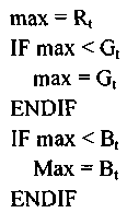
Нормализовать целевые значения RGB

Определить масштабный коэффициент

Максимизировать целевые значения RGB

Determine maximum target RGB value
Normalize RGB target values
Determine the scale factor
Maximize target RGB values
На фиг.8 показана блок-схема иллюстративного способа общего преобразования, используемого в обоих описанных способах преобразования цветного и белого режима. В нижеследующих таблицах представлены иллюстративные реализации каждого подмодуля способа общего преобразования.FIG. 8 is a flowchart of an illustrative general conversion method used in both the described color and white mode conversion methods. The following tables provide illustrative implementations of each submodule of the general conversion method.
Переход интенсивности можно выполнять и реализовывать, как описано в нижеследующей таблице.The intensity transition can be performed and implemented as described in the table below.
Целевая интенсивность % (TI)
Оставшееся время перехода интенсивности (RITT)Current Intensity% (CI)
Target Intensity% (TI)
Remaining Intensity Transition Time (RITT)
Оставшееся время переходаCurrent intensity
Remaining Transition Time
![]()
![]()
Переход цветности можно выполнять и реализовывать, как описано в нижеследующей таблице.The color transition can be performed and implemented as described in the table below.
Цель целевого датчика для красного, зеленого и синего (TSTX)
Оставшееся время перехода цветности (RCTT)Current Sensor Target for Red, Green, and Blue (CST X )
Target Sensor Target for Red, Green, and Blue (TST X )
Remaining Color Transition Time (RCTT)
Оставшееся время перехода цветностиCurrent Sensor Target for Red, Green, and Blue (CST X )
Remaining color transition time

Масштабирование RtGtBt можно выполнять и реализовывать, как описано в нижеследующей таблице.The scaling R t G t B t can be performed and implemented as described in the table below.
Текущая интенсивность
Кривая затемненияCurrent R t G t B t
Current intensity
Dimming curve
Активный Gt=Текущий Gt * DCT(Кривая затемнения, текущая интенсивность)
Активный Bt=Текущий Bt * DCT(Кривая затемнения, текущая интенсивность)Active R t = Current R t * DCT (Dimming curve, current intensity)
Active G t = Current G t * DCT (Dimming curve, current intensity)
Active B t = Current B t * DCT (Dimming curve, current intensity)
Пример 11Example 11
Иллюстративный вариант осуществления системы обратной связи и управления, в которой используется пропорционально-интегральная (ПИ) схема управления на основе обратной связи, схематически показан на фиг.9. Пример можно реализовать с использованием уравнений, представленных в нижеследующей таблице. Как показано, вариант осуществления не выводит сигнал производной (D) из сигнала разности между контрольной точкой и мгновенным выходом. Легко видеть, что существует совокупность альтернативных комбинаций элементов управления P, I или D.An exemplary embodiment of a feedback and control system that uses a proportional-integral (PI) feedback-based control circuit is shown schematically in FIG. 9. An example can be implemented using the equations presented in the table below. As shown, the embodiment does not derive the derivative (D) signal from the difference signal between the control point and the instantaneous output. It is easy to see that there is a collection of alternative combinations of controls P, I, or D.
Y(RGB) - измеренные значения фотодиода с температурной поправкой
![]()
Y (RGB) - measured values of the temperature-corrected photodiode
![]()
![]()
PWM(RGB) - форма волны ШИМ, выводимая на формирователи СИД ![]()
PWM (RGB) - PWM waveform output to LED drivers
KI - постоянная интегрированияK P - proportionality factor
K I - integration constant

Очевидно, что вышеприведенные варианты осуществления изобретения носят иллюстративный характер и допускают разнообразные изменения. Такие настоящие и будущие изменения не следует рассматривать как отход от сущности и объема изобретения, и все подобные модификации, что очевидно специалисту в данной области техники, подлежат включению в объем нижеследующей формулы изобретения.Obviously, the foregoing embodiments are illustrative and subject to various changes. Such present and future changes should not be construed as a departure from the essence and scope of the invention, and all such modifications, which are obvious to a person skilled in the art, should be included in the scope of the following claims.
Claims (22)
a) собирают данные датчиков, представляющие смешанный свет,
b) обеспечивают данные контрольной точки, представляющие требуемый смешанный свет,
c) преобразуют данные датчиков в первые данные, выраженные в координатах заранее определенной системы цветовых координат,
d) преобразуют данные контрольной точки во вторые данные, выраженные в координатах упомянутой заранее определенной системы цветовых координат,
e) сравнивают первые и вторые данные и определяют разность между первыми и вторыми данными,
f) регулируют упомянутые прямые токи в ответ на разность между первыми и вторыми данными, для того чтобы уменьшить разность между упомянутыми первыми данными и упомянутыми вторыми данными, и повторяют этапы (a)-(f) до тех пор, пока абсолютное значение упомянутой разности не упадет ниже заранее определенного порога.1. A method for controlling one or more light emitting elements (SEE) excited by direct currents for generating mixed light, said method comprising the steps of:
a) collect sensor data representing mixed light,
b) provide control point data representing the desired mixed light,
c) convert the sensor data into first data expressed in the coordinates of a predetermined color coordinate system,
d) converting the control point data into second data expressed in the coordinates of said predetermined color coordinate system,
e) comparing the first and second data and determining the difference between the first and second data,
f) adjusting said forward currents in response to a difference between the first and second data in order to reduce the difference between said first data and said second data, and repeating steps (a) to (f) until the absolute value of said difference will fall below a predetermined threshold.
a) один или более оптических датчиков для сбора данных датчиков, представляющих смешанный свет,
b) пользовательский интерфейс для обеспечения данных контрольной точки, представляющих требуемый смешанный свет,
c) контроллер, причем контроллер преобразует данные датчиков в первые данные, выраженные в координатах заранее определенной системы цветовых координат, причем контроллер дополнительно преобразует данные контрольной точки во вторые данные, выраженные в координатах упомянутой заранее определенной системы цветовых координат, причем контроллер дополнительно сравнивает первые и вторые данные и определяет разность между первыми и вторыми данными, причем контроллер дополнительно регулирует упомянутые прямые токи в ответ на разность между первыми и вторыми данными, при этом контроллер выполнен с возможностью уменьшать разность между упомянутыми первыми данными и упомянутыми вторыми данными, пока абсолютное значение упомянутой разности не упадет ниже заранее определенного порога.13. A system for controlling one or more light emitting elements (SEEs) excited by direct currents to generate mixed light, the system comprising
a) one or more optical sensors for collecting sensor data representing mixed light,
b) a user interface for providing control point data representing the desired mixed light,
c) a controller, wherein the controller converts the sensor data into first data expressed in the coordinates of a predetermined color coordinate system, the controller further converting the control point data into second data expressed in the coordinates of the predetermined color coordinate system, the controller further comparing the first and second data and determines the difference between the first and second data, and the controller further adjusts said forward currents in response to the difference between first and second data, while the controller is configured to reduce the difference between said first data and said second data until the absolute value of said difference falls below a predetermined threshold.
Applications Claiming Priority (5)
| Application Number | Priority Date | Filing Date | Title |
|---|---|---|---|
| US86953806P | 2006-12-11 | 2006-12-11 | |
| US60/869,538 | 2006-12-11 | ||
| CA2570952 | 2006-12-12 | ||
| CA2,570,952 | 2006-12-12 | ||
| PCT/CA2007/002218 WO2008070976A1 (en) | 2006-12-11 | 2007-12-11 | Luminaire control system and method |
Publications (2)
| Publication Number | Publication Date |
|---|---|
| RU2009126539A RU2009126539A (en) | 2011-01-20 |
| RU2470496C2 true RU2470496C2 (en) | 2012-12-20 |
Family
ID=39511194
Family Applications (1)
| Application Number | Title | Priority Date | Filing Date |
|---|---|---|---|
| RU2009126539/07A RU2470496C2 (en) | 2006-12-11 | 2007-12-11 | System and method of control over illuminators |
Country Status (7)
| Country | Link |
|---|---|
| US (1) | US7868562B2 (en) |
| EP (1) | EP2092796A4 (en) |
| CN (1) | CN101558688A (en) |
| BR (1) | BRPI0720017A2 (en) |
| CA (1) | CA2708978C (en) |
| RU (1) | RU2470496C2 (en) |
| WO (1) | WO2008070976A1 (en) |
Cited By (5)
| Publication number | Priority date | Publication date | Assignee | Title |
|---|---|---|---|---|
| RU2675253C2 (en) * | 2013-06-04 | 2018-12-18 | Филипс Лайтинг Холдинг Б.В. | Lighting system for illuminating environment and method of starting installation of program on programmable controller |
| RU2687074C1 (en) * | 2018-05-07 | 2019-05-07 | Общество с ограниченной ответственностью "Торговый дом Загар" | Expansion method of effective mercury lamp emitting zone |
| RU2693870C1 (en) * | 2018-10-11 | 2019-07-05 | Общество с ограниченной ответственностью "Торговый дом Загар" | Method for output differentiated acceleration of luminous flux power to operating level when mercury lamps are switched on |
| RU2765299C2 (en) * | 2015-12-24 | 2022-01-28 | Ваттлюкс | Intensity configuration of light sources composing lighting system |
| RU217466U1 (en) * | 2022-08-03 | 2023-04-03 | Федеральное государственное бюджетное учреждение науки Институт сильноточной электроники Сибирского отделения Российской академии наук (ИСЭ СО РАН) | Device for ultraviolet irradiation |
Families Citing this family (143)
| Publication number | Priority date | Publication date | Assignee | Title |
|---|---|---|---|---|
| US20050259424A1 (en) * | 2004-05-18 | 2005-11-24 | Zampini Thomas L Ii | Collimating and controlling light produced by light emitting diodes |
| US7766511B2 (en) * | 2006-04-24 | 2010-08-03 | Integrated Illumination Systems | LED light fixture |
| KR100758987B1 (en) * | 2006-09-26 | 2007-09-17 | 삼성전자주식회사 | A led lighting device and a method for controlling the same |
| US8093825B1 (en) | 2006-11-13 | 2012-01-10 | Cypress Semiconductor Corporation | Control circuit for optical transducers |
| US8129924B2 (en) | 2006-11-13 | 2012-03-06 | Cypress Semiconductor Corporation | Stochastic signal density modulation for optical transducer control |
| US7729941B2 (en) | 2006-11-17 | 2010-06-01 | Integrated Illumination Systems, Inc. | Apparatus and method of using lighting systems to enhance brand recognition |
| WO2008066198A1 (en) * | 2006-12-01 | 2008-06-05 | Hitachi Metals, Ltd. | Laminated bandpass filter, high-frequency part and communication apparatus utilizing them |
| US8013538B2 (en) | 2007-01-26 | 2011-09-06 | Integrated Illumination Systems, Inc. | TRI-light |
| US8044612B2 (en) * | 2007-01-30 | 2011-10-25 | Cypress Semiconductor Corporation | Method and apparatus for networked illumination devices |
| US8742686B2 (en) * | 2007-09-24 | 2014-06-03 | Integrated Illumination Systems, Inc. | Systems and methods for providing an OEM level networked lighting system |
| DE102007059130A1 (en) * | 2007-12-07 | 2009-06-10 | Osram Gesellschaft mit beschränkter Haftung | Method and arrangement for setting a color location and luminous system |
| US8255487B2 (en) * | 2008-05-16 | 2012-08-28 | Integrated Illumination Systems, Inc. | Systems and methods for communicating in a lighting network |
| US8853956B2 (en) * | 2008-06-25 | 2014-10-07 | Koninklijke Philips N.V. | Organic light emitting diode driver arrangement |
| DK2344939T3 (en) | 2008-09-24 | 2018-06-25 | Luminator Holding Lp | Methods and systems for maintaining the illumination intensity of light emitting diodes |
| EP2329186B1 (en) * | 2008-09-24 | 2018-02-21 | B/E Aerospace Inc. | An aircraft led washlight system and method for controlling same |
| US20160053977A1 (en) | 2008-09-24 | 2016-02-25 | B/E Aerospace, Inc. | Flexible led lighting element |
| US9018853B2 (en) * | 2008-09-24 | 2015-04-28 | B/E Aerospace, Inc. | Methods, apparatus and articles of manufacture to calibrate lighting units |
| DE102008057347A1 (en) * | 2008-11-14 | 2010-05-20 | Osram Opto Semiconductors Gmbh | Optoelectronic device |
| JP5852442B2 (en) | 2008-11-17 | 2016-02-03 | エクスプレス イメージング システムズ,エルエルシーExpress Imaging Systems,Llc | Electronic control device and method for adjusting power supply for solid state lighting |
| DE102008064149A1 (en) * | 2008-12-19 | 2010-07-01 | Osram Opto Semiconductors Gmbh | Optoelectronic device |
| KR20100072762A (en) * | 2008-12-22 | 2010-07-01 | 삼성전자주식회사 | Apparatus for providing information of object, apparatus for detecting object, and system for detecting object |
| US10485062B2 (en) * | 2009-11-17 | 2019-11-19 | Ledvance Llc | LED power-supply detection and control |
| US9326346B2 (en) | 2009-01-13 | 2016-04-26 | Terralux, Inc. | Method and device for remote sensing and control of LED lights |
| US8358085B2 (en) | 2009-01-13 | 2013-01-22 | Terralux, Inc. | Method and device for remote sensing and control of LED lights |
| US20100214282A1 (en) | 2009-02-24 | 2010-08-26 | Dolby Laboratories Licensing Corporation | Apparatus for providing light source modulation in dual modulator displays |
| US8585245B2 (en) | 2009-04-23 | 2013-11-19 | Integrated Illumination Systems, Inc. | Systems and methods for sealing a lighting fixture |
| US8872964B2 (en) | 2009-05-20 | 2014-10-28 | Express Imaging Systems, Llc | Long-range motion detection for illumination control |
| US9713211B2 (en) | 2009-09-24 | 2017-07-18 | Cree, Inc. | Solid state lighting apparatus with controllable bypass circuits and methods of operation thereof |
| US8901845B2 (en) | 2009-09-24 | 2014-12-02 | Cree, Inc. | Temperature responsive control for lighting apparatus including light emitting devices providing different chromaticities and related methods |
| US10264637B2 (en) | 2009-09-24 | 2019-04-16 | Cree, Inc. | Solid state lighting apparatus with compensation bypass circuits and methods of operation thereof |
| US8878454B2 (en) * | 2009-12-09 | 2014-11-04 | Tyco Electronics Corporation | Solid state lighting system |
| TWI413446B (en) * | 2010-02-11 | 2013-10-21 | Univ Nat Taiwan | Poly-chromatic light-emitting diode (led) lighting system |
| EP2539227A4 (en) * | 2010-02-25 | 2014-04-02 | Be Aerospace Inc | An aircraft led washlight system and method for controlling same |
| WO2011106695A1 (en) | 2010-02-25 | 2011-09-01 | B/E Aerospace, Inc. | Led lighting element |
| WO2011106661A1 (en) | 2010-02-25 | 2011-09-01 | B/E Aerospace, Inc. | Calibration method for led lighting systems |
| US8476836B2 (en) | 2010-05-07 | 2013-07-02 | Cree, Inc. | AC driven solid state lighting apparatus with LED string including switched segments |
| EP2583535A1 (en) * | 2010-06-18 | 2013-04-24 | B/E Aerospace Inc. | Modular light emitting diode system for vehicle illumination |
| GB2481579B (en) | 2010-06-25 | 2014-11-26 | Enmodus Ltd | Monitoring of power-consumption |
| US10044402B2 (en) | 2010-06-25 | 2018-08-07 | Enmodus Limited | Timing synchronization for wired communications |
| US8384294B2 (en) | 2010-10-05 | 2013-02-26 | Electronic Theatre Controls, Inc. | System and method for color creation and matching |
| TWI550581B (en) * | 2010-12-17 | 2016-09-21 | 杜比實驗室特許公司 | Method and apparatus for image display, computer readable storage medium and computing device |
| US8723450B2 (en) | 2011-01-12 | 2014-05-13 | Electronics Theatre Controls, Inc. | System and method for controlling the spectral content of an output of a light fixture |
| US8593074B2 (en) * | 2011-01-12 | 2013-11-26 | Electronic Theater Controls, Inc. | Systems and methods for controlling an output of a light fixture |
| US10098197B2 (en) | 2011-06-03 | 2018-10-09 | Cree, Inc. | Lighting devices with individually compensating multi-color clusters |
| US10178723B2 (en) | 2011-06-03 | 2019-01-08 | Cree, Inc. | Systems and methods for controlling solid state lighting devices and lighting apparatus incorporating such systems and/or methods |
| US9066381B2 (en) | 2011-03-16 | 2015-06-23 | Integrated Illumination Systems, Inc. | System and method for low level dimming |
| US8950892B2 (en) | 2011-03-17 | 2015-02-10 | Cree, Inc. | Methods for combining light emitting devices in a white light emitting apparatus that mimics incandescent dimming characteristics and solid state lighting apparatus for general illumination that mimic incandescent dimming characteristics |
| US8901825B2 (en) | 2011-04-12 | 2014-12-02 | Express Imaging Systems, Llc | Apparatus and method of energy efficient illumination using received signals |
| CN102769961B (en) * | 2011-05-05 | 2015-03-18 | 光宝电子(广州)有限公司 | Alternating-current lighting device |
| US9839083B2 (en) | 2011-06-03 | 2017-12-05 | Cree, Inc. | Solid state lighting apparatus and circuits including LED segments configured for targeted spectral power distribution and methods of operating the same |
| JP5969023B2 (en) * | 2011-07-15 | 2016-08-10 | コーニンクレッカ フィリップス エヌ ヴェKoninklijke Philips N.V. | Controller for light emitting device |
| US8742671B2 (en) | 2011-07-28 | 2014-06-03 | Cree, Inc. | Solid state lighting apparatus and methods using integrated driver circuitry |
| EP2575411B1 (en) | 2011-09-27 | 2018-07-25 | Infineon Technologies AG | LED driver with compensation of thermally induced colour drift |
| US9140727B2 (en) * | 2011-10-19 | 2015-09-22 | Green Fitness Equipment Company, Llc | Current monitor for indicating condition of attached electrical apparatus |
| US8884553B2 (en) * | 2011-10-19 | 2014-11-11 | Justin Hai | Current monitor for indicating condition of attached electrical apparatus |
| JP6118328B2 (en) * | 2011-10-28 | 2017-04-19 | フィリップス ライティング ホールディング ビー ヴィ | Communication protocol for a lighting system having an embedded processor and system operating with such a protocol |
| US10043960B2 (en) | 2011-11-15 | 2018-08-07 | Cree, Inc. | Light emitting diode (LED) packages and related methods |
| US9360198B2 (en) | 2011-12-06 | 2016-06-07 | Express Imaging Systems, Llc | Adjustable output solid-state lighting device |
| EP2603055A1 (en) * | 2011-12-09 | 2013-06-12 | Eaton Industries GmbH | Method for controlling a multiple colour signal assembly and multiple colour signal assembly |
| WO2013090904A1 (en) | 2011-12-16 | 2013-06-20 | Terralux, Inc. | System and methods of applying bleed circuits in led lamps |
| US9204519B2 (en) | 2012-02-25 | 2015-12-01 | Pqj Corp | Control system with user interface for lighting fixtures |
| US9497393B2 (en) | 2012-03-02 | 2016-11-15 | Express Imaging Systems, Llc | Systems and methods that employ object recognition |
| US9192008B2 (en) | 2012-03-26 | 2015-11-17 | B/E Aerospace, Inc. | Reduced-size modular LED washlight component |
| CN103424184A (en) * | 2012-05-14 | 2013-12-04 | 富泰华工业(深圳)有限公司 | Light-intensity test device |
| US10721808B2 (en) | 2012-07-01 | 2020-07-21 | Ideal Industries Lighting Llc | Light fixture control |
| US9572226B2 (en) | 2012-07-01 | 2017-02-14 | Cree, Inc. | Master/slave arrangement for lighting fixture modules |
| US9980350B2 (en) | 2012-07-01 | 2018-05-22 | Cree, Inc. | Removable module for a lighting fixture |
| US9723673B2 (en) | 2012-07-01 | 2017-08-01 | Cree, Inc. | Handheld device for merging groups of lighting fixtures |
| US9872367B2 (en) | 2012-07-01 | 2018-01-16 | Cree, Inc. | Handheld device for grouping a plurality of lighting fixtures |
| RU2647494C2 (en) * | 2012-07-09 | 2018-03-16 | Филипс Лайтинг Холдинг Б.В. | Method of controlling lighting device |
| US8894437B2 (en) | 2012-07-19 | 2014-11-25 | Integrated Illumination Systems, Inc. | Systems and methods for connector enabling vertical removal |
| ES2902680T3 (en) * | 2012-07-24 | 2022-03-29 | Building Robotics Inc | Distributed lighting control |
| US9131552B2 (en) | 2012-07-25 | 2015-09-08 | Express Imaging Systems, Llc | Apparatus and method of operating a luminaire |
| US9066405B2 (en) | 2012-07-30 | 2015-06-23 | Cree, Inc. | Lighting device with variable color rendering based on ambient light |
| US8896215B2 (en) | 2012-09-05 | 2014-11-25 | Express Imaging Systems, Llc | Apparatus and method for schedule based operation of a luminaire |
| KR102118309B1 (en) | 2012-09-19 | 2020-06-03 | 돌비 레버러토리즈 라이쎈싱 코오포레이션 | Quantum dot/remote phosphor display system improvements |
| US9379578B2 (en) | 2012-11-19 | 2016-06-28 | Integrated Illumination Systems, Inc. | Systems and methods for multi-state power management |
| US9913348B2 (en) | 2012-12-19 | 2018-03-06 | Cree, Inc. | Light fixtures, systems for controlling light fixtures, and methods of controlling fixtures and methods of controlling lighting control systems |
| US9420665B2 (en) | 2012-12-28 | 2016-08-16 | Integration Illumination Systems, Inc. | Systems and methods for continuous adjustment of reference signal to control chip |
| US9485814B2 (en) | 2013-01-04 | 2016-11-01 | Integrated Illumination Systems, Inc. | Systems and methods for a hysteresis based driver using a LED as a voltage reference |
| US10264638B2 (en) | 2013-01-15 | 2019-04-16 | Cree, Inc. | Circuits and methods for controlling solid state lighting |
| US10231300B2 (en) | 2013-01-15 | 2019-03-12 | Cree, Inc. | Systems and methods for controlling solid state lighting during dimming and lighting apparatus incorporating such systems and/or methods |
| KR102115146B1 (en) | 2013-03-08 | 2020-05-26 | 돌비 레버러토리즈 라이쎈싱 코오포레이션 | Techniques for dual modulation display with light conversion |
| US9307613B2 (en) | 2013-03-11 | 2016-04-05 | Lutron Electronics Co., Inc. | Load control device with an adjustable control curve |
| US9992841B2 (en) * | 2013-04-19 | 2018-06-05 | Lutron Electronics Co., Inc. | Systems and methods for controlling color temperature |
| US9538603B2 (en) * | 2013-04-19 | 2017-01-03 | Lutron Electronics Co., Inc. | Systems and methods for controlling color temperature |
| US9265119B2 (en) | 2013-06-17 | 2016-02-16 | Terralux, Inc. | Systems and methods for providing thermal fold-back to LED lights |
| WO2015006852A1 (en) * | 2013-07-19 | 2015-01-22 | Institut National D'optique | Controlled operation of a led lighting system at a target output color |
| US9013467B2 (en) | 2013-07-19 | 2015-04-21 | Institut National D'optique | Controlled operation of a LED lighting system at a target output color |
| US9466443B2 (en) | 2013-07-24 | 2016-10-11 | Express Imaging Systems, Llc | Photocontrol for luminaire consumes very low power |
| US9414449B2 (en) | 2013-11-18 | 2016-08-09 | Express Imaging Systems, Llc | High efficiency power controller for luminaire |
| CN103747373A (en) * | 2013-12-31 | 2014-04-23 | 广州市夜太阳舞台灯光音响设备有限公司 | Sound box with LED (light emitting diode) color light effect |
| US10154569B2 (en) | 2014-01-06 | 2018-12-11 | Cree, Inc. | Power over ethernet lighting fixture |
| WO2015116812A1 (en) * | 2014-01-30 | 2015-08-06 | Express Imaging Systems, Llc | Ambient light control in solid state lamps and luminaires |
| US9603218B1 (en) * | 2014-03-13 | 2017-03-21 | Cooper Technologies Company | Controlled color transition |
| WO2015148244A2 (en) | 2014-03-26 | 2015-10-01 | Dolby Laboratories Licensing Corporation | Global light compensation in a variety of displays |
| WO2015148724A1 (en) | 2014-03-26 | 2015-10-01 | Pqj Corp | System and method for communicating with and for controlling of programmable apparatuses |
| US9338851B2 (en) | 2014-04-10 | 2016-05-10 | Institut National D'optique | Operation of a LED lighting system at a target output color using a color sensor |
| US9723680B2 (en) | 2014-05-30 | 2017-08-01 | Cree, Inc. | Digitally controlled driver for lighting fixture |
| JP6659666B2 (en) * | 2014-08-11 | 2020-03-04 | シグニファイ ホールディング ビー ヴィSignify Holding B.V. | Light system interface and method |
| US9713222B2 (en) | 2014-08-12 | 2017-07-18 | Electronic Theatre Controls, Inc. | System and method for controlling a plurality of light fixture outputs |
| US9144140B1 (en) | 2014-08-12 | 2015-09-22 | Electronic Theatre Controls, Inc. | System and method for controlling a plurality of light fixture outputs |
| US9810944B2 (en) | 2014-08-21 | 2017-11-07 | Dolby Laboratories Licensing Corporation | Techniques for dual modulation with light conversion |
| DE102015002639A1 (en) * | 2015-03-03 | 2016-09-08 | Diehl Aerospace Gmbh | Control of color lights with a brightness channel |
| US9462662B1 (en) | 2015-03-24 | 2016-10-04 | Express Imaging Systems, Llc | Low power photocontrol for luminaire |
| US9681510B2 (en) | 2015-03-26 | 2017-06-13 | Cree, Inc. | Lighting device with operation responsive to geospatial position |
| US10030844B2 (en) | 2015-05-29 | 2018-07-24 | Integrated Illumination Systems, Inc. | Systems, methods and apparatus for illumination using asymmetrical optics |
| US10060599B2 (en) | 2015-05-29 | 2018-08-28 | Integrated Illumination Systems, Inc. | Systems, methods and apparatus for programmable light fixtures |
| US9900957B2 (en) | 2015-06-11 | 2018-02-20 | Cree, Inc. | Lighting device including solid state emitters with adjustable control |
| TWI670991B (en) * | 2015-06-24 | 2019-09-01 | 財團法人工業技術研究院 | Lighting apparatus of adjustable color temperature and method for adjusting color temperature thereof |
| ES2906225T3 (en) * | 2015-07-14 | 2022-04-13 | Signify Holding Bv | Procedure for configuring a device in a lighting system |
| US9538612B1 (en) | 2015-09-03 | 2017-01-03 | Express Imaging Systems, Llc | Low power photocontrol for luminaire |
| US10359158B2 (en) * | 2015-09-30 | 2019-07-23 | Current Lighting Solutions, Llc | Lighting selection system and method |
| US10292247B2 (en) * | 2015-10-16 | 2019-05-14 | Delight Innovative Technologies Limited | Intelligent installation method of indoor lighting system |
| US9854654B2 (en) | 2016-02-03 | 2017-12-26 | Pqj Corp | System and method of control of a programmable lighting fixture with embedded memory |
| DE102016103677A1 (en) * | 2016-03-01 | 2017-09-07 | Technische Universität Darmstadt | Method for controlling a lighting device and lighting device |
| DE102016104440A1 (en) * | 2016-03-10 | 2017-09-14 | Inova Semiconductors Gmbh | Method and device for brightness compensation of an LED |
| US9924582B2 (en) | 2016-04-26 | 2018-03-20 | Express Imaging Systems, Llc | Luminaire dimming module uses 3 contact NEMA photocontrol socket |
| CN106102222A (en) * | 2016-06-19 | 2016-11-09 | 张力 | A kind of method and system being automatically adjusted electric light light |
| US9967944B2 (en) | 2016-06-22 | 2018-05-08 | Cree, Inc. | Dimming control for LED-based luminaires |
| US10230296B2 (en) | 2016-09-21 | 2019-03-12 | Express Imaging Systems, Llc | Output ripple reduction for power converters |
| US9985429B2 (en) | 2016-09-21 | 2018-05-29 | Express Imaging Systems, Llc | Inrush current limiter circuit |
| US10595380B2 (en) | 2016-09-27 | 2020-03-17 | Ideal Industries Lighting Llc | Lighting wall control with virtual assistant |
| US10451229B2 (en) | 2017-01-30 | 2019-10-22 | Ideal Industries Lighting Llc | Skylight fixture |
| US10465869B2 (en) | 2017-01-30 | 2019-11-05 | Ideal Industries Lighting Llc | Skylight fixture |
| US10904992B2 (en) | 2017-04-03 | 2021-01-26 | Express Imaging Systems, Llc | Systems and methods for outdoor luminaire wireless control |
| US11375599B2 (en) | 2017-04-03 | 2022-06-28 | Express Imaging Systems, Llc | Systems and methods for outdoor luminaire wireless control |
| CN111670608B (en) | 2017-10-25 | 2022-07-15 | 美国尼可有限公司 | Method and system for power supply control |
| US20210329850A1 (en) * | 2018-04-19 | 2021-10-28 | AGrow-Ray Technologies, Inc. | Adaptive photosynthetically active radiation (par) sensor with daylight integral (dli) control system incorporating lumen maintenance |
| CN108419340B (en) * | 2018-05-09 | 2024-07-05 | 华域视觉科技(上海)有限公司 | Method for realizing one-lamp multi-purpose of signal lamp and multi-signal functional signal lamp photoelectric device |
| WO2020003399A1 (en) * | 2018-06-27 | 2020-01-02 | オリンパス株式会社 | Endoscopic system |
| CN108958748A (en) * | 2018-06-29 | 2018-12-07 | 中山市中大半导体照明技术研究有限公司 | Device data in file is exported to the method for online DALI lighting system |
| JP6994609B1 (en) | 2018-12-20 | 2022-01-14 | シグニファイ ホールディング ビー ヴィ | Control module for controlling luminaires |
| US11317497B2 (en) | 2019-06-20 | 2022-04-26 | Express Imaging Systems, Llc | Photocontroller and/or lamp with photocontrols to control operation of lamp |
| US10772173B1 (en) | 2019-08-21 | 2020-09-08 | Electronic Theatre Controls, Inc. | Systems, methods, and devices for controlling one or more LED light fixtures |
| US11232684B2 (en) | 2019-09-09 | 2022-01-25 | Appleton Grp Llc | Smart luminaire group control using intragroup communication |
| US11343898B2 (en) | 2019-09-20 | 2022-05-24 | Appleton Grp Llc | Smart dimming and sensor failure detection as part of built in daylight harvesting inside the luminaire |
| NL2023938B1 (en) * | 2019-10-02 | 2021-05-31 | Eldolab Holding Bv | Method of multi-mode color control by an LED driver |
| US10801714B1 (en) | 2019-10-03 | 2020-10-13 | CarJamz, Inc. | Lighting device |
| US11212887B2 (en) | 2019-11-04 | 2021-12-28 | Express Imaging Systems, Llc | Light having selectively adjustable sets of solid state light sources, circuit and method of operation thereof, to provide variable output characteristics |
| US11326951B2 (en) * | 2019-12-06 | 2022-05-10 | Columbia Insurance Company | System for colorimetry and a transformation from a non-uniform color space to a substantially uniform color space |
| CN115517019A (en) | 2020-03-31 | 2022-12-23 | 路创技术有限责任公司 | Color temperature control of lighting devices |
| CN112118030B (en) * | 2020-08-27 | 2022-02-11 | 深圳市力合微电子股份有限公司 | Pre-response method suitable for pan DALI system |
Citations (5)
| Publication number | Priority date | Publication date | Assignee | Title |
|---|---|---|---|---|
| CA2258049A1 (en) * | 1996-06-13 | 1997-12-18 | Gentex Corporation | Illuminator assembly incorporating light emitting diodes |
| US6552495B1 (en) * | 2001-12-19 | 2003-04-22 | Koninklijke Philips Electronics N.V. | Adaptive control system and method with spatial uniform color metric for RGB LED based white light illumination |
| WO2003053108A1 (en) * | 2001-12-19 | 2003-06-26 | Koninklijke Philips Electronics N.V. | Led based white light control system |
| RU2004106759A (en) * | 2004-03-10 | 2005-08-20 | Александр Леонидович Ногинов (RU) | DECORATIVE MULTI-COLOR LAMP WITH CONTROL DEVICE |
| US20060022999A1 (en) * | 2004-07-28 | 2006-02-02 | Lee Joon C | Methods and apparatus for setting the color point of an LED light source |
Family Cites Families (55)
| Publication number | Priority date | Publication date | Assignee | Title |
|---|---|---|---|---|
| JPS54111720A (en) | 1978-02-22 | 1979-09-01 | Nissan Motor | Method of indicating color |
| JPS60163102A (en) | 1984-02-03 | 1985-08-26 | Nec Corp | Pid temperature control circuit |
| DE3546599C2 (en) | 1984-11-20 | 1993-06-03 | Olympus Optical Co., Ltd., Tokio/Tokyo, Jp | |
| US5769527A (en) | 1986-07-17 | 1998-06-23 | Vari-Lite, Inc. | Computer controlled lighting system with distributed control resources |
| US5329431A (en) | 1986-07-17 | 1994-07-12 | Vari-Lite, Inc. | Computer controlled lighting system with modular control resources |
| US4962687A (en) | 1988-09-06 | 1990-10-16 | Belliveau Richard S | Variable color lighting system |
| JPH02106082A (en) | 1988-10-14 | 1990-04-18 | Eastman Kodatsuku Japan Kk | Semiconductor light emitting element |
| JPH02155045A (en) | 1988-12-07 | 1990-06-14 | Aputo Instr Kk | Truth value converter |
| JPH02256193A (en) | 1989-03-29 | 1990-10-16 | Toshiba Lighting & Technol Corp | Lighting control device |
| EP0482680A1 (en) | 1991-02-27 | 1992-04-29 | Koninklijke Philips Electronics N.V. | Programmable illumination system |
| JPH0588704A (en) | 1991-09-27 | 1993-04-09 | Fuji Electric Co Ltd | Pid controller |
| JPH0676961A (en) | 1992-08-26 | 1994-03-18 | Matsushita Electric Works Ltd | Variable color lighting system |
| NZ276610A (en) | 1993-11-12 | 1998-03-25 | Colortran Inc | Theatrical lighting control using local area network and node controllers and at least one rack of a plurality of effect control elements |
| US5406176A (en) | 1994-01-12 | 1995-04-11 | Aurora Robotics Limited | Computer controlled stage lighting system |
| KR100194377B1 (en) | 1996-04-08 | 1999-06-15 | 윤종용 | Apparatus and Method for Gain Determination of Feed Controller Using Genetic Theory |
| US5783909A (en) | 1997-01-10 | 1998-07-21 | Relume Corporation | Maintaining LED luminous intensity |
| US6777891B2 (en) | 1997-08-26 | 2004-08-17 | Color Kinetics, Incorporated | Methods and apparatus for controlling devices in a networked lighting system |
| US6608453B2 (en) | 1997-08-26 | 2003-08-19 | Color Kinetics Incorporated | Methods and apparatus for controlling devices in a networked lighting system |
| US7353071B2 (en) | 1999-07-14 | 2008-04-01 | Philips Solid-State Lighting Solutions, Inc. | Method and apparatus for authoring and playing back lighting sequences |
| TW408497B (en) | 1997-11-25 | 2000-10-11 | Matsushita Electric Works Ltd | LED illuminating apparatus |
| EP1075706A4 (en) | 1998-04-27 | 2001-07-18 | Peter A Hochstein | Maintaining led luminous intensity |
| US6188181B1 (en) | 1998-08-25 | 2001-02-13 | Lutron Electronics Co., Inc. | Lighting control system for different load types |
| US6430313B1 (en) | 1998-09-10 | 2002-08-06 | Intel Corporation | Using a minimal number of parameters for correcting the response of color image sensors |
| US6208073B1 (en) | 1998-09-15 | 2001-03-27 | Opto Tech Corp. | Smart light emitting diode cluster and system |
| US6482004B1 (en) | 1999-03-26 | 2002-11-19 | Ivoclar Ag | Light curing device and method for curing light-polymerizable dental material |
| US6462669B1 (en) | 1999-04-06 | 2002-10-08 | E. P . Survivors Llc | Replaceable LED modules |
| US6255786B1 (en) | 2000-04-19 | 2001-07-03 | George Yen | Light emitting diode lighting device |
| US7161556B2 (en) | 2000-08-07 | 2007-01-09 | Color Kinetics Incorporated | Systems and methods for programming illumination devices |
| US6441558B1 (en) * | 2000-12-07 | 2002-08-27 | Koninklijke Philips Electronics N.V. | White LED luminary light control system |
| US6507159B2 (en) | 2001-03-29 | 2003-01-14 | Koninklijke Philips Electronics N.V. | Controlling method and system for RGB based LED luminary |
| US20040225811A1 (en) | 2001-04-04 | 2004-11-11 | Fosler Ross M. | Digital addressable lighting interface bridge |
| US6741351B2 (en) | 2001-06-07 | 2004-05-25 | Koninklijke Philips Electronics N.V. | LED luminaire with light sensor configurations for optical feedback |
| US6617795B2 (en) | 2001-07-26 | 2003-09-09 | Koninklijke Philips Electronics N.V. | Multichip LED package with in-package quantitative and spectral sensing capability and digital signal output |
| EP1416219B1 (en) | 2001-08-09 | 2016-06-22 | Everlight Electronics Co., Ltd | Led illuminator and card type led illuminating light source |
| US20030036807A1 (en) | 2001-08-14 | 2003-02-20 | Fosler Ross M. | Multiple master digital addressable lighting interface (DALI) system, method and apparatus |
| US6761470B2 (en) | 2002-02-08 | 2004-07-13 | Lowel-Light Manufacturing, Inc. | Controller panel and system for light and serially networked lighting system |
| GB0204212D0 (en) | 2002-02-22 | 2002-04-10 | Oxley Dev Co Ltd | Led drive circuit |
| US7109974B2 (en) * | 2002-03-05 | 2006-09-19 | Matsushita Electric Industrial Co., Ltd. | Remote control system including an on-screen display (OSD) |
| US8100552B2 (en) | 2002-07-12 | 2012-01-24 | Yechezkal Evan Spero | Multiple light-source illuminating system |
| JP4703101B2 (en) | 2003-02-07 | 2011-06-15 | 日東電工株式会社 | Process control method |
| DE10323689A1 (en) | 2003-05-22 | 2004-12-09 | Patent-Treuhand-Gesellschaft für elektrische Glühlampen mbH | Controllable lighting system with a second communication protocol and devices therefor |
| WO2005009085A1 (en) | 2003-07-23 | 2005-01-27 | Tir Systems Ltd. | Control system for an illumination device incorporating discrete light sources |
| WO2005025277A1 (en) | 2003-09-04 | 2005-03-17 | Koninklijke Philips Electronics, N.V. | Digital addressable lighting interface translation method |
| US7354172B2 (en) | 2004-03-15 | 2008-04-08 | Philips Solid-State Lighting Solutions, Inc. | Methods and apparatus for controlled lighting based on a reference gamut |
| US20050289279A1 (en) | 2004-06-24 | 2005-12-29 | City Theatrical, Inc. | Power supply system and method thereof |
| US7333011B2 (en) | 2004-07-06 | 2008-02-19 | Honeywell International Inc. | LED-based luminaire utilizing optical feedback color and intensity control scheme |
| US7212287B2 (en) | 2004-08-05 | 2007-05-01 | Avago Technologies Ecbu Ip (Singapore) Pte. Ltd. | Providing optical feedback on light color |
| DE102004047669A1 (en) | 2004-09-30 | 2006-04-13 | Patent-Treuhand-Gesellschaft für elektrische Glühlampen mbH | Lighting device and method of control |
| US7205729B2 (en) | 2004-10-07 | 2007-04-17 | Barco, Naamloze Vennootschap | Control system and method for controlling lighting and video devices |
| US7573209B2 (en) | 2004-10-12 | 2009-08-11 | Koninklijke Philips Electronics N.V. | Method and system for feedback and control of a luminaire |
| CA2589238A1 (en) | 2004-11-29 | 2006-06-01 | Tir Systems Ltd. | Integrated modular lighting unit |
| EP1849152A4 (en) | 2004-12-20 | 2012-05-02 | Philips Solid State Lighting | Color management methods and apparatus for lighting |
| US20060193133A1 (en) | 2005-02-25 | 2006-08-31 | Erco Leuchten Gmbh | Lamp |
| US20060226956A1 (en) | 2005-04-07 | 2006-10-12 | Dialight Corporation | LED assembly with a communication protocol for LED light engines |
| WO2006133272A2 (en) | 2005-06-06 | 2006-12-14 | Color Kinetics Incorporated | Methods and apparatus for implementing power cycle control of lighting devices based on network protocols |
-
2007
- 2007-12-11 US US12/001,786 patent/US7868562B2/en active Active
- 2007-12-11 CA CA2708978A patent/CA2708978C/en active Active
- 2007-12-11 BR BRPI0720017A patent/BRPI0720017A2/en not_active Application Discontinuation
- 2007-12-11 WO PCT/CA2007/002218 patent/WO2008070976A1/en active Application Filing
- 2007-12-11 RU RU2009126539/07A patent/RU2470496C2/en active
- 2007-12-11 EP EP07855500.0A patent/EP2092796A4/en not_active Ceased
- 2007-12-12 CN CNA2007800460751A patent/CN101558688A/en active Pending
Patent Citations (5)
| Publication number | Priority date | Publication date | Assignee | Title |
|---|---|---|---|---|
| CA2258049A1 (en) * | 1996-06-13 | 1997-12-18 | Gentex Corporation | Illuminator assembly incorporating light emitting diodes |
| US6552495B1 (en) * | 2001-12-19 | 2003-04-22 | Koninklijke Philips Electronics N.V. | Adaptive control system and method with spatial uniform color metric for RGB LED based white light illumination |
| WO2003053108A1 (en) * | 2001-12-19 | 2003-06-26 | Koninklijke Philips Electronics N.V. | Led based white light control system |
| RU2004106759A (en) * | 2004-03-10 | 2005-08-20 | Александр Леонидович Ногинов (RU) | DECORATIVE MULTI-COLOR LAMP WITH CONTROL DEVICE |
| US20060022999A1 (en) * | 2004-07-28 | 2006-02-02 | Lee Joon C | Methods and apparatus for setting the color point of an LED light source |
Cited By (5)
| Publication number | Priority date | Publication date | Assignee | Title |
|---|---|---|---|---|
| RU2675253C2 (en) * | 2013-06-04 | 2018-12-18 | Филипс Лайтинг Холдинг Б.В. | Lighting system for illuminating environment and method of starting installation of program on programmable controller |
| RU2765299C2 (en) * | 2015-12-24 | 2022-01-28 | Ваттлюкс | Intensity configuration of light sources composing lighting system |
| RU2687074C1 (en) * | 2018-05-07 | 2019-05-07 | Общество с ограниченной ответственностью "Торговый дом Загар" | Expansion method of effective mercury lamp emitting zone |
| RU2693870C1 (en) * | 2018-10-11 | 2019-07-05 | Общество с ограниченной ответственностью "Торговый дом Загар" | Method for output differentiated acceleration of luminous flux power to operating level when mercury lamps are switched on |
| RU217466U1 (en) * | 2022-08-03 | 2023-04-03 | Федеральное государственное бюджетное учреждение науки Институт сильноточной электроники Сибирского отделения Российской академии наук (ИСЭ СО РАН) | Device for ultraviolet irradiation |
Also Published As
| Publication number | Publication date |
|---|---|
| RU2009126539A (en) | 2011-01-20 |
| CA2708978C (en) | 2016-03-15 |
| US7868562B2 (en) | 2011-01-11 |
| BRPI0720017A2 (en) | 2017-01-10 |
| EP2092796A4 (en) | 2016-11-16 |
| CA2708978A1 (en) | 2008-06-19 |
| CN101558688A (en) | 2009-10-14 |
| WO2008070976A1 (en) | 2008-06-19 |
| US20080215279A1 (en) | 2008-09-04 |
| EP2092796A1 (en) | 2009-08-26 |
Similar Documents
| Publication | Publication Date | Title |
|---|---|---|
| RU2470496C2 (en) | System and method of control over illuminators | |
| JP5554992B2 (en) | Lighting fixture control system and method | |
| US7319298B2 (en) | Digitally controlled luminaire system | |
| RU2453078C2 (en) | Method and apparatus for digital control of illumination device | |
| EP2335455B1 (en) | Method and apparatus for controlling and measuring aspects of time-varying combined light | |
| JP5071834B2 (en) | Lighting device and adjustment method | |
| JP4198599B2 (en) | Color control for LED-based light emitters | |
| US20100259182A1 (en) | Light source intensity control system and method | |
| US20080297066A1 (en) | Illumination Device and Method for Controlling an Illumination Device | |
| CN103108469B (en) | Method and device for controlling output light of illuminating device and illuminating system | |
| US20110241552A1 (en) | Method for maximizing the performance of a luminaire | |
| US7436386B2 (en) | Transmission type display device and a method for controlling its display colors | |
| US20110184678A1 (en) | Automated systems and methods for characterizing light-emitting devices | |
| KR100762361B1 (en) | Apparatus and method for being uniform illumination of light source in digital image area, and apparatus and method for testing color of digital image using it | |
| Murdoch | Dynamic color control in multiprimary tunable LED lighting systems | |
| Sisto et al. | Accurate chromatic control and color rendering optimization in LED lighting systems using junction temperature feedback | |
| CA2848855C (en) | Operation of a led lighting system at a target output color using a color sensor | |
| Aldrich | Dynamic solid state lighting |
Legal Events
| Date | Code | Title | Description |
|---|---|---|---|
| PD4A | Correction of name of patent owner | ||
| PC41 | Official registration of the transfer of exclusive right |
Effective date: 20170315 |
|
| PD4A | Correction of name of patent owner |