RU2469756C1 - Moulded layered non-woven fabric containing particles - Google Patents
Moulded layered non-woven fabric containing particles Download PDFInfo
- Publication number
- RU2469756C1 RU2469756C1 RU2011123104/12A RU2011123104A RU2469756C1 RU 2469756 C1 RU2469756 C1 RU 2469756C1 RU 2011123104/12 A RU2011123104/12 A RU 2011123104/12A RU 2011123104 A RU2011123104 A RU 2011123104A RU 2469756 C1 RU2469756 C1 RU 2469756C1
- Authority
- RU
- Russia
- Prior art keywords
- filter element
- particles
- deformation
- fabric
- element according
- Prior art date
Links
- 239000002245 particle Substances 0.000 title claims abstract description 97
- 239000004745 nonwoven fabric Substances 0.000 title claims abstract description 30
- 239000000835 fiber Substances 0.000 claims abstract description 26
- 229920005594 polymer fiber Polymers 0.000 claims abstract description 23
- 239000004744 fabric Substances 0.000 claims abstract description 17
- 229920001169 thermoplastic Polymers 0.000 claims abstract description 17
- 239000004416 thermosoftening plastic Substances 0.000 claims abstract description 16
- 239000000126 substance Substances 0.000 claims abstract description 15
- 239000002594 sorbent Substances 0.000 claims description 10
- 229920000642 polymer Polymers 0.000 claims description 7
- -1 polybutylene Polymers 0.000 claims description 6
- 229920000098 polyolefin Polymers 0.000 claims description 6
- 239000003344 environmental pollutant Substances 0.000 claims description 5
- 231100000719 pollutant Toxicity 0.000 claims description 5
- 229920001971 elastomer Polymers 0.000 claims description 4
- 239000000806 elastomer Substances 0.000 claims description 4
- 238000012856 packing Methods 0.000 claims description 4
- 229920001748 polybutylene Polymers 0.000 claims description 3
- 229920006132 styrene block copolymer Polymers 0.000 claims description 3
- 239000004433 Thermoplastic polyurethane Substances 0.000 claims description 2
- 229920002803 thermoplastic polyurethane Polymers 0.000 claims description 2
- 229920006346 thermoplastic polyester elastomer Polymers 0.000 claims 1
- OKTJSMMVPCPJKN-UHFFFAOYSA-N Carbon Chemical compound [C] OKTJSMMVPCPJKN-UHFFFAOYSA-N 0.000 abstract description 22
- 229910052799 carbon Inorganic materials 0.000 abstract description 8
- 230000000694 effects Effects 0.000 abstract description 4
- 239000004753 textile Substances 0.000 abstract 1
- 238000000034 method Methods 0.000 description 15
- 239000007789 gas Substances 0.000 description 13
- 238000005266 casting Methods 0.000 description 10
- 239000000463 material Substances 0.000 description 10
- 238000000465 moulding Methods 0.000 description 9
- 239000012530 fluid Substances 0.000 description 7
- 239000011347 resin Substances 0.000 description 7
- 229920005989 resin Polymers 0.000 description 7
- 238000013461 design Methods 0.000 description 6
- 238000006073 displacement reaction Methods 0.000 description 6
- 238000001914 filtration Methods 0.000 description 6
- 239000003570 air Substances 0.000 description 5
- 230000000241 respiratory effect Effects 0.000 description 5
- UGFAIRIUMAVXCW-UHFFFAOYSA-N Carbon monoxide Chemical compound [O+]#[C-] UGFAIRIUMAVXCW-UHFFFAOYSA-N 0.000 description 4
- GWEVSGVZZGPLCZ-UHFFFAOYSA-N Titan oxide Chemical compound O=[Ti]=O GWEVSGVZZGPLCZ-UHFFFAOYSA-N 0.000 description 4
- 229910002091 carbon monoxide Inorganic materials 0.000 description 4
- 238000004519 manufacturing process Methods 0.000 description 4
- 239000000203 mixture Substances 0.000 description 4
- 238000012360 testing method Methods 0.000 description 4
- QTBSBXVTEAMEQO-UHFFFAOYSA-N Acetic acid Chemical compound CC(O)=O QTBSBXVTEAMEQO-UHFFFAOYSA-N 0.000 description 3
- WMFOQBRAJBCJND-UHFFFAOYSA-M Lithium hydroxide Chemical compound [Li+].[OH-] WMFOQBRAJBCJND-UHFFFAOYSA-M 0.000 description 3
- 229920001410 Microfiber Polymers 0.000 description 3
- HEMHJVSKTPXQMS-UHFFFAOYSA-M Sodium hydroxide Chemical compound [OH-].[Na+] HEMHJVSKTPXQMS-UHFFFAOYSA-M 0.000 description 3
- PNEYBMLMFCGWSK-UHFFFAOYSA-N aluminium oxide Inorganic materials [O-2].[O-2].[O-2].[Al+3].[Al+3] PNEYBMLMFCGWSK-UHFFFAOYSA-N 0.000 description 3
- 239000012080 ambient air Substances 0.000 description 3
- 239000003054 catalyst Substances 0.000 description 3
- 230000003197 catalytic effect Effects 0.000 description 3
- 238000005516 engineering process Methods 0.000 description 3
- PCHJSUWPFVWCPO-UHFFFAOYSA-N gold Chemical compound [Au] PCHJSUWPFVWCPO-UHFFFAOYSA-N 0.000 description 3
- 229910052737 gold Inorganic materials 0.000 description 3
- 239000010931 gold Substances 0.000 description 3
- 239000003658 microfiber Substances 0.000 description 3
- 239000002105 nanoparticle Substances 0.000 description 3
- 229920000728 polyester Polymers 0.000 description 3
- 239000010457 zeolite Substances 0.000 description 3
- QGZKDVFQNNGYKY-UHFFFAOYSA-N Ammonia Chemical compound N QGZKDVFQNNGYKY-UHFFFAOYSA-N 0.000 description 2
- VTYYLEPIZMXCLO-UHFFFAOYSA-L Calcium carbonate Chemical compound [Ca+2].[O-]C([O-])=O VTYYLEPIZMXCLO-UHFFFAOYSA-L 0.000 description 2
- CURLTUGMZLYLDI-UHFFFAOYSA-N Carbon dioxide Chemical compound O=C=O CURLTUGMZLYLDI-UHFFFAOYSA-N 0.000 description 2
- 229920002633 Kraton (polymer) Polymers 0.000 description 2
- VYPSYNLAJGMNEJ-UHFFFAOYSA-N Silicium dioxide Chemical compound O=[Si]=O VYPSYNLAJGMNEJ-UHFFFAOYSA-N 0.000 description 2
- UIIMBOGNXHQVGW-UHFFFAOYSA-M Sodium bicarbonate Chemical compound [Na+].OC([O-])=O UIIMBOGNXHQVGW-UHFFFAOYSA-M 0.000 description 2
- 239000002253 acid Substances 0.000 description 2
- 150000001875 compounds Chemical class 0.000 description 2
- 239000000383 hazardous chemical Substances 0.000 description 2
- NUJOXMJBOLGQSY-UHFFFAOYSA-N manganese dioxide Chemical compound O=[Mn]=O NUJOXMJBOLGQSY-UHFFFAOYSA-N 0.000 description 2
- 238000005259 measurement Methods 0.000 description 2
- 238000012545 processing Methods 0.000 description 2
- 238000010998 test method Methods 0.000 description 2
- 239000004408 titanium dioxide Substances 0.000 description 2
- IMNIMPAHZVJRPE-UHFFFAOYSA-N triethylenediamine Chemical compound C1CN2CCN1CC2 IMNIMPAHZVJRPE-UHFFFAOYSA-N 0.000 description 2
- XLYOFNOQVPJJNP-UHFFFAOYSA-N water Substances O XLYOFNOQVPJJNP-UHFFFAOYSA-N 0.000 description 2
- JIAARYAFYJHUJI-UHFFFAOYSA-L zinc dichloride Chemical compound [Cl-].[Cl-].[Zn+2] JIAARYAFYJHUJI-UHFFFAOYSA-L 0.000 description 2
- 238000012935 Averaging Methods 0.000 description 1
- QPLDLSVMHZLSFG-UHFFFAOYSA-N Copper oxide Chemical compound [Cu]=O QPLDLSVMHZLSFG-UHFFFAOYSA-N 0.000 description 1
- 239000005751 Copper oxide Substances 0.000 description 1
- XDTMQSROBMDMFD-UHFFFAOYSA-N Cyclohexane Chemical compound C1CCCCC1 XDTMQSROBMDMFD-UHFFFAOYSA-N 0.000 description 1
- KRHYYFGTRYWZRS-UHFFFAOYSA-N Fluorane Chemical compound F KRHYYFGTRYWZRS-UHFFFAOYSA-N 0.000 description 1
- 239000004952 Polyamide Substances 0.000 description 1
- BQCADISMDOOEFD-UHFFFAOYSA-N Silver Chemical compound [Ag] BQCADISMDOOEFD-UHFFFAOYSA-N 0.000 description 1
- 229920013623 Solprene Polymers 0.000 description 1
- 229910021536 Zeolite Inorganic materials 0.000 description 1
- 238000005299 abrasion Methods 0.000 description 1
- 239000003929 acidic solution Substances 0.000 description 1
- 230000002378 acidificating effect Effects 0.000 description 1
- 239000004840 adhesive resin Substances 0.000 description 1
- 229920006223 adhesive resin Polymers 0.000 description 1
- 239000000443 aerosol Substances 0.000 description 1
- 239000012670 alkaline solution Substances 0.000 description 1
- 238000005267 amalgamation Methods 0.000 description 1
- 229910021529 ammonia Inorganic materials 0.000 description 1
- 239000002585 base Substances 0.000 description 1
- 239000011324 bead Substances 0.000 description 1
- 230000002902 bimodal effect Effects 0.000 description 1
- 239000003139 biocide Substances 0.000 description 1
- 229920001400 block copolymer Polymers 0.000 description 1
- 229910000019 calcium carbonate Inorganic materials 0.000 description 1
- 239000001569 carbon dioxide Substances 0.000 description 1
- 229910002092 carbon dioxide Inorganic materials 0.000 description 1
- 208000018747 cerebellar ataxia with neuropathy and bilateral vestibular areflexia syndrome Diseases 0.000 description 1
- 238000006243 chemical reaction Methods 0.000 description 1
- 239000003795 chemical substances by application Substances 0.000 description 1
- 239000004927 clay Substances 0.000 description 1
- 238000004891 communication Methods 0.000 description 1
- 230000006835 compression Effects 0.000 description 1
- 238000007906 compression Methods 0.000 description 1
- 238000010276 construction Methods 0.000 description 1
- 229910000431 copper oxide Inorganic materials 0.000 description 1
- 238000002425 crystallisation Methods 0.000 description 1
- 230000008025 crystallization Effects 0.000 description 1
- 238000005520 cutting process Methods 0.000 description 1
- PUFKGWVZPFANLN-UHFFFAOYSA-N dioxomanganese oxocopper Chemical compound O=[Cu].O=[Mn]=O PUFKGWVZPFANLN-UHFFFAOYSA-N 0.000 description 1
- HNPSIPDUKPIQMN-UHFFFAOYSA-N dioxosilane;oxo(oxoalumanyloxy)alumane Chemical compound O=[Si]=O.O=[Al]O[Al]=O HNPSIPDUKPIQMN-UHFFFAOYSA-N 0.000 description 1
- 238000009826 distribution Methods 0.000 description 1
- 150000002170 ethers Chemical class 0.000 description 1
- 238000005429 filling process Methods 0.000 description 1
- 239000010419 fine particle Substances 0.000 description 1
- 239000000417 fungicide Substances 0.000 description 1
- 239000008187 granular material Substances 0.000 description 1
- 238000000227 grinding Methods 0.000 description 1
- 231100001261 hazardous Toxicity 0.000 description 1
- 229910000040 hydrogen fluoride Inorganic materials 0.000 description 1
- 229910052500 inorganic mineral Inorganic materials 0.000 description 1
- 239000003456 ion exchange resin Substances 0.000 description 1
- 229920003303 ion-exchange polymer Polymers 0.000 description 1
- 231100000647 material safety data sheet Toxicity 0.000 description 1
- 229910044991 metal oxide Inorganic materials 0.000 description 1
- 150000004706 metal oxides Chemical class 0.000 description 1
- 239000002923 metal particle Substances 0.000 description 1
- 239000011707 mineral Substances 0.000 description 1
- 235000010755 mineral Nutrition 0.000 description 1
- 239000002808 molecular sieve Substances 0.000 description 1
- 230000003647 oxidation Effects 0.000 description 1
- 238000007254 oxidation reaction Methods 0.000 description 1
- TWNQGVIAIRXVLR-UHFFFAOYSA-N oxo(oxoalumanyloxy)alumane Chemical compound O=[Al]O[Al]=O TWNQGVIAIRXVLR-UHFFFAOYSA-N 0.000 description 1
- 238000010422 painting Methods 0.000 description 1
- 230000000704 physical effect Effects 0.000 description 1
- 238000005498 polishing Methods 0.000 description 1
- 229920002647 polyamide Polymers 0.000 description 1
- 229920000139 polyethylene terephthalate Polymers 0.000 description 1
- 239000005020 polyethylene terephthalate Substances 0.000 description 1
- 229920002635 polyurethane Polymers 0.000 description 1
- 239000004814 polyurethane Substances 0.000 description 1
- 239000011148 porous material Substances 0.000 description 1
- 238000002360 preparation method Methods 0.000 description 1
- 230000001681 protective effect Effects 0.000 description 1
- 230000029058 respiratory gaseous exchange Effects 0.000 description 1
- 210000002345 respiratory system Anatomy 0.000 description 1
- 239000000377 silicon dioxide Substances 0.000 description 1
- 229910052709 silver Inorganic materials 0.000 description 1
- 239000004332 silver Substances 0.000 description 1
- URGAHOPLAPQHLN-UHFFFAOYSA-N sodium aluminosilicate Chemical compound [Na+].[Al+3].[O-][Si]([O-])=O.[O-][Si]([O-])=O URGAHOPLAPQHLN-UHFFFAOYSA-N 0.000 description 1
- 235000017557 sodium bicarbonate Nutrition 0.000 description 1
- 239000002904 solvent Substances 0.000 description 1
- 238000001179 sorption measurement Methods 0.000 description 1
- 239000000758 substrate Substances 0.000 description 1
- 229920002994 synthetic fiber Polymers 0.000 description 1
- 229920002725 thermoplastic elastomer Polymers 0.000 description 1
- 229920002397 thermoplastic olefin Polymers 0.000 description 1
- 238000005303 weighing Methods 0.000 description 1
- 239000011592 zinc chloride Substances 0.000 description 1
- 235000005074 zinc chloride Nutrition 0.000 description 1
Images


Classifications
-
- B—PERFORMING OPERATIONS; TRANSPORTING
- B32—LAYERED PRODUCTS
- B32B—LAYERED PRODUCTS, i.e. PRODUCTS BUILT-UP OF STRATA OF FLAT OR NON-FLAT, e.g. CELLULAR OR HONEYCOMB, FORM
- B32B5/00—Layered products characterised by the non- homogeneity or physical structure, i.e. comprising a fibrous, filamentary, particulate or foam layer; Layered products characterised by having a layer differing constitutionally or physically in different parts
- B32B5/02—Layered products characterised by the non- homogeneity or physical structure, i.e. comprising a fibrous, filamentary, particulate or foam layer; Layered products characterised by having a layer differing constitutionally or physically in different parts characterised by structural features of a fibrous or filamentary layer
- B32B5/022—Non-woven fabric
-
- D—TEXTILES; PAPER
- D04—BRAIDING; LACE-MAKING; KNITTING; TRIMMINGS; NON-WOVEN FABRICS
- D04H—MAKING TEXTILE FABRICS, e.g. FROM FIBRES OR FILAMENTARY MATERIAL; FABRICS MADE BY SUCH PROCESSES OR APPARATUS, e.g. FELTS, NON-WOVEN FABRICS; COTTON-WOOL; WADDING ; NON-WOVEN FABRICS FROM STAPLE FIBRES, FILAMENTS OR YARNS, BONDED WITH AT LEAST ONE WEB-LIKE MATERIAL DURING THEIR CONSOLIDATION
- D04H1/00—Non-woven fabrics formed wholly or mainly of staple fibres or like relatively short fibres
- D04H1/70—Non-woven fabrics formed wholly or mainly of staple fibres or like relatively short fibres characterised by the method of forming fleeces or layers, e.g. reorientation of fibres
-
- A—HUMAN NECESSITIES
- A62—LIFE-SAVING; FIRE-FIGHTING
- A62B—DEVICES, APPARATUS OR METHODS FOR LIFE-SAVING
- A62B23/00—Filters for breathing-protection purposes
- A62B23/02—Filters for breathing-protection purposes for respirators
-
- A—HUMAN NECESSITIES
- A62—LIFE-SAVING; FIRE-FIGHTING
- A62B—DEVICES, APPARATUS OR METHODS FOR LIFE-SAVING
- A62B23/00—Filters for breathing-protection purposes
- A62B23/02—Filters for breathing-protection purposes for respirators
- A62B23/025—Filters for breathing-protection purposes for respirators the filter having substantially the shape of a mask
-
- A—HUMAN NECESSITIES
- A62—LIFE-SAVING; FIRE-FIGHTING
- A62B—DEVICES, APPARATUS OR METHODS FOR LIFE-SAVING
- A62B7/00—Respiratory apparatus
-
- B—PERFORMING OPERATIONS; TRANSPORTING
- B01—PHYSICAL OR CHEMICAL PROCESSES OR APPARATUS IN GENERAL
- B01D—SEPARATION
- B01D35/00—Filtering devices having features not specifically covered by groups B01D24/00 - B01D33/00, or for applications not specifically covered by groups B01D24/00 - B01D33/00; Auxiliary devices for filtration; Filter housing constructions
-
- B—PERFORMING OPERATIONS; TRANSPORTING
- B01—PHYSICAL OR CHEMICAL PROCESSES OR APPARATUS IN GENERAL
- B01D—SEPARATION
- B01D39/00—Filtering material for liquid or gaseous fluids
- B01D39/14—Other self-supporting filtering material ; Other filtering material
- B01D39/16—Other self-supporting filtering material ; Other filtering material of organic material, e.g. synthetic fibres
- B01D39/1607—Other self-supporting filtering material ; Other filtering material of organic material, e.g. synthetic fibres the material being fibrous
- B01D39/1623—Other self-supporting filtering material ; Other filtering material of organic material, e.g. synthetic fibres the material being fibrous of synthetic origin
-
- B—PERFORMING OPERATIONS; TRANSPORTING
- B32—LAYERED PRODUCTS
- B32B—LAYERED PRODUCTS, i.e. PRODUCTS BUILT-UP OF STRATA OF FLAT OR NON-FLAT, e.g. CELLULAR OR HONEYCOMB, FORM
- B32B5/00—Layered products characterised by the non- homogeneity or physical structure, i.e. comprising a fibrous, filamentary, particulate or foam layer; Layered products characterised by having a layer differing constitutionally or physically in different parts
- B32B5/22—Layered products characterised by the non- homogeneity or physical structure, i.e. comprising a fibrous, filamentary, particulate or foam layer; Layered products characterised by having a layer differing constitutionally or physically in different parts characterised by the presence of two or more layers which are next to each other and are fibrous, filamentary, formed of particles or foamed
- B32B5/24—Layered products characterised by the non- homogeneity or physical structure, i.e. comprising a fibrous, filamentary, particulate or foam layer; Layered products characterised by having a layer differing constitutionally or physically in different parts characterised by the presence of two or more layers which are next to each other and are fibrous, filamentary, formed of particles or foamed one layer being a fibrous or filamentary layer
- B32B5/26—Layered products characterised by the non- homogeneity or physical structure, i.e. comprising a fibrous, filamentary, particulate or foam layer; Layered products characterised by having a layer differing constitutionally or physically in different parts characterised by the presence of two or more layers which are next to each other and are fibrous, filamentary, formed of particles or foamed one layer being a fibrous or filamentary layer another layer next to it also being fibrous or filamentary
-
- D—TEXTILES; PAPER
- D04—BRAIDING; LACE-MAKING; KNITTING; TRIMMINGS; NON-WOVEN FABRICS
- D04H—MAKING TEXTILE FABRICS, e.g. FROM FIBRES OR FILAMENTARY MATERIAL; FABRICS MADE BY SUCH PROCESSES OR APPARATUS, e.g. FELTS, NON-WOVEN FABRICS; COTTON-WOOL; WADDING ; NON-WOVEN FABRICS FROM STAPLE FIBRES, FILAMENTS OR YARNS, BONDED WITH AT LEAST ONE WEB-LIKE MATERIAL DURING THEIR CONSOLIDATION
- D04H1/00—Non-woven fabrics formed wholly or mainly of staple fibres or like relatively short fibres
- D04H1/40—Non-woven fabrics formed wholly or mainly of staple fibres or like relatively short fibres from fleeces or layers composed of fibres without existing or potential cohesive properties
- D04H1/407—Non-woven fabrics formed wholly or mainly of staple fibres or like relatively short fibres from fleeces or layers composed of fibres without existing or potential cohesive properties containing absorbing substances, e.g. activated carbon
-
- D—TEXTILES; PAPER
- D04—BRAIDING; LACE-MAKING; KNITTING; TRIMMINGS; NON-WOVEN FABRICS
- D04H—MAKING TEXTILE FABRICS, e.g. FROM FIBRES OR FILAMENTARY MATERIAL; FABRICS MADE BY SUCH PROCESSES OR APPARATUS, e.g. FELTS, NON-WOVEN FABRICS; COTTON-WOOL; WADDING ; NON-WOVEN FABRICS FROM STAPLE FIBRES, FILAMENTS OR YARNS, BONDED WITH AT LEAST ONE WEB-LIKE MATERIAL DURING THEIR CONSOLIDATION
- D04H1/00—Non-woven fabrics formed wholly or mainly of staple fibres or like relatively short fibres
- D04H1/40—Non-woven fabrics formed wholly or mainly of staple fibres or like relatively short fibres from fleeces or layers composed of fibres without existing or potential cohesive properties
- D04H1/413—Non-woven fabrics formed wholly or mainly of staple fibres or like relatively short fibres from fleeces or layers composed of fibres without existing or potential cohesive properties containing granules other than absorbent substances
-
- D—TEXTILES; PAPER
- D04—BRAIDING; LACE-MAKING; KNITTING; TRIMMINGS; NON-WOVEN FABRICS
- D04H—MAKING TEXTILE FABRICS, e.g. FROM FIBRES OR FILAMENTARY MATERIAL; FABRICS MADE BY SUCH PROCESSES OR APPARATUS, e.g. FELTS, NON-WOVEN FABRICS; COTTON-WOOL; WADDING ; NON-WOVEN FABRICS FROM STAPLE FIBRES, FILAMENTS OR YARNS, BONDED WITH AT LEAST ONE WEB-LIKE MATERIAL DURING THEIR CONSOLIDATION
- D04H1/00—Non-woven fabrics formed wholly or mainly of staple fibres or like relatively short fibres
- D04H1/40—Non-woven fabrics formed wholly or mainly of staple fibres or like relatively short fibres from fleeces or layers composed of fibres without existing or potential cohesive properties
- D04H1/42—Non-woven fabrics formed wholly or mainly of staple fibres or like relatively short fibres from fleeces or layers composed of fibres without existing or potential cohesive properties characterised by the use of certain kinds of fibres insofar as this use has no preponderant influence on the consolidation of the fleece
- D04H1/4374—Non-woven fabrics formed wholly or mainly of staple fibres or like relatively short fibres from fleeces or layers composed of fibres without existing or potential cohesive properties characterised by the use of certain kinds of fibres insofar as this use has no preponderant influence on the consolidation of the fleece using different kinds of webs, e.g. by layering webs
-
- D—TEXTILES; PAPER
- D04—BRAIDING; LACE-MAKING; KNITTING; TRIMMINGS; NON-WOVEN FABRICS
- D04H—MAKING TEXTILE FABRICS, e.g. FROM FIBRES OR FILAMENTARY MATERIAL; FABRICS MADE BY SUCH PROCESSES OR APPARATUS, e.g. FELTS, NON-WOVEN FABRICS; COTTON-WOOL; WADDING ; NON-WOVEN FABRICS FROM STAPLE FIBRES, FILAMENTS OR YARNS, BONDED WITH AT LEAST ONE WEB-LIKE MATERIAL DURING THEIR CONSOLIDATION
- D04H13/00—Other non-woven fabrics
-
- B—PERFORMING OPERATIONS; TRANSPORTING
- B01—PHYSICAL OR CHEMICAL PROCESSES OR APPARATUS IN GENERAL
- B01D—SEPARATION
- B01D2239/00—Aspects relating to filtering material for liquid or gaseous fluids
- B01D2239/04—Additives and treatments of the filtering material
- B01D2239/0407—Additives and treatments of the filtering material comprising particulate additives, e.g. adsorbents
-
- B—PERFORMING OPERATIONS; TRANSPORTING
- B01—PHYSICAL OR CHEMICAL PROCESSES OR APPARATUS IN GENERAL
- B01D—SEPARATION
- B01D2239/00—Aspects relating to filtering material for liquid or gaseous fluids
- B01D2239/06—Filter cloth, e.g. knitted, woven non-woven; self-supported material
- B01D2239/065—More than one layer present in the filtering material
-
- B—PERFORMING OPERATIONS; TRANSPORTING
- B32—LAYERED PRODUCTS
- B32B—LAYERED PRODUCTS, i.e. PRODUCTS BUILT-UP OF STRATA OF FLAT OR NON-FLAT, e.g. CELLULAR OR HONEYCOMB, FORM
- B32B2262/00—Composition or structural features of fibres which form a fibrous or filamentary layer or are present as additives
- B32B2262/02—Synthetic macromolecular fibres
- B32B2262/0207—Elastomeric fibres
- B32B2262/0215—Thermoplastic elastomer fibers
-
- B—PERFORMING OPERATIONS; TRANSPORTING
- B32—LAYERED PRODUCTS
- B32B—LAYERED PRODUCTS, i.e. PRODUCTS BUILT-UP OF STRATA OF FLAT OR NON-FLAT, e.g. CELLULAR OR HONEYCOMB, FORM
- B32B2262/00—Composition or structural features of fibres which form a fibrous or filamentary layer or are present as additives
- B32B2262/02—Synthetic macromolecular fibres
- B32B2262/0223—Vinyl resin fibres
- B32B2262/023—Aromatic vinyl resin, e.g. styrenic (co)polymers
-
- B—PERFORMING OPERATIONS; TRANSPORTING
- B32—LAYERED PRODUCTS
- B32B—LAYERED PRODUCTS, i.e. PRODUCTS BUILT-UP OF STRATA OF FLAT OR NON-FLAT, e.g. CELLULAR OR HONEYCOMB, FORM
- B32B2262/00—Composition or structural features of fibres which form a fibrous or filamentary layer or are present as additives
- B32B2262/02—Synthetic macromolecular fibres
- B32B2262/0253—Polyolefin fibres
-
- B—PERFORMING OPERATIONS; TRANSPORTING
- B32—LAYERED PRODUCTS
- B32B—LAYERED PRODUCTS, i.e. PRODUCTS BUILT-UP OF STRATA OF FLAT OR NON-FLAT, e.g. CELLULAR OR HONEYCOMB, FORM
- B32B2262/00—Composition or structural features of fibres which form a fibrous or filamentary layer or are present as additives
- B32B2262/02—Synthetic macromolecular fibres
- B32B2262/0276—Polyester fibres
-
- B—PERFORMING OPERATIONS; TRANSPORTING
- B32—LAYERED PRODUCTS
- B32B—LAYERED PRODUCTS, i.e. PRODUCTS BUILT-UP OF STRATA OF FLAT OR NON-FLAT, e.g. CELLULAR OR HONEYCOMB, FORM
- B32B2262/00—Composition or structural features of fibres which form a fibrous or filamentary layer or are present as additives
- B32B2262/02—Synthetic macromolecular fibres
- B32B2262/0292—Polyurethane fibres
-
- B—PERFORMING OPERATIONS; TRANSPORTING
- B32—LAYERED PRODUCTS
- B32B—LAYERED PRODUCTS, i.e. PRODUCTS BUILT-UP OF STRATA OF FLAT OR NON-FLAT, e.g. CELLULAR OR HONEYCOMB, FORM
- B32B2264/00—Composition or properties of particles which form a particulate layer or are present as additives
- B32B2264/10—Inorganic particles
- B32B2264/107—Ceramic
- B32B2264/108—Carbon, e.g. graphite particles
-
- B—PERFORMING OPERATIONS; TRANSPORTING
- B32—LAYERED PRODUCTS
- B32B—LAYERED PRODUCTS, i.e. PRODUCTS BUILT-UP OF STRATA OF FLAT OR NON-FLAT, e.g. CELLULAR OR HONEYCOMB, FORM
- B32B2307/00—Properties of the layers or laminate
- B32B2307/70—Other properties
- B32B2307/724—Permeability to gases, adsorption
-
- B—PERFORMING OPERATIONS; TRANSPORTING
- B32—LAYERED PRODUCTS
- B32B—LAYERED PRODUCTS, i.e. PRODUCTS BUILT-UP OF STRATA OF FLAT OR NON-FLAT, e.g. CELLULAR OR HONEYCOMB, FORM
- B32B2307/00—Properties of the layers or laminate
- B32B2307/70—Other properties
- B32B2307/726—Permeability to liquids, absorption
Abstract
Description
Уровень техникиState of the art
Изобретение, в общем, относится к фильтрующим элементам, которые используют формованные слоеные нетканые полотна, содержащие частицы. Настоящее изобретение также направлено на системы защиты дыхательных путей, содержащие такие фильтрующие элементы.The invention generally relates to filter elements that use molded puff nonwoven webs containing particles. The present invention is also directed to respiratory protection systems containing such filter elements.
Устройства защиты дыхательных путей для применения в присутствии паров и других опасных переносимых воздухом веществ часто используют фильтрующий элемент, содержащий частицы сорбента. Конструирование таких фильтрующих элементов может включать равновесие иногда конкурирующих факторов, таких как перепад давления, волновое сопротивление, общий срок годности, масса, толщина, габаритные размеры, сопротивляемость к потенциально поражающим силам, таким, как вибрация или истирание, и различия между образцами. Волокнистые полотна, содержащие частицы сорбента, часто имеют низкий перепад давления и другие преимущества.Respiratory protection devices for use in the presence of vapors and other hazardous airborne substances often use a filter element containing sorbent particles. The design of such filter elements may include the balance of sometimes competing factors, such as pressure drop, wave resistance, total shelf life, mass, thickness, overall dimensions, resistance to potentially damaging forces such as vibration or abrasion, and differences between samples. Fibrous web containing sorbent particles often have a low pressure drop and other advantages.
Волокнистые полотна, содержащие частицы сорбента, были введены в чашеобразные формованные респираторы. См., например, Патент США №3,971,373, выданный Braun. Типичная конструкция такого устройства защиты дыхательных путей включает один или более содержащих частицы и удерживающих частицы слоев набивки, размещенных между парой слоев, сохраняющих форму. См., например, Патент США №6,102,039, выданный Springett et al. Сохраняющие форму слои типично обеспечивают структурную целостность в отношении относительно мягкого во всем остальном промежуточного слоя, таким образом, что данное устройство в целом может сохранять чашеобразную форму.Fibrous webs containing sorbent particles were introduced into cup-shaped molded respirators. See, for example, US Patent No. 3,971,373 to Braun. A typical design of such a respiratory protection device includes one or more particles containing and particles holding the packing layers located between a pair of shape-preserving layers. See, for example, US Patent No. 6,102,039, issued by Springett et al. The shape-preserving layers typically provide structural integrity with respect to the relatively otherwise soft middle layer, so that the device as a whole can maintain a cup shape.
Остается необходимость в фильтрующих элементах, имеющих полезные эксплуатационные характеристики, структурную целостность и более простую конструкцию и легкость изготовления.There remains a need for filter elements having useful performance, structural integrity and a simpler design and ease of manufacture.
Сущность изобретенияSUMMARY OF THE INVENTION
Настоящее изобретение направлено на фильтрующий элемент, содержащий пористое нетканое полотно. Полотно содержит первый слой с первыми термопластичными эластомерными полимерными волокнами и первыми активными частицами, расположенными в нем, и второй слой, содержащий вторые термопластичные эластомерные полимерные волокна и вторые активные частицы, расположенные в нем. Полотно имеет трехмерную деформацию, и первый слой является соприкасающимся со вторым слоем по всей деформации. В одном иллюстративном осуществлении, трехмерная деформация характеризуется толщиной, которая варьируется не более чем в 5 раз, вдоль, по меньшей мере, одного направления по деформации. Дополнительно или альтернативно, деформация может содержать поверхность, характеризующуюся отклонением толщины полотна от планарной конфигурации в, по меньшей мере, 0,5 раза в данном расположении.The present invention is directed to a filter element comprising a porous non-woven fabric. The web comprises a first layer with first thermoplastic elastomeric polymer fibers and first active particles located therein, and a second layer containing second thermoplastic elastomeric polymer fibers and second active particles located therein. The web has three-dimensional deformation, and the first layer is in contact with the second layer throughout the deformation. In one illustrative implementation, three-dimensional deformation is characterized by a thickness that varies no more than 5 times, along at least one direction along the deformation. Additionally or alternatively, the deformation may include a surface characterized by a deviation of the thickness of the web from the planar configuration at least 0.5 times in this location.
Краткое описание фигурBrief Description of the Figures
Настоящее изобретение может быть более полно понятным при рассмотрении приведенного ниже подробного описания различных осуществлений настоящего изобретения в связи с чертежами, которые прилагаются, в которых:The present invention may be more fully understood when considering the following detailed description of various implementations of the present invention in connection with the drawings, which are attached, in which:
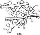
Фиг.1 представляет собой схематический вид в перспективе секции пористого нетканого полотна в соответствии с настоящим изобретением.Figure 1 is a schematic perspective view of a section of a porous non-woven fabric in accordance with the present invention.
Фиг.2 представляет собой схематический вид в перспективе в поперечном сечении одного иллюстративного фильтрующего элемента, использующего пористое нетканое полотно, имеющее трехмерную деформацию.Figure 2 is a schematic perspective view in cross section of one illustrative filter element using a porous non-woven fabric having three-dimensional deformation.
Фиг.3 представляет собой схематический вид в перспективе в поперечном сечении другого иллюстративного фильтрующего элемента, содержащего пористое нетканое полотно, имеющее трехмерную деформацию.Figure 3 is a schematic perspective view in cross section of another illustrative filter element containing a porous non-woven fabric having three-dimensional deformation.
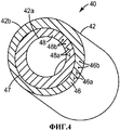
Фиг.4 представляет собой схематический вид в перспективе в поперечном сечении другого иллюстративного фильтрующего элемента, содержащего пористое нетканое полотно, имеющее трехмерную деформацию.4 is a schematic perspective view in cross section of another illustrative filter element comprising a porous non-woven fabric having three-dimensional deformation.
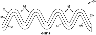
Фиг.5 представляет собой схематический вид в поперечном сечении еще одного иллюстративного фильтрующего элемента, содержащего пористое нетканое полотно, имеющее две или более трехмерных деформаций.FIG. 5 is a schematic cross-sectional view of yet another illustrative filter element comprising a porous non-woven fabric having two or more three-dimensional deformations.
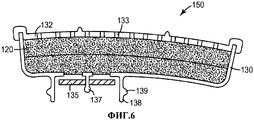
Фиг.6 представляет собой схематический вид в поперечном сечении иллюстративного фильтрующего элемента в соответствии с настоящим изобретением, который расположен в картридже.6 is a schematic cross-sectional view of an illustrative filter element in accordance with the present invention, which is located in the cartridge.
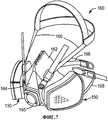
Фиг.7 представляет собой вид в перспективе иллюстративной системы защиты дыхательных путей, использующей фильтрующий элемент, показанный на Фиг.6.FIG. 7 is a perspective view of an exemplary airway protection system using the filter element shown in FIG. 6.
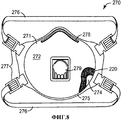
Фиг.8 представляет собой вид в перспективе, частично срезанный, одноразового устройства защиты дыхательных путей, использующего иллюстративный фильтрующий элемент в соответствии с настоящим изобретением, показанный на Фиг.3.FIG. 8 is a perspective view, partially cut away, of a disposable airway protection device using the exemplary filter element of the present invention shown in FIG. 3.
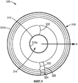
Фиг.9 представляет собой вид в поперечном сечении радиальной фильтрующей системы, такой, как приемлемые для применения в системах коллективной защиты, использующие иллюстративный фильтрующий элемент в соответствии с настоящим изобретением, показанный на Фиг.4.FIG. 9 is a cross-sectional view of a radial filter system, such as those suitable for use in collective protection systems using the exemplary filter element in accordance with the present invention shown in FIG. 4.
Фиг.10 иллюстрирует иллюстративный способ получения пористых нетканых полотен, имеющих трехмерную деформацию, в соответствии с настоящим изобретением.10 illustrates an illustrative method for producing porous non-woven webs having three-dimensional deformation, in accordance with the present invention.
Фигуры необязательно масштабировать. Аналогичные номера, которые используют на фигурах, относятся к аналогичным компонентам. Использование номера относится к компоненту на данной фигуре, однако, оно не предназначено для ограничения компонента на другой фигуре, имеющего тот же номер.Shapes do not have to be scaled. Similar numbers that are used in the figures relate to similar components. The use of a number refers to a component in a given figure, however, it is not intended to limit a component in another figure having the same number.
Подробное описание изобретенияDETAILED DESCRIPTION OF THE INVENTION
В приведенном в данной заявке описании сделаны ссылки на чертежи, которые прилагаются, которые образуют часть данной заявки и которые приведены для иллюстрации нескольких конкретных осуществлений. Должно быть понятно, что другие осуществления входят в настоящее изобретение и могут быть произведены, не выходя за объем или суть настоящего изобретения. Приведенное ниже подробное описание, поэтому, не должно быть воспринято как ограничивающее.In the description given in this application, reference is made to the drawings, which are attached, which form part of this application and which are given to illustrate several specific implementations. It should be clear that other implementations are included in the present invention and can be produced without departing from the scope or essence of the present invention. The detailed description below, therefore, should not be construed as limiting.
Все научные и технические термины, используемые в данной заявке, имеют значения, традиционно используемые в данной области техники, если не указано иное. Если не указано иное, все числа, выражающие размеры параметров, количества и физические свойства, которые используют в данном описании и формуле изобретения, должны подразумеваться как модифицированные во всех случаях под термином «приблизительно». Соответственно, если не указано иное, численные параметры, приведенные в приведенном ниже описании и формуле изобретения, которая прилагается, являются приближениями, которые могут варьироваться в зависимости от желаемых свойств, рассмотренных как такие, которые должны быть получены специалистом в данной области техники, применяя доктрины, описанные в данной заявке.All scientific and technical terms used in this application have the meanings traditionally used in this technical field, unless otherwise indicated. Unless otherwise specified, all numbers expressing the dimensions of the parameters, quantities and physical properties that are used in this description and the claims should be understood as modified in all cases by the term "approximately". Accordingly, unless otherwise indicated, the numerical parameters given in the description below and the claims that are attached are approximations that may vary depending on the desired properties, considered as those that should be obtained by a person skilled in the art, using doctrines described in this application.
Указание численных диапазонов при помощи конечных точек включает все числа, подпадающие в данный диапазон (например, от 1 до 5 включает 1, 1,5, 2, 2,75, 3, 3,80, 4 и 5) и любой диапазон в данном диапазоне.Specifying numerical ranges using endpoints includes all numbers falling within this range (for example, from 1 to 5 includes 1, 1.5, 2, 2.75, 3, 3.80, 4 and 5) and any range in this range.
Как используют в данном описании и формуле изобретения, которая прилагается, форма единственного числа охватывает осуществления, имеющие множественные ссылки, если из контекста четко не следует иное. Как используют в данном описании и формуле изобретения, которая прилагается, термин «или» в общем, применяют в его смысле, включая «и/или», если из контекста четко не следует иное.As used in this description and the claims that are attached, the singular form encompasses implementations having multiple references, unless the context clearly indicates otherwise. As used in this description and the claims that are attached, the term “or” is generally used in its sense, including “and / or”, unless the context clearly indicates otherwise.
Иллюстративные осуществления настоящего изобретения используют два или более слоев пористых нетканых полотен, где, по меньшей мере, два слоя содержат термопластичные эластомерные полимерные волокна и активные частицы, впутанные в волокнах. Полотна в соответствии с настоящим изобретением характеризуются трехмерной формой или деформацией, которая может быть придана волокну, например, при помощи процесса формования.Illustrative implementations of the present invention use two or more layers of porous non-woven webs, where at least two layers contain thermoplastic elastomeric polymer fibers and active particles entangled in the fibers. The canvases in accordance with the present invention are characterized by a three-dimensional shape or deformation, which can be imparted to the fiber, for example, using the molding process.
Как ожидают, данная заявка облегчает получение формованных фильтрующих элементов, включая фильтрующие элементы, которые могут быть применены в устройствах защиты дыхательных путей, с эксплуатационными и конструкционными признаками, которых тяжело достичь при помощи существующих технологий. Первичная существующая технология получения формованных фильтрующих элементов, склеенных смолой частиц углерода, включает комбинирование мелкоизмельченных частиц смолы с частицами углерода с последующим их формованием под воздействием тепла и давления. Такие содержащие углерод формы часто используют в фильтрующих слоях. Однако такая существующая технология имеет различные недостатки. Например, измельчение смолы в мелкие частицы для применения в процессе склеивания частиц смолой имеет тенденцию к тому, чтобы быть относительно дорогой процедурой. Дополнительно, процесс склеивания смолой имеет тенденцию к тому, чтобы закупоривать поверхность углерода, таким образом, уменьшая активность углерода. Дополнительно, очень сложно разделить на слои массы частиц, склеенных смолой.As expected, this application facilitates the production of molded filter elements, including filter elements that can be used in airway protection devices, with operational and structural features that are difficult to achieve with existing technologies. The primary existing technology for producing molded filter elements glued together with carbon particles of resin involves combining finely divided resin particles with carbon particles, followed by their molding under the influence of heat and pressure. Such carbon-containing forms are often used in filter layers. However, such existing technology has various disadvantages. For example, grinding the resin into fine particles for use in a resin bonding process tends to be a relatively expensive procedure. Additionally, the resin bonding process tends to clog the carbon surface, thereby reducing carbon activity. Additionally, it is very difficult to separate into layers the masses of particles adhered by resin.
Наоборот, иллюстративные фильтрующие элементы в соответствии с настоящим изобретением, как ожидают, имеют более низкий перепад давления ввиду использования волокон вместо склеивающей смолы, более низкие затраты при обработке и гораздо более высокое сохранение активности углерода. Другие преимущества осуществлений настоящего изобретения включают обеспечение альтернативы фильтрующему слою, который получают с использованием процесса ливневого наполнения, и способность получения сложных форм фильтрующих элементов, чего сложно достичь при помощи традиционных набивок фильтров. Дополнительно, иллюстративные осуществления настоящего изобретения обеспечивают преимущественный способ комбинирования множественных слоев полотен, содержащих углерод, в фильтрующий слой. Множественные слои могут включать толстые слои с очень большими частицами для емкости, тонкие «полирующие» слои с меньшими частицами, или слои, обработанные различными материалами для достижения широкого диапазона фильтрующих эксплуатационных свойств.Conversely, the exemplary filter elements in accordance with the present invention are expected to have a lower pressure drop due to the use of fibers instead of an adhesive resin, lower processing costs and a much higher conservation of carbon activity. Other advantages of the embodiments of the present invention include providing an alternative to the filter layer that is obtained using the storm filling process, and the ability to produce complex shapes of filter elements, which is difficult to achieve with traditional filter packings. Additionally, exemplary embodiments of the present invention provide an advantageous method of combining multiple layers of carbon-containing webs into a filter layer. Multiple layers may include thick layers with very large particles for the container, thin “polishing” layers with smaller particles, or layers treated with different materials to achieve a wide range of filtering performance.
На Фиг.1 схематично показана секция пористого нетканого полотна 10, приемлемого для применения в иллюстративных осуществлениях настоящего изобретения. Как используют в данной заявке, слово «пористый» относится к изделию, которое является достаточно проницаемым для газов таким образом, чтобы его можно было использовать в фильтрующем элементе устройства защиты дыхательных путей. Фраза «нетканое полотно» относится к волокнистому полотну, характеризующемуся запутанностью или точечным соединением волокон. Пористое нетканое полотно 10 содержит активные частицы 12a, 12b, 12c, расположенные, например, впутанные, в полимерных волокнах 14a, 14b, 14c. Небольшие соединенные поры, образованные в нетканом полотне 10 (например, между полимерными волокнами и частицами), пропускают окружающий воздух, или другие текучие среды проходят через нетканое полотно 10. Активные частицы, например, 12a, 12b, 12c, могут быть способными к поглощению растворителей и других потенциально опасных веществ, присутствующих в таких текучих средах. Слово «впутанные» при использовании в отношении частиц в нетканом полотне относится к частицам, которые в достаточной степени связаны или уловлены полотном таким образом, чтобы оставаться внутри или на полотне, если полотно подвергают осторожному обращению, такому, как драпировка полотна над горизонтальным стержнем. Примеры приемлемых нетканых полотен и способы их получения описаны, например, в публикации патентной заявки США №US 2006/0096911.Figure 1 schematically shows a section of a porous
Примеры активных частиц, приемлемых для применения в некоторых осуществлениях настоящего изобретения, включают сорбенты, катализаторы и химически реакционно-способные вещества. Может быть применено множество активных частиц. В некоторых осуществлениях, активные частицы будут способны поглощать или адсорбировать газы, аэрозоли или текучие среды, которые, как ожидают, будут присутствовать в условиях целевого применения. Активные частицы могут иметь любую применимую форму, включая шарики, хлопья, гранулы или агломераты. Предпочтительные активные частицы включают активированный уголь; окись алюминия и другие оксиды металлов; бикарбонат натрия; частицы металлов (например, частицы серебра), которые могут удалять компонент из текучей среды путем адсорбции, химической реакции или амальгамирования; каталитические агенты на основе частиц, такие как гопкалит или наноразмерные частицы золота (которые могут катализировать окисление моноксида углерода); глину и другие минералы, обработанные кислотными растворами, такими, как уксусная кислота, или щелочными растворами, такими, как водный гидроксид натрия; ионно-обменные смолы, молекулярные сита и другие цеолиты; кремнезем; биоциды; фунгициды и вируциды. Активированный уголь и окись алюминия являются особо предпочтительными активными частицами.Examples of active particles suitable for use in some embodiments of the present invention include sorbents, catalysts, and chemically reactive substances. Many active particles can be used. In some implementations, the active particles will be able to absorb or adsorb gases, aerosols, or fluids that are expected to be present under the conditions of the intended use. The active particles may be of any suitable form, including beads, flakes, granules or agglomerates. Preferred active particles include activated carbon; aluminum oxide and other metal oxides; bicarbonate of soda; metal particles (e.g. silver particles) that can remove a component from the fluid by adsorption, chemical reaction or amalgamation; particle-based catalytic agents, such as hopcalite or nano-sized gold particles (which can catalyze the oxidation of carbon monoxide); clay and other minerals treated with acidic solutions, such as acetic acid, or alkaline solutions, such as aqueous sodium hydroxide; ion exchange resins, molecular sieves and other zeolites; silica; biocides; fungicides and viricides. Activated carbon and alumina are particularly preferred active particles.
Иллюстративные каталитические материалы включают Carulite 300 (также имеет название гопкалит, комбинация оксида меди и диоксида марганца (из MSDS)), который удаляет моноксид углерода (CO), или катализатор, содержащий наноразмерные частицы золота, такой, как гранулированный активированный уголь, покрытый диоксидом титана и наноразмерными частицами золота, расположенными на слое диоксида титана (патентная заявка США №2004/0095189 A1), который удаляет CO, OV и другие соединения.Illustrative catalytic materials include Carulite 300 (also called hopcalite, a combination of copper oxide and manganese dioxide (from MSDS)), which removes carbon monoxide (CO), or a catalyst containing nanoscale particles of gold, such as granular activated carbon coated with titanium dioxide and nano-sized gold particles located on a layer of titanium dioxide (US patent application No. 2004/0095189 A1), which removes CO, OV and other compounds.
Иллюстративные химически реакционно-способные соединения включают триэтилендиамин, гопкалит, хлорид цинка, окись алюминия (для фтороводорода), цеолиты, карбонат кальция и газопромыватели на основе диоксида углерода (например, гидроксид лития). Любое одно или более из таких химически реакционно-способных веществ могут находиться в форме частиц или подложкой для них могут быть частицы, типично с большими площадями поверхностей, такие как частицы активированного угля, окиси алюминия или цеолита.Illustrative chemically reactive compounds include triethylenediamine, hopcalite, zinc chloride, alumina (for hydrogen fluoride), zeolites, calcium carbonate, and carbon dioxide scrubbers (e.g., lithium hydroxide). Any one or more of these chemically reactive substances may be in the form of particles or the substrate for them may be particles, typically with large surface areas, such as particles of activated carbon, alumina or zeolite.
Более чем один тип активных частиц может быть использован в том же самом иллюстративном пористом нетканом полотне в соответствии с настоящим изобретением. Например, могут быть применены смеси активных частиц, например, для поглощения смесей газов. Желаемый размер активных частиц может значительно варьироваться и обычно будет выбран, исходя, частично, из целевых условий обслуживания. Как общее правило, активные частицы могут иметь различные размеры средних диаметров от приблизительно 5 до 3000 микрометров. Предпочтительно активные частицы имеют средний диаметр менее чем приблизительно 1500 микрометров, более предпочтительно имеют средний диаметр от приблизительно 30 до приблизительно 800 микрометров, и наиболее предпочтительно имеют средний диаметр от приблизительно 100 до приблизительно 300 микрометров. Смеси (например, бимодальные смеси) активных частиц, имеющих различные диапазоны размеров, могут быть также применены. В некоторых осуществлениях настоящего изобретения, более чем 60 массовых процентов активных частиц впутаны в полотно. В других осуществлениях, предпочтительно, по меньшей мере 80 массовых процентов активных частиц, более предпочтительно по меньшей мере 84 массовых процента и наиболее предпочтительно по меньшей мере 90 массовых процентов активных частиц впутаны в полотно.More than one type of active particles can be used in the same illustrative porous non-woven fabric in accordance with the present invention. For example, mixtures of active particles can be used, for example, to absorb gas mixtures. The desired size of the active particles can vary significantly and will usually be selected based, in part, on the target service conditions. As a general rule, active particles can have different sizes of average diameters from about 5 to 3000 micrometers. Preferably, the active particles have an average diameter of less than about 1500 micrometers, more preferably have an average diameter of from about 30 to about 800 micrometers, and most preferably have an average diameter of from about 100 to about 300 micrometers. Mixtures (e.g., bimodal mixtures) of active particles having different size ranges can also be used. In some implementations of the present invention, more than 60 weight percent of the active particles are entangled in the web. In other implementations, preferably at least 80 weight percent of the active particles, more preferably at least 84 weight percent and most preferably at least 90 weight percent of the active particles are woven into the web.
Примеры полимерных волокон, приемлемых для применения в некоторых осуществлениях настоящего изобретения, включают термопластичные полимерные волокна и, предпочтительно, термопластичные эластомерные полимерные волокна. Множество волокнообразующих полимерных веществ могут быть приемлемым образом применены, включая термопластичные вещества, такие как полиуретановые эластомерные материалы (например, доступные под торговыми названиями IROGRAN™ от Huntsman LLC и ESTANE™ от Noveon, Inc.), термопластичные эластомерные полиолефины (такие как полиолефиновые термопластичные эластомеры, доступные от ExxonMobil под торговым названием Vistamaxx), полибутиленовые эластомерные материалы (например, доступные под торговым названием CRASTIN™ от Е.I.DuPont de Nemours & Co.), сложно-полиэфирные эластомерные материалы (например, доступные под торговым названием HYTREL™ от Е.I.DuPont de Nemours & Co.), эластомерные материалы на основе блок-сополимеров полиамидов и простых эфиров (например, доступные под торговым названием РЕВАХ™ от Atofina Chemicals, Inc.) и эластомерные стироловые блок-сополимеры (например, доступные под торговыми названиями KRATON™ от Kraton Polymers и SOLPRENE™ от Dynasol Elastomers).Examples of polymer fibers suitable for use in some embodiments of the present invention include thermoplastic polymer fibers and, preferably, thermoplastic elastomeric polymer fibers. Many fiber-forming polymeric substances can be suitably applied, including thermoplastic substances such as polyurethane elastomeric materials (for example, available under the trade names IROGRAN ™ from Huntsman LLC and ESTANE ™ from Noveon, Inc.), thermoplastic elastomeric polyolefins (such as polyolefin thermoplastic elastomers available from ExxonMobil under the trade name Vistamaxx), polybutylene elastomeric materials (for example, available under the trade name CRASTIN ™ from E.I. DuPont de Nemours & Co.), polyester elastomers materials (for example, available under the trade name HYTREL ™ from E.I. DuPont de Nemours & Co.), elastomeric materials based on block copolymers of polyamides and ethers (for example, available under the trade name REVAH ™ from Atofina Chemicals, Inc.) and elastomeric styrene block copolymers (for example, available under the trade names KRATON ™ from Kraton Polymers and SOLPRENE ™ from Dynasol Elastomers).
Некоторые полимеры могут быть растянуты до гораздо более чем 125 процентов их изначальной релаксационной длины и многие из них будут восстановлены по существу до их изначальной релаксационной длины после высвобождения сил смещения, и этот последний класс веществ является, в общем, предпочтительным. Термопластичные полиуретаны, эластомерные полиолефины, полибутилены и стирольные блок-сополимеры являются в особенности предпочтительными. При желании, часть полотна может представлять собой другие волокна, не имеющие указанной эластичности или сжатия при кристаллизации, например, волокна традиционных полимеров, таких как полиэтилен терефталат; многокомпонентные волокна (например, двухкомпонентные волокна с оболочкой из второго волокна, разделяемые или параллельные двухкомпонентные волокна и так называемые волокна типа «островки в море»); штапельные волокна (например, из природных или синтетических материалов) и т.п. Предпочтительно, однако, применяют относительно малые количества таких других волокон таким образом, чтобы не уменьшать ненадлежащим образом желаемый уровень нагрузки сорбента и свойства готового полотна.Some polymers can be stretched to much more than 125 percent of their original relaxation length and many of them will be restored essentially to their original relaxation length after the release of bias forces, and this latter class of substances is generally preferred. Thermoplastic polyurethanes, elastomeric polyolefins, polybutylenes and styrene block copolymers are particularly preferred. If desired, part of the web may be other fibers that do not have the specified elasticity or compression during crystallization, for example, fibers of traditional polymers such as polyethylene terephthalate; multicomponent fibers (for example, two-component fibers with a sheath of a second fiber, separable or parallel two-component fibers, and so-called “islands in the sea” type fibers); staple fibers (for example, from natural or synthetic materials), etc. Preferably, however, relatively small amounts of such other fibers are used in such a way as not to improperly reduce the desired level of sorbent load and the properties of the finished web.
Фиг.2 представляет собой схематический вид в перспективе в поперечном сечении одного иллюстративного фильтрующего элемента 20, использующего пористое нетканое полотно 22. Полотно 22 содержит два или более слоев, таких как первый и второй слои 26 и 28, каждый из которых или оба могут быть пористым нетканым полотном 10, таким как показано на Фиг.1. В одном иллюстративном осуществлении, первый слой полотна 26 содержит первые активные частицы 26а, впутанные в первых полимерных волокнах 26b, и второй слой полотна 28 содержит вторые активные частицы 28а, впутанные во вторых полимерных волокнах 28b.Figure 2 is a schematic perspective view in cross section of one illustrative filter element 20 using a porous non-woven fabric 22. The canvas 22 contains two or more layers, such as the first and second layers 26 and 28, each of which or both can be porous
Различные комбинации материалов первых активных частиц 26а, первых полимерных волокон 26b, вторых активных частиц 28а и вторых полимерных волокон 28b могут быть применены в иллюстративных осуществлениях настоящего изобретения. Одно иллюстративное осуществление представляет собой фильтрующий элемент, в котором первый слой 26 разработан для фильтрования большей части целевого загрязняющего вещества (такого, как газ), в то время как второй слой 28 разработан для удаления небольших количеств целевого загрязняющего вещества, которое проходит через первый слой 26. В таких иллюстративных осуществлениях, первый слой будет типично содержать большие (например, от 12×20 до 6×12) частицы сорбента. Второй слой будет типично содержать меньшие частицы сорбента или катализатора (например, от 80×325 до 60×140).Various combinations of materials of the first active particles 26a, the first polymer fibers 26b, the second active particles 28a and the second polymer fibers 28b can be used in illustrative embodiments of the present invention. One illustrative implementation is a filter element in which the first layer 26 is designed to filter most of the target pollutant (such as gas), while the second layer 28 is designed to remove small amounts of the target pollutant that passes through the first layer 26 In such illustrative embodiments, the first layer will typically contain large (eg, 12 × 20 to 6 × 12) sorbent particles. The second layer will typically contain smaller particles of sorbent or catalyst (for example, from 80 × 325 to 60 × 140).
Другое иллюстративное осуществление представляет собой фильтрующий элемент, в котором первый слой 26 и второй слой 28 оба разработаны для обеспечения первичной фильтрующей функции для одного компонента многокомпонентной фильтрующей системы. В таких иллюстративных осуществлениях, первый слой 26 может содержать соответствующий сорбент и/или каталитические активные частицы для удаления одного компонента из газового потока, в то время как второй (и/или третий, четвертый, и т.д.) слой 28 будет содержать соответствующие активные частицы для удаления второго компонента из газового потока. Например, может быть желаемым разработать фильтрующий элемент, который сможет фильтровать оба кислотного и основного газов. В таком случае, первый слой 26 может содержать активные частицы для удаления кислотных газов, в то время как второй слой 28 может содержать активные частицы для удаления основных газов. Оба типа активных частиц могут быть частицами активированного угля, которые обрабатывают кислотные или основные газы.Another exemplary embodiment is a filter element in which the first layer 26 and the second layer 28 are both designed to provide a primary filter function for one component of a multicomponent filter system. In such illustrative implementations, the first layer 26 may contain a suitable sorbent and / or catalytic active particles to remove one component from the gas stream, while the second (and / or third, fourth, etc.) layer 28 will contain the corresponding active particles to remove the second component from the gas stream. For example, it may be desirable to develop a filter element that can filter both acid and base gases. In this case, the first layer 26 may contain active particles for removal of acid gases, while the second layer 28 may contain active particles for removal of basic gases. Both types of active particles can be activated carbon particles that process acidic or basic gases.
В других иллюстративных осуществлениях, фильтрующий элемент может содержать комбинации указанных выше конструкций. Иллюстративные осуществления могут содержать множественные наборы слоев больших частиц/малых частиц, каждый из которых разработан для фильтрования различных компонентов газового потока. Вещества, используемые для первых полимерных волокон 26b и вторых полимерных волокон 28b, могут быть одинаковыми или разными. В одном иллюстративном осуществлении, первый и второй слои оба могут содержать одинаковый тип выдувных микроволокон, содержащих те же самые вещества.In other illustrative embodiments, the filter element may comprise combinations of the above structures. Illustrative implementations may include multiple sets of layers of large particles / small particles, each of which is designed to filter various components of the gas stream. The substances used for the first polymer fibers 26b and the second polymer fibers 28b may be the same or different. In one illustrative implementation, the first and second layers both may contain the same type of blown microfibers containing the same substances.
Обращаясь дополнительно к Фиг.2, полотно 22 имеет трехмерную деформацию 24, которая проиллюстрирована в поперечном сечении. В особенности, скорее, чем планарную конфигурацию, в которой большинство поверхностей 22а и 22b полотна 22 будут иметь планарные конфигурации и будут, в общем, параллельны одна другой, что может быть в случае типичных нетканых полотен, содержащих частицы, полотно 22 сформировано, например, по меньшей мере, таким образом, что одна из его основных поверхностей 22а и 22b отклоняется от планарной конфигурации. В данном иллюстративном осуществлении первая поверхность 22а смещена от планарной конфигурации на Da, в то время как вторая поверхность 22а смещена от планарной конфигурации на Db. Предпочтительно, первый слой 26 является соприкасающимся со вторым слоем 28 по деформации, как показано на Фиг.2. Как показано на Фиг.2, первый и второй слои 26 и 28 размещены непосредственно прилегающими друг к другу. Дополнительно, первый и второй слои 26 и 28 находятся в фактическом контакте (без каких-либо воздушных промежутков или промежуточных слоев) вдоль границы 27.Turning further to FIG. 2, the web 22 has a three-dimensional deformation 24, which is illustrated in cross section. In particular, rather than a planar configuration in which most of the surfaces 22a and 22b of the web 22 will have planar configurations and will be generally parallel to one another, which may be the case with typical non-woven webs containing particles, the web 22 is formed, for example, at least in such a way that one of its main surfaces 22a and 22b deviates from the planar configuration. In this illustrative embodiment, the first surface 22a is offset from the planar configuration by Da, while the second surface 22a is offset from the planar configuration by Db. Preferably, the first layer 26 is in contact with the second layer 28 in deformation, as shown in FIG. As shown in FIG. 2, the first and second layers 26 and 28 are placed immediately adjacent to each other. Additionally, the first and second layers 26 and 28 are in actual contact (without any air gaps or intermediate layers) along the boundary 27.
Полотно 22 дополнительно характеризуется толщиной полотна Т, которая может быть определена как расстояние между первой поверхностью 22а и второй поверхностью 22b. Некоторые иллюстративные размеры деформаций в соответствии с иллюстративными осуществлениями настоящего изобретения включают толщину Т, составляющую от 5 до 10 мм или более. Значение Т будет зависеть от целевого назначения фильтрующего элемента и других соображений. Деформация 24 дополнительно характеризуется линейной длиной L, которая может быть определена как длина выступа в планарную поверхность под деформацией 24 поперечного сечения деформации 24 в плоскости, которая включает смещение Da. В некоторых иллюстративных осуществлениях, по меньшей мере, один из Da и Db составляет по меньшей мере 0,5 толщины полотна Т в месте полотна, в котором измеряют смещение. В показанном иллюстративном осуществлении, толщину Т и смещение Da оба измеряют в месте 23. В других иллюстративных осуществлениях, по меньшей мере, один из Da и Db могут в, по меньшей мере, 1-10, 2-10, 4-10, 5-10 или более чем в 10 раз превышать толщину полотна Т в месте полотна, в котором измеряют смещение, в зависимости от целевого использования фильтрующего элемента или других соображений.The web 22 is further characterized by a web thickness T, which can be defined as the distance between the first surface 22a and the second surface 22b. Some exemplary strain sizes in accordance with exemplary embodiments of the present invention include a thickness T of 5 to 10 mm or more. The value of T will depend on the purpose of the filter element and other considerations. The deformation 24 is additionally characterized by a linear length L, which can be defined as the length of the protrusion into the planar surface under the deformation 24 of the cross section of the deformation 24 in a plane that includes the displacement Da. In some illustrative embodiments, at least one of Da and Db is at least 0.5 of the web thickness T at the site of the web at which the displacement is measured. In the exemplary embodiment shown, the thickness T and the offset Da are both measured at location 23. In other exemplary embodiments, at least one of Da and Db can be in at least 1-10, 2-10, 4-10, 5 -10 or more than 10 times the thickness of the web T at the location of the web at which the displacement is measured, depending on the intended use of the filter element or other considerations.
Обращаясь дополнительно к Фиг.2, основная поверхность 22а полотна 22 иллюстративного фильтрующего элемента 20 может быть охарактеризована как вогнутая поверхность, в то время как основная поверхность 22b может быть охарактеризована как выпуклая поверхность. В некоторых таких иллюстративных осуществлениях, вогнутая поверхность 22а характеризуется отклонением Da от планарной конфигурации, которое составляет, по меньшей мере, 0,5 толщины полотна Т в месте полотна, где измеряют смещение. В других иллюстративных осуществлениях, Da поверхности 22а может в, по меньшей мере, 1-10, 2-10, 4-10, 5-10, или более чем в 10 раз превышать толщину полотна Т в месте полотна, где измеряют смещение, в зависимости от целевого назначения фильтрующего элемента или других соображений.Turning further to FIG. 2, the main surface 22a of the web 22 of the illustrative filter element 20 can be characterized as a concave surface, while the main surface 22b can be described as a convex surface. In some such illustrative implementations, the concave surface 22a is characterized by a deviation Da from the planar configuration, which is at least 0.5 thickness of the web T at the location of the web where the displacement is measured. In other illustrative embodiments, Da of the surface 22a may be at least 1-10, 2-10, 4-10, 5-10, or more than 10 times the thickness of the web T at the location of the web where the displacement is measured, in depending on the purpose of the filter element or other considerations.
В некоторых типичных иллюстративных осуществлениях, длина линейной деформации L может в, по меньшей мере, 3-4, или 3-5 раз превышать толщину Т. В других иллюстративных осуществлениях, длина линейной деформации L может превышать ее в, по меньшей мере, 10-50, 20-50, 30 или более, 40 или более, или 50 или более раз. Некоторые иллюстративные абсолютные значения L включают 2 см, 4 см или 10 см или более. Значение L и его соотношение с Т будут зависеть от различных факторов, включая целевое применение фильтрующего элемента. Специалисты в данной области техники смогут легко оценить, что деформации полотна 22 могут иметь любую другую приемлемую форму и размер, включая, но не ограничиваясь приведенным, показанные на Фиг.3-4.In some typical illustrative implementations, the linear strain length L may be at least 3-4, or 3-5 times greater than the thickness T. In other illustrative embodiments, the linear strain length L may exceed it by at least 10- 50, 20-50, 30 or more, 40 or more, or 50 or more times. Some illustrative absolute values of L include 2 cm, 4 cm, or 10 cm or more. The value of L and its relationship with T will depend on various factors, including the intended use of the filter element. Those skilled in the art will be able to easily appreciate that the deformations of the web 22 may have any other acceptable shape and size, including but not limited to those shown in FIGS. 3-4.
В некоторых иллюстративных осуществлениях настоящего изобретения, полотно 22 может быть сохраняющим форму. В контексте настоящего изобретения, термин «сохраняющий форму,» в отношении к изделию, означает, что изделие имеет достаточную эластичность и структурную целостность таким образом, чтобы (i) сопротивляться деформации при применении силы или (ii) уступать деформирующей силе, но затем по существу возвращать исходную форму после устранения деформирующей силы, где количество и тип деформирующей силы являются типичными в обычных условиях, в которых предполагают использовать изделие. В некоторых иллюстративных осуществлениях настоящего изобретения, полотно 22 может быть самоподдерживающимся. Термин «самоподдерживающийся», в отношении к изделию, означает, что изделие обладает достаточной жесткостью для того, чтобы быть способным к сохранению непланарной конфигурации самой по себе, то есть, при отсутствии любых дополнительных поддерживающих слоев или структур.In some illustrative embodiments of the present invention, the web 22 may be shape retaining. In the context of the present invention, the term “shape retaining,” as applied to the product, means that the product has sufficient elasticity and structural integrity so as to (i) resist deformation when a force is applied or (ii) give way to a deforming force, but then essentially return to its original form after eliminating the deforming force, where the amount and type of deforming force are typical in ordinary conditions in which it is intended to use the product. In some illustrative implementations of the present invention, the web 22 may be self-sustaining. The term "self-supporting", in relation to the product, means that the product has sufficient rigidity to be able to maintain the non-planar configuration by itself, that is, in the absence of any additional supporting layers or structures.
Фиг.3 представляет собой схематический вид в перспективе в поперечном сечении другого иллюстративного фильтрующего элемента 30, использующего пористое нетканое полотно 32. Полотно 32 содержит два или более слоев, таких как первый и второй слои 36 и 38, каждый из которых или оба могут быть пористым нетканым полотном 10, как показано на Фиг.1. В одном иллюстративном осуществлении, первый слой полотна 36 содержит первые активные частицы 36а, впутанные в первых полимерных волокнах 36b, и второй слой полотна 38 содержит вторые активные частицы 38а, впутанные во вторых полимерных волокнах 38b.Figure 3 is a schematic perspective view in cross section of another
Полотно 32 имеет трехмерную деформацию 34. Предпочтительно, первый слой 36 является соприкасающимся со вторым слоем 38 по деформации, как показано на Фиг.3. В данном иллюстративном осуществлении, первая поверхность 32а смещена от планарной конфигурации на Da', в то время как вторая поверхность 32а смещена от планарной конфигурации на Db'. Полотно 32 дополнительно характеризуется вариабельной толщиной полотна T1, Т2, Т3 и Т4, каждая из которых определена как расстояние между первой поверхностью 32а и второй поверхностью 32b. Деформация 34 дополнительно характеризуется линейной длиной линии L'. L' является выступом поперечного сечения деформации 34, в плоскости, содержащей смещение Da′, в планарную поверхность под деформацией 34. В некоторых иллюстративных осуществлениях настоящего изобретения, полотно 32 может быть самоподдерживающимся и/или сохраняющим форму.The
Предпочтительно, в осуществлениях, которые имеют вариабельную толщину полотна, толщина варьируется не более чем в 10 раз по сравнению со средней толщиной Tav, вдоль, по меньшей мере, одного направления по деформации 34. Более предпочтительно, толщина варьируется не более чем в 5 раз по сравнению со средней толщиной Tav, вдоль, по меньшей мере, одного направления по деформации 34, и, даже более предпочтительно, не более чем в 2, 1, и наиболее предпочтительно, не более чем в 0,5 раза. Средняя толщина может быть рассчитана путем выбора конкретного направления по деформации 34, например, вдоль поперечного сечения полотна 32 и деформации 34 плоскости, приведенной на Фиг.3, измерением значений толщин полотна, предпочтительно, для, по меньшей мере, 4 различных мест (например, 1, 2, 3 и 4) вдоль выбранного направления (т.е., значения T1, Т2, Т3 и Т4), и усреднения данных значений следующим образом:Preferably, in embodiments that have a variable web thickness, the thickness varies no more than 10 times as compared with the average thickness Tav along at least one direction of
Tav=(Т1+Т2+Т3+Т4)/4Tav = (T1 + T2 + T3 + T4) / 4
В некоторых иллюстративных осуществлениях, места 1, 2, 3 и 4 могут быть выбраны путем деления L на 5 приблизительно равных частей и измерения толщин в 4 внутренних точках. Некоторые иллюстративные осуществления трехмерной деформации 34 полотна 32 могут быть охарактеризованы градиентом плотности, который имеет относительно низкое значение. В одном иллюстративном осуществлении, трехмерная деформация 34 характеризуется градиентом плотности, составляющим менее чем 20 к 1. В других иллюстративных осуществлениях, трехмерная деформация 34 может быть охарактеризована градиентом плотности, составляющим менее чем 10 к 1, 3 к 1 или 2 к 1.In some illustrative implementations,
Градиент плотности может быть определен следующим образом. Две пробы отбирают из двух различных мест трехмерной деформации 34 полотна 32, таких как любые два места 1, 2, 3 и 4, показанные на Фиг.3. Плотности δ1 и δ2 могут быть затем определены при помощи процедуры, описанной ниже, и градиент плотности δg определяют как соотношение большего значения плотности δ2 и меньшего значения плотности δ1.The density gradient can be determined as follows. Two samples are taken from two different places of three-
Фиг.4 является схематическим видом в перспективе другого иллюстративного фильтрующего элемента 40, использующего пористое нетканое полотно 42. Полотно 42 имеет трехмерную деформацию 44. В данном иллюстративном осуществлении, первая поверхность 42а и вторая поверхность 42b полотна 42 смещены от планарной конфигурации таким образом, что полотно 42 образует, в общем, цилиндрическую форму. Полотно 42 содержит два или более слоев, таких как первый и второй слои 46 и 48, каждый из которых или оба могут быть пористым нетканым полотном 10, как показано на Фиг.1. В одном иллюстративном осуществлении, первый слой полотна 46 содержит первые активные частицы 46а, впутанные в первых полимерных волокнах 46b, и второй слой полотна 48 содержит вторые активные частицы 48а, впутанные во вторых полимерных волокнах 48b. Предпочтительно, первый слой 46 является соприкасающимся со вторым слоем 48 по деформации, как показано на Фиг.4. Такие иллюстративные фильтрующие элементы являются особо преимущественными для применения в устройствах защиты дыхательных путей, разработанных для применения для защиты при проблемах смешанных газов, например, паров аммиака и органических веществ.4 is a schematic perspective view of another
Фиг.5 представляет собой вид в поперечном сечении другого иллюстративного фильтрующего элемента 50, использующего пористое нетканое полотно 52, такое, как полотна, описанные в связи с другими иллюстративными осуществлениями настоящего изобретения. Полотно 52 имеет две или более трехмерные деформации 54. В данном иллюстративном осуществлении, первая поверхность 52а и вторая поверхность 52b полотна 52 смещены от планарной конфигурации таким образом, что полотно 52 образует серии трехмерных деформаций. В показанном осуществлении, деформации 54 образуют линейный массив (деформации 54 образуют повторяющуюся последовательность вдоль одного направления). В других иллюстративных осуществлениях, деформации 54 образуют двухмерный массив (деформации 54 образуют повторяющуюся последовательность вдоль двух различных направлений). В других иллюстративных осуществлениях, деформации 54 могут образовывать любой тип распределения, такой, как рандомизованный массив. Отдельные деформации могут быть аналогичны по размеру и/или форме или они могут отличаться друг от друга. Полотно 52 содержит два или более слоев, таких как первый и второй слои 56 и 58. Предпочтительно, первый слой 56 является соприкасающимся со вторым слоем 58 по деформации, например, вдоль границы 57, как показано на Фиг.5.5 is a cross-sectional view of another
На Фиг.6 показан схематический вид в поперечном сечении другого иллюстративного фильтрующего элемента 150 в соответствии с настоящим изобретением. Иллюстративный фильтрующий элемент 150 содержит корпус 130. Пористое нетканое полотно 120, сконструированное в соответствии с настоящим изобретением, такое, как иллюстративное полотно, показанное на Фиг.2, расположено внутри корпуса 130. Полотно 120 содержит два или более слоев, таких как первый и второй слои 126 и 128, каждый из которых или оба могут быть пористым нетканым полотном, как описано в данной заявке выше. Полотно 32 имеет трехмерную деформацию 34. Предпочтительно, первый слой 36 является соприкасающимся со вторым слоем 38 по деформации, как показано на Фиг.3. Корпус 130 содержит крышку 132 с отверстиями 133. Окружающий воздух заходит в фильтрующий элемент 150 через отверстия 133, проходит через полотно 120 (вследствие чего потенциально опасные вещества в таком окружающем воздухе обрабатываются активными частицами в полотне 120) и выходит в корпус 130 за впускной воздушный клапан 135, смонтированный на опоре 137.6 is a schematic cross-sectional view of another
Втулка 138 и штыкообразный выступ 139 позволяют съемное присоединение фильтрующего элемента 150 к устройству защиты дыхательных путей 160, показанному на Фиг.7. Устройство 160, которое иногда называют респиратор-полумаска, содержит деформируемую маску 162, которая может быть вставлена формованием вокруг относительно тонкого жесткого структурного элемента или вставки 164. Вставка 164 содержит клапан выхода 165 и имеющие вырез штыкообразные отверстия с резьбой (не показаны на Фиг.7) для съемно присоединенных корпусов 130 фильтрующих элементов 150 в боковых участках устройства 160. Регулируемая лента 166 и опоясывающие ленты 168 позволяют надежно носить устройство 160 над носом и ртом пользователя. Дополнительные детали относительно конструкции такого устройства будут знакомы специалистам в данной области техники.A
На Фиг.8 показаны другие иллюстративные устройства защиты дыхательных путей 270, в которых могут быть использованы иллюстративные осуществления настоящего изобретения. Устройство 270 иногда называют одноразовой или не требующей обслуживания маской, и оно, в общем, имеет чашеобразную оболочку или корпус респиратора 271, содержащий внешнее покровное полотно 272, пористое нетканое полотно 220, сконструированное в соответствии с настоящим изобретением, такое, как иллюстративные полотна, показанные на Фиг.2 и 3, и внутреннее покровное полотно 274. Торцевое сварное соединение 275 удерживает эти слои вместе и обеспечивает участок лицевого уплотнения для уменьшения утечки через торец устройства 270. Устройство 270 содержит регулируемые крепления для головы и шеи 276, прикрепленные к устройству 270 выводными планками 277, носовой ремешок 278 и клапан выдоха 279. Дополнительные детали относительно конструкции такого устройства будут знакомы специалистам в данной области техники.FIG. 8 shows other exemplary
На Фиг.9 показано другое иллюстративное устройство защиты дыхательных путей 300, в котором могут быть использованы иллюстративные осуществления настоящего изобретения, в особенности, иллюстративные осуществления, проиллюстрированного на Фиг.4. Устройство 300 иногда называют фильтрующей системой радиальной фильтрации, например, его используют в системах обработки воздуха для коллективной защиты. В проиллюстрированном осуществлении, вход 314 расположен во внутренней периферии 310а корпуса 310. Выход 316, который находится в гидравлическом соединении с входом 314, может быть расположен во внешней периферии 310b корпуса 310. Иллюстративный фильтрующий элемент 320, расположенный внутри внутренней части корпуса, содержит пористое нетканое полотно 322 в соответствии с настоящим изобретением и три слоя пористого нетканого полотна 324 в соответствии с настоящим изобретением.FIG. 9 shows another exemplary
Полотно 322 может содержать вещества, которые отличаются от одного или более слоев полотна 324 и/или оно может иметь фильтрующие свойства, отличающиеся от фильтрующих свойств одного или более слоев полотна 324. В некоторых иллюстративных осуществлениях, слой полотна 324 может содержать вещества, отличные от веществ одного или более других слоев полотна 324, и/или оно может иметь фильтрующие свойства, отличающиеся от фильтрующих свойств одного или более слоев полотна 324. Дополнительный фильтрующий элемент, такой, как фильтрующий элемент 330 на основе частиц, может быть также обеспечен во внутренней части корпуса 310. Фильтрующий элемент на основе частиц предпочтительно обеспечен сверху фильтрующего элемента 320.The
В одном осуществлении, воздух или другая текучая среда проходят во вход 314, расположенный во внутренней периферии корпуса 310. Затем воздух может проходить через каждый из фильтрующих элементов, как показано при помощи стрелки F, пока не пройдет через выход 316. Настоящее изобретение может быть также применено для других систем обработки текучих сред, и осуществления настоящего изобретения могут иметь различные конфигурации и расположения входа 314 и выхода 316. Например, расположения входа и выхода могут быть реверсированы.In one embodiment, air or other fluid passes into an
Фиг.10 иллюстрирует иллюстративный способ и устройство 900 для получения сохраняющих форму самоподдерживающихся нетканых полотен, имеющих трехмерную деформацию, в соответствии с настоящим изобретением. Полотно, содержащее частицы 920, может иметь сначала планарную конфигурацию. Трехмерная деформация в соответствии с настоящим изобретением может быть придана полотну 920, например, путем формования полотна 920 при помощи иллюстративного устройства 900. Устройство 900 содержит первую термостатируемую заливочную форму 904а и вторую термостатируемую заливочную форму 904b. Формы заливочных форм зависят от формы желаемой деформации, которую необходимо придать полотну 902. Поршень пневмопривода 906 может быть использован для контроля движения первой заливочной формы 904а в направлении второй заливочной формы 904b. Каркас 902 поддерживает заливочные формы 904а, 904b и поршень 906.FIG. 10 illustrates an example method and
В иллюстративном способе получения сохраняющих форму самоподдерживающихся нетканых полотен, имеющих трехмерную деформацию, слои полотна 922 и 924 размещают между заливочными формами 904а и 904b, заливочные формы сводят вместе таким образом, что они подвергают слои полотна 922 и 924 сжатию и нагреванию таким образом, что слои полотна 922 и 924 формируют вместе таким образом, чтобы они соприкасались и также образовывали желаемую форму. Температуры заливочных форм 904а и 904b могут быть одинаковыми или различными и, как ожидают, зависят от полимера(полимеров), которые используют в слоях волокна полотна 922 и 924. При использовании термопластичного полиолефинового эластомера бренда ExxonMobil Vistamaxx 2125, ожидают, что рабочие температуры формы будут составлять от 75°C до 250°C и, более предпочтительно, от 95°C до 120°C. Давления, которые прилагают заливочные формы 904а и 904b к слоям полотна 922 и 924, как ожидают, зависят от полимера(полимеров), которые используют в слоях волокна полотна 922 и 924, и они могут также зависеть от типа и количества активных частиц. Например, при использовании смолы бренда ExxonMobil Vistamaxx 2125, рабочие давления, как ожидают, будут составлять от 20 грамм/см2 до 10000 грамм/см2, и более предпочтительно от 300 до 2000 грамм/см2. Иллюстративные времена формования в таких условиях, как ожидают, будут составлять от 2 секунд до 30 минут. В общем, времена формования будут зависеть от температур, давлений и полимеров, и активных частиц.In an exemplary method for producing shape-preserving self-supporting non-woven webs having a three-dimensional deformation, the web layers 922 and 924 are placed between the
Как полагают, процесс формования смягчает и формирует термопластичные эластомерные полимерные волокна полотна, таким образом, что полученное в результате полотно, имеющее трехмерную деформацию желаемой формы, также содержит соприкасающиеся слои, образованные из слоев полотна 922 и 924. Такие соприкасающиеся слои, образованные при помощи иллюстративного процесса настоящего изобретения, более трудно отделять и они участвуют в повышении износостойкости конструкции фильтрующего элемента. Также считают, что процесс формования является эффективным при получении полотен, способных быть самоподдерживающимися и сохраняющими форму. Другие иллюстративные способы могут включать формование слоев полотна 922 и 924 на или в прессе с нагретыми валиками или путем размещения креплений с нагрузками в печи.The molding process is believed to soften and form thermoplastic elastomeric polymer fibers of the web, such that the resulting web having a three-dimensional deformation of the desired shape also contains contact layers formed from
ТЕСТОВЫЕ МЕТОДЫTEST METHODS
Для расчета плотности пробы фильтрующего элемента в соответствии с настоящим изобретением, можно типично начать с получения относительно неповрежденной и целесообразно характеристичной части фильтрующего элемента. Это может быть реализовано, например, путем отрезания части от пробы, которую исследуют, предпочтительно таким образом, что проба содержит, по меньшей мере, часть трехмерной деформации в соответствии с настоящим изобретением. Важно, чтобы часть была достаточно большой во всех измерениях, которые считают «характеристичными.» Более конкретно, проба должна быть больше, чем активные частицы, диспергированные в полотне, и, предпочтительно, по меньшей мере, в 5 раз больше наибольшего размера частицы в полотне, и, более предпочтительно, по меньшей мере, в 100 больше наибольшего размера частицы в полотне.To calculate the sample density of the filter element in accordance with the present invention, one can typically begin by obtaining a relatively intact and expediently characteristic portion of the filter element. This can be realized, for example, by cutting off a portion of the sample to be examined, preferably in such a way that the sample contains at least a portion of the three-dimensional deformation in accordance with the present invention. It is important that the part be large enough in all dimensions that are considered “characteristic.” More specifically, the sample should be larger than the active particles dispersed in the web, and preferably at least 5 times the largest particle size in the web , and, more preferably, at least 100 larger than the largest particle size in the canvas.
Форма пробы может быть выбрана таким образом, чтобы было легко измерить ее размеры и рассчитать объем, такая, как прямоугольная или цилиндрическая. В случае искривленных поверхностей, может быть преимущественным позволить устройству (ножевой штамп), который используют для разрезания пробы, определять диаметр, например, ножевой штамп. Для измерения размеров такой пробы можно использовать ASTM D 1777-96, тестовая опция №5, в качестве направляющего. Размер прижимной лапки должен быть отрегулирован для приспособления к существующему размеру пробы. Желательно не деформировать пробу во время процесса измерения, но в некоторых обстоятельствах может быть приемлемым более высокое давление, чем указанное в опции №5. Поскольку структуры для измерения являются пористыми, то контакт должен быть по всей области, которая является достаточно большой относительно одной активной частицы. После определения объема характеристической части, необходимо взвесить характеристическую часть. Плотность определяют путем деления массы на объем.The shape of the sample can be chosen so that it is easy to measure its size and calculate the volume, such as rectangular or cylindrical. In the case of curved surfaces, it may be advantageous to allow the device (knife stamp), which is used to cut the sample, to determine the diameter, for example, a knife stamp. To measure the size of such a sample, ASTM D 1777-96, test option No. 5, can be used as a guide. The size of the presser foot must be adjusted to fit the existing sample size. It is advisable not to deform the sample during the measurement process, but in some circumstances a higher pressure than specified in option No. 5 may be acceptable. Since the structures for measurement are porous, the contact should be over the entire region, which is sufficiently large relative to one active particle. After determining the volume of the characteristic part, it is necessary to weigh the characteristic part. Density is determined by dividing the mass by volume.
Также возможно охарактеризовать плотность иллюстративных осуществлений настоящего изобретения путем сравнения плотности компонента на основе частиц в нетканом полотне с плотностью «набивки фильтра» из того же самого материала на основе частиц. Это будет включать удаление частиц из известного объема «характеристической части» и взвешивание такой полученной в результате пробы на основе частиц. Такая частица может быть затем погружена в градуированный цилиндр для получения ее объема «набивки фильтра». Из этих данных можно рассчитать «набивную или кажущуюся» плотность путем деления массы на измеренный объем. Однако результат может быть искажен остаточными полимерами, прилипшими к частице.It is also possible to characterize the density of illustrative embodiments of the present invention by comparing the density of a particle-based component in a nonwoven fabric with the density of a “filter pack" of the same particle-based material. This will include removing particles from a known volume of the “characteristic part” and weighing such a resulting particle-based sample. Such a particle can then be immersed in a graduated cylinder to obtain its “filter packing” volume. From this data, the “packed or apparent" density can be calculated by dividing the mass by the measured volume. However, the result may be distorted by residual polymers adhering to the particle.
ПРИМЕРEXAMPLE
Следующие слои собирали и формовали в фильтрующий респиратор с лицевой маской (похожей на чашу) в соответствии со способами настоящего изобретения:The following layers were collected and molded into a filter respirator with a face mask (similar to a bowl) in accordance with the methods of the present invention:
1. Внешняя оболочка: слой нетканого материала - 20% Kosa Со. тип 295 1,5 дюйма резаные, 6 денье полиэфирные штапельные волокна и 80% Kosa Со. тип 254 1,5 дюйма резаные, 4 денье бико-полиэфирные штапельные волокна.1. Outer sheath: a layer of nonwoven material - 20% Kosa Co. type 295 1.5 inches cut, 6 denier polyester staple fibers and 80% Kosa Co. type 254 1.5 inches cut, 4 denier bicopolyester staple fibers.
2. Слой выдувной микроволоконной фильтрующей среды.2. Layer of blown microfiber filter medium.
3. Слой 4000 г/м2 (грамм на квадратный метр) пористого нетканого полотна в соответствии с настоящим изобретением, включая 12×20 органические активированные паром частицы углерода типа GG, доступные от Kuraray, впутанные в термопластичные эластомерные полиолефиновые волокна.3. A layer of 4000 g / m 2 (gram per square meter) of the porous non-woven fabric of the present invention, including 12 × 20 organic steam activated carbon particles of type GG, available from Kuraray, embedded in thermoplastic elastomeric polyolefin fibers.
4. Слой 600 г/м2 пористого нетканого полотна в соответствии с настоящим изобретением, включая 40×140 органические активированные паром частицы углерода, впутанные в термопластичные эластомерные полиолефиновые полимерные волокна.4. A layer of 600 g / m 2 of the porous non-woven fabric in accordance with the present invention, including 40 × 140 organic steam activated carbon particles entangled in thermoplastic elastomeric polyolefin polymer fibers.
5. Слой плотного полученного аэродинамическим способом микроволоконного гладкого нетканого полотна.5. Layer of dense aerodynamically produced microfiber smooth non-woven fabric.
6. Внутренняя оболочка: слой нетканого материала - 20% Kosa Со. тип 295 1,5 дюйма, резаные, 6 денье полиэфирные штапельные волокна и 80% Kosa Со. тип 254 1,5 дюйма, резаные, 4 денье бико-полиэфирные штапельные волокна.6. Inner sheath: a layer of nonwoven material - 20% Kosa Co. type 295 1.5 inches, cut, 6 denier polyester staple fibers and 80% Kosa Co. type 254 1.5 inches, cut, 4 denier bicopolyester staple fibers.
Вышеуказанные слои помещают в формовочное устройство, предназначенное для формования фильтрующих респираторов с лицевой маской. Верхнюю заливочную форму устанавливали при температуре 235°F, в то время как нижнюю заливочную форму устанавливали при температуре 300°F.The above layers are placed in a molding device designed to form filter respirators with a face mask. The upper casting mold was set at 235 ° F, while the lower casting mold was set at 300 ° F.
Перепад давления конструкций респираторов, сформированных таким образом, при измерении при 85 л/мин, составлял от 14,9 мм воды до 33,7 мм воды. При анализе в соответствии с тестовым методом CEN для циклогексана (тестовые условия: 1000 ppm, 30 л/мин, 20°С, 70% относительной влажности, 10 ppm дыхания), формованная конструкция респиратора имела срок годности 40-59 минут. Соответствующий тест CEN описан в Британском стандарте BS EN 141:200 «Respiratory protective devices - Gas filters and combined filters - Requirements, testing, marking.»The pressure drop of the respirator structures formed in this way, when measured at 85 l / min, ranged from 14.9 mm water to 33.7 mm water. When analyzed according to the CEN test method for cyclohexane (test conditions: 1000 ppm, 30 l / min, 20 ° C, 70% relative humidity, 10 ppm respiration), the molded respirator design had a shelf life of 40-59 minutes. The corresponding CEN test is described in British Standard BS EN 141: 200 “Respiratory protective devices - Gas filters and combined filters - Requirements, testing, marking.”
Таким образом, описаны осуществления формованного слоеного нетканого полотна, содержащего частицы. Специалист в данной области техники оценит, что настоящее изобретение может быть реализовано на практике в осуществлениях, отличных от описанных в данной заявке. Например, могут быть использованы более чем два слоя в соответствии с настоящим изобретением. Описанные осуществления представлены для иллюстрации и не являются ограничивающими, и настоящее изобретение ограничено только формулой изобретения, приведенной в данной заявке ниже.Thus, embodiments of a molded puff nonwoven web containing particles are described. One skilled in the art will appreciate that the present invention may be practiced in implementations other than those described herein. For example, more than two layers in accordance with the present invention may be used. The described embodiments are presented for illustration and are not limiting, and the present invention is limited only by the claims given in this application below.
Claims (15)
Applications Claiming Priority (3)
| Application Number | Priority Date | Filing Date | Title |
|---|---|---|---|
| US13875708P | 2008-12-18 | 2008-12-18 | |
| US61/138,757 | 2008-12-18 | ||
| PCT/US2009/066488 WO2010071739A1 (en) | 2008-12-18 | 2009-12-03 | Shaped layered particle-containing nonwoven web |
Publications (1)
| Publication Number | Publication Date |
|---|---|
| RU2469756C1 true RU2469756C1 (en) | 2012-12-20 |
Family
ID=42269112
Family Applications (1)
| Application Number | Title | Priority Date | Filing Date |
|---|---|---|---|
| RU2011123104/12A RU2469756C1 (en) | 2008-12-18 | 2009-12-03 | Moulded layered non-woven fabric containing particles |
Country Status (11)
| Country | Link |
|---|---|
| US (1) | US20110240027A1 (en) |
| EP (1) | EP2370180A4 (en) |
| JP (1) | JP2012512742A (en) |
| KR (1) | KR20110112337A (en) |
| CN (1) | CN102281924B (en) |
| AU (1) | AU2009327443C1 (en) |
| BR (1) | BRPI0918124A2 (en) |
| CA (1) | CA2747388A1 (en) |
| MX (1) | MX2011006362A (en) |
| RU (1) | RU2469756C1 (en) |
| WO (1) | WO2010071739A1 (en) |
Families Citing this family (23)
| Publication number | Priority date | Publication date | Assignee | Title |
|---|---|---|---|---|
| RU2013109813A (en) | 2010-08-16 | 2014-09-27 | Смит Энд Нефью, Инк. | SYSTEMS AND METHODS FOR CHANGING THE BONE SURFACE |
| JP5884136B2 (en) * | 2011-11-30 | 2016-03-15 | 三ツ星ベルト株式会社 | Method for producing filter molded body |
| US11052268B2 (en) | 2013-02-01 | 2021-07-06 | 3M Innovative Properties Company | Respirator negative pressure fit check devices and methods |
| US9517367B2 (en) | 2013-02-01 | 2016-12-13 | 3M Innovative Properties Company | Respiratory mask having a clean air inlet chamber |
| US9950202B2 (en) | 2013-02-01 | 2018-04-24 | 3M Innovative Properties Company | Respirator negative pressure fit check devices and methods |
| EP3036035A2 (en) * | 2013-08-21 | 2016-06-29 | 3M Innovative Properties Company | Layered or mixed sorbent bed protective filtration device |
| KR20160074460A (en) * | 2013-08-21 | 2016-06-28 | 쓰리엠 이노베이티브 프로퍼티즈 캄파니 | Layered or mixed sorbent bed protective filtration device |
| CA2921844A1 (en) * | 2013-08-21 | 2015-05-14 | 3M Innovative Properties Company | Layered or mixed sorbent bed protective filtration device |
| CN103829408A (en) * | 2014-03-25 | 2014-06-04 | 陆拾柒 | Antimicrobic anti-haze mask |
| US10201198B2 (en) * | 2014-12-23 | 2019-02-12 | Profit Royal Pharmaceutical Limited | Protective masks with coating comprising different electrospun fibers interweaved with each other, formulations forming the same, and method of producing thereof |
| USD816209S1 (en) | 2016-03-28 | 2018-04-24 | 3M Innovative Properties Company | Respirator inlet port connection seal |
| USD842982S1 (en) | 2016-03-28 | 2019-03-12 | 3M Innovative Properties Company | Hardhat suspension adapter for half facepiece respirators |
| USD827810S1 (en) | 2016-03-28 | 2018-09-04 | 3M Innovative Properties Company | Hardhat suspension adapter for half facepiece respirators |
| CN108883322B (en) | 2016-03-28 | 2021-09-14 | 3M创新有限公司 | Respirator fit check seal apparatus and method |
| EP3436163B1 (en) | 2016-03-28 | 2020-08-19 | 3M Innovative Properties Company | Multiple chamber respirator sealing devices and methods |
| CN105999858A (en) * | 2016-06-28 | 2016-10-12 | 含山县科宇环境工程有限公司 | High-temperature-resistant filter material and production method |
| KR102418355B1 (en) * | 2016-08-11 | 2022-07-08 | 킴벌리-클라크 월드와이드, 인크. | Reinforced Thermoplastic Polyolefin Elastomer Film |
| EP3621492A1 (en) * | 2017-05-09 | 2020-03-18 | Low & Bonar B.V. | Cushioning structure |
| JP7322700B2 (en) * | 2018-03-30 | 2023-08-08 | 東レ株式会社 | Multilayer filter media |
| JP7334056B2 (en) * | 2019-04-26 | 2023-08-28 | ユニ・チャーム株式会社 | absorbent article |
| KR102139160B1 (en) * | 2019-12-16 | 2020-07-29 | (주)브레인엠알오 | Mult-Filtering Mask |
| WO2021222481A1 (en) * | 2020-04-28 | 2021-11-04 | Lcp Medical Technologies, Inc. | Antipathogen respirator |
| CN112370867B (en) * | 2020-10-14 | 2022-05-10 | 新石器科技有限公司 | Preparation method of efficient antibacterial protective mask filter layer |
Citations (4)
| Publication number | Priority date | Publication date | Assignee | Title |
|---|---|---|---|---|
| US4883052A (en) * | 1987-06-11 | 1989-11-28 | Helsa-Werke Helmut Sandler Gmbh & Co. Kg | Protective breathing mask |
| US20010045398A1 (en) * | 2000-01-31 | 2001-11-29 | Pierre Messier | Process for immobilisation of particles in three dimensional structures |
| RU2247182C2 (en) * | 1999-10-08 | 2005-02-27 | 3М Инновейтив Пропертиз Компани | Method for manufacture of fibrous electret web with the use of non-aqueous polar liquid |
| US20050079379A1 (en) * | 2003-08-11 | 2005-04-14 | University Of Tennessee Research Foundation | Enhancement of barrier fabrics with breathable films and of face masks and filters with novel fluorochemical electret reinforcing treatment |
Family Cites Families (8)
| Publication number | Priority date | Publication date | Assignee | Title |
|---|---|---|---|---|
| WO1981001019A1 (en) * | 1979-10-09 | 1981-04-16 | L Giffard | Respiratory mask and filtering material included therein |
| US5595659A (en) * | 1995-02-17 | 1997-01-21 | Lydall, Inc. | Filter material for removing chlorine from cold water in preparing a human-consumable beverage |
| US6102039A (en) * | 1997-12-01 | 2000-08-15 | 3M Innovative Properties Company | Molded respirator containing sorbent particles |
| AU2003263141A1 (en) * | 2002-04-26 | 2003-11-10 | Avon Protection Systems, Inc. | Gas mask filter canister |
| US20060254427A1 (en) * | 2004-11-08 | 2006-11-16 | 3M Innovative Properties Company | Particle-containing fibrous web |
| US20060096911A1 (en) * | 2004-11-08 | 2006-05-11 | Brey Larry A | Particle-containing fibrous web |
| US7419526B2 (en) * | 2005-03-03 | 2008-09-02 | 3M Innovative Properties Company | Conformal filter cartridges and methods |
| JP2008142627A (en) * | 2006-12-11 | 2008-06-26 | Sanden Corp | Antiallergen filter and air cleaning system using the same |
-
2009
- 2009-12-03 KR KR1020117016296A patent/KR20110112337A/en not_active Application Discontinuation
- 2009-12-03 CN CN200980154983.1A patent/CN102281924B/en not_active Expired - Fee Related
- 2009-12-03 EP EP09833802.3A patent/EP2370180A4/en not_active Withdrawn
- 2009-12-03 US US13/133,051 patent/US20110240027A1/en not_active Abandoned
- 2009-12-03 CA CA2747388A patent/CA2747388A1/en not_active Abandoned
- 2009-12-03 JP JP2011542217A patent/JP2012512742A/en active Pending
- 2009-12-03 WO PCT/US2009/066488 patent/WO2010071739A1/en active Application Filing
- 2009-12-03 RU RU2011123104/12A patent/RU2469756C1/en not_active IP Right Cessation
- 2009-12-03 AU AU2009327443A patent/AU2009327443C1/en not_active Ceased
- 2009-12-03 BR BRPI0918124A patent/BRPI0918124A2/en not_active IP Right Cessation
- 2009-12-03 MX MX2011006362A patent/MX2011006362A/en not_active Application Discontinuation
Patent Citations (4)
| Publication number | Priority date | Publication date | Assignee | Title |
|---|---|---|---|---|
| US4883052A (en) * | 1987-06-11 | 1989-11-28 | Helsa-Werke Helmut Sandler Gmbh & Co. Kg | Protective breathing mask |
| RU2247182C2 (en) * | 1999-10-08 | 2005-02-27 | 3М Инновейтив Пропертиз Компани | Method for manufacture of fibrous electret web with the use of non-aqueous polar liquid |
| US20010045398A1 (en) * | 2000-01-31 | 2001-11-29 | Pierre Messier | Process for immobilisation of particles in three dimensional structures |
| US20050079379A1 (en) * | 2003-08-11 | 2005-04-14 | University Of Tennessee Research Foundation | Enhancement of barrier fabrics with breathable films and of face masks and filters with novel fluorochemical electret reinforcing treatment |
Also Published As
| Publication number | Publication date |
|---|---|
| WO2010071739A1 (en) | 2010-06-24 |
| EP2370180A4 (en) | 2014-05-28 |
| CA2747388A1 (en) | 2010-06-24 |
| BRPI0918124A2 (en) | 2015-11-24 |
| AU2009327443B2 (en) | 2012-08-02 |
| CN102281924B (en) | 2014-07-09 |
| MX2011006362A (en) | 2011-06-24 |
| AU2009327443C1 (en) | 2013-02-21 |
| CN102281924A (en) | 2011-12-14 |
| JP2012512742A (en) | 2012-06-07 |
| KR20110112337A (en) | 2011-10-12 |
| EP2370180A1 (en) | 2011-10-05 |
| US20110240027A1 (en) | 2011-10-06 |
| AU2009327443A1 (en) | 2011-07-07 |
Similar Documents
| Publication | Publication Date | Title |
|---|---|---|
| RU2469756C1 (en) | Moulded layered non-woven fabric containing particles | |
| RU2469757C1 (en) | Filter element based on moulded non-woven fabric containing particles | |
| KR101379171B1 (en) | Particle-containing fibrous web | |
| AU2009330550B2 (en) | Compact multigas filter | |
| RU2357030C2 (en) | Fibrous particle-containing linen | |
| AU2011256492B2 (en) | Method of making filter cartridge having roll-based housing sidewall |
Legal Events
| Date | Code | Title | Description |
|---|---|---|---|
| MM4A | The patent is invalid due to non-payment of fees |
Effective date: 20161204 |