JP2012512742A - Shaped, layered, particle-containing nonwoven web - Google Patents
Shaped, layered, particle-containing nonwoven web Download PDFInfo
- Publication number
- JP2012512742A JP2012512742A JP2011542217A JP2011542217A JP2012512742A JP 2012512742 A JP2012512742 A JP 2012512742A JP 2011542217 A JP2011542217 A JP 2011542217A JP 2011542217 A JP2011542217 A JP 2011542217A JP 2012512742 A JP2012512742 A JP 2012512742A
- Authority
- JP
- Japan
- Prior art keywords
- layer
- web
- filter element
- deformation
- particles
- Prior art date
- Legal status (The legal status is an assumption and is not a legal conclusion. Google has not performed a legal analysis and makes no representation as to the accuracy of the status listed.)
- Pending
Links
- 239000002245 particle Substances 0.000 title claims abstract description 91
- 229920005594 polymer fiber Polymers 0.000 claims abstract description 26
- 229920002725 thermoplastic elastomer Polymers 0.000 claims abstract description 13
- 239000000835 fiber Substances 0.000 claims description 25
- 230000000241 respiratory effect Effects 0.000 claims description 21
- 239000003463 adsorbent Substances 0.000 claims description 11
- 238000001914 filtration Methods 0.000 claims description 11
- 239000003570 air Substances 0.000 claims description 10
- 229920000642 polymer Polymers 0.000 claims description 9
- -1 polybutylene Polymers 0.000 claims description 7
- 239000003054 catalyst Substances 0.000 claims description 6
- 229920000098 polyolefin Polymers 0.000 claims description 6
- 229920001169 thermoplastic Polymers 0.000 claims description 6
- 239000000356 contaminant Substances 0.000 claims description 5
- 229920001971 elastomer Polymers 0.000 claims description 5
- 239000000806 elastomer Substances 0.000 claims description 5
- 239000000126 substance Substances 0.000 claims description 5
- 239000004416 thermosoftening plastic Substances 0.000 claims description 5
- 229920001748 polybutylene Polymers 0.000 claims description 3
- 230000001681 protective effect Effects 0.000 claims description 3
- 229920006132 styrene block copolymer Polymers 0.000 claims description 3
- 239000004433 Thermoplastic polyurethane Substances 0.000 claims description 2
- 239000012080 ambient air Substances 0.000 claims description 2
- 229920002803 thermoplastic polyurethane Polymers 0.000 claims description 2
- 239000004033 plastic Substances 0.000 claims 1
- 229920003023 plastic Polymers 0.000 claims 1
- 229920006346 thermoplastic polyester elastomer Polymers 0.000 claims 1
- OKTJSMMVPCPJKN-UHFFFAOYSA-N Carbon Chemical compound [C] OKTJSMMVPCPJKN-UHFFFAOYSA-N 0.000 description 20
- 239000000463 material Substances 0.000 description 19
- 238000000034 method Methods 0.000 description 16
- 239000007789 gas Substances 0.000 description 10
- 239000011347 resin Substances 0.000 description 8
- 229920005989 resin Polymers 0.000 description 8
- 238000006073 displacement reaction Methods 0.000 description 7
- 229910052799 carbon Inorganic materials 0.000 description 6
- 239000012530 fluid Substances 0.000 description 6
- 238000000465 moulding Methods 0.000 description 6
- 239000000203 mixture Substances 0.000 description 5
- 229920000728 polyester Polymers 0.000 description 5
- UGFAIRIUMAVXCW-UHFFFAOYSA-N Carbon monoxide Chemical compound [O+]#[C-] UGFAIRIUMAVXCW-UHFFFAOYSA-N 0.000 description 4
- GWEVSGVZZGPLCZ-UHFFFAOYSA-N Titan oxide Chemical compound O=[Ti]=O GWEVSGVZZGPLCZ-UHFFFAOYSA-N 0.000 description 4
- PNEYBMLMFCGWSK-UHFFFAOYSA-N aluminium oxide Inorganic materials [O-2].[O-2].[O-2].[Al+3].[Al+3] PNEYBMLMFCGWSK-UHFFFAOYSA-N 0.000 description 4
- 229910002091 carbon monoxide Inorganic materials 0.000 description 4
- 238000012360 testing method Methods 0.000 description 4
- QTBSBXVTEAMEQO-UHFFFAOYSA-N Acetic acid Chemical compound CC(O)=O QTBSBXVTEAMEQO-UHFFFAOYSA-N 0.000 description 3
- WMFOQBRAJBCJND-UHFFFAOYSA-M Lithium hydroxide Chemical compound [Li+].[OH-] WMFOQBRAJBCJND-UHFFFAOYSA-M 0.000 description 3
- 229920001410 Microfiber Polymers 0.000 description 3
- HEMHJVSKTPXQMS-UHFFFAOYSA-M Sodium hydroxide Chemical compound [OH-].[Na+] HEMHJVSKTPXQMS-UHFFFAOYSA-M 0.000 description 3
- 230000002378 acidificating effect Effects 0.000 description 3
- 238000013461 design Methods 0.000 description 3
- PCHJSUWPFVWCPO-UHFFFAOYSA-N gold Chemical compound [Au] PCHJSUWPFVWCPO-UHFFFAOYSA-N 0.000 description 3
- 229910052737 gold Inorganic materials 0.000 description 3
- 239000010931 gold Substances 0.000 description 3
- 238000004519 manufacturing process Methods 0.000 description 3
- 238000005259 measurement Methods 0.000 description 3
- 239000003658 microfiber Substances 0.000 description 3
- 239000013618 particulate matter Substances 0.000 description 3
- 238000009423 ventilation Methods 0.000 description 3
- QGZKDVFQNNGYKY-UHFFFAOYSA-N Ammonia Chemical compound N QGZKDVFQNNGYKY-UHFFFAOYSA-N 0.000 description 2
- VTYYLEPIZMXCLO-UHFFFAOYSA-L Calcium carbonate Chemical compound [Ca+2].[O-]C([O-])=O VTYYLEPIZMXCLO-UHFFFAOYSA-L 0.000 description 2
- CURLTUGMZLYLDI-UHFFFAOYSA-N Carbon dioxide Chemical compound O=C=O CURLTUGMZLYLDI-UHFFFAOYSA-N 0.000 description 2
- 229920002633 Kraton (polymer) Polymers 0.000 description 2
- VYPSYNLAJGMNEJ-UHFFFAOYSA-N Silicium dioxide Chemical compound O=[Si]=O VYPSYNLAJGMNEJ-UHFFFAOYSA-N 0.000 description 2
- 239000011230 binding agent Substances 0.000 description 2
- 238000010276 construction Methods 0.000 description 2
- HNPSIPDUKPIQMN-UHFFFAOYSA-N dioxosilane;oxo(oxoalumanyloxy)alumane Chemical compound O=[Si]=O.O=[Al]O[Al]=O HNPSIPDUKPIQMN-UHFFFAOYSA-N 0.000 description 2
- 230000000694 effects Effects 0.000 description 2
- 238000005516 engineering process Methods 0.000 description 2
- 230000007613 environmental effect Effects 0.000 description 2
- NUJOXMJBOLGQSY-UHFFFAOYSA-N manganese dioxide Chemical compound O=[Mn]=O NUJOXMJBOLGQSY-UHFFFAOYSA-N 0.000 description 2
- 239000004745 nonwoven fabric Substances 0.000 description 2
- 239000011236 particulate material Substances 0.000 description 2
- 230000002093 peripheral effect Effects 0.000 description 2
- 238000010998 test method Methods 0.000 description 2
- 239000004408 titanium dioxide Substances 0.000 description 2
- IMNIMPAHZVJRPE-UHFFFAOYSA-N triethylenediamine Chemical compound C1CN2CCN1CC2 IMNIMPAHZVJRPE-UHFFFAOYSA-N 0.000 description 2
- 239000010457 zeolite Substances 0.000 description 2
- JIAARYAFYJHUJI-UHFFFAOYSA-L zinc dichloride Chemical compound [Cl-].[Cl-].[Zn+2] JIAARYAFYJHUJI-UHFFFAOYSA-L 0.000 description 2
- 238000012935 Averaging Methods 0.000 description 1
- QPLDLSVMHZLSFG-UHFFFAOYSA-N Copper oxide Chemical compound [Cu]=O QPLDLSVMHZLSFG-UHFFFAOYSA-N 0.000 description 1
- 239000005751 Copper oxide Substances 0.000 description 1
- XDTMQSROBMDMFD-UHFFFAOYSA-N Cyclohexane Chemical compound C1CCCCC1 XDTMQSROBMDMFD-UHFFFAOYSA-N 0.000 description 1
- KRHYYFGTRYWZRS-UHFFFAOYSA-N Fluorane Chemical compound F KRHYYFGTRYWZRS-UHFFFAOYSA-N 0.000 description 1
- 229920002614 Polyether block amide Polymers 0.000 description 1
- 239000004721 Polyphenylene oxide Substances 0.000 description 1
- BQCADISMDOOEFD-UHFFFAOYSA-N Silver Chemical compound [Ag] BQCADISMDOOEFD-UHFFFAOYSA-N 0.000 description 1
- 229920013623 Solprene Polymers 0.000 description 1
- 229910021536 Zeolite Inorganic materials 0.000 description 1
- 239000003929 acidic solution Substances 0.000 description 1
- 239000000443 aerosol Substances 0.000 description 1
- 239000012670 alkaline solution Substances 0.000 description 1
- 238000005267 amalgamation Methods 0.000 description 1
- 229910021529 ammonia Inorganic materials 0.000 description 1
- 239000003443 antiviral agent Substances 0.000 description 1
- 239000011324 bead Substances 0.000 description 1
- 230000002902 bimodal effect Effects 0.000 description 1
- 229910000019 calcium carbonate Inorganic materials 0.000 description 1
- 238000004364 calculation method Methods 0.000 description 1
- 239000001569 carbon dioxide Substances 0.000 description 1
- 229910002092 carbon dioxide Inorganic materials 0.000 description 1
- 238000006243 chemical reaction Methods 0.000 description 1
- 238000004891 communication Methods 0.000 description 1
- 239000002131 composite material Substances 0.000 description 1
- 229920006147 copolyamide elastomer Polymers 0.000 description 1
- 229910000431 copper oxide Inorganic materials 0.000 description 1
- 239000013078 crystal Substances 0.000 description 1
- 238000005520 cutting process Methods 0.000 description 1
- PUFKGWVZPFANLN-UHFFFAOYSA-N dioxomanganese oxocopper Chemical compound O=[Cu].O=[Mn]=O PUFKGWVZPFANLN-UHFFFAOYSA-N 0.000 description 1
- 238000009826 distribution Methods 0.000 description 1
- 238000005429 filling process Methods 0.000 description 1
- 239000000417 fungicide Substances 0.000 description 1
- 239000008187 granular material Substances 0.000 description 1
- 238000000227 grinding Methods 0.000 description 1
- 229930195733 hydrocarbon Natural products 0.000 description 1
- 229910000040 hydrogen fluoride Inorganic materials 0.000 description 1
- 229910052500 inorganic mineral Inorganic materials 0.000 description 1
- 239000002917 insecticide Substances 0.000 description 1
- 238000005342 ion exchange Methods 0.000 description 1
- 230000001788 irregular Effects 0.000 description 1
- 239000007788 liquid Substances 0.000 description 1
- 230000014759 maintenance of location Effects 0.000 description 1
- 231100000647 material safety data sheet Toxicity 0.000 description 1
- 229910044991 metal oxide Inorganic materials 0.000 description 1
- 150000004706 metal oxides Chemical class 0.000 description 1
- 239000002923 metal particle Substances 0.000 description 1
- 239000011707 mineral Substances 0.000 description 1
- 235000010755 mineral Nutrition 0.000 description 1
- 239000002808 molecular sieve Substances 0.000 description 1
- 239000002105 nanoparticle Substances 0.000 description 1
- 230000003647 oxidation Effects 0.000 description 1
- 238000007254 oxidation reaction Methods 0.000 description 1
- 230000000704 physical effect Effects 0.000 description 1
- 238000005498 polishing Methods 0.000 description 1
- 229920000570 polyether Polymers 0.000 description 1
- 229920000139 polyethylene terephthalate Polymers 0.000 description 1
- 239000005020 polyethylene terephthalate Substances 0.000 description 1
- 229920003225 polyurethane elastomer Polymers 0.000 description 1
- 238000012545 processing Methods 0.000 description 1
- 239000000377 silicon dioxide Substances 0.000 description 1
- 229910052709 silver Inorganic materials 0.000 description 1
- 239000004332 silver Substances 0.000 description 1
- 229910052708 sodium Inorganic materials 0.000 description 1
- 239000011734 sodium Substances 0.000 description 1
- URGAHOPLAPQHLN-UHFFFAOYSA-N sodium aluminosilicate Chemical compound [Na+].[Al+3].[O-][Si]([O-])=O.[O-][Si]([O-])=O URGAHOPLAPQHLN-UHFFFAOYSA-N 0.000 description 1
- 239000002904 solvent Substances 0.000 description 1
- 238000001179 sorption measurement Methods 0.000 description 1
- 229920002994 synthetic fiber Polymers 0.000 description 1
- 229920002397 thermoplastic olefin Polymers 0.000 description 1
- 229920005992 thermoplastic resin Polymers 0.000 description 1
- 238000011144 upstream manufacturing Methods 0.000 description 1
- XLYOFNOQVPJJNP-UHFFFAOYSA-N water Substances O XLYOFNOQVPJJNP-UHFFFAOYSA-N 0.000 description 1
- 238000005303 weighing Methods 0.000 description 1
- 239000011592 zinc chloride Substances 0.000 description 1
- 235000005074 zinc chloride Nutrition 0.000 description 1
Images


Classifications
-
- B—PERFORMING OPERATIONS; TRANSPORTING
- B32—LAYERED PRODUCTS
- B32B—LAYERED PRODUCTS, i.e. PRODUCTS BUILT-UP OF STRATA OF FLAT OR NON-FLAT, e.g. CELLULAR OR HONEYCOMB, FORM
- B32B5/00—Layered products characterised by the non- homogeneity or physical structure, i.e. comprising a fibrous, filamentary, particulate or foam layer; Layered products characterised by having a layer differing constitutionally or physically in different parts
- B32B5/02—Layered products characterised by the non- homogeneity or physical structure, i.e. comprising a fibrous, filamentary, particulate or foam layer; Layered products characterised by having a layer differing constitutionally or physically in different parts characterised by structural features of a fibrous or filamentary layer
- B32B5/022—Non-woven fabric
-
- D—TEXTILES; PAPER
- D04—BRAIDING; LACE-MAKING; KNITTING; TRIMMINGS; NON-WOVEN FABRICS
- D04H—MAKING TEXTILE FABRICS, e.g. FROM FIBRES OR FILAMENTARY MATERIAL; FABRICS MADE BY SUCH PROCESSES OR APPARATUS, e.g. FELTS, NON-WOVEN FABRICS; COTTON-WOOL; WADDING ; NON-WOVEN FABRICS FROM STAPLE FIBRES, FILAMENTS OR YARNS, BONDED WITH AT LEAST ONE WEB-LIKE MATERIAL DURING THEIR CONSOLIDATION
- D04H1/00—Non-woven fabrics formed wholly or mainly of staple fibres or like relatively short fibres
- D04H1/70—Non-woven fabrics formed wholly or mainly of staple fibres or like relatively short fibres characterised by the method of forming fleeces or layers, e.g. reorientation of fibres
-
- A—HUMAN NECESSITIES
- A62—LIFE-SAVING; FIRE-FIGHTING
- A62B—DEVICES, APPARATUS OR METHODS FOR LIFE-SAVING
- A62B23/00—Filters for breathing-protection purposes
- A62B23/02—Filters for breathing-protection purposes for respirators
-
- A—HUMAN NECESSITIES
- A62—LIFE-SAVING; FIRE-FIGHTING
- A62B—DEVICES, APPARATUS OR METHODS FOR LIFE-SAVING
- A62B23/00—Filters for breathing-protection purposes
- A62B23/02—Filters for breathing-protection purposes for respirators
- A62B23/025—Filters for breathing-protection purposes for respirators the filter having substantially the shape of a mask
-
- A—HUMAN NECESSITIES
- A62—LIFE-SAVING; FIRE-FIGHTING
- A62B—DEVICES, APPARATUS OR METHODS FOR LIFE-SAVING
- A62B7/00—Respiratory apparatus
-
- B—PERFORMING OPERATIONS; TRANSPORTING
- B01—PHYSICAL OR CHEMICAL PROCESSES OR APPARATUS IN GENERAL
- B01D—SEPARATION
- B01D35/00—Filtering devices having features not specifically covered by groups B01D24/00 - B01D33/00, or for applications not specifically covered by groups B01D24/00 - B01D33/00; Auxiliary devices for filtration; Filter housing constructions
-
- B—PERFORMING OPERATIONS; TRANSPORTING
- B01—PHYSICAL OR CHEMICAL PROCESSES OR APPARATUS IN GENERAL
- B01D—SEPARATION
- B01D39/00—Filtering material for liquid or gaseous fluids
- B01D39/14—Other self-supporting filtering material ; Other filtering material
- B01D39/16—Other self-supporting filtering material ; Other filtering material of organic material, e.g. synthetic fibres
- B01D39/1607—Other self-supporting filtering material ; Other filtering material of organic material, e.g. synthetic fibres the material being fibrous
- B01D39/1623—Other self-supporting filtering material ; Other filtering material of organic material, e.g. synthetic fibres the material being fibrous of synthetic origin
-
- B—PERFORMING OPERATIONS; TRANSPORTING
- B32—LAYERED PRODUCTS
- B32B—LAYERED PRODUCTS, i.e. PRODUCTS BUILT-UP OF STRATA OF FLAT OR NON-FLAT, e.g. CELLULAR OR HONEYCOMB, FORM
- B32B5/00—Layered products characterised by the non- homogeneity or physical structure, i.e. comprising a fibrous, filamentary, particulate or foam layer; Layered products characterised by having a layer differing constitutionally or physically in different parts
- B32B5/22—Layered products characterised by the non- homogeneity or physical structure, i.e. comprising a fibrous, filamentary, particulate or foam layer; Layered products characterised by having a layer differing constitutionally or physically in different parts characterised by the presence of two or more layers which are next to each other and are fibrous, filamentary, formed of particles or foamed
- B32B5/24—Layered products characterised by the non- homogeneity or physical structure, i.e. comprising a fibrous, filamentary, particulate or foam layer; Layered products characterised by having a layer differing constitutionally or physically in different parts characterised by the presence of two or more layers which are next to each other and are fibrous, filamentary, formed of particles or foamed one layer being a fibrous or filamentary layer
- B32B5/26—Layered products characterised by the non- homogeneity or physical structure, i.e. comprising a fibrous, filamentary, particulate or foam layer; Layered products characterised by having a layer differing constitutionally or physically in different parts characterised by the presence of two or more layers which are next to each other and are fibrous, filamentary, formed of particles or foamed one layer being a fibrous or filamentary layer another layer next to it also being fibrous or filamentary
-
- D—TEXTILES; PAPER
- D04—BRAIDING; LACE-MAKING; KNITTING; TRIMMINGS; NON-WOVEN FABRICS
- D04H—MAKING TEXTILE FABRICS, e.g. FROM FIBRES OR FILAMENTARY MATERIAL; FABRICS MADE BY SUCH PROCESSES OR APPARATUS, e.g. FELTS, NON-WOVEN FABRICS; COTTON-WOOL; WADDING ; NON-WOVEN FABRICS FROM STAPLE FIBRES, FILAMENTS OR YARNS, BONDED WITH AT LEAST ONE WEB-LIKE MATERIAL DURING THEIR CONSOLIDATION
- D04H1/00—Non-woven fabrics formed wholly or mainly of staple fibres or like relatively short fibres
- D04H1/40—Non-woven fabrics formed wholly or mainly of staple fibres or like relatively short fibres from fleeces or layers composed of fibres without existing or potential cohesive properties
- D04H1/407—Non-woven fabrics formed wholly or mainly of staple fibres or like relatively short fibres from fleeces or layers composed of fibres without existing or potential cohesive properties containing absorbing substances, e.g. activated carbon
-
- D—TEXTILES; PAPER
- D04—BRAIDING; LACE-MAKING; KNITTING; TRIMMINGS; NON-WOVEN FABRICS
- D04H—MAKING TEXTILE FABRICS, e.g. FROM FIBRES OR FILAMENTARY MATERIAL; FABRICS MADE BY SUCH PROCESSES OR APPARATUS, e.g. FELTS, NON-WOVEN FABRICS; COTTON-WOOL; WADDING ; NON-WOVEN FABRICS FROM STAPLE FIBRES, FILAMENTS OR YARNS, BONDED WITH AT LEAST ONE WEB-LIKE MATERIAL DURING THEIR CONSOLIDATION
- D04H1/00—Non-woven fabrics formed wholly or mainly of staple fibres or like relatively short fibres
- D04H1/40—Non-woven fabrics formed wholly or mainly of staple fibres or like relatively short fibres from fleeces or layers composed of fibres without existing or potential cohesive properties
- D04H1/413—Non-woven fabrics formed wholly or mainly of staple fibres or like relatively short fibres from fleeces or layers composed of fibres without existing or potential cohesive properties containing granules other than absorbent substances
-
- D—TEXTILES; PAPER
- D04—BRAIDING; LACE-MAKING; KNITTING; TRIMMINGS; NON-WOVEN FABRICS
- D04H—MAKING TEXTILE FABRICS, e.g. FROM FIBRES OR FILAMENTARY MATERIAL; FABRICS MADE BY SUCH PROCESSES OR APPARATUS, e.g. FELTS, NON-WOVEN FABRICS; COTTON-WOOL; WADDING ; NON-WOVEN FABRICS FROM STAPLE FIBRES, FILAMENTS OR YARNS, BONDED WITH AT LEAST ONE WEB-LIKE MATERIAL DURING THEIR CONSOLIDATION
- D04H1/00—Non-woven fabrics formed wholly or mainly of staple fibres or like relatively short fibres
- D04H1/40—Non-woven fabrics formed wholly or mainly of staple fibres or like relatively short fibres from fleeces or layers composed of fibres without existing or potential cohesive properties
- D04H1/42—Non-woven fabrics formed wholly or mainly of staple fibres or like relatively short fibres from fleeces or layers composed of fibres without existing or potential cohesive properties characterised by the use of certain kinds of fibres insofar as this use has no preponderant influence on the consolidation of the fleece
- D04H1/4374—Non-woven fabrics formed wholly or mainly of staple fibres or like relatively short fibres from fleeces or layers composed of fibres without existing or potential cohesive properties characterised by the use of certain kinds of fibres insofar as this use has no preponderant influence on the consolidation of the fleece using different kinds of webs, e.g. by layering webs
-
- D—TEXTILES; PAPER
- D04—BRAIDING; LACE-MAKING; KNITTING; TRIMMINGS; NON-WOVEN FABRICS
- D04H—MAKING TEXTILE FABRICS, e.g. FROM FIBRES OR FILAMENTARY MATERIAL; FABRICS MADE BY SUCH PROCESSES OR APPARATUS, e.g. FELTS, NON-WOVEN FABRICS; COTTON-WOOL; WADDING ; NON-WOVEN FABRICS FROM STAPLE FIBRES, FILAMENTS OR YARNS, BONDED WITH AT LEAST ONE WEB-LIKE MATERIAL DURING THEIR CONSOLIDATION
- D04H13/00—Other non-woven fabrics
-
- B—PERFORMING OPERATIONS; TRANSPORTING
- B01—PHYSICAL OR CHEMICAL PROCESSES OR APPARATUS IN GENERAL
- B01D—SEPARATION
- B01D2239/00—Aspects relating to filtering material for liquid or gaseous fluids
- B01D2239/04—Additives and treatments of the filtering material
- B01D2239/0407—Additives and treatments of the filtering material comprising particulate additives, e.g. adsorbents
-
- B—PERFORMING OPERATIONS; TRANSPORTING
- B01—PHYSICAL OR CHEMICAL PROCESSES OR APPARATUS IN GENERAL
- B01D—SEPARATION
- B01D2239/00—Aspects relating to filtering material for liquid or gaseous fluids
- B01D2239/06—Filter cloth, e.g. knitted, woven non-woven; self-supported material
- B01D2239/065—More than one layer present in the filtering material
-
- B—PERFORMING OPERATIONS; TRANSPORTING
- B32—LAYERED PRODUCTS
- B32B—LAYERED PRODUCTS, i.e. PRODUCTS BUILT-UP OF STRATA OF FLAT OR NON-FLAT, e.g. CELLULAR OR HONEYCOMB, FORM
- B32B2262/00—Composition or structural features of fibres which form a fibrous or filamentary layer or are present as additives
- B32B2262/02—Synthetic macromolecular fibres
- B32B2262/0207—Elastomeric fibres
- B32B2262/0215—Thermoplastic elastomer fibers
-
- B—PERFORMING OPERATIONS; TRANSPORTING
- B32—LAYERED PRODUCTS
- B32B—LAYERED PRODUCTS, i.e. PRODUCTS BUILT-UP OF STRATA OF FLAT OR NON-FLAT, e.g. CELLULAR OR HONEYCOMB, FORM
- B32B2262/00—Composition or structural features of fibres which form a fibrous or filamentary layer or are present as additives
- B32B2262/02—Synthetic macromolecular fibres
- B32B2262/0223—Vinyl resin fibres
- B32B2262/023—Aromatic vinyl resin, e.g. styrenic (co)polymers
-
- B—PERFORMING OPERATIONS; TRANSPORTING
- B32—LAYERED PRODUCTS
- B32B—LAYERED PRODUCTS, i.e. PRODUCTS BUILT-UP OF STRATA OF FLAT OR NON-FLAT, e.g. CELLULAR OR HONEYCOMB, FORM
- B32B2262/00—Composition or structural features of fibres which form a fibrous or filamentary layer or are present as additives
- B32B2262/02—Synthetic macromolecular fibres
- B32B2262/0253—Polyolefin fibres
-
- B—PERFORMING OPERATIONS; TRANSPORTING
- B32—LAYERED PRODUCTS
- B32B—LAYERED PRODUCTS, i.e. PRODUCTS BUILT-UP OF STRATA OF FLAT OR NON-FLAT, e.g. CELLULAR OR HONEYCOMB, FORM
- B32B2262/00—Composition or structural features of fibres which form a fibrous or filamentary layer or are present as additives
- B32B2262/02—Synthetic macromolecular fibres
- B32B2262/0276—Polyester fibres
-
- B—PERFORMING OPERATIONS; TRANSPORTING
- B32—LAYERED PRODUCTS
- B32B—LAYERED PRODUCTS, i.e. PRODUCTS BUILT-UP OF STRATA OF FLAT OR NON-FLAT, e.g. CELLULAR OR HONEYCOMB, FORM
- B32B2262/00—Composition or structural features of fibres which form a fibrous or filamentary layer or are present as additives
- B32B2262/02—Synthetic macromolecular fibres
- B32B2262/0292—Polyurethane fibres
-
- B—PERFORMING OPERATIONS; TRANSPORTING
- B32—LAYERED PRODUCTS
- B32B—LAYERED PRODUCTS, i.e. PRODUCTS BUILT-UP OF STRATA OF FLAT OR NON-FLAT, e.g. CELLULAR OR HONEYCOMB, FORM
- B32B2264/00—Composition or properties of particles which form a particulate layer or are present as additives
- B32B2264/10—Inorganic particles
- B32B2264/107—Ceramic
- B32B2264/108—Carbon, e.g. graphite particles
-
- B—PERFORMING OPERATIONS; TRANSPORTING
- B32—LAYERED PRODUCTS
- B32B—LAYERED PRODUCTS, i.e. PRODUCTS BUILT-UP OF STRATA OF FLAT OR NON-FLAT, e.g. CELLULAR OR HONEYCOMB, FORM
- B32B2307/00—Properties of the layers or laminate
- B32B2307/70—Other properties
- B32B2307/724—Permeability to gases, adsorption
-
- B—PERFORMING OPERATIONS; TRANSPORTING
- B32—LAYERED PRODUCTS
- B32B—LAYERED PRODUCTS, i.e. PRODUCTS BUILT-UP OF STRATA OF FLAT OR NON-FLAT, e.g. CELLULAR OR HONEYCOMB, FORM
- B32B2307/00—Properties of the layers or laminate
- B32B2307/70—Other properties
- B32B2307/726—Permeability to liquids, absorption
Abstract
あるフィルタ要素が多孔質不織布ウェブを含む。その多孔質不織布ウェブは、第1の層と第2の層とを備え、第1の層は、この第1の層の中に配置された第1の熱可塑性エラストマーポリマー繊維と第1の活性粒子とを含み、第2の層は、この第2の層の中に配置された第2の熱可塑性エラストマーポリマー繊維と第2の活性粒子とを含む。このウェブは3次元変形を有し、第1の層は、変形の全体にわたって第2の層と接触する。
【選択図】図2One filter element includes a porous nonwoven web. The porous nonwoven web comprises a first layer and a second layer, the first layer comprising a first thermoplastic elastomer polymer fiber disposed in the first layer and a first active. And the second layer includes second thermoplastic elastomer polymer fibers and second active particles disposed in the second layer. The web has a three-dimensional deformation, and the first layer contacts the second layer throughout the deformation.
[Selection] Figure 2
Description
本開示は、広義には、付形した層状の粒子含有不織布ウェブを利用するフィルタ要素に関する。本開示はまた、そのようなフィルタ要素を含む呼吸用保護システムに関する。 The present disclosure broadly relates to filter elements that utilize shaped, layered, particle-containing nonwoven webs. The present disclosure also relates to a respiratory protection system that includes such a filter element.
蒸気及び他の有害な空中浮揚物質の存在下で使用するための呼吸用保護装置は、多くの場合、吸着剤粒子を含有する濾過要素を用いている。そのような濾過要素の設計は、通気抵抗、サージ耐力、耐用寿命、重量、厚さ、全体的大きさ、振動又は摩擦などの損傷を与え得る力に対する耐性、及びサンプル間の変動など、時には矛盾する要素の調和を必要とすることがある。吸着剤粒子を添加した繊維ウェブは、多くの場合、小さな通気抵抗と他の利点を有する。 Respiratory protection devices for use in the presence of steam and other harmful airborne substances often use filtration elements containing adsorbent particles. The design of such filter elements is sometimes inconsistent, such as ventilation resistance, surge resistance, service life, weight, thickness, overall size, resistance to damaging forces such as vibration or friction, and variation between samples. May need to be harmonized. Fibrous webs with adsorbent particles often have low airflow resistance and other advantages.
吸着剤粒子を添加した繊維ウェブが、カップ状に成形された呼吸用保護具に組み込まれてきた。例えば、ブラウン(Braun)への米国特許第3,971,373号を参照されたい。そのような呼吸用保護装置の典型的な構造は、1対の保形層の間に置かれた、1層以上の粒子含有及び粒子保持積重ね層を含む。例えば、スプリンゲット(Springett)らへの米国特許第6,102,039号を参照されたい。保形層は通常、この保形層がなければ比較的柔軟である中間層に構造的完全性を与えるものであり、そのため、全体としての組立体はカップ状の形状を保持することができる。 Fiber webs with adsorbent particles added have been incorporated into respirators molded into cups. See, for example, U.S. Pat. No. 3,971,373 to Braun. The typical structure of such a respiratory protection device includes one or more particle-containing and particle-retaining stacked layers placed between a pair of shape-retaining layers. See, for example, US Pat. No. 6,102,039 to Springett et al. The shape-retaining layer typically provides structural integrity to an intermediate layer that is relatively flexible without this shape-retaining layer, so that the overall assembly can maintain a cup-like shape.
有利な性能特性、構造的完全性、及びより簡潔な構造を有し、かつ製造がより容易である濾過要素が依然として必要とされている。 There remains a need for a filtering element that has advantageous performance characteristics, structural integrity, and a simpler structure, and that is easier to manufacture.
本開示は、多孔質不織布ウェブを含むフィルタ要素に関する。そのウェブは、第1の層と第2の層とを備え、第1の層は、この第1の層の中に配置された第1の熱可塑性エラストマーポリマー繊維と第1の活性粒子とを含み、第2の層は、この第2の層の中に配置された第2の熱可塑性エラストマーポリマー繊維と第2の活性粒子とを含む。このウェブは3次元変形を有し、第1の層は、変形の全体にわたって第2の層と接触する。例示的な一実現形態において、この3次元変形は、変形の全体にわたって少なくとも1つの方向に沿って5倍以下で変動する厚さを特徴とする。それに加えて、あるいはそれに代わって、この変形は、その位置におけるウェブの厚さの少なくとも0.5倍、平面的な形状構成から逸脱することを特徴とする表面を含む。 The present disclosure relates to a filter element comprising a porous nonwoven web. The web comprises a first layer and a second layer, the first layer comprising first thermoplastic elastomer polymer fibers and first active particles disposed in the first layer. The second layer includes a second thermoplastic elastomer polymer fiber and second active particles disposed in the second layer. The web has a three-dimensional deformation, and the first layer contacts the second layer throughout the deformation. In one exemplary implementation, this three-dimensional deformation is characterized by a thickness that varies no more than five times along at least one direction throughout the deformation. In addition, or alternatively, the deformation includes a surface characterized by deviating from a planar configuration at least 0.5 times the thickness of the web at that location.
本発明は、添付の図面と共に、本発明のさまざまな実施形態に関する以下の詳細な説明を考慮すれば、より完全に理解されよう。 The invention will be more fully understood in view of the following detailed description of various embodiments of the invention in conjunction with the accompanying drawings.
図は必ずしも一定の縮尺ではない。図で用いられている同様の符号は、同様の構成要素を指す。しかしながら、所与の図における構成要素を指すために符号を用いることは、同じ符号で記された、別の図における構成要素を限定することを意図したものではない。 The figures are not necessarily to scale. Like reference numerals used in the figures refer to like components. However, the use of reference signs to refer to components in a given figure is not intended to limit components in another figure that are marked with the same reference numeral.
以下の説明において、添付の図面を参照するが、それらの図面は本願の一部をなすものであり、また、いくつかの特定の実施形態を実例として示すものである。他の実施形態も企図され、本発明の範囲又は趣旨から逸脱することなく作られ得ることが理解されよう。したがって、以下の詳細な説明は限定的な意味で解釈されるものではない。 In the following description, reference is made to the accompanying drawings, which form a part hereof, and in which are shown by way of illustration several specific embodiments. It will be appreciated that other embodiments are contemplated and may be made without departing from the scope or spirit of the invention. The following detailed description is, therefore, not to be construed in a limiting sense.
本明細書で用いられるすべての科学的用語及び技術的用語は、特に明記しない限り、当該技術分野において広く用いられている意味を有するものである。特に明記しない限り、本明細書及び特許請求の範囲において用いられる、機構の大きさ、数量、及び物理特性を表すすべての数値は、いかなる場合にも「約」という用語で修飾されるものとして理解される。したがって、そうでない旨を明記しない限り、先の明細書及び添付の特許請求の範囲に記載された数値的指標は、本願において開示される教示を利用する当業者が得ようと求める所望の特性に応じて変化し得る概算値である。 All scientific and technical terms used herein have meanings commonly used in the art unless otherwise specified. Unless otherwise stated, all numerical values representing the size, quantity, and physical properties of features used in the specification and claims are understood to be modified in any case by the term “about”. Is done. Accordingly, unless indicated to the contrary, the numerical indicators set forth in the foregoing specification and appended claims are those that are desired to be obtained by one of ordinary skill in the art using the teachings disclosed herein. It is an approximate value that can change accordingly.
数値の範囲を端点によって列挙したものは、その範囲に包含されるすべての数値(例えば、1〜5は、1、1.5、2、2.75、3、3.80、4、及び5を含む)及びその範囲内の任意の範囲を含む。 A numerical range recited by an endpoint is all numerical values subsumed within that range (eg 1 to 5 is 1, 1.5, 2, 2.75, 3, 3.80, 4, and 5). And any range within that range.
本明細書及び添付の特許請求の範囲において使用するとき、その内容に別段の明確な指示がない限り、「a」、「an」、及び「the」という単数形には、複数の指示物を有する実施形態が包含される。本明細書及び添付の特許請求の範囲において使用するとき、その内容に別段の明確な指示がない限り、「又は」という用語は概して、「及び/又は」を含めた意味で用いられている。 As used in this specification and the appended claims, the singular forms “a”, “an”, and “the” include plural referents unless the content clearly dictates otherwise. Embodiments having are included. As used in this specification and the appended claims, the term “or” is generally employed in its sense including “and / or” unless the content clearly dictates otherwise.
本開示の例示的な実施形態は、2層以上の多孔質不織布ウェブを利用するものであり、それらの層のうちの少なくとも2層は、熱可塑性エラストマーポリマー繊維と、その繊維内に捕らえられた活性粒子を含むものである。本開示に従うウェブは、例えば成形プロセスによってウェブに付与され得る3次元的な形状又は変形を特徴とする。 Exemplary embodiments of the present disclosure utilize two or more porous nonwoven webs, at least two of which are entrapped within the thermoplastic elastomer polymer fibers and the fibers. Contains active particles. Webs according to the present disclosure are characterized by a three-dimensional shape or deformation that can be imparted to the web, for example, by a molding process.
本開示は、既存の技術では達成が困難である性能及び設計上の特徴により、呼吸用保護装置において使用され得るフィルタ要素を含めて、付形された成形フィルタ要素の生産を容易にすると予想される。付形されたフィルタ要素、つまり樹脂結合質炭素粒子を作製するための主な既存の技術は、微細に粉砕された樹脂粒子を炭素粒子と結合させ、次いでそれらを熱及び圧力の下で付形することを伴う。炭素を添加されたそのような付形物は、多くの場合、フィルタベッドにおいて使用される。しかしながら、この既存の技術は様々な欠点を有している。例えば、樹脂結合質粒子プロセスにおいて使用するための小粒子へと樹脂を粉砕することは、比較的費用を要する手順となりがちである。更に、樹脂結合プロセスは、炭素の表面を閉ざす傾向があり、それによって炭素の活量が低下する。更に、樹脂結合質粒子の塊を層状にすることは非常に困難である。 The present disclosure is expected to facilitate the production of shaped shaped filter elements, including filter elements that may be used in respiratory protection devices, due to performance and design features that are difficult to achieve with existing technology. The The main existing technology for making shaped filter elements, ie resin-bound carbon particles, is to combine finely ground resin particles with carbon particles and then shape them under heat and pressure It involves doing. Such shapes with added carbon are often used in filter beds. However, this existing technique has various drawbacks. For example, grinding the resin into small particles for use in the resin binder particle process tends to be a relatively expensive procedure. Furthermore, the resin bonding process tends to close the surface of the carbon, thereby reducing the carbon activity. Furthermore, it is very difficult to form a layer of resinous binder particles.
対照的に、本開示に従う例示的なフィルタ要素は、結合用樹脂の代わりに繊維を使用しているがために通気抵抗を低下させ、処理コストを削減し、炭素活量をより良好に維持すると期待される。本開示の実施形態の他の利点には、ストーム注入プロセス(storm filling process)を用いて生産されるフィルタベッドの代わりとなること、及び、従来の充填ベッドでは達成が困難な複雑な形状のフィルタ要素を生産できることが挙げられる。更に、本開示の例示的な実施形態は、フィルタベッド内に複数層の炭素添加ウェブを組み合わせる有利な方法を提供する。これらの複数層は、処理能力を得るための大径の高粒子を持つ厚い層と、それより小径の粒子を持つ薄い「研磨」層、つまり、広範囲に及ぶ濾過性能を達成するために種々の材料で処理された層とを有してもよい。 In contrast, an exemplary filter element according to the present disclosure uses fibers instead of a binding resin, which reduces ventilation resistance, reduces processing costs, and better maintains carbon activity. Be expected. Other advantages of embodiments of the present disclosure include an alternative to a filter bed produced using a storm filling process, and a complex shaped filter that is difficult to achieve with conventional filling beds The ability to produce elements. Furthermore, exemplary embodiments of the present disclosure provide an advantageous method of combining multiple layers of carbon-added webs in a filter bed. These multiple layers are divided into a thick layer with large diameter high particles to obtain throughput and a thin “polishing” layer with smaller diameter particles, ie, various to achieve a wide range of filtration performance. And a layer treated with a material.
図1は、本開示の例示的な実施形態における使用に好適な多孔質不織布ウェブ10の一部分を概略的に示している。本明細書で用いるとき、「多孔質」という語は、呼吸用保護装置のフィルタ要素において使用可能となるように気体に対して十分に透過性のある物品を指す。「不織布ウェブ」という語句は、繊維の絡み又は点結合を特徴とする繊維ウェブを指す。多孔質不織布ウェブ10は、ポリマー繊維14a、14b、14c内に配置された(例えば捕らえられた)活性粒子12a、12b、12cを含む。不織布ウェブ10内(例えば、ポリマー繊維と粒子との間)に形成された小さな連結孔により、環境空気又は他の流体は不織布10を通過することが可能となる。活性粒子、例えば12a、12b、12cは、そのような流体中に存在する溶媒及び他の潜在的有害物質を吸収可能なものであってもよい。「捕らえられる」という語は、不織布ウェブ内の粒子に関して用いられる場合、水平ロッドに垂らし掛けるなどの穏やかな取扱いをウェブが受けるときに、ウェブ内又はウェブ上に残留するように十分にウェブに結合されるか、あるいはウェブ内に閉じこめられる粒子を指す。好適な多孔質不織布ウェブ及びその多孔質不織布ウェブを作製する方法の例が、例えば、米国特許公開第2006/0096911号に記載されている。
FIG. 1 schematically illustrates a portion of a porous
本開示のいくつかの実施形態における使用に好適な活性粒子の例には、吸着剤、触媒、及び化学反応性物質が挙げられる。多様な活性粒子が用いられ得る。いくつかの実施形態において、活性粒子は、目的の使用条件下で存在すると予想される気体、エアロゾル又は液体を吸収又は吸着することが可能となる。活性粒子は、ビーズ、薄片、顆粒又は凝集粒子を含む任意の有用な形態をなすことができる。好ましい活性粒子には、活性炭と、アルミナ及び他の金属酸化物と、炭化水素ナトリウムと、吸着、化学反応、又はアマルガム化によって流体からある成分を除去できる金属粒子(例えば、銀粒子)と、ホプカライト又はナノサイズ金粒子(一酸化炭素の酸化を触媒できる)などの粒子状の触媒と、酢酸などの酸性溶液又は水酸化ナトリウム水溶液などのアルカリ性溶液で処理された粘土及び他の無機質と、イオン交換樹脂と、モレキュラーシーブ及び他のゼオライトと、シリカと、殺虫剤と、殺菌剤及び抗ウイルス剤とが挙げられる。活性炭及びアルミナが、特に好ましい活性粒子である。 Examples of active particles suitable for use in some embodiments of the present disclosure include adsorbents, catalysts, and chemically reactive materials. A variety of active particles can be used. In some embodiments, the active particles can absorb or adsorb gases, aerosols or liquids that are expected to exist under the intended use conditions. The active particles can be in any useful form including beads, flakes, granules or agglomerated particles. Preferred active particles include activated carbon, alumina and other metal oxides, sodium hydrocarbons, metal particles that can remove components from the fluid by adsorption, chemical reaction, or amalgamation, such as silver particles, and hopcalite. Or ion exchange with particulate catalysts such as nano-sized gold particles (which can catalyze the oxidation of carbon monoxide) and clays and other minerals treated with acidic solutions such as acetic acid or alkaline solutions such as aqueous sodium hydroxide Resins, molecular sieves and other zeolites, silica, insecticides, fungicides and antiviral agents. Activated carbon and alumina are particularly preferred active particles.
例示的な触媒材料には、一酸化炭素(CO)を除去するCarulite 300(ホプカライトとも呼ばれる、酸化銅と二酸化マンガンの混合物(MSDSによる))、又は、二酸化チタンでコーティングされ、その二酸化チタン層上に配置されたナノサイズ金粒子でコーティングされた顆粒状の活性炭(米国特許出願第2004/0095189 A1号)など、CO、OV及び他の成分を除去するナノサイズ金粒子を含有する触媒が挙げられる。 Exemplary catalyst materials include Carulite 300 (also called hopcalite, a mixture of copper oxide and manganese dioxide (according to MSDS), which removes carbon monoxide (CO), or is coated with titanium dioxide on the titanium dioxide layer. And catalysts containing nanosized gold particles that remove CO, OV and other components, such as granular activated carbon coated with nanosized gold particles (US Patent Application No. 2004/0095189 A1). .
例示的な化学反応性物質には、トリエチレンジアミン、ホプカライト、塩化亜鉛、アルミナ(フッ化水素に対し)、ゼオライト、炭酸カルシウム、及び炭酸ガススクラバ(例えば、水酸化リチウム)が挙げられる。そのような化学反応性物質のうちの任意の1つ以上が粒子の形態をなしてもよく、あるいは、粒子、典型的には、活性炭、アルミナ又はゼオライト粒子など、表面積の大きい粒子上に支持されてもよい。 Exemplary chemically reactive materials include triethylenediamine, hopcalite, zinc chloride, alumina (relative to hydrogen fluoride), zeolite, calcium carbonate, and carbon dioxide scrubber (eg, lithium hydroxide). Any one or more of such chemically reactive materials may be in the form of particles or are supported on particles, typically high surface area particles such as activated carbon, alumina or zeolite particles. May be.
複数の種類の活性粒子が、本開示に従う同じ例示的な多孔質不織布ウェブにおいて使用されてもよい。例えば、活性粒子の混合物が、例えば気体の混合物を吸収するために用いられ得る。所望の活性粒子の寸法は大いに異なり得るものであり、通常、幾分かは目的の使用条件に基づいて選択される。一般的な指針として、活性粒子は、平均直径が約5〜3000マイクロメートルへと、寸法において様々であってよい。好ましくは、活性粒子は、平均直径が約1500マイクロメートル未満、より好ましくは平均直径が約30〜約800マイクロメートル、最も好ましくは平均直径が約100〜約300マイクロメートルである。また、種々の寸法範囲を有する活性粒子の混合物(例えば、バイモーダル混合物)も用いられ得る。本開示のいくつかの実施形態において、60重量%超の活性粒子がウェブ内に捕らえられる。他の実施形態において、好ましくは少なくとも80重量%の活性粒子、より好ましくは少なくとも84重量%、最も好ましくは少なくとも90重量%の活性粒子がウェブ内に捕らえられる。 Multiple types of active particles may be used in the same exemplary porous nonwoven web according to the present disclosure. For example, a mixture of active particles can be used, for example, to absorb a mixture of gases. The size of the desired active particles can vary greatly and usually some will be selected based on the intended use conditions. As a general guide, active particles may vary in size, with average diameters ranging from about 5 to 3000 micrometers. Preferably, the active particles have an average diameter of less than about 1500 micrometers, more preferably an average diameter of about 30 to about 800 micrometers, and most preferably an average diameter of about 100 to about 300 micrometers. Mixtures of active particles having various dimensional ranges (eg, bimodal mixtures) can also be used. In some embodiments of the present disclosure, more than 60% by weight of active particles are trapped in the web. In other embodiments, preferably at least 80 wt% active particles, more preferably at least 84 wt%, and most preferably at least 90 wt% active particles are trapped in the web.
本開示のいくつかの実施形態における使用に好適なポリマー繊維の例には、熱可塑性ポリマー繊維、好ましくは熱可塑性エラストマーポリマー繊維が挙げられる。ポリウレタンエラストマー材料(例えば、ハンツマン社(Huntsman LLC)から商品名IROGRAN(商標)として、またノベオン社(Noveon, Inc.)から商品名ESTANE(商標)として入手可能なもの)、熱可塑性エラストマーポリオレフィン(エクソンモービル社(ExxonMobil)から商品名Vistamaxxとして入手可能なポリオレフィン熱可塑性エラストマーなど)、ポリブチレンエラストマー材料(例えば、E.I.デュポンデヌムール社(E.I. DuPont de Nemours & Co.)から商品名CRASTIN(商標)として入手可能なもの)、ポリエステルエラストマー材料(例えば、E.I.デュポンデヌムール社(E.I. DuPont de Nemours & Co.)から商品名HYTREL(商標)として入手可能なもの)、ポリエーテルブロックコポリアミドエラストマー材料(例えば、アトフィナケミカルズ社(Atofina Chemicals, Inc.)から商品名PEBAX(商標)として入手可能なもの)、並びに、エラストマースチレンブロックコポリマー(例えば、クラトンポリマーズ社(Kraton Polymers)から商品名KRATON(商標)として、またダイナソルエラストマーズ社(Dynasol Elastomers)から商品名SOLPRENE(商標)として入手可能なもの)などの熱可塑性樹脂を含めて、多様な繊維形成高分子材料が好適に用いられ得る。 Examples of polymer fibers suitable for use in some embodiments of the present disclosure include thermoplastic polymer fibers, preferably thermoplastic elastomer polymer fibers. Polyurethane elastomer materials (for example, those available from Huntsman LLC under the trade name IROGRAN (TM) and from Noveon, Inc. under the trade name ESTANE (TM)), thermoplastic elastomer polyolefins (Exxon) Polyolefin thermoplastic elastomers available under the trade name Vistamaxx from ExxonMobil), polybutylene elastomer materials (eg EI DuPont de Nemours & Co. under the trade name CRASTIN ™) ), Polyester elastomer materials (for example, those available under the trade name HYTREL ™ from EI DuPont de Nemours & Co.), polyether block copolyamide Elastomer material (E.g., available from Atofina Chemicals, Inc. under the trade name PEBAX (TM)) and elastomeric styrene block copolymers (e.g., trade name KRATON (TM) from Kraton Polymers) ) And other thermoplastic resins such as those available from Dynasol Elastomers under the trade name SOLPRENE ™) may be suitably used.
いくつかのポリマーは、初期の弛緩した長さの125%超にまで伸張されることができ、これらのポリマーのうちの多くは、付勢力を解放すると、実質的にそれらの初期の弛緩した長さに回復し、この後者の類の材料が一般に好ましい。熱可塑性ポリウレタン、エラストマーポリオレフィン、ポリブチレン及びスチレンブロックコポリマーが特に好ましい。所望により、ウェブの一部分が、記載した弾性又は結晶収縮度を有していない他の繊維、例えば、ポリエチレンテレフタレートなどの通常のポリマーの繊維、複合繊維(例えば、芯鞘型繊維(core-sheath fibers)、分割可能な又は並列するコンジュゲートファイバ及びいわゆる「海島」繊維)、ステープルファイバ(例えば、天然又は合成材料でできたもの)などを呈することができる。好ましくは、しかしながら、所望の吸着剤添加レベル及び仕上げられたウェブの特性を不当に損なわないように、比較的少量でそのような他の繊維が用いられる。 Some polymers can be stretched to more than 125% of their initial relaxed length, and many of these polymers are substantially free of their initial relaxed length upon release of the biasing force. This latter class of materials is generally preferred. Thermoplastic polyurethanes, elastomeric polyolefins, polybutylenes and styrene block copolymers are particularly preferred. If desired, a portion of the web may contain other fibers that do not have the stated elasticity or crystal shrinkage, eg, normal polymer fibers such as polyethylene terephthalate, composite fibers (eg, core-sheath fibers ), Splittable or side-by-side conjugate fibers and so-called “sea-island” fibers), staple fibers (eg, made of natural or synthetic materials), and the like. Preferably, however, such other fibers are used in relatively small amounts so as not to unduly compromise the desired adsorbent addition level and finished web properties.
図2は、ある例示的なフィルタ要素20の断面の概略斜視図であり、このフィルタ要素20は多孔質不織布ウェブ22を利用するものである。ウェブ22は、第1及び第2の層26及び28など、2層以上の層を含み、第1及び第2の層26及び28のそれぞれ又は両方は、図1に示すように、多孔質不織布ウェブ10であってもよい。例示的な一実施形態において、第1のウェブ層26は、第1のポリマー繊維26b内に捕らえられた第1の活性粒子26aを含み、第2のウェブ層28は、第2のポリマー繊維28b内に捕らえられた第2の活性粒子28aを含む。
FIG. 2 is a schematic perspective view of a cross section of an
第1の活性粒子26a、第1のポリマー繊維26b、第2の活性粒子28a、及び第2のポリマー繊維28bの材料の様々な組み合わせが、本開示の例示的な実施形態において使用されてよい。例示的な一実施形態は、第1の層26が標的汚染質の大部分(気体など)を濾過して取り除くように設計され、第2の層28が第1の層26を通過する少量の標的汚染質を除去するように設計されたフィルタ要素である。そのような例示的な実施形態において、第1の層は通常、より大きな(例えば、12×20〜6×12)吸着剤粒子を含むものとなる。第2の層は通常、より小さな吸着剤又は触媒粒子(例えば、80×325〜60×140)を含むものとなる。
Various combinations of materials of the first
別の例示的な実施形態は、第1の層26と第2の層28が共に、多成分濾過システムの第1の成分に対する一次濾過機能を提供するように設計されたフィルタ要素である。そのような例示的な実施形態において、第1の層26は、気流の第1の成分を除去するための適切な吸着剤及び/又は触媒活性粒子を含んでもよく、一方で、第2(及び/又は第3、第4など)の層28は、気流の第2の成分を除去するための好適な活性粒子を含むものとなる。例えば、酸性気体と塩基性気体の両方を濾過できるフィルタ要素を設計することが望ましい場合がある。その場合、第1の層26は、酸性気体を除去するための活性粒子を含有することができ、一方で、第2の層28は、塩基性気体を除去するための活性粒子を含有することができる。どちらの種類の活性粒子も、酸性気体又は塩基性気体のいずれかに対して処理された活性炭粒子であってよい。
Another exemplary embodiment is a filter element designed such that both the
他の例示的な実施形態において、フィルタ要素が、上記の構造の組み合わせを含んでもよい。例示的な実施形態が、気流の種々の成分を濾過するように各々が設計された複数組の大径粒子/小径粒子層を含むことができる。第1のポリマー繊維26bに使用される材料と第2のポリマー繊維28bに使用される材料は、同じものであっても異なるものであってもよい。例示的な一実施形態において、第1の層と第2の層が共に、同じ材料を含む同じ種類のブローンミクロ繊維を含んでもよい。
In other exemplary embodiments, the filter element may include a combination of the above structures. Exemplary embodiments can include multiple sets of large / small particle layers, each designed to filter various components of the airflow. The material used for the
更に図2を参照すると、ウェブ22は3次元変形24を有しており、この3次元変形24が断面図で示されている。具体的に言えば、典型的な不織布粒子含有ウェブの場合のように、ウェブ22の主要表面22a及び22bが平面的な形状構成を有し、互いに概ね平行となる平面的な形状構成を有するのではなく、ウェブ22は、その主要表面22a及び22bの少なくとも一方が平面的な形状構成から逸脱するように付形されている。この例示的な実施形態において、第1の表面22aは、Da程度、平面的な形状構成から変位しており、一方で、第2の表面22aは、Db程度、平面的な形状構成から変位している。好ましくは、第1の層26は、図2に示すように、変形の全体にわたって第2の層28と接触している。図2に示すように、第1の層26と第2の層28は、互いに近接して配置されている。更に、第1の層26と第2の層28は、境界27に沿って実際に接触している(いかなる空隙も中間層もない)。
Still referring to FIG. 2, the
ウェブ22は、ウェブ厚さTを更に特徴とし、このウェブ厚さTは、第1の表面22aと第2の表面22bとの間の距離として定義されてよい。本開示の例示的な実施形態に従う変形のいくつかの例示的な寸法に、5〜10mm以上のウェブ厚さTが挙げられる。Tの値は、フィルタ要素の目的の最終用途及び他の検討事項に依存する。変形24は直線的長さLを更に特徴とし、この直線的長さLは、変位Daを含む平面において、変形24の下方にある平面状表面へと変形24の横断面が突出する長さとして定義されてよい。いくつかの例示的な実施形態において、DaとDbの少なくとも一方は、その変位が測定されるウェブ位置において、ウェブ厚さTの少なくとも0.5倍である。図示の例示的な実施形態において、厚さTと変位Daは共に位置23において測定される。他の例示的な実施形態において、DaとDbの少なくとも一方は、フィルタ要素の目的の最終用途又は他の検討事項に応じて、変位が測定されるウェブ位置においてウェブ厚さTの少なくとも1〜10倍、2〜10倍、4〜10倍、5〜10倍、又は10倍超であってよい。
The
更に図2を参照すると、例示的なフィルタ要素20のウェブ22の主要表面22aは、凹形表面を特徴としてもよく、一方で、主要表面22bは、凸形表面を特徴としてもよい。そのようないくつかの例示的な実施形態において、凹形表面22aは、変位が測定されるウェブ位置においてウェブ厚さTの少なくとも0.5倍の、平面的な形状構成からの逸脱Daを特徴とする。他の例示的な実施形態において、表面22aのDaは、フィルタ要素の目的の最終用途又は他の検討事項に応じて、変位が測定されるウェブ位置においてウェブ厚さTの少なくとも1〜10倍、2〜10倍、4〜10倍、5〜10倍、又は10倍超であってよい。
Still referring to FIG. 2, the
典型的ないくつかの例示的な実施形態において、直線的変形の長さLは、厚さTの少なくとも3〜4倍、又は3〜5倍であってよい。他の例示的な実施形態において、直線的変形の長さLは、少なくとも10〜50倍、20〜50倍、30倍以上、40倍以上、又は50倍以上であってよい。Lのいくつかの例示的な絶対値には、2cm、4cm、又は10cm以上が挙げられる。Lの値及びそのTとの比は、フィルタ要素の最終用途を含めて、様々な要素に依存する。ウェブ22の変形は、限定するものではないが図3〜4に示すものを含めて、任意の他の好適な形状及び寸法を有し得ることが、当業者には容易に明らかとなろう。
In some exemplary embodiments, the length L of the linear deformation may be at least 3-4 times the thickness T, or 3-5 times. In other exemplary embodiments, the linear deformation length L may be at least 10 to 50 times, 20 to 50 times, 30 times or more, 40 times or more, or 50 times or more. Some exemplary absolute values of L include 2 cm, 4 cm, or 10 cm or more. The value of L and its ratio with T depends on various factors, including the end use of the filter element. It will be readily apparent to those skilled in the art that the deformation of the
本開示のいくつかの例示的な実施形態において、ウェブ22は保形性のあるものであってよい。本開示の状況において、ある物品に関して述べる「保形性」という用語は、その物品が、(i)力が加えられたときに変形に抵抗し、又は(ii)変形力に屈するが、その後、変形力が除去されると実質的に元の形状に戻るように、十分な弾性と構造的完全性を有することを表す。ここで、変形力の大きさ及び種類は、物品の使用が意図される通常の条件に対して一般的なものである。本開示のいくつかの例示的な実施形態において、ウェブ22は自立性のあるものであってよい。ある物品に関して述べる「自立性」という用語は、その物品が、それ自体で、つまり付加的な支持層又は構造の非存在下で、非平面的な形状構成を保持することが可能となるように、十分な剛性を有することを表す。
In some exemplary embodiments of the present disclosure, the
図3は、別の例示的なフィルタ要素30の断面の概略斜視図であり、このフィルタ要素30は多孔質不織布ウェブ32を利用するものである。ウェブ32は、第1及び第2の層36及び38など、2層以上の層を含んでおり、第1及び第2の層36及び38のそれぞれ又は両方は、図1に示すように、多孔質不織布ウェブ10であってもよい。例示的な一実施形態において、第1のウェブ層36は、第1のポリマー繊維36b内に捕らえられた第1の活性粒子36aを含んでおり、第2のウェブ層38は、第2のポリマー繊維38b内に捕らえられた第2の活性粒子38aを含んでいる。
FIG. 3 is a schematic perspective view of a cross section of another
ウェブ32は、3次元変形34を有している。好ましくは、第1の層36は、図3に示すように、変形の全体にわたって第2の層38と接触している。この例示的な実施形態において、第1の表面32aは、Da’程度、平面的な形状構成から変位しており、一方で、第2の表面32aは、Db’程度、平面的な形状構成から変位している。ウェブ32は、可変のウェブ厚さT1、T2、T3及びT4を更に特徴とし、ウェブ厚さT1、T2、T3及びT4はそれぞれ、第1の表面32aと第2の表面32bとの間の距離として定義される。変形34は、線L’の直線的長さを更に特徴とする。L’は、変位Da’を含む平面において、変形34の横断面を、変形34の下方にある平面状表面へと射影したものである。本開示のいくつかの例示的な実施形態において、ウェブ32は自立性及び/又は保形性のあるものであってよい。
The
好ましくは、可変のウェブ厚さを有する実施形態において、厚さは、変形34の全体にわたって少なくとも1つの方向に沿って、平均厚さTavの10倍以下で変動する。より好ましくは、厚さは、変形34の全体にわたって少なくとも1つの方向に沿って、平均厚さTavの5倍以下で、更により好ましくは2倍以下、1倍以下で、最も好ましくは0.5倍以下で変動する。平均厚さは、図3の紙面の平面によって、ウェブ32の横断面及び変形34に沿った方向など、変形34の全体にわたって特定の方向を選択し、選択した方向に沿って、好ましくは少なくとも4つの異なる位置(例えば、1、2、3及び4)のウェブ厚さの値を測定し(すなわち、T1、T2、T3及びT4の値)、これらの値を以下のように平均化することによって算出され得る。
Tav=(T1+T2+T3+T4)/4
いくつかの例示的な実施形態において、位置1、2、3、及び4は、Lを5つの略等しい部分に分割し、4つの中間点で厚さの測定を行うことによって選択され得る。ウェブ32のいくつかの例示的な実施形態において、3次元変形34は、比較的小さな値を有する密度勾配を特徴としてもよい。例示的な一実施形態において、3次元変形34は、20未満〜1の密度勾配を特徴とする。他の例示的な実施形態において、3次元変形34は、10未満〜1、3未満〜1、又は2未満〜1の密度勾配を特徴としてもよい。
Preferably, in embodiments having a variable web thickness, the thickness varies along the at least one direction throughout
Tav = (T1 + T2 + T3 + T4) / 4
In some exemplary embodiments, positions 1, 2, 3, and 4 may be selected by dividing L into five approximately equal parts and taking thickness measurements at four midpoints. In some exemplary embodiments of the
密度勾配は、以下のように決定され得る。図3に示す位置1、2、3及び4のうちの任意の2つなど、ウェブ32の3次元変形34の2つの異なる位置から2つのサンプルを取る。次いで、以下で説明する手順を用いて密度δ1及びδ2を決定し、大きい方の密度値δ2と小さい方の密度値δ1との比として密度勾配δgを決定することができる。
The density gradient can be determined as follows. Take two samples from two different positions of the three-
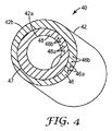
図4は、別の例示的なフィルタ要素40の断面の概略斜視図であり、このフィルタ要素40は多孔質不織布ウェブ42を利用するものである。ウェブ42は、3次元変形44を有している。この例示的な実施形態において、ウェブ42の第1の表面42a及び第2の表面42bは、ウェブ42が概ね円筒状の形状を形成するように、平面的な形状構成から変位している。ウェブ42は、第1及び第2の層46及び48など、2層以上の層を含んでおり、第1及び第2の層46及び48のそれぞれ又は両方は、図1に示すように、多孔質不織布ウェブ10であってもよい。例示的な一実施形態において、第1のウェブ層46は、第1のポリマー繊維46b内に捕らえられた第1の活性粒子46aを含んでおり、第2のウェブ層48は、第2のポリマー繊維48b内に捕らえられた第2の活性粒子48aを含んでいる。好ましくは、第1の層46は、図4に示すように、変形の全体にわたって第2の層48と接触している。そのような例示的なフィルタ要素は、混成ガスの攻撃、例えばアンモニアと有機蒸気に対して使用するように設計された呼吸用保護装置における使用に、特に有利である。
FIG. 4 is a cross-sectional schematic perspective view of another
図5は、別の例示的なフィルタ要素50の横断面図であり、フィルタ要素50は、本開示の他の例示的な実施形態に関連して説明したウェブなど、多孔質不織布ウェブ52を利用するものである。ウェブ52は、2つ以上の3次元変形54を有している。この例示的な実施形態において、ウェブ52の第1の表面52a及び第2の表面52bは、ウェブ52が一連の3次元変形を形成するように、平面的な形状構成から変位している。図示の実施形態において、変形54は、直線的な配列を形成している(変形54は、1つの方向に沿って、反復する列を形成している)。他の例示的な実施形態において、変形54は、2次元配列を形成する(変形54は、2つの方向に沿って、反復する列を形成する)。他の例示的な実施形態において、変形54は、不規則的な配列など、任意の類の分布を形成してよい。個々の変形は、寸法及び/又は形状において類似していてもよく、又は、互いに異なっていてもよい。ウェブ52は、第1及び第2の層56及び58など、2層以上の層を含む。好ましくは、第1の層56は、例えば図5に示すように境界57に沿って、変形の全体にわたって第2の層58と接触している。
FIG. 5 is a cross-sectional view of another
図6は、本開示に従う別の例示的なフィルタ要素150の概略横断面図を示している。例示的なフィルタ要素150は、ハウジング130を含んでいる。図2に示す例示的なウェブなど、本開示に従って構成された多孔質不織布ウェブ120が、ハウジング130の内部に配置されている。ウェブ120は、第1及び第2の層126及び128など、2層以上の層を含んでおり、第1及び第2の層126及び128のそれぞれ又は両方は、上述のように、多孔質不織布ウェブであってもよい。ウェブ32は、3次元変形34を有している。好ましくは、第1の層36は、図3に示すように、変形の全体にわたって第2の層38と接触している。ハウジング130は、開口部133を有するカバー132を含んでいる。環境空気が開口部133を通じてフィルタ要素150に進入し、ウェブ120を通過し(ここで、そのような環境空気中の潜在的有害物質がウェブ120内の活性粒子によって処理される)、支持体137上に装着された吸気弁135を通り越えてハウジング130から抜け出る。
FIG. 6 shows a schematic cross-sectional view of another
差し口138及び差し込み口金139により、フィルタ要素150を、図7に示す呼吸用保護装置160に交換可能に取り付けることができる。装置160は、ときにハーフマスク呼吸用保護具と呼ばれるものであり、比較的薄い硬質な構造部材又はインサート164の周りにインサート成形され得る適合性面体を含んでいる。インサート164は、呼気弁165と、差し込み口金にねじ切りされた凹状の開口部(図7には示さず)とを含んでおり、この開口部は、フィルタ要素150のハウジング130を装置160の頬領域に取り外し可能に取り付けるためのものである。調節式ヘッドバンド166及びネックストラップ168により、装置160は、着用者の鼻及び口を覆って確実に着用されることが可能となる。そのような装置の構造に関する更なる詳細が、当業者には周知であろう。
By means of the
図8は、本開示の例示的な実施形態が用途を見出し得る別の例示的な呼吸用保護装置270を示している。装置270は、ときに使い捨て又はメンテナンスフリーマスクと呼ばれるものであり、概ねカップ状の形状をなすシェル又は呼吸用保護具本体271を有し、この呼吸用保護具本体271は、外側カバーウェブ272と、図2及び3に示す例示的なウェブなど、本開示に従って構成された多孔質不織布ウェブ220と、内側カバーウェブ274とを含んでいる。溶着縁部275がこれらの層を互いに保持し、装置270の縁部を経た漏れを減じるようにフェースシール領域を設けている。装置270は、タブ277によって装置270に締結された調節式ヘッド及びネックストラップ276と、ノーズバンド278と、呼気弁279とを含んでいる。そのような装置の構造に関する更なる詳細が、当業者には周知であろう。
FIG. 8 illustrates another exemplary
図9は、本開示の例示的な実施形態、特に図4に示す例示的な実施形態が用途を見出し得る別の例示的な呼吸用保護装置300を示している。装置300は、集合保護用の空気処理システムにおいて使用されるものなど、ときに半径流濾過システムと呼ばれるものである。図示の実施形態において、入口314は、ハウジング310の内周縁310aに位置している。出口316は、入口314と流体連通するものであり、ハウジング310の外周縁310bに位置してもよい。ハウジングの内部に配置された例示的なフィルタ要素320は、本開示に従う多孔質不織布ウェブ322と、本開示に従う3層の多孔質不織布ウェブ324とを含んでいる。
FIG. 9 illustrates another exemplary
ウェブ322は、ウェブ324の層のうちの1つ以上の材料と異なる材料を含んでもよく、かつ/又は、ウェブ324の層のうちの1つ以上と異なる濾過特性を有してもよい。いくつかの例示的な実施形態において、ウェブ324のある層が、ウェブ324の他の層の1つ以上の材料と異なる材料を含んでもよく、かつ/又は、ウェブ324の層の1つ以上と異なる濾過特性を有してもよい。また、粒子状物質のフィルタ要素330など、付加的なフィルタ要素がハウジング310の内部に設けられてもよい。粒子状物質のフィルタ要素が、好ましくは、フィルタ要素320の上流に設けられる。
一実施形態において、空気又は他の流体が、ハウジング310の内周縁に位置する入口314に送られる。空気は次いで、矢印Fで示すようにフィルタ要素の各々を通過することができ、やがて出口316を通過する。本開示はまた、他の流体処理システムにおいて使用されてもよく、本開示の実施形態は、入口314及び出口316の種々の形状構成及び位置を有し得る。例えば、入口及び出口の位置は、逆転されてもよい。
In one embodiment, air or other fluid is delivered to an
図10は、本開示に従う、3次元変形を有する保形自立性の多孔質不織布ウェブを作製する例示的な方法及び装置900を示している。粒子含有ウェブ920は最初に、平面的な形状構成を有してもよい。本開示に従う3次元変形が、例えば例示的な装置900を使用してウェブ920を成形することによって、ウェブ920に付与されてもよい。装置900は、第1の温度調整式の金型904aと、第2の温度調整式の金型904bとを含んでいる。金型の形状は、ウェブ902への付与が望まれる変形の形状によって決まる。第2の金型904bに向かう第1の金型904aの移動を制御するために、空気圧式のピストン906が使用されてもよい。フレーム902が、金型904a、904b、及びピストン906を支持している。
FIG. 10 illustrates an exemplary method and
3次元変形を有する保形自立性の不織布ウェブを作製する例示的な方法において、ウェブ層922及び924は、金型904aと904bとの間に置かれ、金型は互いに近寄せられ、それにより、金型はウェブ層922と924を圧力と熱にさらし、それにより、ウェブ層922と924は互いに成形され、それにより、ウェブ層922と924は接触し、かつ所望の形状を形成する。金型904a及び904bの温度は、同様となるかあるいは異なることがあり、ウェブ層922及び924の繊維に使用されるポリマーに依存すると予想される。エクソンモービル(ExxonMobil)Vistamaxxブランド2125熱可塑性ポリオレフィンエラストマーが使用される場合、機能すると予想される金型温度は、75℃〜250℃、より好ましくは95℃〜120℃となる。金型904a及び904bによってウェブ層922及び924に及ぼされる圧力は、ウェブ層922及び924の繊維に使用されるポリマーに依存すると予想され、また活性粒子の種類及び量に依存することもある。例えば、エクソンモービル(ExxonMobil)Vistamaxxブランド2125樹脂が使用される場合、機能すると予想される圧力は、20g/cm2〜10000g/cm2、より好ましくは300g/cm2〜2000g/cm2となる。そのような条件下での例示的な成形時間は、2秒間〜30分間と予想される。一般に、成形時間は、温度、圧力、並びに、ポリマー及び活性粒子に依存する。
In an exemplary method for making a shape-retaining self-supporting nonwoven web having three-dimensional deformation, web layers 922 and 924 are placed between
成形プロセスにより、ウェブの熱可塑性エラストマーポリマー繊維が軟化し、付形され、それにより、所望の形状の3次元変形を有する、結果として得られるウェブもまた、ウェブ層922及び924から形成された連続的な層を含むと考えられる。本開示の例示的なプロセスによって形成されたそのような連続的な層は、より分離しにくいものとなり、フィルタ要素構造の耐久性の向上に寄与する。この成形プロセスはまた、自立性及び保形性を持つことが可能なウェブを生産する上で効果的であると考えられる。他の例示的な方法には、加熱された圧板を用いてプレス機上又はプレス機内で、あるいは重りを有する固定具をオーブン内に置くことによって、ウェブ層922及び924を成形することを挙げることができる。
The molding process softens and shapes the thermoplastic elastomeric polymer fibers of the web so that the resulting web having a three-dimensional deformation of the desired shape is also formed from the web layers 922 and 924. It is thought that it includes a typical layer. Such a continuous layer formed by the exemplary process of the present disclosure becomes less separable and contributes to improved durability of the filter element structure. This forming process is also believed to be effective in producing webs that can be self-supporting and shape-retaining. Other exemplary methods include forming
試験方法
本開示に従うフィルタ要素のサンプルの密度を算出するためには、通常、比較的損傷がなく、適度に特徴的なフィルタ要素の片を採取することから始める。これは、例えば、好ましくは、本開示に従う3次元変形の少なくとも一部分がサンプルに含まれるように、検討中のサンプルから一片を切断することによって達成され得る。その片は、「特徴的」と見なされるように、すべての寸法において十分に大きいことが重要である。より具体的には、サンプルは、ウェブ内に分散する活性粒子よりもはるかに大きく、好ましくは、ウェブ内の微粒子の最大寸法の少なくとも5倍、より好ましくは、ウェブ内の微粒子の最大寸法の少なくとも100倍でなければならない。
Test Method In order to calculate the density of a sample of filter elements according to the present disclosure, one usually starts by taking a piece of filter elements that are relatively undamaged and that are reasonably characteristic. This can be accomplished, for example, by cutting a piece from the sample under consideration, preferably so that the sample includes at least a portion of a three-dimensional deformation according to the present disclosure. It is important that the pieces are large enough in all dimensions to be considered “characteristic”. More specifically, the sample is much larger than the active particles dispersed in the web, preferably at least 5 times the largest dimension of the particulates in the web, more preferably at least the largest dimension of the particulates in the web. Must be 100 times.
サンプルの形状は、矩形又は円筒形など、寸法の測定と体積の算出が容易となるように選択されてもよい。曲面の場合、サンプルを切断するために使用される装置(ルールダイ(rule die))で直径を規定できること、例えばルールダイが有利となる場合がある。そのようなサンプルの寸法を測定するために、ASTM D1777−96試験オプション#5を指針として用いることができる。押さえ金の大きさは、利用可能なサンプルの大きさに対応するように調節されなければならない。測定プロセスの間にサンプルを変形させないことが望ましいが、オプション#5での指定を越える高圧も、ある状況下では許容可能となり得る。測定される構造は多孔質であるため、単一の活性粒子と比較して相対的に大きな領域の全体に、接触圧が広がるはずである。特徴的な片の体積を求めた後、特徴的な片の重さを量る。密度は、その重量を体積で除算することによって求められる。 The shape of the sample may be selected to facilitate measurement of dimensions and volume calculation, such as rectangular or cylindrical. In the case of curved surfaces, it may be advantageous to be able to define the diameter with the equipment used to cut the sample (rule die), for example a rule die. ASTM D1777-96 test option # 5 can be used as a guide to measure the dimensions of such samples. The size of the presser foot must be adjusted to correspond to the available sample size. Although it is desirable not to deform the sample during the measurement process, high pressures beyond those specified in Option # 5 may be acceptable under certain circumstances. Since the structure to be measured is porous, the contact pressure should spread over a relatively large area compared to a single active particle. After determining the volume of the characteristic piece, the characteristic piece is weighed. Density is determined by dividing its weight by volume.
また、不織布ウェブ内の粒子状成分の密度を、同じ粒子状材料の「充填ベッド」の密度と比較することによって、本開示の例示的な実施形態の密度を特徴付けることも可能である。これは、既知の体積の「特徴的な片」から粒子状物質を除去し、その結果として得られる粒子状サンプルの重量を量ることを伴う。次いで、「充填ベッド」の体積を得るために、この粒子状物質をメスシリンダーの中に注ぐことができる。これらのデータから、重量を測定値で除算することにより、「充填又は見かけ」密度を算出することができる。しかしながら、その結果は、粒子状物質に付着する残留ポリマーによって歪むことがある。 It is also possible to characterize the density of exemplary embodiments of the present disclosure by comparing the density of the particulate component within the nonwoven web to the density of the “filled bed” of the same particulate material. This involves removing particulate matter from a known volume of “characteristic pieces” and weighing the resulting particulate sample. This particulate material can then be poured into a graduated cylinder to obtain a “packed bed” volume. From these data, the “packed or apparent” density can be calculated by dividing the weight by the measured value. However, the result may be distorted by residual polymer that adheres to the particulate matter.
本開示の方法に従って、以下の層を組み立て、濾過面体呼吸用保護具の形状(カップに似た)へと成形した。 In accordance with the method of the present disclosure, the following layers were assembled and formed into the shape of a filter face respirator (similar to a cup).
1.外側シェル:不織布材料層の層であり、20%はコサ社(Kosa Co.)のタイプ295を1.5インチ(3.8cm)に切断した6デニールのポリエステルステープルファイバ、80%はコサ社(Kosa Co.)のタイプ254を1.5インチ(3.8cm)に切断した4デニールの複合ポリエステル(bico-polyester)ステープルファイバ。
2.ブローンマイクロファイバ濾過材の層。
3.本開示に従う4000gsm(グラム毎平方メートル)の多孔質不織布ウェブの層であり、熱可塑性エラストマーポリオレフィン繊維に捕らえられた、クラレ社(Kuraray)から入手可能な12×20の有機蒸気活性炭粒子、タイプGGを含むもの。
4.本開示に従う600gsmの多孔質不織布ウェブの層であり、熱可塑性エラストマーポリオレフィンポリマー繊維内に捕らえられた40×140の有機蒸気活性炭粒子を含むもの。
5.高密度メルトブローンマイクロファイバの滑らかな不織布ウェブの層。
6.内側シェル:不織布材料層の層であり、20%はコサ社(Kosa Co.)のタイプ295を1.5インチ(3.8cm)に切断した6デニールのポリエステルステープルファイバ、80%はコサ社(Kosa Co.)のタイプ254を1.5インチ(3.8cm)に切断した4デニールの複合ポリエステル(bico-polyester)ステープルファイバ。
1. Outer shell: a layer of nonwoven material, 20% 6-denier polyester staple fiber of Kosa Co. type 295 cut to 1.5 inches (3.8 cm), 80% Kosa ( 4 denier bi-polyester staple fiber cut from Kosa Co. type 254 to 1.5 inches (3.8 cm).
2. A layer of blown microfiber filter media.
3. 12 × 20 organic vapor activated carbon particles, type GG, available from Kuraray, which is a layer of 4000 gsm (gram per square meter) porous non-woven web according to the present disclosure and encapsulated in thermoplastic elastomer polyolefin fibers. Including.
4). A layer of a 600 gsm porous nonwoven web according to the present disclosure, comprising 40 × 140 organic vapor activated carbon particles trapped within a thermoplastic elastomer polyolefin polymer fiber.
5. A smooth nonwoven web layer of high density meltblown microfiber.
6). Inner shell: a layer of nonwoven material, 20% 6-denier polyester staple fiber of Kosa Co. type 295 cut to 1.5 inches (3.8 cm), 80% Kosa ( 4 denier bi-polyester staple fiber cut from Kosa Co. type 254 to 1.5 inches (3.8 cm).
上記の層を、濾過面体呼吸用保護具の成形を目的とした成形装置の中に入れた。上部の金型を235°F(113℃)の温度に設定し、下部の金型を300°F(149℃)の温度に設定した。 The above layer was placed in a molding device intended to mold a filter face respirator. The upper mold was set to a temperature of 235 ° F. (113 ° C.) and the lower mold was set to a temperature of 300 ° F. (149 ° C.).
85L/mと測定されたときに、このようにして形成された呼吸用保護具の通気抵抗は、水柱14.9mm〜33.7mmであった。シクロヘキサンのCEN試験法(試験条件:1000ppm、30Lpm、20C、70% RH、10ppm通気(breathrough))に対して試験すると、成形した呼吸用保護具の構造は、40分間〜59分間の寿命を有した。関連するCEN試験が、英国規格BS EN 141:200「呼吸用保護装置(ガスフィルタ及び複合フィルタ)要件、試験、マーキング(Respiratory protective devices - Gas filters and combined filters - Requirements, testing, marking)」に記載されている。 When measured to be 85 L / m, the ventilation resistance of the respiratory protection device thus formed was 14.9 mm to 33.7 mm of the water column. When tested against the CEN test method for cyclohexane (test conditions: 1000 ppm, 30 Lpm, 20 C, 70% RH, 10 ppm breaththrough), the structure of the molded respirator has a lifetime of 40 minutes to 59 minutes. did. Related CEN test described in British Standard BS EN 141: 200 “Respiratory protective devices-Gas filters and combined filters-Requirements, testing, marking” Has been.
このようにして、「付形した層状の粒子含有不織布ウェブ」の実施形態が開示される。本発明が、開示されたもの以外の実施形態で実施され得ることは、当業者には理解されよう。例えば、本開示に従う3層以上の層が使用され得る。開示された実施形態は、限定ではなく説明を目的として提示されたものであり、本発明は、「特許請求の範囲」によってのみ限定される。 Thus, embodiments of “shaped layered particle-containing nonwoven webs” are disclosed. Those skilled in the art will appreciate that the invention may be practiced with embodiments other than those disclosed. For example, more than two layers according to the present disclosure may be used. The disclosed embodiments are presented for purposes of illustration and not limitation, and the present invention is limited only by the claims.
Claims (24)
前記ウェブは3次元変形を有し、前記第1の層は、前記変形の全体にわたって前記第2の層と接触している、フィルタ要素。 A filter element comprising a porous nonwoven web, the web comprising a first layer and a second layer, wherein the first layer is disposed within the first layer. Thermoplastic elastomeric polymer fibers and first active particles, wherein the second layer includes second thermoplastic elastomeric polymer fibers and second active particles disposed in the second layer;
The filter element, wherein the web has a three-dimensional deformation and the first layer is in contact with the second layer throughout the deformation.
前記ウェブは3次元変形を有し、前記第1の層は、前記変形の全体にわたって前記第2の層と接触しており、
前記3次元変形は、前記変形の全体にわたって少なくとも1つの方向に沿って5倍以下で変動する厚さを特徴とする、フィルタ要素。 A filter element comprising a porous nonwoven web, the web comprising a first layer and a second layer, wherein the first layer is disposed in the first layer. Comprising a second elastomeric polymer fiber and a second active particle disposed therein, the second layer of the second layer comprising a plastic elastomeric polymer fiber and first active particles;
The web has a three-dimensional deformation, and the first layer is in contact with the second layer throughout the deformation;
The filter element characterized in that the three-dimensional deformation has a thickness that varies no more than 5 times along at least one direction throughout the deformation.
前記ウェブは3次元変形を有し、前記第1の層は、前記変形の全体にわたって前記第2の層と接触しており、
前記変形は、その位置における前記ウェブの厚さの少なくとも0.5倍、平面的な形状構成から逸脱することを特徴とする表面を備える、フィルタ要素。 A filter element comprising a porous nonwoven web, the web comprising a first layer and a second layer, wherein the first layer is disposed in the first layer. Comprising a thermoplastic elastomer polymer fiber and first active particles, wherein the second layer comprises a second thermoplastic elastomer polymer fiber and second active particles disposed in the second layer;
The web has a three-dimensional deformation, and the first layer is in contact with the second layer throughout the deformation;
Filter element comprising a surface characterized in that the deformation deviates from a planar configuration at least 0.5 times the thickness of the web at that location.
Applications Claiming Priority (3)
| Application Number | Priority Date | Filing Date | Title |
|---|---|---|---|
| US13875708P | 2008-12-18 | 2008-12-18 | |
| US61/138,757 | 2008-12-18 | ||
| PCT/US2009/066488 WO2010071739A1 (en) | 2008-12-18 | 2009-12-03 | Shaped layered particle-containing nonwoven web |
Publications (2)
| Publication Number | Publication Date |
|---|---|
| JP2012512742A true JP2012512742A (en) | 2012-06-07 |
| JP2012512742A5 JP2012512742A5 (en) | 2013-01-24 |
Family
ID=42269112
Family Applications (1)
| Application Number | Title | Priority Date | Filing Date |
|---|---|---|---|
| JP2011542217A Pending JP2012512742A (en) | 2008-12-18 | 2009-12-03 | Shaped, layered, particle-containing nonwoven web |
Country Status (11)
| Country | Link |
|---|---|
| US (1) | US20110240027A1 (en) |
| EP (1) | EP2370180A4 (en) |
| JP (1) | JP2012512742A (en) |
| KR (1) | KR20110112337A (en) |
| CN (1) | CN102281924B (en) |
| AU (1) | AU2009327443C1 (en) |
| BR (1) | BRPI0918124A2 (en) |
| CA (1) | CA2747388A1 (en) |
| MX (1) | MX2011006362A (en) |
| RU (1) | RU2469756C1 (en) |
| WO (1) | WO2010071739A1 (en) |
Cited By (1)
| Publication number | Priority date | Publication date | Assignee | Title |
|---|---|---|---|---|
| JPWO2019189638A1 (en) * | 2018-03-30 | 2021-02-12 | 東レ株式会社 | Multi-layer filter medium |
Families Citing this family (22)
| Publication number | Priority date | Publication date | Assignee | Title |
|---|---|---|---|---|
| US9345495B2 (en) | 2010-08-16 | 2016-05-24 | Smith & Nephew, Inc. | Systems and methods for altering the surface of a bone |
| JP5884136B2 (en) * | 2011-11-30 | 2016-03-15 | 三ツ星ベルト株式会社 | Method for producing filter molded body |
| US9950202B2 (en) | 2013-02-01 | 2018-04-24 | 3M Innovative Properties Company | Respirator negative pressure fit check devices and methods |
| US11052268B2 (en) | 2013-02-01 | 2021-07-06 | 3M Innovative Properties Company | Respirator negative pressure fit check devices and methods |
| US9517367B2 (en) | 2013-02-01 | 2016-12-13 | 3M Innovative Properties Company | Respiratory mask having a clean air inlet chamber |
| EP3036037A2 (en) * | 2013-08-21 | 2016-06-29 | 3M Innovative Properties Company | Layered or mixed sorbent bed protective filtration device |
| JP2016533885A (en) * | 2013-08-21 | 2016-11-04 | スリーエム イノベイティブ プロパティズ カンパニー | Protective filtration device for stacked or mixed type adsorption bed |
| CN105611995A (en) * | 2013-08-21 | 2016-05-25 | 3M创新有限公司 | Catalytic composition and process using it for the alkylation of aromatic hydrocarbons with alcohols, or mixtures of alcohols and olefins |
| CN103829408A (en) * | 2014-03-25 | 2014-06-04 | 陆拾柒 | Antimicrobic anti-haze mask |
| US10201198B2 (en) * | 2014-12-23 | 2019-02-12 | Profit Royal Pharmaceutical Limited | Protective masks with coating comprising different electrospun fibers interweaved with each other, formulations forming the same, and method of producing thereof |
| WO2017172361A1 (en) | 2016-03-28 | 2017-10-05 | 3M Innovative Properties Company | Multiple chamber respirator sealing devices and methods |
| USD842982S1 (en) | 2016-03-28 | 2019-03-12 | 3M Innovative Properties Company | Hardhat suspension adapter for half facepiece respirators |
| KR102450400B1 (en) | 2016-03-28 | 2022-10-04 | 쓰리엠 이노베이티브 프로퍼티즈 캄파니 | Respiratory compatibility test sealing device and method |
| USD816209S1 (en) | 2016-03-28 | 2018-04-24 | 3M Innovative Properties Company | Respirator inlet port connection seal |
| USD827810S1 (en) | 2016-03-28 | 2018-09-04 | 3M Innovative Properties Company | Hardhat suspension adapter for half facepiece respirators |
| CN105999858A (en) * | 2016-06-28 | 2016-10-12 | 含山县科宇环境工程有限公司 | High-temperature-resistant filter material and production method |
| BR112019002051B1 (en) * | 2016-08-11 | 2022-09-06 | Kimberly-Clark Worldwide, Inc. | THERMOPLATIC POLYOLEFIN ELASTOMER FILM, AND, ARTICLE |
| WO2018206568A1 (en) * | 2017-05-09 | 2018-11-15 | Low & Bonar B.V. | Cushioning structure |
| JP7334056B2 (en) * | 2019-04-26 | 2023-08-28 | ユニ・チャーム株式会社 | absorbent article |
| KR102139160B1 (en) * | 2019-12-16 | 2020-07-29 | (주)브레인엠알오 | Mult-Filtering Mask |
| WO2021222481A1 (en) * | 2020-04-28 | 2021-11-04 | Lcp Medical Technologies, Inc. | Antipathogen respirator |
| CN112370867B (en) * | 2020-10-14 | 2022-05-10 | 新石器科技有限公司 | Preparation method of efficient antibacterial protective mask filter layer |
Citations (4)
| Publication number | Priority date | Publication date | Assignee | Title |
|---|---|---|---|---|
| JPH11500061A (en) * | 1995-02-17 | 1999-01-06 | リーダル・インコーポレーテッド | Filter material for beverage production |
| JP2001525201A (en) * | 1997-12-01 | 2001-12-11 | ミネソタ マイニング アンド マニュファクチャリング カンパニー | Molded respirator containing absorbent particles |
| JP2008519173A (en) * | 2004-11-08 | 2008-06-05 | スリーエム イノベイティブ プロパティズ カンパニー | Particle-containing fiber web |
| JP2008142627A (en) * | 2006-12-11 | 2008-06-26 | Sanden Corp | Antiallergen filter and air cleaning system using the same |
Family Cites Families (8)
| Publication number | Priority date | Publication date | Assignee | Title |
|---|---|---|---|---|
| WO1981001019A1 (en) * | 1979-10-09 | 1981-04-16 | L Giffard | Respiratory mask and filtering material included therein |
| DE3719420A1 (en) * | 1987-06-11 | 1988-12-29 | Sandler Helmut Helsa Werke | RESPIRATORY MASK |
| US6454986B1 (en) * | 1999-10-08 | 2002-09-24 | 3M Innovative Properties Company | Method of making a fibrous electret web using a nonaqueous polar liquid |
| CA2297513A1 (en) * | 2000-01-31 | 2001-07-31 | Pierre Jean Messier | Process for the immobilisation of particles in a three dimensional matrix structure |
| WO2003090873A1 (en) * | 2002-04-26 | 2003-11-06 | Avon Protection Systems, Inc. | Gas mask filter canister |
| WO2005034659A2 (en) * | 2003-08-11 | 2005-04-21 | University Of Tennessee Research Foundation | Fluorochemical electret treatment for barrier fabrics |
| US20060254427A1 (en) * | 2004-11-08 | 2006-11-16 | 3M Innovative Properties Company | Particle-containing fibrous web |
| US7419526B2 (en) * | 2005-03-03 | 2008-09-02 | 3M Innovative Properties Company | Conformal filter cartridges and methods |
-
2009
- 2009-12-03 KR KR1020117016296A patent/KR20110112337A/en not_active Application Discontinuation
- 2009-12-03 JP JP2011542217A patent/JP2012512742A/en active Pending
- 2009-12-03 EP EP09833802.3A patent/EP2370180A4/en not_active Withdrawn
- 2009-12-03 CN CN200980154983.1A patent/CN102281924B/en not_active Expired - Fee Related
- 2009-12-03 US US13/133,051 patent/US20110240027A1/en not_active Abandoned
- 2009-12-03 MX MX2011006362A patent/MX2011006362A/en not_active Application Discontinuation
- 2009-12-03 RU RU2011123104/12A patent/RU2469756C1/en not_active IP Right Cessation
- 2009-12-03 AU AU2009327443A patent/AU2009327443C1/en not_active Ceased
- 2009-12-03 CA CA2747388A patent/CA2747388A1/en not_active Abandoned
- 2009-12-03 WO PCT/US2009/066488 patent/WO2010071739A1/en active Application Filing
- 2009-12-03 BR BRPI0918124A patent/BRPI0918124A2/en not_active IP Right Cessation
Patent Citations (4)
| Publication number | Priority date | Publication date | Assignee | Title |
|---|---|---|---|---|
| JPH11500061A (en) * | 1995-02-17 | 1999-01-06 | リーダル・インコーポレーテッド | Filter material for beverage production |
| JP2001525201A (en) * | 1997-12-01 | 2001-12-11 | ミネソタ マイニング アンド マニュファクチャリング カンパニー | Molded respirator containing absorbent particles |
| JP2008519173A (en) * | 2004-11-08 | 2008-06-05 | スリーエム イノベイティブ プロパティズ カンパニー | Particle-containing fiber web |
| JP2008142627A (en) * | 2006-12-11 | 2008-06-26 | Sanden Corp | Antiallergen filter and air cleaning system using the same |
Cited By (2)
| Publication number | Priority date | Publication date | Assignee | Title |
|---|---|---|---|---|
| JPWO2019189638A1 (en) * | 2018-03-30 | 2021-02-12 | 東レ株式会社 | Multi-layer filter medium |
| JP7322700B2 (en) | 2018-03-30 | 2023-08-08 | 東レ株式会社 | Multilayer filter media |
Also Published As
| Publication number | Publication date |
|---|---|
| RU2469756C1 (en) | 2012-12-20 |
| MX2011006362A (en) | 2011-06-24 |
| CN102281924A (en) | 2011-12-14 |
| CA2747388A1 (en) | 2010-06-24 |
| BRPI0918124A2 (en) | 2015-11-24 |
| KR20110112337A (en) | 2011-10-12 |
| AU2009327443A1 (en) | 2011-07-07 |
| CN102281924B (en) | 2014-07-09 |
| EP2370180A4 (en) | 2014-05-28 |
| US20110240027A1 (en) | 2011-10-06 |
| EP2370180A1 (en) | 2011-10-05 |
| WO2010071739A1 (en) | 2010-06-24 |
| AU2009327443B2 (en) | 2012-08-02 |
| AU2009327443C1 (en) | 2013-02-21 |
Similar Documents
| Publication | Publication Date | Title |
|---|---|---|
| AU2009327443C1 (en) | Shaped layered particle-containing nonwoven web | |
| KR101648600B1 (en) | Filter Element Utilizing Shaped Particle-Containing Nonwoven Web | |
| KR101379171B1 (en) | Particle-containing fibrous web | |
| US8460423B2 (en) | Filter cartridge having central plenum and housing sidewall | |
| CA2799392C (en) | Method of making filter cartridge having roll-based housing sidewall | |
| JP2012513298A (en) | Small multi gas filter | |
| KR20120091127A (en) | Active-particulate air filter having monolith primary filter and polishing filter |
Legal Events
| Date | Code | Title | Description |
|---|---|---|---|
| A521 | Written amendment |
Free format text: JAPANESE INTERMEDIATE CODE: A523 Effective date: 20121130 |
|
| A621 | Written request for application examination |
Free format text: JAPANESE INTERMEDIATE CODE: A621 Effective date: 20121130 |
|
| A977 | Report on retrieval |
Free format text: JAPANESE INTERMEDIATE CODE: A971007 Effective date: 20131023 |
|
| A601 | Written request for extension of time |
Free format text: JAPANESE INTERMEDIATE CODE: A601 Effective date: 20140205 |
|
| A602 | Written permission of extension of time |
Free format text: JAPANESE INTERMEDIATE CODE: A602 Effective date: 20140213 |
|
| A521 | Written amendment |
Free format text: JAPANESE INTERMEDIATE CODE: A523 Effective date: 20140228 |
|
| A02 | Decision of refusal |
Free format text: JAPANESE INTERMEDIATE CODE: A02 Effective date: 20141111 |