RU2467295C1 - Device to diagnose condition of flange protective cartridge of thermoelement - Google Patents
Device to diagnose condition of flange protective cartridge of thermoelement Download PDFInfo
- Publication number
- RU2467295C1 RU2467295C1 RU2011128245/28A RU2011128245A RU2467295C1 RU 2467295 C1 RU2467295 C1 RU 2467295C1 RU 2011128245/28 A RU2011128245/28 A RU 2011128245/28A RU 2011128245 A RU2011128245 A RU 2011128245A RU 2467295 C1 RU2467295 C1 RU 2467295C1
- Authority
- RU
- Russia
- Prior art keywords
- flange
- power
- contact
- control channel
- narrow
- Prior art date
Links
Images
Abstract
Description
Изобретение относится к измерительной технике и может использоваться, в частности, в термометрии, особенно в быстротечных технологических процессах, и там, где можно быстро отреагировать на возможную разгерметизацию защитных гильз термопреобразователей путем измерения давления.The invention relates to measuring equipment and can be used, in particular, in thermometry, especially in fast-flowing technological processes, and where it is possible to quickly respond to possible depressurization of thermowells of thermocouples by measuring pressure.
В патентных источниках аналогов для контроля целостности защитной гильзы термопреобразователя выявить не удалось.In patent sources, analogues for monitoring the integrity of the thermowell of the thermocouple could not be identified.
Известен контроль целостности трубопровода в устройстве для предотвращения катастрофического развития аварийной ситуации, описанный в патенте РФ №2317464 по кл. F16K 17/38, F17D 3/00, 5/00, з. 28.02.06, оп.20.09.07.Known control of the integrity of the pipeline in the device to prevent the catastrophic development of an emergency, described in the patent of the Russian Federation No. 2317464 in class. F16K 17/38, F17D 3/00, 5/00, c. 02.28.06, op.20.09.07.
Известное средство контроля целостности магистрального трубопровода включает в себя датчики давления перекачиваемой по трубопроводу среды, линию передачи сигнала от датчиков давления в центр управления магистрального трубопровода, линию передачи команды для приведения в действие запорных органов, систему распознавания и фиксирования аварийной ситуации на каждом участке, выполненную по типу и в виде охранной сигнализации, основанной на контроле целостности сторожевой электрической цепи между клапанами-отсекателями. Падение давления перекачиваемой среды служит сигналом нарушения целостности трубопровода.A well-known means of monitoring the integrity of the main pipeline includes pressure sensors of the medium pumped through the pipeline, a signal transmission line from the pressure sensors to the control center of the main pipeline, a command transmission line for actuating the locking elements, an emergency recognition and detection system for each section, executed by type and in the form of burglar alarms based on monitoring the integrity of the watchdog circuit between the shutoff valves. The pressure drop in the pumped medium is a signal of violation of the integrity of the pipeline.
Система является достаточно сложной и используется для трубопроводов.The system is quite complex and is used for pipelines.
Известно температурное измерительное устройство с узлом контроля утечки рабочего материала в окружающую среду путем измерения давления, описанное в материалах фирмы CatTracker (см. сайт www.cattracker.ru/index.php?page=cattracker «Многозонные гибкие термопары, характеристики, конструкция: CatTrack…», 2009-2011 гг.Known temperature measuring device with a unit for monitoring the leakage of the working material into the environment by measuring pressure, described in the materials of the company CatTracker (see website www.cattracker.ru/index.php?page=cattracker "Multi-zone flexible thermocouples, characteristics, design: CatTrack ... ", 2009-2011
Известное устройство содержит измерительный зонд термопреобразователя в защитной гильзе с посадочным фланцем, обеспечивающим механическое герметичное соединение с технологической установкой, контрольный узел давления в виде узла обнаружения утечки, включающего клиновую задвижку, спускной клапан, тройник, манометр, патрубки, и вспомогательную защитную камеру для предотвращения утечки, представляющую собой промежуточную герметичную полость, расположенную между оболочкой погружной части термопреобразователя и окружающей средой, а также соединительную коробку для коммутационной аппаратуры и соединительных кабелей и механически соединенную с ними с обеих сторон и связанную также с узлом обнаружения утечки.The known device contains a measuring probe of the thermocouple in a protective sleeve with a flange that provides a mechanical tight connection with the technological installation, a pressure monitoring unit in the form of a leak detection unit, including a wedge gate valve, a drain valve, a tee, a pressure gauge, pipes, and an auxiliary protective chamber to prevent leakage , which is an intermediate sealed cavity located between the shell of the immersion of the thermocouple and the environment, and t Also a junction box for switchgear and jumper cables and mechanically connected to them on both sides and also connected to a leak detection unit.
Недостатком известного устройства является сложность конструкции узла, обусловленная наличием объемной (громоздкой) специальной промежуточной полости, приводящей к увеличению времени выявления негерметичности защитной гильзы и увеличивающей длину измерительного зонда.A disadvantage of the known device is the complexity of the design of the node, due to the presence of a volumetric (bulky) special intermediate cavity, leading to an increase in the time for detecting leaks in the protective sleeve and increasing the length of the measuring probe.
Задачей является упрощение конструкции и уменьшение ее габаритов при уменьшении времени выявления неисправности защитной гильзы.The objective is to simplify the design and reduce its dimensions while reducing the time to detect a malfunction of the thermowell.
Поставленная задача решается тем, что в устройстве диагностики состояния фланцевой защитной гильзы термопреобразователя, включающем контрольный узел давления, связанный через канал контроля с термопреобразователем, состоящим из измерительного зонда в защитной гильзе с посадочным фланцем, обеспечивающим герметичное соединение измерительного зонда в защитной гильзе с технологической установкой, при этом канал контроля выполнен в виде промежуточной герметичной полости, образованной между рабочей средой и окружающим пространством, согласно изобретению посадочный фланец выполнен составным - из силового и контактного фланцев, а промежуточная герметичная полость образована последовательно сообщающимися между собой узким сквозным отверстием в силовом фланце, частью внутренней цилиндрической поверхности уплотнительной прокладки между фланцами, выбранным в силовом фланце горизонтальным узким пазом, ограниченным плоскостью контактного фланца, кольцевой фаской на центральном отверстии силового фланца, зазором между цилиндрической поверхностью этого же отверстия и лыской на посадочной поверхности защитной гильзы в верхней части контактного фланца, а также узким кольцевым зазором между измерительным зондом, его уплотнительным кольцом и защитной гильзой.The problem is solved in that in the device for diagnosing the condition of the flange thermowell of the thermocouple, including the pressure control unit connected through the control channel to the thermocouple, consisting of a measuring probe in the thermowell with a mounting flange, which provides a tight connection of the measuring probe in the thermowell with the technological unit, the control channel is made in the form of an intermediate sealed cavity formed between the working medium and the surrounding space, with According to the invention, the landing flange is made integral of the power and contact flanges, and the intermediate sealed cavity is formed by successively communicating with each other by a narrow through hole in the power flange, part of the inner cylindrical surface of the gasket between the flanges, a horizontal narrow groove selected in the power flange bounded by the plane of the contact flange , an annular chamfer on the central hole of the power flange, a gap between the cylindrical surface of the same hole and yskoy on the seat surface of the protective sleeve in the upper portion of the contact flange, and a narrow annular gap between the measuring probe and its sealing ring and the protective sleeve.
При этом канал контроля может быть связан с контрольным узлом давления через штуцер на силовом фланце или через гнездо в нем.In this case, the control channel can be connected to the control pressure unit through a fitting on the power flange or through a socket in it.
Выполнение посадочного фланца составным - из силового и контактного фланцев в совокупности с получением промежуточной герметичной полости канала контроля из зазоров и отверстий между элементами конструкции термопреобразователя, как указано выше, позволяет упростить конструкцию устройства, уменьшить его габариты и сократить время выявления неисправности.The implementation of the mounting flange composite - from the power and contact flanges in conjunction with obtaining an intermediate tight cavity of the control channel from the gaps and holes between the structural elements of the thermal converter, as described above, allows to simplify the design of the device, reduce its dimensions and reduce the time of detection of malfunctions.
Технический результат - упрощение конструкции при уменьшении объема промежуточной герметичной полости, что дает уменьшение времени отклика на возможную неисправность защитной гильзы и уменьшение габаритов конструкции.The technical result is a simplification of the design while reducing the volume of the intermediate sealed cavity, which reduces the response time to a possible malfunction of the thermowell and reduces the dimensions of the structure.
Заявляемое устройство обладает новизной в сравнении с прототипом, отличаясь от него такими существенными признаками, как выполнение посадочного фланца составным - из силового и контактного фланцев, и выполнение канала контроля в конструкции самого термопреобразователя образованием промежуточной герметичной полости из последовательно сообщающихся между собой узким сквозным отверстием в силовом фланце, выбранным в нем же пазом, ограниченным плоскостью контактного фланца, кольцевой фаской на центральном отверстии силового фланца, зазором между цилиндрической поверхностью этого же отверстия и лыской на посадочной поверхности трубы в верхней части контактного фланца, а также узким кольцевым зазором между измерительным зондом, его уплотнительным кольцом и защитной гильзой, обеспечивающими в совокупности достижение заданного результата.The inventive device has a novelty in comparison with the prototype, differing from it by such significant features as the construction of the mounting flange composite of power and contact flanges, and the implementation of the control channel in the design of the thermocouple by forming an intermediate sealed cavity from successively communicating with each other through a narrow through hole in the power a flange, a groove selected in it, bounded by the plane of the contact flange, an annular chamfer on the central hole of the power flange, The gap between the cylindrical surface of the same hole and the flat on the pipe seating surface in the upper part of the contact flange, as well as the narrow annular gap between the measuring probe, its sealing ring and the protective sleeve, together provide the desired result.
Заявителю неизвестны технические решения, обладающие указанными отличительными признаками, обеспечивающими в совокупности достижение заданного результата, поэтому он считает, что заявляемое устройство соответствует критерию «изобретательский уровень».The applicant is not aware of technical solutions that have the indicated distinguishing features, which together ensure the achievement of a given result, therefore, he believes that the claimed device meets the criterion of "inventive step".
Заявляемое устройство может найти широкое применение в измерительной технике, а потому соответствует критерию «промышленная применимость».The inventive device can be widely used in measuring technology, and therefore meets the criterion of "industrial applicability".
Изобретение иллюстрируется чертежами, где показаны на:The invention is illustrated by drawings, where shown in:
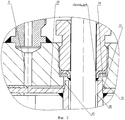
- фиг.1 - конструкция устройства в разрезе;- figure 1 - sectional view of the device;
- фиг.2 - увеличенный вид части канала контроля.- figure 2 is an enlarged view of a portion of the control channel.
Устройство диагностики состояния фланцевой защитной гильзы термопреобразователя (фиг.1) включает контрольный узел 1 давления, связанный с термопреобразователем 2, состоящим из измерительного зонда 3 в защитной гильзе 4 и посадочного фланца 5, обеспечивающего герметичное соединение измерительного зонда в защитной гильзе с технологической установкой. Контрольный узел 1 сообщается с каналом 6 контроля, образованным отверстиями и зазорами в конструкции узлов самого термопреобразователя 2. Посадочный фланец 5 выполнен составным - из силового и контактного фланцев 7 и 8. Канал 6 контроля в виде промежуточной герметичной полости образован последовательно сообщающимися между собой узким сквозным отверстием 9 в силовом фланце 7, выбранным в нем же пазом 10, ограниченным плоскостью контактного фланца 8 и внутренней поверхностью 11 прокладки между фланцами, кольцевой фаской 12 на центральном отверстии 13 силового фланца 7, зазором 14 между цилиндрической поверхностью этого же отверстия и лыской 15 на посадочной поверхности защитной гильзы 3 в верхней части контактного фланца 8, а также узким кольцевым зазором 16 между измерительным зондом 3, его уплотнительным кольцом 18 и защитной гильзой 4.The device for diagnosing the condition of the flange thermowell of the thermocouple (Fig. 1) includes a pressure control unit 1 connected to the thermocouple 2, consisting of a measuring probe 3 in the protective sleeve 4 and the mounting flange 5, which provides a tight connection of the measuring probe in the protective sleeve with the technological unit. The control unit 1 communicates with the control channel 6 formed by holes and gaps in the design of the nodes of the thermal converter 2. The landing flange 5 is made integral - from the power and contact flanges 7 and 8. The control channel 6 in the form of an intermediate sealed cavity is formed by a narrow, through
Промежуточная герметичная полость 6 связана с контрольным узлом 1 давления, в частности, через штуцер 17 на силовом фланце 7.The intermediate tight cavity 6 is connected with the pressure control unit 1, in particular, through the fitting 17 on the power flange 7.
Устройство работает следующим образом.The device operates as follows.
При нарушении целостности защитной гильзы 4 термопреобразователя 2 давление Р рабочей среды передается из узкого кольцевого зазора 16 между измерительным зондом 3, его уплотнительным кольцом 18 и защитной гильзой 4 контактного фланца 8, через зазор между цилиндрической поверхностью центрального отверстия силового фланца 7 и лыской 15 на посадочной цилиндрической поверхности защитной гильзы 4 в верхней части контактного фланца 8, через зазор 19 между фаской 12 на центральном отверстии силового фланца и посадочной цилиндрической поверхностью защитной гильзы 4, горизонтальный паз 10 между силовым и контактным фланцами 7 и 8, узкое сквозное отверстие 9 в силовом фланце 7 и через штуцер 17 на контрольный узел 1 давления, где замеряется (возможно, просто обнаруживается) и индицируется (возможно, просто сигнализируется). Оператор обнаруживает показания узла 1 и быстро принимает решение о ходе техпроцесса и замене защитной гильзы 4.If the integrity of the protective sleeve 4 of the thermocouple 2 is violated, the pressure P of the working medium is transferred from the narrow
В сравнении с прототипом заявляемое устройство диагностики состояния фланцевой защитной гильзы термопреобразователя является более простым по конструкции и имеет уменьшенные габариты при уменьшении времени выявления неисправности защитной гильзы.In comparison with the prototype of the inventive device for diagnosing the condition of the flange thermowell of the thermocouple is simpler in design and has a reduced size while reducing the time to detect a malfunction of the thermowell.
Claims (3)
Priority Applications (1)
| Application Number | Priority Date | Filing Date | Title |
|---|---|---|---|
| RU2011128245/28A RU2467295C1 (en) | 2011-07-07 | 2011-07-07 | Device to diagnose condition of flange protective cartridge of thermoelement |
Applications Claiming Priority (1)
| Application Number | Priority Date | Filing Date | Title |
|---|---|---|---|
| RU2011128245/28A RU2467295C1 (en) | 2011-07-07 | 2011-07-07 | Device to diagnose condition of flange protective cartridge of thermoelement |
Publications (1)
| Publication Number | Publication Date |
|---|---|
| RU2467295C1 true RU2467295C1 (en) | 2012-11-20 |
Family
ID=47323311
Family Applications (1)
| Application Number | Title | Priority Date | Filing Date |
|---|---|---|---|
| RU2011128245/28A RU2467295C1 (en) | 2011-07-07 | 2011-07-07 | Device to diagnose condition of flange protective cartridge of thermoelement |
Country Status (1)
| Country | Link |
|---|---|
| RU (1) | RU2467295C1 (en) |
Cited By (2)
| Publication number | Priority date | Publication date | Assignee | Title |
|---|---|---|---|---|
| CN104568196A (en) * | 2015-01-04 | 2015-04-29 | 安徽蓝德仪表有限公司 | Platinum rhodium thermal coupler |
| RU2666193C1 (en) * | 2017-11-24 | 2018-09-06 | Акционерное общество "Научно-производственное объединение Измерительной техники" (АО "НПО ИТ") | High-temperature hermetic thermal converter |
Citations (2)
| Publication number | Priority date | Publication date | Assignee | Title |
|---|---|---|---|---|
| RU2317464C2 (en) * | 2006-02-28 | 2008-02-20 | Государственное образовательное учреждение высшего профессионального образования "Уфимский государственный нефтяной технический университет" | Method and device for preventing emergency situation in damaging main pipeline |
| RU2366059C1 (en) * | 2008-07-21 | 2009-08-27 | Владимир Степанович Белов | Method of controlling and diagnosing technical state of turbo-generators |
-
2011
- 2011-07-07 RU RU2011128245/28A patent/RU2467295C1/en active
Patent Citations (2)
| Publication number | Priority date | Publication date | Assignee | Title |
|---|---|---|---|---|
| RU2317464C2 (en) * | 2006-02-28 | 2008-02-20 | Государственное образовательное учреждение высшего профессионального образования "Уфимский государственный нефтяной технический университет" | Method and device for preventing emergency situation in damaging main pipeline |
| RU2366059C1 (en) * | 2008-07-21 | 2009-08-27 | Владимир Степанович Белов | Method of controlling and diagnosing technical state of turbo-generators |
Non-Patent Citations (1)
| Title |
|---|
| CatTracker (см. сайт www. cattracker.ru/index. php?page=cattracker «Многозонные гибкие термопары, характеристики, конструкция: CatTrack...», 2009-2010. * |
Cited By (3)
| Publication number | Priority date | Publication date | Assignee | Title |
|---|---|---|---|---|
| CN104568196A (en) * | 2015-01-04 | 2015-04-29 | 安徽蓝德仪表有限公司 | Platinum rhodium thermal coupler |
| CN104568196B (en) * | 2015-01-04 | 2019-06-11 | 安徽蓝德仪表有限公司 | A kind of platinum rhodium thermocouple |
| RU2666193C1 (en) * | 2017-11-24 | 2018-09-06 | Акционерное общество "Научно-производственное объединение Измерительной техники" (АО "НПО ИТ") | High-temperature hermetic thermal converter |
Similar Documents
| Publication | Publication Date | Title |
|---|---|---|
| JP6675515B2 (en) | Leakage detection | |
| US11427992B2 (en) | System for monitoring backflow preventer condition | |
| US9255649B2 (en) | Apparatus for fluid control device leak detection | |
| US20230304886A1 (en) | Valve diagnostic and performance system | |
| CN105070332A (en) | Monitoring system for preventing leakage of main steam pipeline in nuclear power plant | |
| RU2467295C1 (en) | Device to diagnose condition of flange protective cartridge of thermoelement | |
| KR20160109330A (en) | system for detecting leakage of valve | |
| US8806970B2 (en) | Sealing device for a device for measuring the fill level in a fluid container | |
| US4315432A (en) | Enclosure for protecting instruments against adverse environments | |
| EP4222396A1 (en) | Valve diagnostic and performance system | |
| JP4630769B2 (en) | Leak test method and temperature sensitive member used therefor | |
| US10317003B2 (en) | Double block and bleed system for an orifice fitting | |
| US11441697B2 (en) | Valve diagnostic and performance system | |
| JP2015108442A (en) | Trap | |
| US10533669B2 (en) | Bi-directional flow control valve | |
| JP6754721B2 (en) | Steam system water level detector | |
| JP6375194B2 (en) | trap | |
| RU94336U1 (en) | THERMOELECTRIC CONVERTER | |
| US11852248B2 (en) | Packing system and diagnostic method for a packing system of a valve assembly | |
| US20220333360A1 (en) | System for monitoring backflow preventer condition | |
| JP2007205511A (en) | Monitor device of valve | |
| US20190234822A1 (en) | Hot-swappable access/retrieval plug for high pressure fluid systems | |
| RU115471U1 (en) | THERMAL CONVERTER |