RU2467194C2 - Turbojet engine unloader, and turbojet engine with said unloader - Google Patents
Turbojet engine unloader, and turbojet engine with said unloader Download PDFInfo
- Publication number
- RU2467194C2 RU2467194C2 RU2008105068/06A RU2008105068A RU2467194C2 RU 2467194 C2 RU2467194 C2 RU 2467194C2 RU 2008105068/06 A RU2008105068/06 A RU 2008105068/06A RU 2008105068 A RU2008105068 A RU 2008105068A RU 2467194 C2 RU2467194 C2 RU 2467194C2
- Authority
- RU
- Russia
- Prior art keywords
- unloading
- discharge
- openings
- holes
- intermediate housing
- Prior art date
Links
Images


Classifications
-
- F—MECHANICAL ENGINEERING; LIGHTING; HEATING; WEAPONS; BLASTING
- F01—MACHINES OR ENGINES IN GENERAL; ENGINE PLANTS IN GENERAL; STEAM ENGINES
- F01D—NON-POSITIVE DISPLACEMENT MACHINES OR ENGINES, e.g. STEAM TURBINES
- F01D17/00—Regulating or controlling by varying flow
- F01D17/10—Final actuators
- F01D17/105—Final actuators by passing part of the fluid
-
- F—MECHANICAL ENGINEERING; LIGHTING; HEATING; WEAPONS; BLASTING
- F02—COMBUSTION ENGINES; HOT-GAS OR COMBUSTION-PRODUCT ENGINE PLANTS
- F02C—GAS-TURBINE PLANTS; AIR INTAKES FOR JET-PROPULSION PLANTS; CONTROLLING FUEL SUPPLY IN AIR-BREATHING JET-PROPULSION PLANTS
- F02C9/00—Controlling gas-turbine plants; Controlling fuel supply in air- breathing jet-propulsion plants
- F02C9/16—Control of working fluid flow
- F02C9/18—Control of working fluid flow by bleeding, bypassing or acting on variable working fluid interconnections between turbines or compressors or their stages
-
- F—MECHANICAL ENGINEERING; LIGHTING; HEATING; WEAPONS; BLASTING
- F02—COMBUSTION ENGINES; HOT-GAS OR COMBUSTION-PRODUCT ENGINE PLANTS
- F02K—JET-PROPULSION PLANTS
- F02K3/00—Plants including a gas turbine driving a compressor or a ducted fan
- F02K3/02—Plants including a gas turbine driving a compressor or a ducted fan in which part of the working fluid by-passes the turbine and combustion chamber
- F02K3/04—Plants including a gas turbine driving a compressor or a ducted fan in which part of the working fluid by-passes the turbine and combustion chamber the plant including ducted fans, i.e. fans with high volume, low pressure outputs, for augmenting the jet thrust, e.g. of double-flow type
- F02K3/075—Plants including a gas turbine driving a compressor or a ducted fan in which part of the working fluid by-passes the turbine and combustion chamber the plant including ducted fans, i.e. fans with high volume, low pressure outputs, for augmenting the jet thrust, e.g. of double-flow type controlling flow ratio between flows
-
- F—MECHANICAL ENGINEERING; LIGHTING; HEATING; WEAPONS; BLASTING
- F04—POSITIVE - DISPLACEMENT MACHINES FOR LIQUIDS; PUMPS FOR LIQUIDS OR ELASTIC FLUIDS
- F04D—NON-POSITIVE-DISPLACEMENT PUMPS
- F04D27/00—Control, e.g. regulation, of pumps, pumping installations or pumping systems specially adapted for elastic fluids
- F04D27/02—Surge control
- F04D27/0207—Surge control by bleeding, bypassing or recycling fluids
- F04D27/023—Details or means for fluid extraction
-
- F—MECHANICAL ENGINEERING; LIGHTING; HEATING; WEAPONS; BLASTING
- F04—POSITIVE - DISPLACEMENT MACHINES FOR LIQUIDS; PUMPS FOR LIQUIDS OR ELASTIC FLUIDS
- F04D—NON-POSITIVE-DISPLACEMENT PUMPS
- F04D29/00—Details, component parts, or accessories
- F04D29/40—Casings; Connections of working fluid
- F04D29/52—Casings; Connections of working fluid for axial pumps
- F04D29/522—Casings; Connections of working fluid for axial pumps especially adapted for elastic fluid pumps
-
- Y—GENERAL TAGGING OF NEW TECHNOLOGICAL DEVELOPMENTS; GENERAL TAGGING OF CROSS-SECTIONAL TECHNOLOGIES SPANNING OVER SEVERAL SECTIONS OF THE IPC; TECHNICAL SUBJECTS COVERED BY FORMER USPC CROSS-REFERENCE ART COLLECTIONS [XRACs] AND DIGESTS
- Y02—TECHNOLOGIES OR APPLICATIONS FOR MITIGATION OR ADAPTATION AGAINST CLIMATE CHANGE
- Y02T—CLIMATE CHANGE MITIGATION TECHNOLOGIES RELATED TO TRANSPORTATION
- Y02T50/00—Aeronautics or air transport
- Y02T50/60—Efficient propulsion technologies, e.g. for aircraft
Abstract
Description
Настоящее изобретение относится к области авиационных турбореактивных двигателей с истечением первичного и вторичного воздуха.The present invention relates to the field of aircraft turbojet engines with the expiration of primary and secondary air.
Более конкретно, оно относится к разгрузочным устройствам для турбореактивных двигателей и к турбореактивному двигателю, снабженному таким разгрузочным устройством.More specifically, it relates to discharge devices for turbojet engines and to a turbojet engine equipped with such a discharge device.
Известен авиационный турбореактивный двигатель с истечением первичного и вторичного воздуха, содержащий первичный поток истечения газа и вторичный поток истечения газа, которые разделены промежуточной оболочкой, которая является структурной деталью. В первичном потоке по ходу истечения газа от начала к концу размещены компрессор низкого давления и компрессор высокого давления. Сжатый таким образом воздух поступает в камеру сгорания, в которой смешивается с топливом под давлением, которое поджигается, для передачи на выходе из камеры сгорания энергии турбине высокого давления, которая вращает компрессор высокого давления, затем турбину низкого давления. Давление выходящего из турбин газа добавляется к общему давлению газа вторичного потока для обеспечения движения самолета.Known aircraft turbojet engine with the outflow of primary and secondary air containing a primary stream of gas flow and a secondary stream of gas flow, which are separated by an intermediate shell, which is a structural part. A low-pressure compressor and a high-pressure compressor are placed in the primary stream along the gas flow from the beginning to the end. Thus compressed air enters the combustion chamber, in which it is mixed with fuel under pressure, which is ignited, to transfer energy to the high-pressure turbine, which rotates the high-pressure compressor, and then the low-pressure turbine, at the outlet of the combustion chamber. The pressure of the gas exiting the turbines is added to the total gas pressure of the secondary stream to ensure the movement of the aircraft.
При некоторых режимах полета количество воздуха, вырабатываемого компрессором низкого давления, является повышенным для правильного функционирования турбореактивного двигателя, поэтому существует необходимость в переводе части этого воздуха во вторичный поток, чтобы избежать феномена рыскания, вызванного отрывом струек жидкости, стекающих вдоль лопастей, вызывающих нестабильность обтекания.In some flight modes, the amount of air produced by the low-pressure compressor is increased for the turbojet engine to function properly, so there is a need to transfer part of this air to the secondary stream in order to avoid the phenomenon of yaw caused by separation of the liquid streams flowing along the blades causing instability of the flow around.
Отвод воздуха называется также воздушной разгрузкой. Он осуществляется разгрузочным устройством. The air outlet is also called air discharge. It is carried out by an unloading device.
Широко известное разгрузочное устройство выполнено в виде подвижных шарнирных заслонок, одновременно приводимых в действие приводными средствами. Такое разгрузочное устройство с заслонками описано в патенте US 3638428. Пример устройства с заслонками представлен на фиг. 10, на котором показан первичный поток воздуха 110, при этом устройство содержит компрессор низкого давления 112, и поток вторичного воздуха 114, который окружает первичный поток воздуха 110. Оба потока 110, 114 являются кольцевыми и разделены межпотоковым отсеком 117, выполненным в виде кольцевого отсека с внутренней оболочкой 116 и внешней оболочкой 118. Промежуточная оболочка 120, являющаяся структуральной, простирается на секцию турбореактивного двигателя и связывает внутреннюю оболочку 116 и внешнюю оболочку 118. Промежуточная оболочка 120 содержит удерживающие рычаги 122, которые простираются радиально от внешней оболочки 118 внутрь потока 114. Эти удерживающие рычаги 22 позволяют передать усилие двигателя на структуру самолета. Их обычно бывает от восьми до двенадцати.The widely known unloading device is made in the form of movable hinged shutters, simultaneously driven by drive means. Such a discharge device with flaps is described in US Pat. No. 3,638,428. An example of a device with flaps is shown in FIG. 10, which shows a
Выше удерживающих рычагов 122 внутренний поток 114 содержит также систему выходных направляющих лопаток, которые радиально простираются от внешней оболочки 118 и функцией которых является выравнивание потока воздуха после его прохождения через лопатки вентилятора (не показанного на чертеже).Above the
Течение в первичном потоке 110 показано стрелкой 190. Течение во вторичном потоке показано стрелкой 192. Разгрузка или отвод воздуха от первичного потока 110 во вторичный поток 114 представлено стрелкой 194. Разгрузка осуществляется через внутренние отверстия 126 внутренней оболочки 116 и внешние отверстия 128 внешней оболочки 118 посредством подвижных задвижек 130, размещенных во внутреннем отсеке 117 между внутренней оболочкой 116 и внешней оболочкой 116. Подвижные задвижки 130 приводятся в действие гидроцилиндрами 164 таким образом, чтобы синхронно закрыть внутренние отверстия 126. Внешние отверстия 128 не перекрываются. Они выполнены в виде решетки, распределенной по окружности внешней оболочки 118, и размещены на уровне промежуточной оболочки между удерживающими рычагами 122.The flow in the
Устройство разгрузки из известного уровня техники, которое было описано выше со ссылкой на фиг.10, не соответствует концепции современных турбореактивных двигателей, габариты и массу, согласно которой стараются уменьшить их. Для этого стремятся уменьшить радиальный размер турбореактивных двигателей, и было предложено поместить выходные направляющие лопатки в ту же аксиальную секцию промежуточной оболочки, что и удерживающие рычаги, и даже придать удерживающим рычагам направляющие профили. Например, на промежуточной оболочке размещаются удерживающие рычаги, между которыми распределены направляющие лопатки. Как следствие, в этой секции не остается места для размещения открытых наружу решеток, необходимых для разгрузки. Кроме того, даже если было бы возможно выделить место для размещения и позиционирования таких разгружающих решеток, имеются другие причины для опасений. Действительно, первичный поток (стрелки 190) часто содержит загрязнения, такие как льдинки, при попадании которых в разгрузочный поток (стрелки 194) могут быть разрушены выходные направляющие лопатки, размещенные между удерживающими рычагами, так как направляющие лопатки выполнены, как правило, из композитного материала или алюминия.The unloading device of the prior art, which was described above with reference to figure 10, does not correspond to the concept of modern turbojet engines, dimensions and weight, according to which they try to reduce them. To do this, they seek to reduce the radial size of turbojet engines, and it was proposed to place the output guide vanes in the same axial section of the intermediate shell as the holding levers, and even to give the holding levers guide profiles. For example, holding levers are placed on the intermediate shell, between which guide vanes are distributed. As a result, in this section there is no room for placement of the outwardly open grates necessary for unloading. In addition, even if it would be possible to allocate space for the placement and positioning of such discharge grids, there are other reasons for concern. Indeed, the primary stream (arrows 190) often contains contaminants, such as ice, if it enters the discharge stream (arrows 194), the output guide vanes located between the holding arms can be destroyed, since the guide vanes are usually made of composite material or aluminum.
Изобретение имеет задачей устранение указанных выше недостатков. Для решения поставленной задачи предлагается устройство для разгрузки, позволяющее осуществить отвод воздуха из первичного потока во вторичный и которое соответствует концепции турбореактивного двигателя, в котором выходные направляющие лопатки размещены в той же секции, что и удерживающие рычаги.The invention has the task of eliminating the above disadvantages. To solve this problem, an unloading device is proposed that allows air to be drawn from the primary stream to the secondary one and which corresponds to the concept of a turbojet engine in which the output guide vanes are located in the same section as the holding levers.
В соответствии с первым аспектом изобретение относится к устройству разгрузки, предназначенному для отвода части первичного потока к вторичному потоку турбореактивного двигателя, при этом указанный турбореактивный двигатель имеет первичный поток истечения воздуха и вторичный поток истечения воздуха, между которыми находится отсек с внутренней оболочкой, отделяющей указанный первичный поток, и внешней оболочкой, отделяющей указанный вторичный поток, при этом указанный турбореактивный двигатель имеет промежуточный картер, снабженный входной и выходной стенками, причем устройство разгрузки содержит внутренние отверстия внутренней оболочки, размещенные на входе промежуточного картера; внешние отверстия внешней оболочки, размещенные на выходе промежуточного картера; линию разгрузки, связывающую указанные внутренние отверстия с указанными внешними отверстиями через промежуточный отсек; средства перекрывания, способные открывать и закрывать указанную линию разгрузки, отличающееся тем, что линия разгрузки содержит отверстия на входе промежуточного картера; отверстия на выходе промежуточного картера; кольцевой канал, размещенный между промежуточным картером, внешней оболочкой и связывающей камерой, при этом указанная связывающая камера опирается на промежуточный картер таким образом, чтобы закрыть его входные отверстия в указанный канал, и опирается на внешнюю оболочку таким образом, чтобы закрыть внешние отверстия в указанном кольцевом канале.According to a first aspect, the invention relates to an unloading device for diverting a portion of the primary stream to a secondary stream of a turbojet engine, said turbojet engine having a primary air flow and a secondary air flow, between which there is a compartment with an inner shell separating said primary the flow, and an outer shell separating the specified secondary stream, while the specified turbojet engine has an intermediate crankcase, equipped with th input and output walls, and the unloading device contains internal holes of the inner shell located at the inlet of the intermediate housing; outer holes of the outer shell located at the outlet of the intermediate housing; an unloading line connecting said internal openings to said external openings through an intermediate compartment; means of overlapping, capable of opening and closing the specified discharge line, characterized in that the discharge line contains holes at the inlet of the intermediate crankcase; openings at the outlet of the intermediate housing; an annular channel located between the intermediate housing, the outer shell and the connecting chamber, wherein said connecting chamber is supported on the intermediate housing in such a way as to close its inlet openings in the specified channel, and is supported on the external shell in such a way as to close the outer holes in the specified annular channel.
Предпочтительно, чтобы входные отверстия промежуточного кожуха были выполнены во входной стенке последнего, а выходные отверстия были выполнены в выходной стенке последнего.Preferably, the inlets of the intermediate casing are made in the inlet wall of the latter, and the outlets are made in the outlet wall of the latter.
Предпочтительно также, чтобы устройство разгрузки содержало коллектор, размещенный на входе промежуточного кожуха и содержащий разгрузочные проходы, соединяющие внутренние отверстия внутренней оболочки и входные отверстия промежуточной оболочки.It is also preferable that the discharge device comprises a collector located at the inlet of the intermediate casing and containing discharge passages connecting the inner holes of the inner shell and the inlets of the intermediate shell.
Предпочтительно также, чтобы разгрузочное устройство содержало столько же отверстий на входе, сколько и на выходе, и, кроме того, содержало направляющие трубы, установленные между входной стенкой промежуточного кожуха, при этом каждая направляющая труба должна связывать одно входное отверстие с соответствующим выходным отверстием.It is also preferable that the unloading device contains as many openings at the inlet as there are at the outlet, and furthermore comprises guide pipes installed between the inlet wall of the intermediate casing, with each guide pipe connecting one inlet to a corresponding outlet.
Средство перекрывания содержит разгрузочное кольцо, снабженное разгрузочными окнами и размещенное на входе промежуточного кожуха. Указанное разгрузочное кольцо способно перемещаться вращаясь вокруг оси, между положением открывания линии разгрузки, в котором каждое упомянутое разгрузочное окно соответствует, по меньшей мере, частично, проходам линии разгрузки, и положением закрывания линии разгрузки, в котором каждое разгрузочное окно не соответствует указанным проходам линии разгрузки.The overlapping means comprises an unloading ring provided with unloading windows and placed at the inlet of the intermediate casing. Said discharge ring is capable of moving around an axis, between the opening position of the discharge line, in which each said discharge window corresponds, at least in part, to the passages of the discharge line, and the closing position of the discharge line, in which each discharge window does not correspond to said passages of the discharge line .
В положении полного открывания линии разгрузки каждое разгрузочное окно разгрузочного кольца полностью совпадает с разгрузочным проходом коллектора. В положении полного закрывания линии разгрузки каждое разгрузочное окно разгрузочного кольца не совпадает с частью разгрузочного прохода коллектора.In the fully open position of the discharge line, each discharge window of the discharge ring fully coincides with the discharge passage of the collector. In the fully closed position of the discharge line, each discharge window of the discharge ring does not coincide with a part of the discharge passage of the collector.
Средства перекрывания содержат приводные средства указанного разгрузочного кольца для управления перемещением последнего между указанными позициями полного открывания и полного закрывания линии разгрузки.The overlapping means comprise drive means of said discharge ring for controlling the movement of the latter between said full opening and closing positions of the discharge line.
Средства привода содержат, по меньшей мере, одну направляющую прорезь, выполненную во входной стенке промежуточного кожуха по кольцевому направлению.The drive means comprise at least one guide slot made in the annular direction in the input wall of the intermediate casing.
Средства привода содержат, по меньшей мере, одну ось управления разгрузочным кольцом. Ход оси ограничен краями указанной направляющей прорези.The drive means comprise at least one control axis of the discharge ring. The axis travel is limited by the edges of the specified slot guide.
Средства привода содержат, по меньшей мере, один гидроцилиндр, сочлененный с указанной осью управления и размещенный внутри отсека между верхней и нижней стенками промежуточного кожуха.The drive means comprise at least one hydraulic cylinder articulated with said control axis and located inside the compartment between the upper and lower walls of the intermediate casing.
В соответствии с другим вариантом, изобретение относится к турбореактивному двигателю, содержащему устройство разгрузки по первому варианту.According to another embodiment, the invention relates to a turbojet engine comprising a discharge device according to the first embodiment.
В дальнейшем изобретение поясняется нижеследующим описанием, не являющимся ограничительным, со ссылками на сопровождающие фигуры, в числе которых:The invention is further explained in the following description, which is not restrictive, with reference to the accompanying figures, including:
фиг.1 изображает в аксиальном разрезе разгрузочное устройство по изобретению;figure 1 depicts in axial section of a discharge device according to the invention;
фиг.2 изображает в аксонометрии разгрузочное устройство по изобретению в продольном разрезе;figure 2 depicts a perspective view of the unloading device according to the invention in longitudinal section;
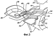
фиг.3 изображает вид в аксонометрии крупным планом разгрузочного устройства в разрезе по продольной оси, представляющий соединение разгрузочного кольца с коллектором;figure 3 depicts a perspective view of a close-up of the discharge device in section along the longitudinal axis, representing the connection of the discharge ring with the manifold;
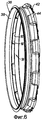
фиг.4 изображает вид в аксонометрии перед разгрузочным кольцом;figure 4 depicts a perspective view in front of the discharge ring;
фиг.5 изображает вид в аксонометрии за коллектором;5 is a perspective view of the collector;
фиг.6-8 изображают вид в аксонометрии комплекса, образованного коллектором и кольцом разгрузки, когда линия разгрузки полностью открыта, частично открыта и полностью закрыта;6-8 depict a perspective view of the complex formed by the collector and the discharge ring when the discharge line is fully open, partially open and completely closed;
фиг.9 изображает вид в аксонометрии средства привода кольца разгрузки;Fig.9 depicts a perspective view of a means of driving a discharge ring;
фиг.10 уже описанная, представляет вид в аксиальном разрезе разгрузочного устройства из известного уровня техники.10, already described, is an axial sectional view of a discharge device of the prior art.
В дальнейшем термины «радиальный», «аксиальный» и «кольцевой» касаются турбореактивного двигателя, и термины «верхний» и «нижний» касаются направления течения газов в турбореактивном двигателе.Hereinafter, the terms “radial”, “axial” and “annular” refer to a turbojet engine, and the terms “upper” and “lower” refer to the direction of gas flow in a turbojet engine.
На фиг.1 представлена в осевом разрезе часть турбореактивного двигателя, центрованного вокруг промежуточной оболочки 20, и показана часть первичного потока, в котором циркулирует первичная струя 10, обозначенная стрелками 90, и вторичная струя 14, направление которой обозначено стрелками 92. Промежуточный картер содержит верхнюю стенку 202 и нижнюю стенку 204. Он содержит также удерживающие рычаги 22, которые простираются радиально во вторичном потоке 14 от внешней оболочки 18 и закреплены на верхней стенку 202 и нижней стенке 204. Он содержит также выходные направляющие лопатки, которые радиально размещены во вторичном потоке от внешней оболочки 18. В частности, межпотоковый отсек 17 содержит промежуточную часть, называемую межпотоковой полостью 19, ограниченную внешней оболочкой 18, внутренней оболочкой 16, верхней стенкой 202 промежуточного картера 20 и верхней стенкой 204 промежуточного кожуха 20.Figure 1 shows in axial section a part of a turbojet engine centered around an
Разгрузочный поток первичной струи 10 к вторичной струе 14 показан стрелками 94. Он выходит из первичной струи 10 через внутренние отверстия 26 внутренней оболочки 16 и проникает во вторичную струю через внешнее отверстие 28 внешней оболочки 18. Оно проходит через верхнее отверстие 32 верхней стенки 202 и нижнее отверстие 34 нижней стенки 204.The discharge stream of the
Между внутренними отверстиями 26 и верхними отверстиями 32 промежуточного картера 20 разгрузочный поток 94 направляется по коллектору 36. Коллектор 36 представлен в аксонометрии на виде сзади на фиг.5 и выполнен в виде кольцевой детали, имеющей верхнюю зону 38 и нижнюю зону 40. Верхняя зона 38 является кольцевой, которая является продолжением внутренней оболочки 16. Нижняя зона 40 содержит фиксирующий фланец 42 для ее фиксации на верхней стенке 202 промежуточного картера 20. Коллектор 36 содержит в нижней зоне 40 разгрузочные проходы 44 в количестве, равном количеству отверстий 32 верхней стенки 202. В иллюстрируемом примере количество разгрузочных проходов 44 равно десяти. Они простираются от внутренней поверхности 46 до нижней зоны 48 нижней зоны 40, при этом указанная нижняя зона 48 является площадью контакта между фиксирующим фланцем 42 и промежуточным картером 20, когда коллектор 36 прикреплен к нему. Они открываются во внутреннюю поверхность 46 внутренними отверстиями 50.Between the
Между нижними отверстиями 34 промежуточного картера 20 и внешними отверстиями 28 разгрузочный поток 94 направляется по кольцевому каналу 52. Последний ограничен нижней стенкой 204 промежуточного картера 20, внешней оболочкой 18 сверху промежуточного картера 20 и соединительной камерой 54, которая связывает указанную внешнюю оболочку 18 и указанную внешнюю стенку 204 таким образом, чтобы перекрыть внешние отверстия 28 и нижние отверстия 34 в указанном кольцевом канале 52.Between the
В соответствии с предпочтительным вариантом осуществления изобретения, который показан на чертежах, разгрузочный поток 94 проходит между верхними отверстиями 32 и нижними отверстиями 34 промежуточного картера 20 по направляющим трубам 56, которые проходят строго в аксиальном направлении через межпотоковую полость 19 межпотокового отсека 17, размещенного между верхней 202 и нижней 204 стенками промежуточного картера 20. При наличии направляющих труб 56 количество верхних отверстий 32 и нижних отверстий 34 должно быть одинаковым. В приводимом примере их количество равно десяти. Направляющие трубы 56 предпочтительно используются для направления полного разгрузочного потока 194, который в противном случае заполнял бы межпотоковую полость 19 межпотокового отсека 17 между верхней 202 и нижней 204 стенками промежуточного картера 20 с возможностью попадания в полость 19 таких фрагментов как лед или песок.In accordance with a preferred embodiment of the invention, which is shown in the drawings, the
Коллектор 36, верхние отверстия 22, нижние отверстия 34, кольцевой канал 52 и направляющие трубы 56 при их наличии образуют цепь разгрузки 36, 56, 34, 52 между внутренними отверстиями 26 внутренней оболочки 16 и внешними отверстиями 28 внешней оболочки 18.The
Разгрузочное устройство по изобретению содержит внутренние отверстия 26, отверстия 28 и линию разгрузки. Оно содержит также средства перекрывания 58, 60, 62, 64, 66 указанной линии разгрузки.The unloading device according to the invention contains
Средства перекрывания 58, 60, 62, 64, 66 содержат разгрузочное кольцо 58, представленное в аксонометрии на фиг.4. Разгрузочное кольцо 58 содержит разгрузочные окна 60, число которых, форма и размеры соответствуют числу, форме и размерам внутренних отверстий 50 коллектора 36. В рассматриваемом примере их число равняется десяти.Means of overlapping 58, 60, 62, 64, 66 contain a
При сборке разгрузочное кольцо 58 центрируется по внутренней поверхности 46 коллектора 36 с возможностью быть провернутым между двумя крайними положениями. Точнее говоря, разгрузочное кольцо 58 установлено напротив внутренней поверхности 46 нижней зоны 40 коллектора 36 и приводится во вращение этой внутренней поверхностью 46.When assembling, the
Крайние положения так же, как и промежуточное положение частичного открытия, проиллюстрированы на фиг.6-8.The extreme positions as well as the intermediate position of the partial opening are illustrated in Fig.6-8.
Фиг.6 представляет вид в аксонометрии разгрузочного кольца 58, сочлененного с коллектором 36 в положении полного открывания линии разгрузки, в котором разгрузочное кольцо 58 повернуто таким образом, что его разгрузочные окна 60 точно размещены напротив внутренних отверстий 50 разгрузочных проходов 44 коллектора 36.6 is a perspective view of a
Фиг.7 представляет вид в аксонометрии разгрузочного кольца 58, сочлененного с коллектором 36 в положении частичного открывания - или частичного закрывания - линии разгрузки, в котором разгрузочное кольцо 58 повернуто таким образом, чтобы его разгрузочные окна 60 частично перекрывали внутренние отверстия 50 разгрузочных проходов 44 коллектора 36 и частично перекрывали внутреннюю поверхность 46 последнего.Fig. 7 is a perspective view of a
Фиг.8 представляет вид в аксонометрии разгрузочного кольца 58, сочлененного с коллектором 36 в положении полного перекрывания разгрузочной линии, в которой разгрузочное кольцо 58 повернуто таким образом, что его разгрузочные окна 60 не совпадают с внутренними отверстиями 50 разгрузочных проходов 44 коллектора 36, а совпадают с внутренней поверхностью последнего.Fig. 8 is a perspective view of a
Средства перекрывания 58, 60, 62, 64, 66 содержат также средства привода 62, 64, 66 разгрузочного кольца 58, которое показано на фиг.9.Means for overlapping 58, 60, 62, 64, 66 also contain means for driving 62, 64, 66 of the
В примере выполнения, показанном на чертежах, разгрузочное кольцо 58 снабжено, по меньшей мере, одной управляющей осью 62, которая направлена строго в осевом направлении относительно разгрузочного кольца 58. Предпочтительно, разгрузочное кольцо 58 снабжено двумя управляющими осями 62. Такие управляющие оси 62 размещены между окнами 60 разгрузочного кольца 58. Каждая управляющая ось 62 соединена с гидроцилиндром 64, который размещен либо в межпотоковй полости 19 между верхней стенкой 202 и нижней стенкой 204 промежуточного картера 20, либо в межпотоковом отсеке 17. С этой целью каждая управляющая ось 62 проходит через верхнюю стенку 202 промежуточного картера 20. Точнее говоря, каждая управляющая ось 62 проходит через управляющую прорезь 66, выполненную в этой верхней стенке 202 между двумя верхними отверстиями. Управляющая ось 62 упирается в края управляющей прорези 66. Ход управляющей оси 62 ограничен краями управляющей прорези 66. Последняя размещена таким образом, чтобы ход управляющей оси 62 позволял разгрузочному кольцу 58 перемещаться между двумя крайними желаемыми положениями линии разгрузки. Таким образом, один из упоров управляющей оси 62 соответствует положению полного открывания разгрузочного кольца 58, в то время как другой упор управляющей оси соответствует положению полного закрывания разгрузочного кольца 58.In the exemplary embodiment shown in the drawings, the unloading
Фиг.3 представляет вид в аксонометрии и в поперечном разрезе линии разгрузки. Она представляет коллектор 36, закрепленный на верхней стенке 202 промежуточного картера 20, а также разгрузочное кольцо 58 и коллектор 36, сочлененные в положении полного открывания линии разгрузки. На разрезе видно внутреннее отверстие 26, разгрузочный проход 44 и верхнее отверстие 32. На этом чертеже видно, что внутренняя оболочка межпотокового отсека образована на этом уровне турбореактивного двигателя верхней зоной 38 коллектора 36 кольцевой деталью 70 и промежуточным картером 20. Кольцевая деталь 70 является частью кольцевой связи, жестко соединенной с верхней стенкой 202 промежуточного картера 20 с помощью средств фиксации 72, например болтов, и на которой центрируется разгрузочное кольцо 58. С целью упрощения направляющие трубы 56 не показаны на фиг.3.Figure 3 is a perspective view and in cross section of a discharge line. It represents a manifold 36 mounted on the
Фиг.2 представляет в уменьшенном виде аксонометрию и разрез линии разгрузки. На ней показан коллектор 36, жестко закрепленной на верхней стенке 202 промежуточного картера 20. Этот чертеж представляет также нижнее отверстие 34 нижней стенки 204 промежуточного картера 20 и верхнее отверстие 26 внешней оболочки 18, а также кольцевой канал 52. Последний образован внешней оболочкой 18, нижней стенкой 204 промежуточного картера 20 и соединительной камерой 54. Кроме того, фиг.2 показывает выходные направляющие лопасти 24 и удерживающий рычаг 22, жестко установленные на верхней 202 и нижней 204 стенках внутреннего картера 20. С целью упрощения на фиг.2 не показаны направляющие трубы 56.Figure 2 is a reduced view of a perspective view and a section of a discharge line. It shows a manifold 36, rigidly mounted on the
Claims (13)
Applications Claiming Priority (2)
| Application Number | Priority Date | Filing Date | Title |
|---|---|---|---|
| FR0701000A FR2912466A1 (en) | 2007-02-12 | 2007-02-12 | DISCHARGE DEVICE FOR A TURBOJET AND TURBOJET COMPRISING THE SAME |
| FR0701660 | 2007-03-07 |
Publications (2)
| Publication Number | Publication Date |
|---|---|
| RU2008105068A RU2008105068A (en) | 2009-08-20 |
| RU2467194C2 true RU2467194C2 (en) | 2012-11-20 |
Family
ID=38370392
Family Applications (1)
| Application Number | Title | Priority Date | Filing Date |
|---|---|---|---|
| RU2008105068/06A RU2467194C2 (en) | 2007-02-12 | 2008-02-11 | Turbojet engine unloader, and turbojet engine with said unloader |
Country Status (7)
| Country | Link |
|---|---|
| US (1) | US8075246B2 (en) |
| EP (1) | EP1956226B1 (en) |
| JP (1) | JP5057520B2 (en) |
| CA (1) | CA2620782C (en) |
| DE (1) | DE602008000090D1 (en) |
| FR (1) | FR2912466A1 (en) |
| RU (1) | RU2467194C2 (en) |
Families Citing this family (7)
| Publication number | Priority date | Publication date | Assignee | Title |
|---|---|---|---|---|
| US20120070271A1 (en) * | 2010-09-21 | 2012-03-22 | Urban Justin R | Gas turbine engine with bleed duct for minimum reduction of bleed flow and minimum rejection of hail during hail ingestion events |
| DE102012007130A1 (en) | 2012-04-10 | 2013-10-10 | Rolls-Royce Deutschland Ltd & Co Kg | Aircraft gas turbine with a discharge channel in a guide root element of a bypass duct |
| US9328735B2 (en) | 2012-09-28 | 2016-05-03 | United Technologies Corporation | Split ring valve |
| DE102013202786B4 (en) * | 2013-02-20 | 2015-04-30 | Rolls-Royce Deutschland Ltd & Co Kg | Device for blowing off compressor air in a turbofan engine |
| US10247043B2 (en) * | 2014-12-31 | 2019-04-02 | General Electric Company | Ducted cowl support for a gas turbine engine |
| US11149653B2 (en) * | 2018-08-14 | 2021-10-19 | Raytheon Technologies Corporation | Bleed valve actuation system having split ring segments and splice bracket |
| US11927140B1 (en) | 2023-04-21 | 2024-03-12 | Rtx Corporation | Gas turbine engine with guided bleed air dump |
Citations (6)
| Publication number | Priority date | Publication date | Assignee | Title |
|---|---|---|---|---|
| US3638428A (en) * | 1970-05-04 | 1972-02-01 | Gen Electric | Bypass valve mechanism |
| US5123240A (en) * | 1990-03-19 | 1992-06-23 | General Electric Co. | Method and apparatus for ejecting foreign matter from the primary flow path of a gas turbine engine |
| EP1249618A1 (en) * | 2001-04-12 | 2002-10-16 | Snecma Moteurs | Bleed system for a turbofan with simplified control |
| EP1308601A1 (en) * | 2001-10-31 | 2003-05-07 | Snecma Moteurs | Bleed device for a turbofan |
| RU2002129118A (en) * | 2001-10-31 | 2004-05-10 | Снекма Мотер | TWO-CIRCUIT TURBOREACTIVE ENGINE |
| EP1531236A2 (en) * | 2003-11-13 | 2005-05-18 | United Technologies Corporation | Compressor housing with bleed apertures of a gas turbine engine |
Family Cites Families (6)
| Publication number | Priority date | Publication date | Assignee | Title |
|---|---|---|---|---|
| FR2569783B1 (en) * | 1984-09-06 | 1986-09-12 | Snecma | RING STRUCTURE AND COMPRESSOR DISCHARGE DEVICE COMPRISING THE RING |
| CN1017276B (en) * | 1988-02-17 | 1992-07-01 | 通用电气公司 | Fluidic multiplexer |
| CA2062887A1 (en) * | 1991-04-22 | 1992-10-23 | Franklin E. Miller | Heat exchanger system |
| GB2259328B (en) * | 1991-09-03 | 1995-07-19 | Gen Electric | Gas turbine engine variable bleed pivotal flow splitter |
| US6092987A (en) * | 1998-02-27 | 2000-07-25 | United Technologies Corporation | Stator assembly for a rotary machine |
| JP2002195196A (en) * | 2000-12-26 | 2002-07-10 | Ishikawajima Harima Heavy Ind Co Ltd | Bleed structure of axial compressor |
-
2007
- 2007-02-12 FR FR0701000A patent/FR2912466A1/en not_active Withdrawn
-
2008
- 2008-02-08 DE DE602008000090T patent/DE602008000090D1/en active Active
- 2008-02-08 JP JP2008028525A patent/JP5057520B2/en active Active
- 2008-02-08 EP EP08101436A patent/EP1956226B1/en active Active
- 2008-02-11 RU RU2008105068/06A patent/RU2467194C2/en active
- 2008-02-11 CA CA2620782A patent/CA2620782C/en active Active
- 2008-02-11 US US12/028,994 patent/US8075246B2/en active Active
Patent Citations (6)
| Publication number | Priority date | Publication date | Assignee | Title |
|---|---|---|---|---|
| US3638428A (en) * | 1970-05-04 | 1972-02-01 | Gen Electric | Bypass valve mechanism |
| US5123240A (en) * | 1990-03-19 | 1992-06-23 | General Electric Co. | Method and apparatus for ejecting foreign matter from the primary flow path of a gas turbine engine |
| EP1249618A1 (en) * | 2001-04-12 | 2002-10-16 | Snecma Moteurs | Bleed system for a turbofan with simplified control |
| EP1308601A1 (en) * | 2001-10-31 | 2003-05-07 | Snecma Moteurs | Bleed device for a turbofan |
| RU2002129118A (en) * | 2001-10-31 | 2004-05-10 | Снекма Мотер | TWO-CIRCUIT TURBOREACTIVE ENGINE |
| EP1531236A2 (en) * | 2003-11-13 | 2005-05-18 | United Technologies Corporation | Compressor housing with bleed apertures of a gas turbine engine |
Also Published As
| Publication number | Publication date |
|---|---|
| DE602008000090D1 (en) | 2009-10-01 |
| CA2620782C (en) | 2014-08-19 |
| CA2620782A1 (en) | 2008-08-12 |
| US20080193279A1 (en) | 2008-08-14 |
| US8075246B2 (en) | 2011-12-13 |
| RU2008105068A (en) | 2009-08-20 |
| EP1956226B1 (en) | 2009-08-19 |
| JP5057520B2 (en) | 2012-10-24 |
| FR2912466A1 (en) | 2008-08-15 |
| JP2008196492A (en) | 2008-08-28 |
| EP1956226A1 (en) | 2008-08-13 |
Similar Documents
| Publication | Publication Date | Title |
|---|---|---|
| RU2467194C2 (en) | Turbojet engine unloader, and turbojet engine with said unloader | |
| US9476362B2 (en) | Turbomachine with bleed valves located at the intermediate case | |
| RU2222708C2 (en) | Simplified control bypass gas-turbine engine with means of extraction of excess air | |
| US8092153B2 (en) | Bypass air scoop for gas turbine engine | |
| US4177006A (en) | Turbocharger control | |
| JP6782235B2 (en) | Exhaust gas turbocharger with bypass valve and combination type adjusting device for flow connection | |
| CN101341320B (en) | Multi-stage exhaust turbosupercharger | |
| US3557549A (en) | Turbocharger system for internal combustion engine | |
| RU2126492C1 (en) | Gas-turbine engine (variants) | |
| CN106468218A (en) | Compressor bleed air auxiliary turbine | |
| JP2005507044A (en) | Passive cooling system for auxiliary power plant equipment | |
| RU2296887C2 (en) | Two-loop turbojet engine | |
| CN100564841C (en) | The compressor that has secondary boost air outlet passage | |
| CN101849089A (en) | Multi-stage turbocharger system | |
| RU2714386C2 (en) | Combustion module at constant volume for gas turbine engine | |
| CN113153526A (en) | Mixed flow turbine core | |
| US20060230759A1 (en) | Variable geometry turbocharger | |
| CN206352525U (en) | The asymmetric turbocharger of engine | |
| JP3803326B2 (en) | engine | |
| US9239006B2 (en) | Gas turbine engine and system for modulating secondary air flow | |
| US11111855B2 (en) | Inlet particle separator | |
| RU2496029C2 (en) | Gas-dynamic wave pressure exchanger | |
| US5129225A (en) | Diverter valve | |
| JP2010013972A (en) | Variable capacity type turbocharger | |
| JPS5938429B2 (en) | Silencer for exhaust turbo supercharger |
Legal Events
| Date | Code | Title | Description |
|---|---|---|---|
| TK4A | Correction to the publication in the bulletin (patent) |
Free format text: AMENDMENT TO CHAPTER -FG4A- IN JOURNAL: 32-2012 FOR TAG: (30) |
|
| PD4A | Correction of name of patent owner |