RU2464130C2 - Wireless electronic tool with fuel cell and case there for - Google Patents
Wireless electronic tool with fuel cell and case there for Download PDFInfo
- Publication number
- RU2464130C2 RU2464130C2 RU2009132709/02A RU2009132709A RU2464130C2 RU 2464130 C2 RU2464130 C2 RU 2464130C2 RU 2009132709/02 A RU2009132709/02 A RU 2009132709/02A RU 2009132709 A RU2009132709 A RU 2009132709A RU 2464130 C2 RU2464130 C2 RU 2464130C2
- Authority
- RU
- Russia
- Prior art keywords
- fuel
- battery
- power tool
- housing
- secondary battery
- Prior art date
Links
Images


Classifications
-
- B—PERFORMING OPERATIONS; TRANSPORTING
- B25—HAND TOOLS; PORTABLE POWER-DRIVEN TOOLS; MANIPULATORS
- B25F—COMBINATION OR MULTI-PURPOSE TOOLS NOT OTHERWISE PROVIDED FOR; DETAILS OR COMPONENTS OF PORTABLE POWER-DRIVEN TOOLS NOT PARTICULARLY RELATED TO THE OPERATIONS PERFORMED AND NOT OTHERWISE PROVIDED FOR
- B25F5/00—Details or components of portable power-driven tools not particularly related to the operations performed and not otherwise provided for
- B25F5/02—Construction of casings, bodies or handles
-
- H—ELECTRICITY
- H01—ELECTRIC ELEMENTS
- H01M—PROCESSES OR MEANS, e.g. BATTERIES, FOR THE DIRECT CONVERSION OF CHEMICAL ENERGY INTO ELECTRICAL ENERGY
- H01M50/00—Constructional details or processes of manufacture of the non-active parts of electrochemical cells other than fuel cells, e.g. hybrid cells
- H01M50/20—Mountings; Secondary casings or frames; Racks, modules or packs; Suspension devices; Shock absorbers; Transport or carrying devices; Holders
- H01M50/247—Mountings; Secondary casings or frames; Racks, modules or packs; Suspension devices; Shock absorbers; Transport or carrying devices; Holders specially adapted for portable devices, e.g. mobile phones, computers, hand tools or pacemakers
-
- B—PERFORMING OPERATIONS; TRANSPORTING
- B25—HAND TOOLS; PORTABLE POWER-DRIVEN TOOLS; MANIPULATORS
- B25F—COMBINATION OR MULTI-PURPOSE TOOLS NOT OTHERWISE PROVIDED FOR; DETAILS OR COMPONENTS OF PORTABLE POWER-DRIVEN TOOLS NOT PARTICULARLY RELATED TO THE OPERATIONS PERFORMED AND NOT OTHERWISE PROVIDED FOR
- B25F5/00—Details or components of portable power-driven tools not particularly related to the operations performed and not otherwise provided for
-
- B—PERFORMING OPERATIONS; TRANSPORTING
- B25—HAND TOOLS; PORTABLE POWER-DRIVEN TOOLS; MANIPULATORS
- B25H—WORKSHOP EQUIPMENT, e.g. FOR MARKING-OUT WORK; STORAGE MEANS FOR WORKSHOPS
- B25H3/00—Storage means or arrangements for workshops facilitating access to, or handling of, work tools or instruments
- B25H3/006—Storage means specially adapted for one specific hand apparatus, e.g. an electric drill
-
- H—ELECTRICITY
- H01—ELECTRIC ELEMENTS
- H01M—PROCESSES OR MEANS, e.g. BATTERIES, FOR THE DIRECT CONVERSION OF CHEMICAL ENERGY INTO ELECTRICAL ENERGY
- H01M10/00—Secondary cells; Manufacture thereof
- H01M10/42—Methods or arrangements for servicing or maintenance of secondary cells or secondary half-cells
- H01M10/46—Accumulators structurally combined with charging apparatus
-
- H—ELECTRICITY
- H01—ELECTRIC ELEMENTS
- H01M—PROCESSES OR MEANS, e.g. BATTERIES, FOR THE DIRECT CONVERSION OF CHEMICAL ENERGY INTO ELECTRICAL ENERGY
- H01M16/00—Structural combinations of different types of electrochemical generators
- H01M16/003—Structural combinations of different types of electrochemical generators of fuel cells with other electrochemical devices, e.g. capacitors, electrolysers
- H01M16/006—Structural combinations of different types of electrochemical generators of fuel cells with other electrochemical devices, e.g. capacitors, electrolysers of fuel cells with rechargeable batteries
-
- H—ELECTRICITY
- H01—ELECTRIC ELEMENTS
- H01M—PROCESSES OR MEANS, e.g. BATTERIES, FOR THE DIRECT CONVERSION OF CHEMICAL ENERGY INTO ELECTRICAL ENERGY
- H01M8/00—Fuel cells; Manufacture thereof
- H01M8/04—Auxiliary arrangements, e.g. for control of pressure or for circulation of fluids
- H01M8/04082—Arrangements for control of reactant parameters, e.g. pressure or concentration
- H01M8/04201—Reactant storage and supply, e.g. means for feeding, pipes
- H01M8/04208—Cartridges, cryogenic media or cryogenic reservoirs
-
- H—ELECTRICITY
- H01—ELECTRIC ELEMENTS
- H01M—PROCESSES OR MEANS, e.g. BATTERIES, FOR THE DIRECT CONVERSION OF CHEMICAL ENERGY INTO ELECTRICAL ENERGY
- H01M2250/00—Fuel cells for particular applications; Specific features of fuel cell system
- H01M2250/30—Fuel cells in portable systems, e.g. mobile phone, laptop
-
- H—ELECTRICITY
- H01—ELECTRIC ELEMENTS
- H01M—PROCESSES OR MEANS, e.g. BATTERIES, FOR THE DIRECT CONVERSION OF CHEMICAL ENERGY INTO ELECTRICAL ENERGY
- H01M8/00—Fuel cells; Manufacture thereof
- H01M8/10—Fuel cells with solid electrolytes
- H01M8/1009—Fuel cells with solid electrolytes with one of the reactants being liquid, solid or liquid-charged
- H01M8/1011—Direct alcohol fuel cells [DAFC], e.g. direct methanol fuel cells [DMFC]
-
- Y—GENERAL TAGGING OF NEW TECHNOLOGICAL DEVELOPMENTS; GENERAL TAGGING OF CROSS-SECTIONAL TECHNOLOGIES SPANNING OVER SEVERAL SECTIONS OF THE IPC; TECHNICAL SUBJECTS COVERED BY FORMER USPC CROSS-REFERENCE ART COLLECTIONS [XRACs] AND DIGESTS
- Y02—TECHNOLOGIES OR APPLICATIONS FOR MITIGATION OR ADAPTATION AGAINST CLIMATE CHANGE
- Y02B—CLIMATE CHANGE MITIGATION TECHNOLOGIES RELATED TO BUILDINGS, e.g. HOUSING, HOUSE APPLIANCES OR RELATED END-USER APPLICATIONS
- Y02B90/00—Enabling technologies or technologies with a potential or indirect contribution to GHG emissions mitigation
- Y02B90/10—Applications of fuel cells in buildings
-
- Y—GENERAL TAGGING OF NEW TECHNOLOGICAL DEVELOPMENTS; GENERAL TAGGING OF CROSS-SECTIONAL TECHNOLOGIES SPANNING OVER SEVERAL SECTIONS OF THE IPC; TECHNICAL SUBJECTS COVERED BY FORMER USPC CROSS-REFERENCE ART COLLECTIONS [XRACs] AND DIGESTS
- Y02—TECHNOLOGIES OR APPLICATIONS FOR MITIGATION OR ADAPTATION AGAINST CLIMATE CHANGE
- Y02E—REDUCTION OF GREENHOUSE GAS [GHG] EMISSIONS, RELATED TO ENERGY GENERATION, TRANSMISSION OR DISTRIBUTION
- Y02E60/00—Enabling technologies; Technologies with a potential or indirect contribution to GHG emissions mitigation
- Y02E60/10—Energy storage using batteries
-
- Y—GENERAL TAGGING OF NEW TECHNOLOGICAL DEVELOPMENTS; GENERAL TAGGING OF CROSS-SECTIONAL TECHNOLOGIES SPANNING OVER SEVERAL SECTIONS OF THE IPC; TECHNICAL SUBJECTS COVERED BY FORMER USPC CROSS-REFERENCE ART COLLECTIONS [XRACs] AND DIGESTS
- Y02—TECHNOLOGIES OR APPLICATIONS FOR MITIGATION OR ADAPTATION AGAINST CLIMATE CHANGE
- Y02E—REDUCTION OF GREENHOUSE GAS [GHG] EMISSIONS, RELATED TO ENERGY GENERATION, TRANSMISSION OR DISTRIBUTION
- Y02E60/00—Enabling technologies; Technologies with a potential or indirect contribution to GHG emissions mitigation
- Y02E60/30—Hydrogen technology
- Y02E60/50—Fuel cells
Landscapes
- Engineering & Computer Science (AREA)
- Electrochemistry (AREA)
- Life Sciences & Earth Sciences (AREA)
- General Chemical & Material Sciences (AREA)
- Chemical & Material Sciences (AREA)
- Chemical Kinetics & Catalysis (AREA)
- Mechanical Engineering (AREA)
- Sustainable Development (AREA)
- Sustainable Energy (AREA)
- Computer Hardware Design (AREA)
- Biophysics (AREA)
- Manufacturing & Machinery (AREA)
- Fuel Cell (AREA)
- Portable Power Tools In General (AREA)
- Secondary Cells (AREA)
- Workshop Equipment, Work Benches, Supports, Or Storage Means (AREA)
Abstract
Description
Область техники, к которой относится изобретениеFIELD OF THE INVENTION
Настоящее изобретение относится к беспроводному электроинструменту с устанавливаемым в корпусе рабочим органом (инструментом), приводимым в движение электродвигателем, использующим в качестве приводного блока питания батарею, закрепленную в корпусе электроинструмента и, в частности, к узлу беспроводного электроинструмента, способному обеспечить движущую силу, а также к укладочному кейсу для электроинструмента.The present invention relates to a cordless power tool with a working body (tool) installed in the housing, driven by an electric motor using a battery mounted in a power tool housing as a drive power unit, and in particular, to a cordless power tool assembly capable of providing a driving force, and to a styling case for a power tool.
Предшествующий уровень техникиState of the art
Известен электроинструмент (ручной инструмент с силовым приводом), такой как ударная дрель, не требующий использования промышленного источника питания, подключаемого по электрическому проводу, который может быть применен в таких местах, как строительные площадки, на которых отсутствует силовая установка. Как описано в JP-A-2006-324064, в качестве приводного блока питания беспроводного электроинструмента в основном используют вторичные батареи, такие как никель-кадмиевая батарея (NiCd аккумулятор), никель-водородная батарея или литий-ионная батарея.A known power tool (a hand tool with a power drive), such as a hammer drill that does not require the use of an industrial power source, connected via an electric wire, which can be used in places such as construction sites where there is no power plant. As described in JP-A-2006-324064, secondary batteries, such as a nickel-cadmium battery (NiCd battery), a nickel-hydrogen battery or a lithium-ion battery, are mainly used as a power supply unit for a cordless power tool.
Однако вторичные батареи нуждаются в подзарядке от зарядного устройства, подключаемого к блоку питания переменного тока, такому как промышленный источник питания, когда при использовании в качестве приводного блока питания беспроводного электроинструмента их емкость полностью исчерпается. По этой причине, если беспроводной электроинструмент используют на открытых площадках, где отсутствует подача питания от промышленного источника, вторичные батареи, хотя и могут быть использованы в качестве приводного блока питания беспроводного электроинструмента, но не удобны для пользователей, которые должны оснащаться зарядным устройством для зарядки вторичных батарей и иметь доступ к источнику питания переменного тока, необходимому для зарядного устройства. В частности, при работе на открытом воздухе, например на строительной площадке, где используется электроинструмент, часто затруднительно иметь блок питания и тем более такой сравнительно громоздкий агрегат, как электрогенератор, используемый в качестве устройства электропитания, так как использование такого блока питания может приводить к большим затратам для пользователя электроинструмента.However, secondary batteries need to be recharged from a charger connected to an AC power supply, such as an industrial power source, when their capacity is completely exhausted when using a wireless power tool as the power supply unit. For this reason, if a cordless power tool is used in open areas where there is no power supply from an industrial source, secondary batteries, although they can be used as a power supply unit for a cordless power tool, are not convenient for users who need to be equipped with a charger for charging secondary batteries and have access to the AC power source needed for the charger. In particular, when working in the open air, for example, at a construction site where a power tool is used, it is often difficult to have a power supply, and even more so a relatively bulky unit like an electric generator used as a power supply, since the use of such a power supply can lead to large the cost to the user of the power tool.
Так как зарядка вторичной батареи занимает определенный временной промежуток, для повышения эффективности эксплуатации требуется заряжать несколько вторичных батарей, заранее подготавливая запасные вторичные батареи. Если не подготовить запасные вторичные батареи, работа электроинструментом должна быть приостановлена на зарядку вторичной батареи, установленной в электроинструмент, что снижает эффективность эксплуатации.Since charging a secondary battery takes a certain period of time, to increase the efficiency of operation, it is necessary to charge several secondary batteries, preparing spare secondary batteries in advance. If you do not prepare spare secondary batteries, the power tool must be suspended for charging the secondary battery installed in the power tool, which reduces the efficiency of operation.
Кроме того, так как батареи для электроинструмента должны быть большой емкости и большой мощности, комплект батарей питания имеет конструкцию, состоящую из батарейных ячеек в количестве от одиннадцати до двадцати штук, соединенных по несколько батарейных ячеек последовательно или параллельно. В результате батареи становятся относительно тяжелыми и громоздкими и возникают трудности с переноской их на рабочее место.In addition, since the batteries for a power tool must be of large capacity and high power, the set of power batteries has a design consisting of eleven to twenty battery cells connected in series or parallel to several battery cells. As a result, the batteries become relatively heavy and bulky and it is difficult to carry them to the workplace.
Что касается NiCd батарей, обычно используемых в электроинструменте, то, так как они содержат вредные составляющие, такие как кадмий, после выработки ресурса они требуют бережного обращения, чтобы не приводить к загрязнению окружающей среды.As for the NiCd batteries commonly used in power tools, since they contain harmful constituents such as cadmium, after running out of life, they require careful handling so as not to cause environmental pollution.
Раскрытие изобретенияDisclosure of invention
Соответственно, в основе настоящего изобретения лежит задача преодоления вышеописанных недостатков предшествующего уровня техники путем введения беспроводного электроинструмента, питаемого от блока питания, не требующего использования зарядного устройства.Accordingly, the present invention is based on the task of overcoming the above-described disadvantages of the prior art by introducing a cordless power tool powered by a power supply unit that does not require the use of a charger.
В настоящем изобретении устранена необходимость в использовании зарядного устройства или промышленной установки электропитания за счет применения в качестве блока питания электроинструмента топливной батареи (батареи топливных элементов), не требующей подачи энергии от промышленного источника электропитания. Как показано в настоящем изобретении, типичными свойствами, позволяющими решить рассмотренные выше проблемы, являются следующие.The present invention eliminates the need for a charger or industrial power supply by using a fuel battery (fuel cell battery) as the power tool, which does not require power from an industrial power source. As shown in the present invention, typical properties to solve the problems discussed above are as follows.
В соответствии с одним из вариантов осуществления настоящего изобретения беспроводной электроинструмент содержит: корпус электроинструмента с электродвигателем и рабочим органом, приводимым в движение электродвигателем; и батарею, предназначенную для подачи энергии к электродвигателю и представляющую собой топливную батарею, имеющую корпус топливной батареи (топливного элемента), а также топливный контейнер, содержащий топливо для корпуса топливной батареи и подводящий это топливо к корпусу топливной батареи.In accordance with one embodiments of the present invention, a cordless power tool comprises: a power tool housing with an electric motor and a working body driven by an electric motor; and a battery designed to supply energy to the electric motor and which is a fuel battery having a fuel battery (fuel cell) housing, as well as a fuel container containing fuel for the fuel battery housing and supplying this fuel to the fuel battery housing.
В соответствии с другой особенностью настоящего изобретения топливный контейнер топливной батареи может быть разъемно соединен с корпусом электроинструмента.In accordance with another aspect of the present invention, a fuel container of a fuel battery may be detachably connected to a power tool housing.
В соответствии с другим из вариантов осуществления настоящего изобретения предложен беспроводной электроинструмент, в котором рабочий орган, предусмотренный в корпусе электроинструмента, приводится в действие электродвигателем, использующим батарею, соединенную с корпусом электроинструмента, в качестве приводного блока питания, причем батарея содержит корпус топливной батареи и топливный бачок или топливный картридж, содержащий топливо и подающий это топливо к корпусу топливной батареи, и этот топливный бачок или картридж разъемно соединен с корпусом электроинструмента вместе с корпусом топливной батареи или отдельно от него.In accordance with another embodiment of the present invention, there is provided a cordless power tool in which an operating member provided in a power tool casing is driven by an electric motor using a battery connected to the power tool casing as a drive power supply, the battery comprising a fuel battery casing and a fuel a tank or fuel cartridge containing fuel and supplying this fuel to the fuel battery housing, and this fuel tank or cartridge is detachable connected to the housing of the power tool together with the housing of the fuel battery or separately from it.
В соответствии с одной особенностью настоящего изобретения топливный бачок или топливный картридж может составлять вместе с топливной батарей блок батареи (топливного элемента) и блок батареи может быть разъемно соединен с корпусом электроинструмента.In accordance with one aspect of the present invention, a fuel tank or fuel cartridge may comprise a battery pack (fuel cell) together with a fuel battery and the battery pack may be detachably connected to a power tool housing.
В соответствии с еще одной особенностью настоящего изобретения корпус топливной батареи может быть введен в корпус электроинструмента и топливный картридж может быть разъемно установлен в корпусе электроинструмента.According to yet another aspect of the present invention, a fuel battery case can be inserted into a power tool case, and a fuel cartridge can be detachably mounted in a power tool case.
В соответствии с еще одной особенностью настоящего изобретения корпус топливной батареи может быть введен в корпус электроинструмента и топливный бачок может быть разъемно установлен в корпусе электроинструмента.In accordance with yet another aspect of the present invention, a fuel battery case may be inserted into a power tool body and a fuel tank may be detachably mounted in a power tool body.
В соответствии с еще одним из вариантов осуществления настоящего изобретения беспроводной электроинструмент содержит: корпус электроинструмента с электродвигателем и рабочим органом, приводимым в движение электродвигателем; и батарею, предназначенную для подачи энергии к электродвигателю, причем батарея включает: перезаряжаемую вторичную батарею; и топливную батарею, имеющую корпус топливной батареи, а также топливный контейнер, содержащий топливо для корпуса топливной батареи и подводящий это топливо к корпусу топливной батареи, причем вторичная батарея электрически связана с корпусом электроинструмента в качестве приводного блока питания электроинструмента, и топливная батарея электрически связана со вторичной батареей в качестве зарядного блока питания, предназначенного для зарядки вторичной батареи.In accordance with yet another embodiment of the present invention, a cordless power tool comprises: a power tool housing with an electric motor and a working member driven by an electric motor; and a battery for supplying energy to the electric motor, the battery including: a rechargeable secondary battery; and a fuel battery having a fuel battery housing, as well as a fuel container containing fuel for the fuel battery housing and supplying this fuel to the fuel battery housing, the secondary battery being electrically connected to the power tool body as a power tool drive unit, and the fuel battery is electrically connected to a secondary battery as a charging power unit for charging a secondary battery.
В соответствии с одной особенностью настоящего изобретения вторичная батарея может быть разъемно соединена с корпусом электроинструмента.In accordance with one feature of the present invention, the secondary battery may be detachably connected to the housing of the power tool.
В соответствии с еще одной особенностью настоящего изобретения топливная батарея может быть разъемно соединена со вторичной батареей.In accordance with another feature of the present invention, the fuel battery can be detachably connected to the secondary battery.
В соответствии с еще одной особенностью настоящего изобретения разъем вторичной батареи и топливной батареи с возможностью разъединения связан с корпусом электроинструмента.In accordance with another feature of the present invention, the connector of the secondary battery and the fuel battery with the possibility of separation is connected with the housing of the power tool.
В соответствии с еще одной особенностью настоящего изобретения топливный контейнер топливной батареи может быть разъемно соединен с корпусом топливных элементов.In accordance with another feature of the present invention, the fuel container of the fuel battery can be detachably connected to the fuel cell housing.
В соответствии с еще одной особенностью настоящего изобретения схема контроля зарядки может быть электрически включена между топливной батарей и вторичной батареей для обеспечения возможности зарядки вторичной батареи от топливной батареи.In accordance with yet another aspect of the present invention, a charge control circuit may be electrically connected between the fuel battery and the secondary battery to enable charging of the secondary battery from the fuel battery.
В соответствии с еще одной особенностью настоящего изобретения на пути зарядного тока от топливной батареи ко вторичной батарее может быть введен диод, направление которого обеспечивает подачу зарядного тока.In accordance with another feature of the present invention, a diode can be introduced in the path of the charging current from the fuel battery to the secondary battery, the direction of which provides the charging current.
В настоящем изобретении также предлагается укладочный кейс для беспроводного электроинструмента, который имеет: часть для размещения электроинструмента, предназначенную для укладки корпуса электроинструмента с электродвигателем и рабочим органом, приводимым в движение электродвигателем; и часть для размещения батареи, предназначенную для укладки батареи, подающей питание к электродвигателю, причем часть для размещения батареи содержит: укладочное место вторичной батареи, предназначенное для размещения вторичной батареи, электрически связанной с корпусом электроинструмента в качестве приводного блока питания электродвигателя; и укладочное место топливной батареи, предназначенное для размещения топливной батареи, электрически связанной со вторичной батареей в качестве зарядного блока питания, предназначенного для зарядки вторичной батареи.The present invention also provides a styling case for a cordless power tool, which has: a power tool accommodating part for stacking a power tool body with an electric motor and a working body driven by an electric motor; and a battery accommodating portion for stacking a battery supplying power to the electric motor, the battery accommodating portion comprising: a secondary battery stacker for hosting a secondary battery electrically connected to the power tool body as a drive motor power supply unit; and a fuel battery storage space for housing a fuel battery electrically connected to the secondary battery as a charging power unit for charging the secondary battery.
В соответствии с одной особенностью настоящего изобретения топливная батарея может иметь корпус топливной батареи и контейнер, содержащий топливо для корпуса топливной батареи и подводящий это топливо к корпусу топливной батареи, и укладочное место для размещения топливной батареи может быть выполнено так, чтобы на нем помещались корпус топливной батареи и топливный контейнер.In accordance with one aspect of the present invention, a fuel battery may have a fuel battery housing and a container containing fuel for the fuel battery housing and supplying this fuel to the fuel battery housing, and a packing space for housing the fuel battery may be configured to fit a fuel housing batteries and fuel container.
В соответствии с еще одной особенностью настоящего изобретения часть для размещения батареи может иметь электрическое межэлементное соединение, дающее возможность заряжать вторичную батарею, размещенную на укладочном месте вторичной батареи, от топливной батареи, размещенной на укладочном месте топливной батареи.In accordance with yet another aspect of the present invention, the battery accommodating portion may have an electrical inter-cell connection enabling charging of the secondary battery located on the stacking site of the secondary battery from the fuel battery located on the stacking position of the fuel battery.
В соответствии с еще одной особенностью настоящего изобретения часть для размещения батареи может включать схему контроля зарядки, дающую возможность заряжать вторичную батарею, размещенную на укладочном месте вторичной батареи, от топливной батареи, размещенной на укладочном месте топливной батареи.In accordance with yet another aspect of the present invention, the battery accommodating portion may include a charge control circuit enabling charging of a secondary battery disposed on a stacking site of a secondary battery from a fuel cell disposed on a stacking position of the fuel battery.
В соответствии с еще одной особенностью настоящего изобретения укладочный кейс может также содержать часть для размещения зарядного устройства, предназначенную для укладки зарядного устройства, обеспечивающего зарядку вторичной батареи от источника питания переменного тока.In accordance with another feature of the present invention, the stacking case may also comprise a charger accommodating part for stacking a charger for charging the secondary battery from an AC power source.
В соответствии с настоящим изобретением возможно обеспечение беспроводного электроинструмента, не требующего использования зарядного устройства или снижающего необходимость в использовании зарядного устройства.In accordance with the present invention, it is possible to provide a cordless power tool that does not require a charger or reduces the need for a charger.
В соответствии с настоящим изобретением, так как топливный бачок или топливный картридж, предназначенный для хранения или подачи топлива, разъемно соединен с корпусом беспроводного электроинструмента, имеется возможность обеспечивать питание электроинструмента только за счет замены бачка или картриджа, что повышает эффективность эксплуатации.In accordance with the present invention, since the fuel tank or fuel cartridge for storing or supplying fuel is detachably connected to the housing of the cordless power tool, it is possible to provide power to the power tool only by replacing the tank or cartridge, which increases the efficiency of operation.
Дополнительно в соответствии с настоящим изобретением, так как для топливной батареи в качестве топлива можно использовать топливо, не содержащее вредных примесей, появляется возможность решения проблемы загрязнения окружающей среды.Additionally, in accordance with the present invention, since for a fuel battery, fuel free of harmful impurities can be used, it becomes possible to solve the problem of environmental pollution.
Кроме того, в соответствии с настоящим изобретением возможно обеспечение беспроводного электроинструмента, который может быть использован на рабочем месте, где отсутствует электроснабжение от сети общего пользования. Дополнительно возможно обеспечение укладочного кейса, преимущество которого состоит в хранении или переноске такого беспроводного электроинструмента на рабочее место.In addition, in accordance with the present invention, it is possible to provide a wireless power tool that can be used in a workplace where there is no power supply from the public network. Additionally, it is possible to provide a stacking case, the advantage of which is to store or carry such a cordless power tool to the workplace.
Приведенные выше другие свойства и преимущества настоящего изобретения станут более понятными из следующего описания и рассмотрения прилагаемых чертежей.The above other features and advantages of the present invention will become more apparent from the following description and consideration of the accompanying drawings.
Краткое описание чертежейBrief Description of the Drawings
Ниже изобретение более подробно рассмотрено со ссылкой на прилагаемые чертежи, на которых показано:Below the invention is described in more detail with reference to the accompanying drawings, which show:
на фиг.1 - компоновка беспроводного электроинструмента, выполненного в соответствии с первым вариантом настоящего изобретения;figure 1 - layout of a wireless power tool made in accordance with the first embodiment of the present invention;
на фиг.2 - компоновка беспроводного электроинструмента, выполненного в соответствии со вторым вариантом настоящего изобретения;figure 2 - layout of a wireless power tool made in accordance with the second embodiment of the present invention;
на фиг.3 - компоновка беспроводного электроинструмента, выполненного в соответствии с третьим вариантом настоящего изобретения;figure 3 - layout of a wireless power tool made in accordance with the third embodiment of the present invention;
на фиг.4 - компоновка беспроводного электроинструмента, выполненного в соответствии с четвертым вариантом настоящего изобретения;figure 4 - layout of a wireless power tool made in accordance with the fourth embodiment of the present invention;
на фиг.5 - компоновка беспроводного электроинструмента, выполненного в соответствии с пятым вариантом настоящего изобретения;figure 5 - layout of a wireless power tool made in accordance with the fifth embodiment of the present invention;
на фиг.6 - схематическое представление устройства топливной батареи, используемой в беспроводном электроинструменте по настоящему изобретению;6 is a schematic diagram of a fuel cell device used in the cordless power tool of the present invention;
на фиг.7 - компоновка беспроводного электроинструмента, выполненного в соответствии с шестым вариантом настоящего изобретения;7 is a layout of a wireless power tool made in accordance with the sixth embodiment of the present invention;
на фиг.8 - блок-схема беспроводного электроинструмента, выполненного в соответствии с шестым вариантом настоящего изобретения;on Fig is a block diagram of a wireless power tool made in accordance with the sixth embodiment of the present invention;
на фиг.9 - внешний вид укладочного кейса для электроинструмента, выполненного в соответствии с седьмым вариантом настоящего изобретения;figure 9 is an external view of a styling case for a power tool made in accordance with a seventh embodiment of the present invention;
на фиг.10 - компоновочная схема укладочного кейса для электроинструмента, выполненного в соответствии с седьмым вариантом настоящего изобретения;figure 10 is a layout diagram of a laying case for a power tool made in accordance with a seventh embodiment of the present invention;
на фиг.11 - компоновка укладочного кейса для электроинструмента, выполненного в соответствии с седьмым вариантом настоящего изобретения;11 is a layout of a laying case for a power tool made in accordance with a seventh embodiment of the present invention;
Описание предпочтительных вариантов осуществления изобретенияDescription of preferred embodiments of the invention
Далее варианты выполнения настоящего изобретения будут описаны со ссылкой на чертежи. При этом в описании вариантов элементы, имеющие одинаковые функции, обозначены одинаковыми ссылочными позициями во всех чертежах, и не дается их повторного описания.Embodiments of the present invention will now be described with reference to the drawings. Moreover, in the description of the options, elements having the same functions are denoted by the same reference positions in all the drawings, and their repeated description is not given.
Прежде всего при описании варианта компоновки топливной батареи, используемой в настоящем изобретении, в качестве примера взят показанный на фиг.6 метаноловый топливный элемент, дающий постоянный ток.First of all, when describing the layout of the fuel battery used in the present invention, the methanol fuel cell shown in FIG. 6, which gives direct current, is shown as an example.
В известной топливной батарее по типу используемого электролита различают щелочной топливный элемент, топливный элемент с полимерным электролитом, топливный элемент на растворенной углекислоте и твердофазный оксидный топливный элемент. Во всех перечисленных батареях топливных ячеек электрическая энергия получается в реакции водорода с кислородом с выделением воды в качестве конечного продукта реакции, хотя для каждого типа используют различный электролит.In the known fuel battery, the alkaline fuel cell, the polymer electrolyte fuel cell, the dissolved carbon dioxide fuel cell and the solid phase oxide fuel cell are distinguished by the type of electrolyte used. In all of the listed fuel cell batteries, electrical energy is obtained in the reaction of hydrogen with oxygen with the release of water as the final reaction product, although a different electrolyte is used for each type.
В случае топливных ячеек с полимерным электролитом в качестве электролита используют полимерные мембраны протонного обмена, в которых при прохождении тока перемещаются ионы водорода, и при этом температура находится в диапазоне от комнатной до приблизительно 100°С. Так как эффективность выработки электроэнергии относительно высока, такие топливные батареи пригодны для использования в электроинструменте. В качестве примера топливных элементов широко известен метаноловый топливный элемент, в котором водород используется в качестве топлива в прямой реакции, проводимой с водородным соединением, таким как метанол. В дальнейшем метаноловый топливный элемент будет рассмотрен в привязке к схематическому изображению, данному на фиг.6.In the case of fuel cells with a polymer electrolyte, polymer proton exchange membranes are used as the electrolyte, in which hydrogen ions move during the passage of current, and the temperature is in the range from room temperature to about 100 ° C. Since the power generation efficiency is relatively high, such fuel batteries are suitable for use in power tools. As an example of fuel cells, a methanol fuel cell is widely known in which hydrogen is used as fuel in a direct reaction carried out with a hydrogen compound such as methanol. Subsequently, the methanol fuel cell will be considered in conjunction with the schematic diagram given in FIG. 6.
На фиг.6 топливный элемент/батарея 31 содержит входной патрубок 31с для водного раствора метанола, топливный или водородный электрод (отрицательный электрод 31а), воздушный электрод (положительный электрод) 31b и электролитическую мембрану 31d, введенную между топливным электродом 31а и воздушным электродом (положительным электродом) 31b. При подаче водного раствора метанола через входной патрубок 31с к топливному электроду 31а (слою катализатора, например платины) раствор метанола разлагается слоем катализатора (Pt) на ионы водорода, электроны, двуокись углерода и т.п. Полученные электроны проходят через цепь нагрузки 25 к воздушному электроду 31b. За счет потока электронов в цепи нагрузки 25 возникает электрический ток. При этом на поверхности воздушного электрода 31b скапливается воздух, и благодаря действию каталитического слоя (Pt), нанесенного на поверхность воздушного электрода 31b, кислород воздуха взаимодействует с электронами, поступившими к электроду, образовывая воду, которая отводится наружу. В этом процессе возникает электрическая разность потенциалов между спаренными электрическими контактами 31а и 31b. Так как выработка электроэнергии происходит только за счет пополнения топлива (например, водного раствора метанола), для топливных элементов 31 зарядка с помощью зарядного устройства не требуется в отличие от вторичных батарей. Настоящее изобретение основано на установлении того факта, что цепь нагрузки 25, например цепь питания двигателя электроинструмента, может работать с использованием топливных элементов 31. Далее будут описаны варианты выполнения, в которых в качестве беспроводного электроинструмента, выполненного по настоящему изобретению, выступает ударный инструмент.6, the fuel cell /
Вариант 1Option 1
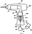
Первый вариант выполнения изобретения будет описан со ссылкой на фиг.1. Электроинструмент 20 имеет основной корпус 20а и корпус 20b рукоятки. Двигатель 21 закреплен в основном корпусе 20а, и блок управления 22, включающий схему управления двигателя, закреплен в корпусе 20b рукоятки. Кнопка 23 включения электрически связана с блоком 22 управления и подает на него сигналы, тем самым начиная или останавливая работу электроинструмента 20. Двигатель 21 представляет собой, например, бесщеточный двигатель постоянного тока, и движущая сила передается от двигателя 21 через механизм передачи движущей силы (не показан) к рабочему органу 24. Рабочий орган 24 разъемно соединен с основным корпусом 20а так, что выступает от одного края (конца) основного корпуса 20а, и выполнен в данном примере в виде инструмента для закручивания винтов.A first embodiment of the invention will be described with reference to FIG. The
Блок 30 топливного элемента (топливной батареи) представляет собой узел, выполненный, например, из пластика и входящий в укладочный кейс, корпус 31 топливного элемента (топливной батареи), конструкция которого описана выше, и топливный картридж 32, из которого в корпус 31 топливного элемента подается топливо, например водный раствор метанола. Корпус 31 топливного элемента снабжен спаренными выходными контактами 31а и 31b и входным топливным патрубком 31с. Топливный картридж 32 имеет конструкцию, при которой он может быть разъемно соединен с корпусом 31 топливного элемента. При присоединении топливного картриджа 32 к корпусу 31 топливного элемента подающий патрубок 32а топливного картриджа 32 вводится во входной патрубок 31с корпуса 31 топливного элемента, так что топливо поступает из топливного картриджа 32 в корпус 31 топливного элемента. При такой компоновке с корпуса 31 топливного элемента можно снимать электрическую энергию, используя топливо, поступающее из топливного картриджа 32.The
При этом блок 30 топливного элемента, представляющий собой комбинацию корпуса 31 топливного элемента и топливного картриджа 32, устроен так, что узел топливных элементов может быть разъемно скреплен с нижним торцом корпуса 20b рукоятки электроинструмента 20. То есть блок 30 топливного элемента может быть разъемно соединен с корпусом 20 электроинструмента. Если блок 30 топливного элемента соединен с нижним торцом корпуса 20b рукоятки, то спаренные выходные контакты 31а и 31b корпуса 31 топливного элемента имеют такую конструкцию, что эти спаренные выходные контакты электрически соединяются со спаренными входными контактами 22а и 22b блока 22 управления. При такой компоновке электрическая энергия, возникающая на спаренных контактах 31а и 31b корпуса 31 топливного элемента, подается через спаренные входные контакты 22а и 22b на блок 22 управления, при этом эта полученная электрическая энергия может быть использована как источник движущей силы для двигателя 21 электроинструмента 20.In this case, the
В соответствии с описанной выше компоновкой пользователи вместе с электроинструментом 20 могут взять с собой на рабочее место запасной топливный картридж 32, и, когда закончится топливо в топливном картридже 32, используемом ими, они могут не прерывать работы, заменив картридж на новый, запасной топливный картридж 32. В этом случае замена топливного картриджа 32 может быть выполнена за короткое время в последовательности, при которой сначала отсоединяют блок 30 топливного элемента от электроинструмента 20 и отделяют топливный картридж 32 от блока 30 топливного элемента, уже отсоединенного от электроинструмента 20. Измеритель уровня топлива для контроля его количества может быть предусмотрен или в корпусе 31 топливного элемента, или в топливном картридже 32.In accordance with the arrangement described above, users, together with the
В описанной выше компоновке электроинструмент 20 можно использовать длительное время даже на рабочем месте, где нет ни силовой установки, такой как промышленный источник питания, ни возможности подключения зарядного устройства.In the above arrangement, the
Вариант 2Option 2
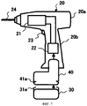
На фиг.2 схематически представлен второй вариант выполнения изобретения. Аналогично первому варианту, описанному выше, блок 30 топливного элемента имеет конструкцию, при которой он может быть разъемно соединен с нижним торцом корпуса 20b рукоятки электроинструмента 20.Figure 2 schematically shows a second embodiment of the invention. Similar to the first embodiment described above, the
Блок 30 топливного элемента отличается от первого варианта выполнения тем, что в блоке по второму варианту выполнения используется топливный бачок 33 вместо одноразового топливного картриджа 32 (фиг.1). В соответствии со своей конструкцией топливный бачок 33 соединен с входным патрубком 31с корпуса 31 топливного элемента для подачи топлива, находящегося в топливном бачке 33, в корпус 31 топливного элемента. Топливный бачок 33 имеет конструкцию, в которой, если указатель заполнения (не показан) топливного бачка 33 показывает снижение содержания топлива в топливном бачке 33, топливо можно добавить или восстановить из топливоподатчика 35 через входной патрубок 34 топливного бачка. При такой компоновке в корпусе 31 топливного элемента может вырабатываться электрическая энергия, и полученная электрическая энергия может быть использована как источник движущей силы двигателя 21 электроинструмента 20.The
Согласно этому варианту выполнения, так как топливный бачок 33, размещенный в блоке 30 топливного элемента, имеет конструкцию, при которой топливо можно подавать снаружи, пользователи могут принести с собой на рабочее место топливоподатчик 35, заполненный топливом, и работать с электроинструментом длительное время.According to this embodiment, since the
Вариант 3Option 3
На фиг.3 схематически представлен третий вариант выполнения изобретения. В основном блок 30 топливного элемента имеет такую же конструкцию, как во втором варианте выполнения, в которой он может быть разъемно соединен с корпусом 20b рукоятки электроинструмента 20. В узле 30 топливного элемента используется топливный бачок 33, соединенный с входным патрубком 31с корпуса 31 топливного элемента. Топливный бачок 33 имеет конструкцию, при которой топливо можно пополнять из топливоподатчика 35 через входной патрубок 34 топливного бачка 33. В соответствии со своей конструкцией другое днище топливного бачка 33 связано с входным патрубком 31с корпуса 31 топливного элемента, так что топливо, находящееся в топливном бачке 33, может быть подано в корпус 31 топливного элемента. При такой компоновке в корпусе 31 топливного элемента может вырабатываться электрическая энергия, и полученная электрическая энергия может быть использована как источник движущей силы электроинструмента 20.Figure 3 schematically shows a third embodiment of the invention. Basically, the
В описанной выше компоновке, если есть необходимость в подаче топлива в топливный бачок 33 снаружи, узел 30 топливного элемента, разъемно скрепленный с корпусом 20b рукоятки, сначала отсоединяют от корпуса 20b рукоятки и затем подают топливо из топливоподатчика 35 через входной патрубок 34 топливного бачка 33 блока 30 топливного элемента.In the above arrangement, if there is a need to supply fuel to the
Вариант 4Option 4
На фиг.4 схематически представлен четвертый вариант выполнения изобретения. Электроинструмент 20 включает двигатель 21, размещенный в основном корпусе 20а, блок 22 управления, размещенный в корпусе 20b рукоятки и регулирующий работу двигателя 21, и корпус 31 топливного элемента. То есть корпус 31 топливного элемента введен внутрь электроинструмента 20.4 schematically shows a fourth embodiment of the invention. The
При этом топливный картридж 32, заполненный топливом, например водным раствором метанола, разъемно соединен с корпусом 31 топливного элемента и имеет подающий патрубок 32а, выполненный с возможностью отсоединения от входного патрубка 31с корпуса 31 топливного элемента. В такой компоновке топливо, находящееся в топливном картридже 32, подается в корпус 31 топливного элемента, и в корпусе 31 топливного элемента может вырабатываться электрическая энергия. Полученная электрическая энергия используется как источник движущей силы электроинструмента 20.In this case, the
Если в процессе использования электроинструмента 20 количество топлива в корпусе 31 топливного элемента снижается, пользователи могут заменить топливный картридж 32 новым топливным картриджем.If the amount of fuel in the
Вариант 5Option 5
На фиг.5 схематически представлен пятый вариант выполнения изобретения. Аналогично четвертому варианту выполнения, описанному выше, электроинструмент 20 включает двигатель 21, размещенный в основном корпусе 20а, блок 22 управления, размещенный в корпусе 20b рукоятки и регулирующий работу двигателя 21, и корпус 31 топливного элемента.5 schematically shows a fifth embodiment of the invention. Similarly to the fourth embodiment described above, the
При этом вместо топливного картриджа 32 (смотри фиг.4), применяемого в четвертом варианте выполнения, используется топливный бачок 33, заполненный топливом, таким как водный раствор метанола. Топливный бачок 33 разъемно скреплен с корпусом 31 топливного элемента и имеет подающий патрубок 33а, выполненный с возможностью отсоединения от входного патрубка 31с корпуса 31 топливного элемента. То есть топливный бачок 33 выполнен так, чтобы его можно было отсоединить от корпуса 31, введенного внутрь электроинструмента 20. Кроме того топливный бачок 33 имеет конструкцию, при которой топливо, содержащееся в топливном бачке 33, может быть подано в корпус 31 топливного элемента. При такой компоновке в корпусе 31 топливного элемента может вырабатываться электрическая энергия, и полученная электрическая энергия может быть использована как источник движущей силы электроинструмента 20.Moreover, instead of the fuel cartridge 32 (see FIG. 4) used in the fourth embodiment, a
Если при работе с электроинструментом 20 содержание топлива снижается, пользователи могут пополнить или восстановить количество топлива из топливоподатчика 35, наполняя топливо через входной патрубок 34 топливного бачка 33.If the fuel content is reduced when working with the
Вариант 6Option 6
На фиг.7 схематически представлена структурная схема беспроводного электроинструмента, выполненного в соответствии с шестым вариантом изобретения, а на фиг.8 показана функциональная блок-схема беспроводного электроинструмента с фиг.7. В этом варианте выполнения представлен так называемый гибридный беспроводной электроинструмент, в котором в качестве источника электрической энергии для двигателя 21 используется как блок вторичной батареи (аккумуляторный блок), в котором применен обычный литий-ионный аккумулятор, так и описанный выше топливный элемент 30. Здесь под блоком 40 вторичной батареи подразумевается узел вторичного аккумулятора 41 (смотри фиг.8) и узел, включающий схему 42 защиты (смотри фиг.8), электрически связанную со вторичным аккумулятором 41. Схема 42 защиты, в частности, используется для литий-ионного аккумулятора 41, то есть является схемой, включающей внутреннюю защиту, в соответствии с предшествующим уровнем техники предусматривающую предотвращение избыточной зарядки и избыточной разрядки литий-ионного аккумулятора 41 или защиту от повреждения аккумулятора, вызванного броском тока.FIG. 7 schematically shows a block diagram of a wireless power tool made in accordance with a sixth embodiment of the invention, and FIG. 8 shows a functional block diagram of a wireless power tool of FIG. 7. In this embodiment, a so-called hybrid wireless power tool is presented in which both the secondary battery unit (battery pack) using the conventional lithium-ion battery and the
Блок 40 вторичной батареи может представлять собой вторичные батареи другого типа, отличного от литий-ионного, такие как никель-кадмиевые или никель-водородные аккумуляторы.The
Блок 40 вторичной батареи разъемно связан с корпусом 20 электроинструмента, а блок 30 топливного элемента разъемно соединен и электрически связан с блоком 40 вторичной батареи на нижней торцевой поверхности последнего. В качестве механизма соединения/отделения блока 40 вторичной батареи и корпуса 20 электроинструмента аналогично предшествующему уровню техники может быть использована конструкция, в которой имеется стопорный элемент на стороне блока 40 вторичной батареи и фиксирующий паз, взаимодействующий со стопорным элементом, на стороне корпуса 20 электроинструмента. В качестве механизма соединения/отделения блока 40 вторичной батареи и блока 30 топливного элемента может быть использован известный ранее механизм сцепления, в котором на одной из соединяемых частей введен упругий стопорный элемент (захват) 31е, а на другой соединяемой части выполнен фиксирующий паз (паз, входящий в зацепление) 41а, с которым взаимодействует стопорный элемент. Кроме того, в первом варианте выполнения и в других близких вариантах введен стопорный элемент на стороне блока топливных элементов и фиксирующий паз на стороне корпуса электроинструмента, что дает возможность разъемно соединять топливный элемент с корпусом электроинструмента.The
Аналогично описанным выше вариантам выполнения блок 30 топливного элемента содержит корпус 31 топливного элемента и топливный контейнер 36 (контейнер, содержащий топливный картридж 32 и топливный бачок 33). Блок 30 топливного элемента содержит также схему 37 контроля зарядки вторичной батареи 41 блока 40 вторичной батареи. В этом варианте выполнения схема 37 контроля зарядки встроена в блок 30 топливного элемента, однако она может быть введена в блок 40 вторичной батареи или может быть оформлена в виде отдельного блока. Так как блок 30 топливного элемента разъемно связан с нижним торцом блока 40 вторичной батареи, оператору неудобно захватывать электроинструмент 20 и сохранять возможность работы с электроинструментом без отличия в балансировке его веса от обычного электроинструмента. Схема 37 контроля зарядки электрически включена между блоком 40 вторичной батареи и блоком 30 топливного элемента. Соответственно, если выходное напряжение блока 40 вторичной батареи падет и работа электродвигателя 21 остановлена, схема 37 контроля зарядки переключает блок 30 топливного элемента на зарядку блока 40 вторичной батареи. Эта операция описана ниже.Similarly to the embodiments described above, the
Если электродвигатель 21 работает, как показано на фиг.8, блок 40 служит приводным источником энергии для двигателя 21 и подает электрическую энергию непосредственно на блок 22 управления двигателя, включающий схему управления двигателя. Поэтому, если выключатель 23а питания, связанный с кнопкой 23 включения, запущен, то схема 26 регистрации включения определяет состояние выключателя 23а питания и направляет выходной сигнал на схему 37 контроля зарядки. Тогда блок 40 вторичной батареи подает энергию на схему 22 управления двигателя для приведение в действие двигателя 21.If the
При остановке работы электродвигателя 21 выключатель 23а переходит в выключенное состояние. Схема 26 регистрации включения регистрирует выключенное состояние выключателя 23а и выдает выходной сигнал об отключении на схему 37 контроля зарядки. По полученному сигналу схема 37 контроля зарядки переключает блок 30 топливного элемента на зарядку блока 41 вторичной батареи. То есть блок 30 топливного элемента работает как зарядное устройство, подающее электрическую энергию вторичной батарее 41, если работа электроинструмента 20 приостановлена. На пути зарядного тока введен однонаправленный диод 43, направление пропускания которого совпадает с направлением зарядного тока. Если напряжение вторичной батареи 41 превышает напряжение на топливном элементе блока 30 или если напряжение на топливном элементе падает, диод перекрывает путь зарядки, так что блок 30 топливного элемента не может действовать как нагрузка блока 41 вторичной батареи.When the
В соответствии с шестым вариантом выполнения, имеющим такую компоновку, электроинструмент 20, потребляющий относительно большой ток нагрузки, получает электрическую энергию от имеющей большую мощность литий-ионной вторичной батареи 41, и вторичная батарея 41, хранящая потребляемую электрическую энергию, пополняется электрической энергией от топливного элемента (блока) 30. Появляется возможность продлить время работы беспроводного электроинструмента на таком рабочем месте, где отсутствует подача промышленного электропитания.According to a sixth embodiment having such an arrangement, a
Для упрощения зарядки вторичной батареи 40 или пополнения топливных элементов 30 шестой вариант выполнения может быть модифицирован в соответствии с нижеследующими изменениями.To simplify charging the
(1) Вторичная батарея 40 может быть разъемно связана с корпусом 20 электроинструмента, и топливный элемент 30 может быть разъемно связана со вторичной батареей 40. В такой компоновке вторичную батарею 40 можно заряжать от промышленного блока питания переменного тока через зарядное устройство (не показано). Кроме того, может быть упрощена замена топливного контейнера 36 топливного элемента 30.(1) The
(2) Вторичная батарея 40 и топливный элемент 30 могут быть объединены в выполненный с возможностью подсоединения узел, и эта собранная конструкция (40 и 30) может быть разъемно связана с корпусом 20 электроинструмента.(2) The
(3) Топливный контейнер 36 топливного элемента 30 может быть разъемно связан с корпусом 31 топливного элемента аналогично тому, что описано выше.(3) The
(4) Хотя схема 37 контроля зарядки электрически включена между топливным элементом 30 и вторичной батареей 40, чтобы обеспечить возможность зарядки вторичной батареи 40 от топливных элементов 30, топливный элемент 30 может быть электрически связан со схемой 37 контроля зарядки и разъемно скреплена со вторичной батареей 40.(4) Although the
(5) Так как схема 42 защиты блока 40 вторичной батареи регистрирует избыточную зарядку и избыточную разрядку блока вторичной батареи, то, если схема 42 защиты определяет, что литий-ионная батарея 41 заряжена избыточно от блока 30 топливного элемента, схема 37 контроля зарядки может получить сигнал о избыточной зарядке от схемы 42 защиты и остановить зарядку. Более того, если схема 42 защиты зарегистрировала избыточную разрядку, блок 40 вторичной батареи может быть заряжен от блока 30 топливного элемента вне зависимости от получения сигнала со схемы 26 регистрации включения. В этом случае электроинструмент 20 может приводиться в действие блоком 30 топливного элемента.(5) Since the
Вариант 7Option 7
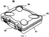
На фигурах 9 и 10 схематически изображен укладочный кейс (футляр), в котором размещается беспроводной электроинструмент, выполненный по настоящему изобретению и описанный выше, для облегчения переноски на рабочее место, и в котором беспроводной электроинструмент сохраняется, когда его не используют. В частности, укладочный кейс 60 пригоден для использования в качестве носимого кейса, предназначенного для доставки беспроводного электроинструмента на рабочее место, где возможность использования промышленного источника переменного тока для зарядки вторичной батареи электроинструмента ограничена, или на рабочее место, где вообще отсутствует оборудование для подачи промышленного переменного тока.Figures 9 and 10 schematically depict a stacking case (case) in which a cordless power tool, made according to the present invention and described above, is placed to facilitate carrying to a workplace, and in which a cordless power tool is stored when not in use. In particular, the laying
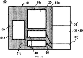
Как показано на фиг.9, кейс 60 для хранения и переноски содержит часть 61 кейса, предназначенную для размещения содержимого (нижняя часть кейса), часть 62 (верхнюю часть кейса), представляющую собой крышку, скрепленную с частью 61 кейса, предназначенной для размещения содержимого, с возможностью открывания на спаренных петлях 63 и 64, и ручку (захват) 65. В соответствии со схемой размещения, представленной на фиг.10, участок укладки части 61 кейса, предназначенной для размещения содержимого кейса, содержит место 61а для укладки корпуса 20 электроинструмента (к которому прикрепляются вторичная батарея 40 и топливный элемент 30), место 61b для укладки запасных вторичной батареи 40 и топливных элементов 30, отделенных от корпуса электроинструмента 20, место 61с для укладки запасных топливных элементов 30 и место 61d для укладки зарядного устройства 50, предназначенного для зарядки вторичной батареи 40 от источника переменного тока.As shown in FIG. 9, the storage and carrying
Как показано на фиг.11, части (части, предназначенные для укладки) с 61а по 61d разделены друг от друга и выполнены в виде углубленных мест или разделенных мест (гнезд), форма которых соответствует наружным очертаниям элементов, размещаемых в них.As shown in FIG. 11, the parts (parts intended for laying) from 61a to 61d are separated from each other and are made in the form of indented places or divided places (nests), the shape of which corresponds to the external outlines of the elements placed in them.
Если корпус 20 электроинструмента и другое содержимое в заданной ориентации размещены в соответствующих укладочных местах с 61а по 61d части 61 кейса, предназначенной для размещения содержимого, и часть 62 крышки закрыта, корпус 20 электроинструмента, батареи 30 и 40 и другие элементы можно переносить без затруднений.If the
В соответствии с данным вариантом выполнения корпус 31 топливного элемента блок 37 со схемой контроля зарядки и топливный контейнер 36, размещенные в укладочной части 61 с, составляют блок зарядки вторичной батареи 40, как показано на фиг.8, и электрически связаны со вторичной батареей 40 через межэлементное соединение 66. В такой компоновке запасная вторичная батарея 40 заряжается при нахождении в кейсе 60, то есть при переноске корпуса электроинструмента или при хранении. В данном варианте предохранительный сигнал (сигнал на отключение) подается со схемы 26 регистрации включения (фиг.8) на контакт входного сигнала блока 37 схемы контроля зарядки. В другом, модифицированном варианте выключатель может быть введен в схему 37 контроля зарядки, и тогда, если блок 40 вторичной батареи находится в укладочном кейсе 60, выключатель может работать, давая возможность заряжать вторичную батарею 40 от топливных элементов 30, даже если кнопка 23 включения не нажата. Кроме того, блок 30 топливного элемента может быть закреплен в кейсе 60 (например, в части 61с на фиг.10), и, если блок 40 вторичной батареи уложен, а межэлементное соединение 66 подсоединено, блок 40 вторичной батареи может заряжаться от топливных элементов 30 автоматически или по ручной команде. В данном варианте топливный контейнер 36 может быть разъемно и с возможностью замены соединен с кейсом 60 для хранения и транспортировки, и топливный бачок может быть установлен таким образом, чтобы происходило пополнение топлива.According to this embodiment, the
В случае укладочного кейса 60, имеющего такую компоновку, на рабочем месте, где имеется оборудование для подачи промышленного переменного тока, вторичная батарея 40 может быть заряжена от зарядного устройства 50 для передачи приводной мощности к электроинструменту 20, в то время как на рабочем месте, где отсутствует оборудование для подачи промышленного переменного тока, вторичная батарея 40 может быть заряжена от топливных элементов 30. Соответственно, имеется возможность приносить беспроводной электроинструмент, пригодный для использования на таком рабочем месте.In the case of a stacking
Как очевидно из рассмотрения вариантов выполнения настоящего изобретения, так как топливный бачок или топливный картридж, предназначенные для хранения или подачи топлива, разъемно соединены с корпусом беспроводного электроинструмента, имеется возможность обеспечивать питание электроинструмента только за счет замены топливного контейнера, включая бачок или картридж. Соответственно, повышается производительность труда. Дополнительно, так как для топливной батареи можно в качестве топлива использовать топливо, не содержащее вредных примесей, появляется возможность решения проблемы загрязнения окружающей среды.As is apparent from consideration of embodiments of the present invention, since the fuel tank or fuel cartridge for storing or supplying fuel is detachably connected to the housing of the cordless power tool, it is possible to provide power to the power tool only by replacing the fuel container, including the tank or cartridge. Accordingly, labor productivity increases. Additionally, since for a fuel battery it is possible to use fuel that does not contain harmful impurities as fuel, it becomes possible to solve the problem of environmental pollution.
К тому же настоящее изобретение может быть применено для беспроводного электроинструмента, в котором используется обычная вторичная батарея, что дает возможность продления срока службы такого инструмента.In addition, the present invention can be applied to a cordless power tool that uses a conventional secondary battery, which makes it possible to extend the life of such a tool.
Выше изобретение данных авторов описано в подробностях в различных его вариантах. Однако настоящее изобретение не ограничено описанными вариантами выполнения, и в него могут быть внесены различные изменения без выхода за объем и сущность настоящего изобретения. Например, в вариантах выполнения изобретения в качестве примера беспроводного электроинструмента описан ударный инструмент, однако настоящее изобретение может быть применено в таком беспроводном электроинструменте, как электрическая ножовочная пила или дисковая пила.Above, the invention of these authors is described in detail in its various versions. However, the present invention is not limited to the described embodiments, and various changes can be made without departing from the scope and essence of the present invention. For example, in embodiments of the invention, a percussion instrument is described as an example of a cordless power tool, however, the present invention can be applied to a cordless power tool such as an electric hacksaw or circular saw.
Claims (17)
Applications Claiming Priority (4)
| Application Number | Priority Date | Filing Date | Title |
|---|---|---|---|
| JP2007-072377 | 2007-03-20 | ||
| JP2007072377 | 2007-03-20 | ||
| JP2008-038515 | 2008-02-20 | ||
| JP2008038515A JP2008260118A (en) | 2007-03-20 | 2008-02-20 | Cordless power tool and its storage case |
Publications (2)
| Publication Number | Publication Date |
|---|---|
| RU2009132709A RU2009132709A (en) | 2011-04-27 |
| RU2464130C2 true RU2464130C2 (en) | 2012-10-20 |
Family
ID=39642740
Family Applications (1)
| Application Number | Title | Priority Date | Filing Date |
|---|---|---|---|
| RU2009132709/02A RU2464130C2 (en) | 2007-03-20 | 2008-03-19 | Wireless electronic tool with fuel cell and case there for |
Country Status (7)
| Country | Link |
|---|---|
| EP (1) | EP2129497B1 (en) |
| JP (1) | JP2008260118A (en) |
| CN (1) | CN101622106B (en) |
| ES (1) | ES2390989T3 (en) |
| RU (1) | RU2464130C2 (en) |
| TW (1) | TWI339149B (en) |
| WO (1) | WO2008126685A2 (en) |
Families Citing this family (14)
| Publication number | Priority date | Publication date | Assignee | Title |
|---|---|---|---|---|
| DE102009029537A1 (en) | 2009-09-17 | 2011-03-31 | Robert Bosch Gmbh | Hand tool module |
| JP5431975B2 (en) * | 2010-01-07 | 2014-03-05 | 株式会社マキタ | Electric tool |
| JP5491244B2 (en) * | 2010-03-23 | 2014-05-14 | 株式会社マキタ | Electric tool |
| JP2011212792A (en) * | 2010-03-31 | 2011-10-27 | Makita Corp | Electric power tool |
| JP5756104B2 (en) * | 2010-06-23 | 2015-07-29 | 株式会社マキタ | Power supply for power tools |
| SE535458C2 (en) * | 2010-09-30 | 2012-08-14 | Atlas Copco Tools Ab | Portable electric tool with a backup voltage accumulator |
| DE102011086884A1 (en) * | 2011-11-22 | 2013-05-23 | Robert Bosch Gmbh | Hand tool box |
| EP3730061B1 (en) | 2011-12-16 | 2024-04-10 | Stryker Corporation | A cassette configured for use with a medical waste collection system |
| CN103009324A (en) * | 2012-11-22 | 2013-04-03 | 浙江明磊工具实业有限公司 | Rechargeable screwdriver |
| CN105529970B (en) * | 2014-09-30 | 2018-10-12 | 南京德朔实业有限公司 | Electric tool |
| WO2016069830A2 (en) | 2014-10-30 | 2016-05-06 | Stryker Far East, Inc. | Surgical tool with an aseptic power module that enters a specific operating state based on the type of handpiece to which the module is attached |
| CN109108334A (en) * | 2017-02-20 | 2019-01-01 | 韦秀方 | A kind of Portable Automatic drilling machine |
| CN107717826A (en) * | 2017-11-30 | 2018-02-23 | 郑州小动电子科技有限公司 | A kind of electric screwdriver component and screwdriver bit box |
| CN114346951A (en) * | 2021-12-02 | 2022-04-15 | 国网浙江省电力有限公司金华供电公司 | Electric tool for disassembling and assembling bolt |
Citations (5)
| Publication number | Priority date | Publication date | Assignee | Title |
|---|---|---|---|---|
| RU6775U1 (en) * | 1996-10-10 | 1998-06-16 | Акционерное общество открытого типа "Контур" | CASE FOR TOOL SET |
| RU2146193C1 (en) * | 1998-10-29 | 2000-03-10 | ООО Научно-производственная фирма "КУЛОН" | Portable electrically driven tool |
| US6104162A (en) * | 1999-09-11 | 2000-08-15 | Sainsbury; Simon R. | Method and apparatus for multi-power source for power tools |
| DE202006015385U1 (en) * | 2006-10-07 | 2006-11-30 | Metabowerke Gmbh | Electrical hand tool unit has cell holder receiving accumulator module that is reversibly attached by catches with the holder acting as a cover |
| DE202006017538U1 (en) * | 2006-11-15 | 2007-01-18 | Hsieh, Chih-Ching | Power drill has handgrip and drive powered by electricity or compressed air and water collector feeding fuel cell that generates electricity for drive |
Family Cites Families (6)
| Publication number | Priority date | Publication date | Assignee | Title |
|---|---|---|---|---|
| JP4028603B2 (en) * | 1996-02-05 | 2007-12-26 | 松下電器産業株式会社 | Fuel cell device for equipment |
| JP4042101B2 (en) * | 2001-07-06 | 2008-02-06 | ソニー株式会社 | FUEL CELL AND POWER SUPPLY METHOD USING FUEL CELL |
| DE10132831A1 (en) * | 2001-07-06 | 2003-01-16 | Bosch Gmbh Robert | Case with a receptacle for a battery-operated power tool and case system with at least two such cases |
| ATE403944T1 (en) * | 2002-03-05 | 2008-08-15 | Sfc Smart Fuel Cell Ag | MOBILE DEVICE FOR SUPPLYING ENERGY WITH FUEL CELLS |
| JP4193521B2 (en) * | 2002-03-20 | 2008-12-10 | ソニー株式会社 | FUEL CELL DEVICE AND FUEL CELL CONTROL METHOD |
| JP2006049175A (en) * | 2004-08-06 | 2006-02-16 | Sanyo Electric Co Ltd | Fuel cell system |
-
2008
- 2008-02-20 JP JP2008038515A patent/JP2008260118A/en active Pending
- 2008-03-19 WO PCT/JP2008/055812 patent/WO2008126685A2/en active Application Filing
- 2008-03-19 EP EP08722896A patent/EP2129497B1/en not_active Not-in-force
- 2008-03-19 ES ES08722896T patent/ES2390989T3/en active Active
- 2008-03-19 RU RU2009132709/02A patent/RU2464130C2/en not_active IP Right Cessation
- 2008-03-19 CN CN2008800068079A patent/CN101622106B/en not_active Expired - Fee Related
- 2008-03-20 TW TW097109940A patent/TWI339149B/en not_active IP Right Cessation
Patent Citations (5)
| Publication number | Priority date | Publication date | Assignee | Title |
|---|---|---|---|---|
| RU6775U1 (en) * | 1996-10-10 | 1998-06-16 | Акционерное общество открытого типа "Контур" | CASE FOR TOOL SET |
| RU2146193C1 (en) * | 1998-10-29 | 2000-03-10 | ООО Научно-производственная фирма "КУЛОН" | Portable electrically driven tool |
| US6104162A (en) * | 1999-09-11 | 2000-08-15 | Sainsbury; Simon R. | Method and apparatus for multi-power source for power tools |
| DE202006015385U1 (en) * | 2006-10-07 | 2006-11-30 | Metabowerke Gmbh | Electrical hand tool unit has cell holder receiving accumulator module that is reversibly attached by catches with the holder acting as a cover |
| DE202006017538U1 (en) * | 2006-11-15 | 2007-01-18 | Hsieh, Chih-Ching | Power drill has handgrip and drive powered by electricity or compressed air and water collector feeding fuel cell that generates electricity for drive |
Also Published As
| Publication number | Publication date |
|---|---|
| CN101622106A (en) | 2010-01-06 |
| EP2129497A2 (en) | 2009-12-09 |
| TW200902243A (en) | 2009-01-16 |
| JP2008260118A (en) | 2008-10-30 |
| CN101622106B (en) | 2013-03-06 |
| EP2129497B1 (en) | 2012-07-04 |
| WO2008126685A3 (en) | 2009-02-19 |
| WO2008126685A2 (en) | 2008-10-23 |
| ES2390989T3 (en) | 2012-11-20 |
| TWI339149B (en) | 2011-03-21 |
| RU2009132709A (en) | 2011-04-27 |
Similar Documents
| Publication | Publication Date | Title |
|---|---|---|
| RU2464130C2 (en) | Wireless electronic tool with fuel cell and case there for | |
| US9819203B2 (en) | Electric power tool system | |
| US20100065295A1 (en) | Cordless power tool and accomodation case | |
| CN102452069B (en) | Electric tool system | |
| US8384340B2 (en) | Electrical appliance that utilizes multiple power sources | |
| US7781902B2 (en) | Generator systems and methods | |
| US20080079264A1 (en) | Power-generating apparatus, such as a generator | |
| US20090096399A1 (en) | Intelligent motorized appliances with multiple power sources | |
| JP4488381B2 (en) | Battery pack system | |
| EP1559151A1 (en) | Battery pack equipped with detachable rechargeable battery and portable electronic device equipped with the battery pack | |
| KR101204118B1 (en) | Method and Apparatus of Power Control | |
| JP5027489B2 (en) | Power tool case | |
| WO2024174838A1 (en) | Sodium ion battery, charger thereof, energy storage device, and electric tool | |
| CN116388314A (en) | Electrical appliance with multiple electromechanical battery interfaces | |
| TH38232A3 (en) | A battery with a built-in controller for extended service uptime. |
Legal Events
| Date | Code | Title | Description |
|---|---|---|---|
| MM4A | The patent is invalid due to non-payment of fees |
Effective date: 20150320 |