RU2464083C2 - Gas distribution grate for polymeriser - Google Patents
Gas distribution grate for polymeriser Download PDFInfo
- Publication number
- RU2464083C2 RU2464083C2 RU2009127726/02A RU2009127726A RU2464083C2 RU 2464083 C2 RU2464083 C2 RU 2464083C2 RU 2009127726/02 A RU2009127726/02 A RU 2009127726/02A RU 2009127726 A RU2009127726 A RU 2009127726A RU 2464083 C2 RU2464083 C2 RU 2464083C2
- Authority
- RU
- Russia
- Prior art keywords
- gas
- trays
- grooves
- reactor
- gas distribution
- Prior art date
Links
Images
Classifications
-
- B—PERFORMING OPERATIONS; TRANSPORTING
- B01—PHYSICAL OR CHEMICAL PROCESSES OR APPARATUS IN GENERAL
- B01J—CHEMICAL OR PHYSICAL PROCESSES, e.g. CATALYSIS OR COLLOID CHEMISTRY; THEIR RELEVANT APPARATUS
- B01J8/00—Chemical or physical processes in general, conducted in the presence of fluids and solid particles; Apparatus for such processes
- B01J8/18—Chemical or physical processes in general, conducted in the presence of fluids and solid particles; Apparatus for such processes with fluidised particles
- B01J8/1818—Feeding of the fluidising gas
- B01J8/1827—Feeding of the fluidising gas the fluidising gas being a reactant
-
- B—PERFORMING OPERATIONS; TRANSPORTING
- B01—PHYSICAL OR CHEMICAL PROCESSES OR APPARATUS IN GENERAL
- B01J—CHEMICAL OR PHYSICAL PROCESSES, e.g. CATALYSIS OR COLLOID CHEMISTRY; THEIR RELEVANT APPARATUS
- B01J8/00—Chemical or physical processes in general, conducted in the presence of fluids and solid particles; Apparatus for such processes
- B01J8/18—Chemical or physical processes in general, conducted in the presence of fluids and solid particles; Apparatus for such processes with fluidised particles
- B01J8/24—Chemical or physical processes in general, conducted in the presence of fluids and solid particles; Apparatus for such processes with fluidised particles according to "fluidised-bed" technique
-
- B—PERFORMING OPERATIONS; TRANSPORTING
- B01—PHYSICAL OR CHEMICAL PROCESSES OR APPARATUS IN GENERAL
- B01J—CHEMICAL OR PHYSICAL PROCESSES, e.g. CATALYSIS OR COLLOID CHEMISTRY; THEIR RELEVANT APPARATUS
- B01J8/00—Chemical or physical processes in general, conducted in the presence of fluids and solid particles; Apparatus for such processes
- B01J8/18—Chemical or physical processes in general, conducted in the presence of fluids and solid particles; Apparatus for such processes with fluidised particles
- B01J8/1818—Feeding of the fluidising gas
-
- C—CHEMISTRY; METALLURGY
- C08—ORGANIC MACROMOLECULAR COMPOUNDS; THEIR PREPARATION OR CHEMICAL WORKING-UP; COMPOSITIONS BASED THEREON
- C08F—MACROMOLECULAR COMPOUNDS OBTAINED BY REACTIONS ONLY INVOLVING CARBON-TO-CARBON UNSATURATED BONDS
- C08F10/00—Homopolymers and copolymers of unsaturated aliphatic hydrocarbons having only one carbon-to-carbon double bond
-
- B—PERFORMING OPERATIONS; TRANSPORTING
- B01—PHYSICAL OR CHEMICAL PROCESSES OR APPARATUS IN GENERAL
- B01J—CHEMICAL OR PHYSICAL PROCESSES, e.g. CATALYSIS OR COLLOID CHEMISTRY; THEIR RELEVANT APPARATUS
- B01J2219/00—Chemical, physical or physico-chemical processes in general; Their relevant apparatus
- B01J2219/00049—Controlling or regulating processes
- B01J2219/00245—Avoiding undesirable reactions or side-effects
- B01J2219/00247—Fouling of the reactor or the process equipment
Landscapes
- Chemical & Material Sciences (AREA)
- Chemical Kinetics & Catalysis (AREA)
- Organic Chemistry (AREA)
- Engineering & Computer Science (AREA)
- Combustion & Propulsion (AREA)
- Health & Medical Sciences (AREA)
- Medicinal Chemistry (AREA)
- Polymers & Plastics (AREA)
- Polymerisation Methods In General (AREA)
- Gas Separation By Absorption (AREA)
Abstract
Description
Настоящее изобретение относится к газораспределительной решетке, пригодной для распределения восходящего потока газа в резервуаре с полимером в псевдоожиженном состоянии.The present invention relates to a gas distribution grid suitable for distributing an upward flow of gas in a fluidized polymer tank.
В частности, настоящее изобретение относится к газораспределительной решетке, пригодной для установки в реакторе с псевдоожиженным слоем для полимеризации олефинов. Настоящее изобретение также относится к реактору с псевдоожиженным слоем, включающему указанную распределительную решетку, и к способу газофазной полимеризации, осуществляемому в таком реакторе с псевдоожиженным слоем.In particular, the present invention relates to a gas distribution grid suitable for installation in a fluidized bed reactor for the polymerization of olefins. The present invention also relates to a fluidized bed reactor including said distribution grid, and to a gas phase polymerization process carried out in such a fluidized bed reactor.
Создание катализаторов с высокой активностью и селективностью типа Циглера-Натта и, недавно, металлоценового типа привело к широкому использованию в промышленном масштабе процессов, в которых полимеризацию олефинов осуществляют в газообразной среде в присутствии твердого катализатора. В одном из таких процессов газофазной полимеризации используется реактор с псевдоожиженным слоем, в котором слой частиц полимера поддерживают в псевдоожиженном состоянии при помощи восходящего потока ожижающего газа.The creation of catalysts with high activity and selectivity of the Ziegler-Natta type and, more recently, the metallocene type has led to widespread use on an industrial scale of processes in which the polymerization of olefins is carried out in a gaseous medium in the presence of a solid catalyst. In one such gas phase polymerization process, a fluidized bed reactor is used in which a layer of polymer particles is maintained in a fluidized state using an upward flow of fluidizing gas.
В ходе полимеризации полимер образуется в результате каталитической полимеризации мономеров, его отводят из реактора с целью поддержания постоянного объема слоя полимера. Псевдоожиженный слой, образованный увеличивающимися частицами полимера и частицами катализатора, поддерживают в псевдоожиженном состоянии непрерывной подачи восходящего потока ожижающего газа, который содержит поток рециркулируемого газа и вновь подаваемые мономеры.During the polymerization, the polymer is formed as a result of the catalytic polymerization of monomers, it is withdrawn from the reactor in order to maintain a constant volume of the polymer layer. The fluidized bed formed by the increasing polymer particles and catalyst particles is maintained in a fluidized state by continuously supplying an upward flow of a fluidizing gas that contains a recycle gas stream and newly supplied monomers.
Псевдоожижение порошкообразной твердой фазы представляет собой операцию, которую, как правило, легко осуществить путем подбора скорости потока газа в соответствии с размером, формой и плотностью порошкообразной твердой фазы. Желательно достичь гомогенного распределения ожижающего газа в слое псевдоожиженной твердой фазы. В промышленности для распределения ожижающего газа в слое полимера используют распределительную решетку, причем решетка также выполняет функцию опоры для слоя, когда подача газа прекращена. Как правило, указанная распределительная решетка снабжена отверстиями и устанавливается в нижней части реактора с псевдоожиженным слоем.Fluidization of a powdered solid phase is an operation that is usually easy to carry out by selecting the gas flow rate in accordance with the size, shape and density of the powdered solid phase. It is desirable to achieve a homogeneous distribution of the fluidizing gas in the bed of the fluidized solid phase. In industry, a distribution grid is used to distribute fluidizing gas in a polymer layer, the grid also serving as a support for the layer when gas is shut off. Typically, the specified distribution grid is provided with holes and is installed in the lower part of the fluidized bed reactor.
Наиболее часто употребляемые на установках по полимеризации решетки для создания псевдоожиженного слоя имеют форму цилиндрического диска, который перфорирован множеством сквозных отверстий, позволяющих ожижающему газу поступать из зоны под решеткой в слой псевдоожиженного полимера. Указанная решетка для создания псевдоожиженного слоя также может составлять неотъемлемую часть стенок реактора.The lattices most commonly used in polymerization plants for creating a fluidized bed are in the form of a cylindrical disk, which is perforated with a plurality of through holes that allow fluidizing gas to flow from the zone under the lattice into the fluidized polymer layer. The specified lattice for creating a fluidized bed can also form an integral part of the walls of the reactor.
Однако отмечено, что когда размер реактора с псевдоожиженным слоем превосходит определенную величину, распределение ожижающего газа в слое полимера имеет тенденцию становиться менее гомогенным, так что в слое появляются плотные, плохо ожиженные области, особенно вблизи стенок реактора. Полимеризация олефинов является экзотермической реакцией, в слое полимера могут образовываться локализованные участки с высокой температурой, что приводит к размягчению частиц полимера и их слипанию. Это явление становится все более значимым, когда полимеризацию осуществляют в так называемом «конденсатном режиме», при условии, что ожижающий газ также содержит небольшое количество конденсированных мономеров: недостаточная гомогенность распределения этой жидкости может вызвать адгезию или слипание твердой фазы псевдоожиженного слоя.However, it is noted that when the size of the fluidized bed reactor exceeds a certain value, the distribution of the fluidizing gas in the polymer layer tends to become less homogeneous, so that dense, poorly fluidized areas appear in the layer, especially near the walls of the reactor. The polymerization of olefins is an exothermic reaction, localized areas with a high temperature can form in the polymer layer, which leads to softening of the polymer particles and their adhesion. This phenomenon becomes more and more significant when the polymerization is carried out in the so-called "condensate mode", provided that the fluidizing gas also contains a small amount of condensed monomers: insufficient homogeneity of the distribution of this liquid can cause adhesion or adhesion of the solid phase of the fluidized bed.
Еще один недостаток, связанный с перфорированными решетками известного уровня техники, заключается в том, что сквозные отверстия с большой вероятностью закупориваются в результате осаждения частиц полимера, поэтому реактор полимеризации не может эксплуатироваться непрерывно в течение длительного периода времени. Если отверстия имеют большой размер, проблема закупорки в некоторой степени решается, но тогда некоторые частицы полимера могут падать сквозь эти отверстия в зону под решеткой и образовывать отложения на стенках ниже распределительной пластины. В качестве альтернативы, если увеличивать расстояние между отверстиями, то есть шаг, вероятно образование между отверстиями областей замедленного потока, следовательно, имеющих повышенную температуру, и сгустков полимера в зонах между отверстиями.Another disadvantage associated with perforated gratings of the prior art is that through holes are very likely to become clogged as a result of the deposition of polymer particles, therefore, the polymerization reactor cannot be operated continuously for a long period of time. If the holes are large, the clogging problem is to some extent solved, but then some polymer particles can fall through these holes into the area under the grate and form deposits on the walls below the distribution plate. Alternatively, if you increase the distance between the holes, that is, the step, it is likely the formation between the holes of areas of slow flow, therefore, having an elevated temperature, and polymer clots in the zones between the holes.
Для решения перечисленных выше проблем были предложены решетки для создания псевдоожиженного слоя с отверстиями различной формы, размера, количества и расположения.To solve the above problems, lattices have been proposed for creating a fluidized bed with holes of various shapes, sizes, quantities and locations.
Газораспределительная пластина, снабженная колпачками над отверстиями решетки, предлагается в некоторых патентах для исключения риска закупоривания отверстий решетки при регулярном осуществлении полимеризации, особенно когда слой полимера падает вниз из-за прекращения подачи ожижающего циркулирующего газа. В документах ЕР-В-088404 и GB 2271721 описаны предназначенные для использования в псевдоожиженном слое распределительные пластины, на которых над отверстиями предусмотрены колпачки, предотвращающие прохождение частиц сквозь отверстия.A gas distribution plate provided with caps over the openings of the lattice is proposed in some patents to eliminate the risk of clogging of the openings of the lattice during regular polymerization, especially when the polymer layer falls down due to interruption in the supply of fluidizing circulating gas. Documents EP-B-088404 and GB 2271721 describe distribution plates for use in a fluidized bed, on which caps are provided above the holes to prevent particles from passing through the holes.
В патентной публикации Японии 42404/1992 описана газораспределительная пластина, на которой над отверстиями для прохождения газа расположены накладные колпачки в форме крыши: газ выходит с обеих сторон колпачка. Кроме того, в патентной публикации Японии 284509/1989 описана газораспределительная пластина, накладные колпачки на которой имеют такую форму, что на вертикальном сечении наружная линия идет вверх наклонно, так чтобы отверстия, через которые проходит газ, были накрыты и защищены.Japanese Patent Publication No. 42404/1992 describes a gas distribution plate on which overhead caps in the shape of a roof are located above the gas passage openings: gas exits from both sides of the cap. In addition, Japanese Patent Publication No. 284509/1989 describes a gas distribution plate on which the cover caps are shaped so that the vertical line extends obliquely upward so that the openings through which the gas passes are covered and protected.
Упоминаемые выше распределительные пластины, снабженные колпачками, в некоторой степени помогают избежать закупорки отверстий твердой фазой, однако не могут равномерно распределить поток газа в слое полимера, поэтому они представляют собой неудовлетворительное решение с точки зрения эффективности осуществления процесса полимеризации в псевдоожиженном слое.The distribution plates provided with caps mentioned above help to some extent to avoid plugging the holes with the solid phase, however, they cannot evenly distribute the gas flow in the polymer layer, therefore, they represent an unsatisfactory solution in terms of the efficiency of the polymerization process in the fluidized bed.
В ЕР 173261 предлагается помещать распределительную пластину в нижнем конце реактора с псевдоожиженным слоем соответственно трубопроводу, по которому подводится циркулирующий поток газа. Указанная распределительная пластина позволяет повысить однородность потока газа, проходящего сквозь решетку для создания псевдоожиженного слоя, вызывая возникновение турбулентного потока в области под решеткой для создания псевдоожиженного слоя. Конструкция указанной распределительной пластины такова, что поток газа разделяется на два основных течения, из которых первый направляется вверх, а второй в сторону. Однако описанный вариант осуществления изобретения имеет недостаток, заключающийся в том, что плоские поверхности этой распределительной пластины имеют свойство собирать тонкодисперсные частицы, захваченные потоком циркулирующего газа, поэтому на этих поверхностях распределительной пластины могут вырастать комки полимера, повышающие риск образования препятствий для входа ожижающего газа в реактор полимеризации.In EP 173261, it is proposed to place a distribution plate at the lower end of a fluidized bed reactor, respectively, in a pipe through which a circulating gas stream is supplied. The specified distribution plate allows you to increase the uniformity of the gas flow passing through the grate to create a fluidized bed, causing the appearance of turbulent flow in the area under the grate to create a fluidized bed. The design of the specified distribution plate is such that the gas flow is divided into two main flows, of which the first goes up and the second to the side. However, the described embodiment of the invention has the disadvantage that the flat surfaces of this distribution plate have the ability to collect fine particles trapped by the flow of circulating gas, so polymer lumps can grow on these surfaces of the distribution plate, increasing the risk of obstruction of the fluidizing gas entering the reactor polymerization.
В ЕР 085610 описано газораспределительное устройство для реакторов с псевдоожиженным слоем, состоящее из перевернутого конуса с углом конусности от 50° до 120° и отверстиями на боковых стенках для подвода ожижающего газа. Вершина указанного перевернутого конуса снабжена устройством для выгрузки производимого полимера. Венчик дополнительных прорезей или отверстий в верхнем конце этого конического газораспределительного устройства смещен в сторону, ширина указанных отверстий подобрана так, чтобы через них могли проходить тонкодисперсные частицы, захваченные ожижающим газом, но, в то же время, чтобы было невозможно падение псевдоожиженного слоя под действием силы тяжести при прекращении процесса псевдоожижения. Псевдоожижающий газ перемещается вверх через узкое промежуточное пространство между коническим газораспределительным устройством и стенками реактора. Решетка для создания псевдоожиженного слоя, предлагаемая в ЕР 085610, имеет недостаток, заключающийся в том, что указанное узкое промежуточное пространство, обеспечивающее подвод ожижающего газа, может легко закупориваться тонкодисперсными частицами, захваченными циркулирующим газообразным потоком.EP 085610 describes a gas distribution device for fluidized bed reactors, consisting of an inverted cone with a taper angle of 50 ° to 120 ° and openings on the side walls for supplying a fluidizing gas. The top of said inverted cone is provided with a device for discharging the produced polymer. The whisk of additional slots or holes in the upper end of this conical gas distribution device is shifted to the side, the width of these holes is selected so that fine particles trapped by the fluidizing gas can pass through them, but at the same time that it is impossible to drop the fluidized bed under the action of force severity upon termination of the fluidization process. The fluidizing gas moves upward through a narrow intermediate space between the conical gas distribution device and the walls of the reactor. The fluidized bed lattice proposed in EP 085610 has the disadvantage that said narrow intermediate space for supplying a fluidizing gas can be easily clogged with fine particles trapped in a circulating gaseous stream.
Недостатком всех устройств известного уровня техники является сложная конструкция, следовательно, трудности производства и обслуживания. Использование ряда колпачков над отверстиями решетки может служить причиной серьезного увеличения падения давления в реакторе полимеризации. Кроме того, отверстия, накрытые колпачками, могут закупориваться тонкодисперсными частицами, захваченными ожижающим газом. Это особенно актуально тогда, когда на линии циркулирующего газа не установлен циклон, отделяющий тонкодисперсные частицы, захваченные потоком циркулирующего газа.The disadvantage of all devices of the prior art is the complex design, therefore, the difficulties of production and maintenance. The use of a number of caps over the openings of the lattice can cause a serious increase in the pressure drop in the polymerization reactor. In addition, openings covered with caps may be clogged with fine particles entrained in the fluidizing gas. This is especially true when a cyclone is not installed on the circulating gas line, separating the fine particles captured by the circulating gas stream.
Учитывая описанные недостатки, свойственные газораспределительным устройствам известного уровня техники, ясно ощущается необходимость разработки решетки для создания псевдоожиженного слоя, которая была бы проста в изготовлении и пригодна для обеспечения оптимального распределения потока газа в слое полимера, а также снижала риск закупорки отверстий.Given the disadvantages described inherent in prior art gas distribution devices, there is a clear need to develop a lattice to create a fluidized bed that is easy to manufacture and suitable for ensuring optimal distribution of the gas flow in the polymer layer, and also reduces the risk of plugging holes.
Следовательно, первой целью настоящего изобретения является газораспределительная решетка, состоящая из множества лотков, расположенных так, что они образуют боковые стенки перевернутого конуса, причем лотки соединены друг с другом с образованием пазов в зонах перекрытия соседних лотков.Therefore, the first objective of the present invention is a gas distribution grill consisting of a plurality of trays arranged so that they form the side walls of an inverted cone, the trays being connected to each other to form grooves in the overlapping zones of adjacent trays.
Газораспределительная решетка настоящего изобретения особенно пригодна для гомогенного распределения восходящего потока газа в резервуаре, в котором находится полимер в псевдоожиженном состоянии. Таким образом, она удобно располагается в нижней части резервуара, в котором находятся псевдоожиженные частицы полимера.The gas distribution grid of the present invention is particularly suitable for homogeneous distribution of the upward gas flow in the tank in which the polymer is in a fluidized state. Thus, it is conveniently located in the lower part of the tank, in which the fluidized polymer particles are located.
Данная решетка состоит из множества перекрывающихся лотков, расположенных так, что структура решетки для создания псевдоожиженного слоя имеет, по существу, форму перевернутого конуса. Для лучшего понимания существа патентуемой конструкции далее приведены определения терминов «газораспределительная решетка», «лоток» и «зона перекрытия».This lattice consists of a plurality of overlapping trays arranged so that the lattice structure for creating a fluidized bed has a substantially inverted cone shape. For a better understanding of the essence of the patented design, the following are definitions of the terms "gas distribution grill", "tray" and "overlap zone".
Выражение «газораспределительная решетка» означает решетку или пластину, выполняющую функцию распределения восходящего потока газа, пригодного для поддержания слоя полимера в псевдоожиженном состоянии, не исключая необязательной подачи вместе с этим потоком газа жидкости. Как известно специалистам в области полимеризации олефинов, присутствие небольшого количества жидких мономеров в потоке ожижающего газа, как правило, соответствует процессу полимеризации, осуществляемому в «конденсатном режиме».The expression "gas distribution lattice" means a lattice or plate that performs the function of distributing an upward flow of gas suitable for maintaining the polymer layer in a fluidized state, without excluding the optional supply of liquid along with this gas stream. As is known to those skilled in the art of olefin polymerization, the presence of a small amount of liquid monomers in a fluidizing gas stream generally corresponds to a polymerization process carried out in a “condensate mode”.
Термин «лоток» означает плоский элемент, такой как пластина или лист, который можно легко деформировать с одной из его сторон с целью создания одного или более паза при перекрывании с последующим, смежным лотком.The term “tray” means a flat member, such as a plate or sheet, that can be easily deformed from one of its sides to create one or more grooves when overlapping with a subsequent adjacent tray.
Термин «зона перекрытия» означает зону, где первый лоток выдается над вторым лотком так, что эти лотки могут быть скреплены друг с другом с образованием пазов в указанной зоне перекрытия.The term "overlap zone" means a zone where the first tray extends above the second tray so that these trays can be fastened to each other to form grooves in the specified overlap zone.
Лотки настоящего изобретения могут быть изготовлены из любого подходящего материала, выдерживающего температуры и давления процесса полимеризации. Является предпочтительным использовать стальные лотки, поскольку их легко изготовить и соединить друг с другом с образованием пазов в зоне перекрытия. В соответствии с одним из вариантов осуществления изобретения, последовательно расположенные лотки образуют кольцевые модули лотков, то есть соседние лотки соединены друг с другом с образованием кольца. Эти кольцевые модули лотков могут быть расположены радиально в ряд с получением цельной структуры газораспределительного устройства. Указанные кольцевые модули монтируют на подходящих кольцевых опорах так, что при пуске и остановке реактора газораспределительная решетка также может выдержать слой частиц полимера. Указанные кольцевые опоры поддерживаются при помощи брусов, выступающих из стенок дна резервуара, в котором находится полимер в псевдоожиженном состоянии.The trays of the present invention can be made of any suitable material that can withstand the temperature and pressure of the polymerization process. It is preferable to use steel trays, since they are easy to manufacture and connect to each other with the formation of grooves in the overlap zone. In accordance with one embodiment of the invention, successively arranged trays form annular tray modules, i.e. adjacent trays are connected to each other to form a ring. These annular modules of the trays can be arranged radially in a row to obtain a complete gas distribution device structure. These ring modules are mounted on suitable ring supports so that when starting and stopping the reactor, the gas distribution grid can also withstand a layer of polymer particles. These annular supports are supported by bars protruding from the walls of the bottom of the tank in which the polymer is in a fluidized state.
Модули лотков, как правило, расположены так, что образуют стенки перевернутого конуса с углом при вершине от 100° до 160°, предпочтительно, от 120° до 150°. Предпочтительно, если конус является усеченным так, что в результате образуется отверстие, через которое частицы полимера могут быть выгружены из резервуара.The tray modules are generally arranged to form walls of an inverted cone with an apex angle of 100 ° to 160 °, preferably 120 ° to 150 °. Preferably, if the cone is truncated so that a hole is formed through which polymer particles can be discharged from the tank.
Для получения конической структуры распределительной решетки может быть использовано от двух до шести кольцевых модулей в зависимости от диаметра резервуара, в котором установлен газораспределитель. Если используются лотки с одинаковой площадью поверхности, внешние периферические модули должны состоять из большего числа перекрывающихся лотков, чем внутренние, находящиеся ближе к центру, модули, так как поперечное сечение резервуара или реактора, в котором находится псевдоожиженный полимер, круглое.To obtain the conical structure of the distribution grid, two to six ring modules can be used depending on the diameter of the tank in which the gas distributor is installed. If trays with the same surface area are used, the outer peripheral modules should consist of more overlapping trays than the inner, closer to the center modules, since the cross section of the tank or reactor in which the fluidized polymer is located is round.
Как правило, каждый круговой модуль включает, по меньшей мере, 6 лотков, предпочтительно, число лотков составляет от 10 до 80. Очевидно, что чем большее число лотков используется для образования кольцевого модуля, тем больше в этом кольцевом модуле пазов. Пазы образуются при перекрывании соседних лотков так, что выходное отверстие для газа в плоскости соседних лотков расположено тангенциально, что подробно поясняется ниже со ссылкой на прилагаемые чертежи.As a rule, each circular module includes at least 6 trays, preferably, the number of trays is from 10 to 80. Obviously, the larger the number of trays used to form the ring module, the more grooves in this ring module. The grooves are formed when the adjacent trays overlap so that the gas outlet in the plane of the adjacent trays is located tangentially, which is explained in detail below with reference to the accompanying drawings.
В соответствии с предпочтительным вариантом осуществления настоящего изобретения, в зоне перекрытия соседних лотков первый лоток образует верхнюю часть указанных пазов, тогда как следующий лоток образует нижнюю часть указанных пазов. Является предпочтительным деформировать оба лотка, чтобы создать последовательность пазов. Как правило, в зоне перекрытия двух соседних лотков число имеющихся пазов составляет от 3 до 15. Пазы, предпочтительно, имеют одинаковый размер и форму.In accordance with a preferred embodiment of the present invention, in the overlapping area of adjacent trays, the first tray forms the upper part of these grooves, while the next tray forms the lower part of these grooves. It is preferable to warp both trays to create a groove sequence. Typically, in the overlapping area of two adjacent trays, the number of grooves available is from 3 to 15. The grooves preferably have the same size and shape.
Через последовательность пазов ожижающий газ может перемещаться вверх под действием падения давления между входом и выходом распределительной решетки.Through a series of grooves, the fluidizing gas can move upward under the influence of a pressure drop between the inlet and outlet of the distribution grid.
Далее газораспределительная решетка настоящего изобретения подробно описана в соответствии с прилагаемыми чертежами, которые являются иллюстративными и не ограничивают объема изобретения.Further, the gas distribution grill of the present invention is described in detail in accordance with the accompanying drawings, which are illustrative and do not limit the scope of the invention.
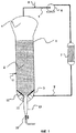
На фиг. 1 показан реактор с псевдоожиженным слоем для газофазной полимеризации олефинов, в каковом реакторе с псевдоожиженным слоем имеется газораспределительная решетка настоящего изобретения.In FIG. 1 shows a fluidized bed reactor for the gas phase polymerization of olefins, in which a fluidized bed reactor has a gas distribution grid of the present invention.
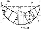
На фиг. 2а и 2b показана нижняя часть реактора с псевдоожиженным слоем, представленного на фиг. 1: фиг. 2а представляет собой вертикальную боковую проекцию распределительной решетки, а фиг. 2b - горизонтальную проекцию распределительной решетки.In FIG. 2a and 2b show the lower part of the fluidized bed reactor of FIG. 1: FIG. 2a is a vertical side view of the distribution grid, and FIG. 2b is a horizontal projection of a distribution grid.
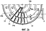
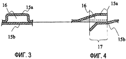
На фиг. 3 показано радиальное сечение одного паза, образованного при перекрывании двух соседних лотков распределительной решетки, представленной на фиг. 2а и 2b. На фиг. 4 показано тангенциальное сечение паза, представленного на фиг. 3.In FIG. 3 shows a radial section of one groove formed by overlapping two adjacent trays of the distribution grid of FIG. 2a and 2b. In FIG. 4 shows a tangential section of the groove of FIG. 3.
На фиг. 1 показан реактор с псевдоожиженным слоем, включающий псевдоожиженный слой 2 полимера, газораспределительную решетку 3 настоящего изобретения и зону снижения скорости или зону разъединения 4, расположенную над слоем полимера 2.In FIG. 1 shows a fluidized bed reactor including a polymer fluidized bed 2, a
Зона снижения скорости 4, как правило, имеет больший диаметр, чем диаметр той части реактора, где находится псевдоожиженный слой. Газообразный поток, выходящий из зоны снижения скорости 4 сверху, может содержать помимо непрореагировавших мономеров также инертные конденсирующиеся газы, такие как пропан, а также инертные неконденсирующиеся газы, такие как азот. Указанный газообразный поток подвергают сжатию, охлаждению и рециркулируют в нижнюю часть реактора с псевдоожиженным слоем: из верхней части зоны снижения скорости 4 газообразный поток подают по рециркуляционному трубопроводу 5 в компрессор 6 и затем в теплообменник 7. Если нужно, рециркуляционный трубопровод 5 может быть соединен с трубопроводом 8 для подачи мономеров, регуляторов молекулярного веса и, необязательно, инертных газов. При прохождении через теплообменник 8 газообразный поток охлаждается, после чего по трубопроводу 9 его направляют в нижнюю часть реактора с псевдоожиженным слоем. Циркулирующий газ, если нужно, может быть охлажден до температуры, которая ниже температуры точки росы одного или более из компонентов газа, чтобы обеспечить работу реактора со сконденсированным материалом, то есть в конденсатном режиме.
Как правило, в реактор с псевдоожиженным слоем 1 подают различные компоненты катализатора полимеризации по трубопроводу 10, который, предпочтительно, расположен в нижней части псевдоожиженного слоя 2. Вход трубопровода 9 в реактор расположен непосредственно под распределительной решеткой 3, а направление входного отверстия указанного трубопровода 9 таково, что способствует созданию в зоне под распределительной решеткой 3 центробежного движения.Typically, various components of the polymerization catalyst are fed into the fluidized bed reactor 1 through a
В соответствии с альтернативным вариантом осуществления изобретения, вследствие особой конструкции газораспределителя 3, зона разъединения 4 может отсутствовать, благодаря чему снижается риск закупоривания отверстий тонкодисперсными частицами, захваченными циркулирующим газом.According to an alternative embodiment of the invention, due to the special design of the
Распределительная решетка 3 настоящего изобретения поддерживается множеством брусов 11, выступающих из стенок дна реактора в зоне, лежащей ниже распределительной решетки. Соответственно центру газораспределителя 3 располагается круглое отверстие 12, через которое гранулы полимера могут выводиться из псевдоожиженного слоя непрерывно или дискретно, непрерывный режим является предпочтительным. Отверстие 12 газораспределителя 3 переходит в трубу 13 для выгрузки частиц полимера из реактора. Выгруженные частицы затем подают в соответствующие устройства (не показаны) для дегазации и экструдирования.The
На фиг. 2а и 2b газораспределитель 3, соответствующий настоящему изобретению, показан более детально. Как видно на фиг. 2а, газораспределитель имеет форму стенок усеченного конуса, то есть в поперечном сечении - форму трапеции. Угол при вершине усеченного конуса в этом варианте осуществления составляет 120°.In FIG. 2a and 2b, the
Газораспределитель включает три кольцевых модуля 14а, 14b, 14с лотков 15, соединенных друг с другом с образованием боковых стенок указанного усеченного конуса. Кольцевые модули 14а, 14b, 14с состоят из лотков 15, имеющих форму пластин, смонтированных на кольцевых опарах так, что каждый лоток соединен с двумя соседними лотками. Кольцевые модули поддерживаются при помощи брусов 11, выступающих из стенок дна реактора в зоне, лежащей ниже распределительной решетки.The gas distributor includes three
Если лотки соединены друг с другом разъемным образом, газораспределитель настоящего изобретения очень легко собирать и разбирать или заменять некоторые лотки во время технического обслуживания.If the trays are connected to each other in a detachable manner, the gas distributor of the present invention is very easy to assemble and disassemble or replace some of the trays during maintenance.
В конкретном варианте осуществления, показанном на фиг. 2, периферический кольцевой модуль 14а включает 44 лотка, средний кольцевой модуль 14b включает 30 лотков, а внутренний кольцевой модуль 14с включает 18 лотков.In the specific embodiment shown in FIG. 2, the
Число пазов 16 увеличивается от внутреннего к периферическому кольцевому модулю так, что число пазов на единицу площади на всей решетке остается, по существу, постоянным. Модульная конструкция, однако, может быть легко адаптирована к различным нуждам путем увеличения или уменьшения числа лотков в каждом кольцевом модуле. В конкретном варианте осуществления, показанном на фиг. 2, каждый лоток 15 включает семь пазов 16 с одинаковым поперечным сечением.The number of
Пазам 16 придают такую форму, что образующееся отверстие для выхода газа расположено в плоскости двух соседних лотков 15 тангенциально. В этом случае пазы 16 могут создавать вихревое, циклоническое движение потока газа над газораспределительной решеткой 3, установленной внизу реактора с псевдоожиженным слоем, показанного на фиг. 1.The
Как было указано, ожижающий газ поступает в реактор по трубопроводу 9 непосредственно под распределительной решеткой 3, а направление входного отверстия этого трубопровода таково, что в зоне под распределительной решеткой 3 создается центробежное движение. Кроме того, поток газа, поступающего по трубопроводу 9, проходит по аналогично ориентированным пазам 16 распределительной решетки 3, что благоприятствует эффекту каналирования газа в пазах 16.As indicated, the fluidizing gas enters the reactor through a
На фиг. 3 показано радиальное сечение одного паза 16, то есть сечение, перпендикулярное направлению движения газа через паз 16.In FIG. 3 shows a radial section of one
Паз 16 образован путем перекрывания двух соседних лотков 15а и 15b. Каждый лоток создает с одной стороны нижнюю часть пазов и с другой стороны - верхнюю часть пазов. Такое расположение, по существу, одинаково для всех лотков газораспределителя. Более подробно, верхний край паза 16 образован первым лотком 15а, нижний край паза 16 образован вторым лотком 15b, прикрепленным к первому лотку 15а. Первый лоток 15а изогнут так, что образует пазы 16 с, по существу, прямоугольным сечением. Первый лоток 15а очерчивает верхний и боковые края прямоугольного паза 16, а второй лоток 15b очерчивает нижний край прямоугольного паза 16. Ширина пазов 16 в данном варианте осуществления изобретения более чем в два раза превышает его высоту.The
На фиг. 4 показано тангенциальное сечение паза 16, то есть сечение, ориентированное вдоль направления потока газа, проходящего через паз 16. Здесь также видно, что верхняя часть паза 16 образована одним лотком, а нижняя часть образована следующим лотком. Пазы 16 в направлении потока состоят, по существу, из трех частей: входной части, центральной части и выходной части. В центральной части лотки 15а и 15b, по существу, параллельны, длина указанной центральной части больше ее высоты, а ее наклон относительно плоскости лотков, по существу, равен нулю. Высота входной части по движению потока немного сужена, тогда как выходная часть слегка поднимается и образована только нижним лотком 15b. Оси указанных пазов 16 расположены тангенциально по отношению к плоскости указанных лотков 15а, 15b.In FIG. 4 shows the tangential section of the
Входная часть каждого паза 16 поддерживается чистой благодаря входящему потоку ожижающего газа, подаваемого по трубопроводу циркулирующего газа в реактор. Пазы 16, предпочтительно, располагают на противоположных сторонах одного и того же лотка 15 не в линию, а в шахматном порядке: в этом случае газ, непрерывно поступающий из предыдущей группы пазов, может поддерживать зоны между пазами последующей группы чистыми.The inlet of each
Пазы могут иметь любую форму, например треугольную, прямоугольную, полукруглую или круглую, то есть не ограничиваются конкретной формой. Является предпочтительным формировать пазы, по существу, прямоугольной формы.The grooves can be of any shape, for example triangular, rectangular, semicircular or round, that is, they are not limited to a specific shape. It is preferred to form grooves of a substantially rectangular shape.
Поперечное сечение и размер пазов, предпочтительно, одинаковые. Однако также возможно, чтобы на внутренней части и внешней части решетки, вблизи стенки реактора, поперечное сечение и размер пазов различались. Длина пазов может регулироваться путем увеличения или уменьшения зоны перекрывания соседних лотков. Таким образом, обеспечивается значительная гибкость конструкции без необходимости регулирования собственной толщины газораспределителя или без необходимости наличия колпачков над пазами решетки. Путем выбора лотков с пазами различной формы или поперечного сечения можно легко адаптировать газораспределитель к различным условиям процесса. Распределительная решетка настоящего изобретения может быть с успехом использована во многих устройствах, в которых осуществляется псевдоожижение порошкообразного полимера, не обязательно имея в виду реакцию полимеризации мономеров. Например, распределительная решетка также может быть установлена внизу сушилки, предназначенной для сушки частиц полимера в псевдоожиженном состоянии восходящим непрерывным потоком горячего сушильного газа, такого как азот.The cross section and groove size are preferably the same. However, it is also possible that on the inner part and the outer part of the grating, near the wall of the reactor, the cross section and the size of the grooves are different. The length of the grooves can be adjusted by increasing or decreasing the overlapping zone of adjacent trays. Thus, significant design flexibility is provided without the need to control the intrinsic thickness of the gas distributor or without the need for caps over the grooves of the grill. By selecting trays with grooves of various shapes or cross-sections, the gas distributor can easily be adapted to various process conditions. The distribution grid of the present invention can be successfully used in many devices in which the fluidized polymer is fluidized, not necessarily having in mind the polymerization reaction of the monomers. For example, a distribution grid can also be installed at the bottom of a dryer for drying polymer particles in a fluidized state by an upward continuous flow of hot drying gas, such as nitrogen.
В частности, использование газораспределителя настоящего изобретения позволяет получить следующие преимущества:In particular, the use of the gas distributor of the present invention provides the following advantages:
1) при тангенциальном выходе ожижающего газа из пазов в слое полимера вблизи решетки для создания псевдоожиженного слоя создается вихревое движение и вследствие этого сводится к минимуму образование горячих зон в нижней части псевдоожиженного слоя. Указанное вихревое, циклоническое движение потока газа также способствует повышению гомогенности распределения газа внутри слоя псевдоожиженного полимера;1) in the case of a tangential exit of the fluidizing gas from the grooves in the polymer layer near the grating, a vortex movement is created to create a fluidized bed and, as a result, the formation of hot zones in the lower part of the fluidized bed is minimized. The specified vortex, cyclonic movement of the gas stream also contributes to an increase in the homogeneity of the gas distribution inside the fluidized polymer layer;
2) наклон пазов относительно вертикальной оси резервуара или реактора предотвращает проникновение частиц полимера глубоко в пазы, поэтому риск закупоривания распределительной решетки пренебрежимо мал;2) the slope of the grooves relative to the vertical axis of the tank or reactor prevents the penetration of polymer particles deep into the grooves, so the risk of clogging the distribution grid is negligible;
3) в отличие от конструкций известного уровня техники периферическая часть распределительной решетки непрерывно подвергается воздействию напора тангенциального потока газа, выходящего из пазов, вследствие этого в указанной периферической части может быть значительно снижено отложение твердой фазы (минимизация горячих зон).3) in contrast to the constructions of the prior art, the peripheral part of the distribution grid is continuously exposed to the pressure of the tangential flow of gas exiting the grooves, as a result of this, the deposition of the solid phase can be significantly reduced in the indicated peripheral part (minimization of hot zones).
Когда распределительная решетка установлена внизу реактора с псевдоожиженным слоем для полимеризации олефинов, она пригодна для обеспечения оптимального распределения газообразных мономеров в псевдоожиженном слое полимера, поэтому гарантируется непрерывное и бесперебойное осуществление процесса полимеризации, на которое не оказывают влияния недостатки, свойственные газораспределителям известного уровня техники.When the distribution lattice is installed at the bottom of the fluidized bed reactor for the polymerization of olefins, it is suitable for ensuring the optimal distribution of gaseous monomers in the fluidized bed of the polymer, therefore, the continuous and uninterrupted operation of the polymerization process is guaranteed, which is not affected by the disadvantages inherent in prior art gas distributors.
Следовательно, второй целью настоящего изобретения является реактор с псевдоожиженным слоем для газофазной полимеризации α-олефинов, причем реактор с псевдоожиженным слоем оборудован газораспределительной решеткой, расположенной у его основания, системой циркуляции газа для обеспечения охлаждения и циркуляции непрореагировавшего газа из верхней части указанного реактора к указанной распределительной решетке и трубой для непрерывного выведения полимера из реактора, отличающийся тем, что указанная распределительная решетка включает множество лотков, расположенных с образованием боковых стенок перевернутого конуса, причем множество лотков соединено друг с другом с образованием пазов в зонах перекрытия соседних лотков.Therefore, the second objective of the present invention is a fluidized bed reactor for the gas phase polymerization of α-olefins, the fluidized bed reactor equipped with a gas distribution grid located at its base, a gas circulation system to provide cooling and circulation of unreacted gas from the upper part of the specified reactor to the specified distribution a lattice and a pipe for continuous removal of polymer from the reactor, characterized in that the said distribution grid including there are many trays located with the formation of the side walls of the inverted cone, and many trays are connected to each other with the formation of grooves in the overlapping zones of adjacent trays.
В устройстве, показанном на фиг. 1, газораспределительная решетка 3 имеет коническую форму и окружает входное отверстие 12 отводящей трубы 13, предназначенной для выведения частиц полимера из реактора 1. Входное отверстие 12 отводящей трубы 13 расположено, предпочтительно, в центре распределительной решетки 3.In the device shown in FIG. 1, the
Отводящая труба 13 снабжена регулирующим устройством 18, таким как выпускной клапан, пригодным для регулирования массового расхода полимера, отводимого из реактора 1. Отверстие выпускного клапана 18 непрерывно изменяют так, чтобы высота псевдоожиженного слоя полимера в реакторе была постоянной.The
Отводящая труба 13 может иметь постоянный диаметр, однако, предпочтительно, включает несколько секций с уменьшающимися книзу диаметрами. Регулировочный клапан 18 располагают, предпочтительно, соответственно сужению между секцией с большим диаметром и секцией с меньшим диаметром, как показано на фиг. 1.The
Реактор с псевдоожиженным слоем, показанный на фиг. 1, снабжен газораспределительной решеткой настоящего изобретения, особенно пригодной для промышленного использования в непрерывном процессе газофазной полимеризации одного или более олефинового мономера формулы СН2=CHR, где R означает водород или углеводородный радикал, включающий 1-12 атомов углерода. По выбору, газофазная полимеризация может быть осуществлена в присутствии одного или более алкана С2-С8 или циклоалкана в качестве конденсирующихся газов.The fluidized bed reactor shown in FIG. 1 is provided with a gas distribution grid of the present invention, particularly suitable for industrial use in a continuous gas phase polymerization process of one or more olefin monomers of the formula CH 2 = CHR, where R is hydrogen or a hydrocarbon radical of 1-12 carbon atoms. Optionally, gas phase polymerization can be carried out in the presence of one or more C 2 -C 8 alkane or cycloalkane as condensing gases.
Следовательно, еще одной целью настоящего изобретения является способ газофазной полимеризации одного или более α-олефина в реакторе с псевдоожиженным слоем в присутствии катализатора полимеризации, причем реактор с псевдоожиженным слоем оборудован решеткой для создания псевдоожиженного слоя, расположенной у его основания, системой циркуляции газа для обеспечения охлаждения и циркуляции непрореагировавшего газа из верхней части указанного реактора к указанной распределительной решетке, причем способ отличается тем, что указанный непрореагировавший газ непрерывно движется через пазы распределительной решетки, включающей множество лотков, расположенных с образованием боковых стенок перевернутого конуса, причем множество лотков соединено друг с другом с образованием указанных пазов в зонах перекрытия соседних лотков.Therefore, another objective of the present invention is a method for gas-phase polymerization of one or more α-olefins in a fluidized bed reactor in the presence of a polymerization catalyst, wherein the fluidized bed reactor is equipped with a grid to create a fluidized bed located at its base, a gas circulation system to provide cooling and circulating unreacted gas from the upper part of said reactor to said distribution grid, the method being characterized in that said unreacted gas continuously moves through the grooves of the distribution grid, including many trays located with the formation of the side walls of the inverted cone, and many trays are connected to each other with the formation of these grooves in the areas of overlapping adjacent trays.
Производимый полиолефин непрерывно выводят из реактора с псевдоожиженным слоем 1 посредством отводящей трубы 13, выходящей из вершины указанного перевернутого конуса, образованного указанной конфигурацией указанного множества лотков.The produced polyolefin is continuously withdrawn from the fluidized bed reactor 1 by means of a
По отводящей трубе 13 выводимый полиолефин поступает в резервуар для разделения (не показан), где полученный полимер отделяют от непрореагировавших мономеров и инертных газообразных соединений, каковые отделенные газообразные компоненты непрерывно рециркулируют в реактор с псевдоожиженным слоем 1.Through the
Условия полимеризации соответствуют обычно применяемым в газофазных реакторах для полимеризации олефинов, то есть температура составляет от 60 до 120°С, давление составляет от 5 до 40 бар (0,5-4 МПа).The polymerization conditions correspond to those commonly used in gas phase reactors for the polymerization of olefins, that is, the temperature is from 60 to 120 ° C, the pressure is from 5 to 40 bar (0.5-4 MPa).
Способ газофазной полимеризации настоящего изобретения может быть объединен с обычными технологиями, осуществляемыми в суспензии, в массе или в газовой фазе, с целью проведения многостадийного процесса полимеризации. Следовательно, выше или ниже по ходу технологического потока от устройства полимеризации настоящего изобретения может быть предусмотрена одна или более стадия полимеризации, осуществляемая в петлевом реакторе или в обычном реакторе с псевдоожиженным слоем или в реакторе с перемешиваемым слоем. В частности, реакторы газофазной полимеризации с объединенными зонами полимеризации, как описано в ЕР 782587 и ЕР 1012195, могут эффективно функционировать выше или ниже по ходу технологического потока от устройства настоящего изобретения.The gas phase polymerization method of the present invention can be combined with conventional technologies carried out in suspension, in bulk or in the gas phase, with the aim of conducting a multi-stage polymerization process. Therefore, one or more polymerisation steps can be provided upstream or downstream of the polymerization apparatus of the present invention in a loop reactor or in a conventional fluidized bed reactor or in a stirred bed reactor. In particular, gas phase polymerization reactors with integrated polymerization zones, as described in EP 782587 and EP 1012195, can efficiently operate upstream or downstream from the device of the present invention.
Способ газофазной полимеризации позволяет производить большое количество порошкообразных олефинов с оптимальным распределением частиц по размерам и низким содержанием тонкодисперсных частиц. α-олефины, подвергаемые полимеризации по способу настоящего изобретения, предпочтительно, имеют формулу СН2=CHR, где R означает водород или углеводородный радикал, включающий 1-12 атомов углерода. К примерам полимеров, которые могут быть получены, относятся:The gas-phase polymerization method allows the production of a large number of powdered olefins with an optimal particle size distribution and a low content of fine particles. The α-olefins polymerized by the method of the present invention preferably have the formula CH 2 = CHR, where R is hydrogen or a hydrocarbon radical of 1-12 carbon atoms. Examples of polymers that can be prepared include:
- полиэтилены высокой плотности (HDPE с относительной плотностью более 0,940), включая гомополимеры этилена и сополимеры этилена и α-олефинов, содержащих от 3 до 12 атомов углерода;- high density polyethylene (HDPE with a relative density of more than 0.940), including homopolymers of ethylene and copolymers of ethylene and α-olefins containing from 3 to 12 carbon atoms;
- линейные полиэтилены низкой плотности (LLDPE с относительной плотностью менее 0,940) и очень низкой плотности и ультра низкой плотности (VLDPE и ULDPE с относительной плотностью менее 0,920 и до 0,880), состоящие из сополимеров этилена с одним или более α-олефином, содержащим от 3 до 12 атомов углерода;- linear low density polyethylenes (LLDPE with a relative density of less than 0.940) and very low density and ultra low density (VLDPE and ULDPE with a relative density of less than 0.920 and up to 0.880), consisting of copolymers of ethylene with one or more α-olefins containing from 3 up to 12 carbon atoms;
- эластомерные терполимеры этилена и пропилена с меньшей долей диенов или эластомерные сополимеры этилена и пропилена, в которых звенья, производные от этилена, присутствуют в количестве от 30 до 70 вес.%;- elastomeric terpolymers of ethylene and propylene with a smaller proportion of dienes or elastomeric copolymers of ethylene and propylene, in which units derived from ethylene are present in an amount of from 30 to 70 wt.%;
- изостатический полипропилен и кристаллические сополимеры пропилена и этилена и/или других α-олефинов с содержанием звеньев, производных от пропилена, более 85 вес.%;- isostatic polypropylene and crystalline copolymers of propylene and ethylene and / or other α-olefins with a content of units derived from propylene, more than 85 wt.%;
- изостатические сополимеры пропилена и α-олефинов, таких как 1-бутен, с содержанием α-олефина до 30 вес.%;- isostatic copolymers of propylene and α-olefins, such as 1-butene, with an α-olefin content of up to 30 wt.%;
- ударопрочные полимеры пропилена, получаемые путем последовательной полимеризации пропилена и смесей пропилена с этиленом, содержащих до 30 вес.% этилена;- high impact propylene polymers obtained by sequential polymerization of propylene and mixtures of propylene with ethylene containing up to 30 wt.% ethylene;
- атактический полипропилен и аморфные сополимеры пропилена и этилена и/или других α-олефинов, содержащие более 70 вес.% звеньев, производных от пропилена.- atactic polypropylene and amorphous copolymers of propylene and ethylene and / or other α-olefins, containing more than 70 wt.% units derived from propylene.
Описываемый в настоящем документе способ газофазной полимеризации не ограничивается использованием какого-либо определенного семейства катализаторов полимеризации. Настоящее изобретение применимо в случае любой экзотермической реакции полимеризации с любым катализатором, нанесенным на подложку или нет, независимо от того, проводится ли предварительная полимеризация.The gas phase polymerization process described herein is not limited to the use of any particular family of polymerization catalysts. The present invention is applicable in the case of any exothermic polymerization reaction with any catalyst supported on the substrate or not, regardless of whether pre-polymerization is carried out.
Реакция полимеризации может быть осуществлена в присутствии высокоактивных каталитических систем, таких как катализаторы Циглера-Натта, катализаторы с единым центром полимеризации, катализаторы на основе хрома, катализаторы на основе ванадия.The polymerization reaction can be carried out in the presence of highly active catalyst systems, such as Ziegler-Natta catalysts, catalysts with a single polymerization center, chromium-based catalysts, vanadium-based catalysts.
Каталитическая система Циглера-Натта включает катализаторы, полученные по реакции соединения переходного металла 4-10 групп Периодической таблицы элементов (новая система записи) с металлорганическим соединением элементов 1, 2 или 13 групп Периодической таблицы элементов.The Ziegler-Natta catalyst system includes catalysts obtained by the reaction of a transition metal compound of groups 4-10 of the Periodic Table of Elements (new recording system) with an organometallic compound of
В частности, соединение переходного металла может быть подобрано из соединений Ti, V, Zr, Cr и Hf. Предпочтительные соединения имеют формулу Ti(OR)nXy-n, в которой величина n заключена между 0 и y; y означает валентность титана; Х означает галоген, R означает углеводородную группу, состоящую из 1-10 атомов углерода, или группу COR. Из них особенно предпочтительны соединения титана, в которых имеется, по меньшей мере, одна связь Ti-галоген, такие как тетрагалиды титана или галогеналкоголяты. Конкретные предпочтительные соединения титана это TiCl3, TiCl4, Ti(OBu)4, Ti(OBu)Cl3, Ti(OBu)2Cl2, Ti(OBu)3Cl.In particular, the transition metal compound can be selected from compounds of Ti, V, Zr, Cr and Hf. Preferred compounds have the formula Ti (OR) n X yn in which n is between 0 and y; y is the valence of titanium; X is halogen, R is a hydrocarbon group of 1-10 carbon atoms, or a COR group. Of these, titanium compounds in which there is at least one Ti-halogen bond, such as titanium tetrahalides or halogenated alcohols, are particularly preferred. Particular preferred titanium compounds are TiCl 3 , TiCl 4 , Ti (OBu) 4 , Ti (OBu) Cl 3 , Ti (OBu) 2 Cl 2 , Ti (OBu) 3 Cl.
Предпочтительными металлорганическими соединениями являются Al-органические соединения, в частности соединения алкил-Al. Соединения алкил-Al, предпочтительно, подбирают из соединений триалкилалюминия, таких как, например, триэтилалюминий, триизобутилалюминий, три-н-бутилалюминий, три-н-гексилалюминий, три-н-октилалюминий. Также возможно использование галидов алкилалюминия, гидридов алкилалюминия или сесквихлоридов алкилалюминия, таких как AlEt2Cl и Al2Et3Cl3, по выбору, в смеси с указанными соединениями триалкилалюминия.Preferred organometallic compounds are Al-organic compounds, in particular alkyl-Al compounds. The alkyl-Al compounds are preferably selected from trialkylaluminum compounds, such as, for example, triethylaluminum, triisobutylaluminum, tri-n-butylaluminum, tri-n-hexylaluminum, tri-n-octylaluminum. It is also possible to use alkyl aluminum halides, alkyl aluminum hydrides or alkyl aluminum sesquichlorides, such as AlEt 2 Cl and Al 2 Et 3 Cl 3 , optionally in admixture with said trialkyl aluminum compounds.
Особенно подходящими катализаторами Циглера-Натта с высоким выходом являются те, в которых соединение титана нанесено на подложку из галида магния в активной форме, предпочтительно MgCl2 в активной форме. В частности, при производстве кристаллических полимеров олефинов CH2CHR, где R означает углеводородную группу С1-С10, внутренние электронодонорные соединения могут быть нанесены на подложку из MgCl2. Обычно их подбирают из сложных эфиров, простых эфиров, аминов и кетонов. В частности, является предпочтительным использовать соединения, принадлежащие к 1,3-диэфирам, циклическим простым эфирам, фталатам, бензоатам, ацетатам и сукцинатам.Particularly suitable Ziegler-Natta catalysts in high yield are those in which the titanium compound is supported on a magnesium halide substrate in an active form, preferably MgCl 2 in an active form. In particular, in the production of crystalline polymers of olefins CH 2 CHR, where R is a C 1 -C 10 hydrocarbon group, internal electron-donor compounds can be supported on a MgCl 2 support. Usually they are selected from esters, ethers, amines and ketones. In particular, it is preferable to use compounds belonging to 1,3-diesters, cyclic ethers, phthalates, benzoates, acetates and succinates.
Когда нужно получить высокоизотактический кристаллический полипропилен, желательно помимо электронодонора, присутствующего в твердом катализаторе, использовать внешний электронодонор, добавляемый к алкилалюминиевому компоненту сокатализатора или в реактор полимеризации. Такие внешние электронодоноры могут быть подобраны из спиртов, гликолей, сложных эфиров, кетонов, аминов, амидов, нитрилов, алкоксисиланов и простых эфиров. Электронодонорные соединения могут быть использованы индивидуально или в смеси друг с другом. Предпочтительное электронодонорное соединение подбирают из алифатических простых эфиров, сложных эфиров и алкоксисиланов. Предпочтительными простыми эфирами являются алифатические эфиры С2-С20, в частности циклические эфиры, предпочтительно, включающие 3-5 атомов углерода, такие как тетрагидрофуран, диоксан.When it is necessary to obtain highly isotactic crystalline polypropylene, it is desirable, in addition to the electron donor present in the solid catalyst, to use an external electron donor added to the alkyl aluminum component of the cocatalyst or to the polymerization reactor. Such external electron donors can be selected from alcohols, glycols, esters, ketones, amines, amides, nitriles, alkoxysilanes and ethers. Electron-donor compounds can be used individually or in a mixture with each other. A preferred electron donor compound is selected from aliphatic ethers, esters and alkoxysilanes. Preferred ethers are C 2 -C 20 aliphatic esters, in particular cyclic ethers, preferably comprising 3-5 carbon atoms, such as tetrahydrofuran, dioxane.
К другим пригодным катализаторам относятся катализаторы на основе ванадия, содержащие продукт реакции соединения ванадия с соединением алюминия, по выбору, в присутствии галогенированного органического соединения. Соединение ванадия, по выбору, может быть нанесено на неорганический носитель, такой как оксид кремния, оксид алюминия, хлорид магния. К пригодным соединениям ванадия относятся VCl4, VCl3, VOCl4, ацетилацетонат ванадия.Other suitable catalysts include vanadium based catalysts containing the reaction product of a vanadium compound with an aluminum compound, optionally in the presence of a halogenated organic compound. The vanadium compound optionally can be supported on an inorganic carrier such as silica, alumina, magnesium chloride. Suitable vanadium compounds include VCl 4 , VCl 3 , VOCl 4 , vanadium acetylacetonate.
К другим пригодным катализаторам относятся катализаторы на основе хрома, такие как оксид хрома на оксиде кремния, также известный как катализатор Филлипса.Other suitable catalysts include chromium-based catalysts, such as chromium oxide on silica, also known as a Phillips catalyst.
Другими пригодными катализаторами являются катализаторы с единым центром полимеризации, например катализаторные системы на основе металлоценов, включающие, по меньшей мере, соединение переходного металла, содержащее, по меньшей мере, одну B связь, и, по меньшей мере, алюмоксан или соединение, способное образовывать алкилметаллоценовый катион.Other suitable catalysts are catalysts with a single polymerization center, for example, metallocene-based catalyst systems comprising at least a transition metal compound containing at least one B bond and at least an alumoxane or a compound capable of forming an alkyl metallocene cation.
Катализатор может быть надлежащим образом использован в форме предварительно полимеризованного порошка, приготовленного заранее на стадии предварительной полимеризации при помощи катализатора, как описано выше. Предварительная полимеризация может быть осуществлена любым подходящим способом, например, как полимеризация в жидком углеводородном разбавителе или в газовой фазе в периодическом режиме, в полупериодическом режиме или в непрерывном режиме.The catalyst may be suitably used in the form of a prepolymerized powder prepared in advance in the prepolymerization step using a catalyst, as described above. The preliminary polymerization can be carried out by any suitable method, for example, as polymerization in a liquid hydrocarbon diluent or in the gas phase in a batch mode, in a batch mode or in a continuous mode.
Claims (13)
Applications Claiming Priority (2)
| Application Number | Priority Date | Filing Date | Title |
|---|---|---|---|
| EP06126686.2 | 2006-12-20 | ||
| EP06126686 | 2006-12-20 |
Publications (2)
| Publication Number | Publication Date |
|---|---|
| RU2009127726A RU2009127726A (en) | 2011-01-27 |
| RU2464083C2 true RU2464083C2 (en) | 2012-10-20 |
Family
ID=39047879
Family Applications (1)
| Application Number | Title | Priority Date | Filing Date |
|---|---|---|---|
| RU2009127726/02A RU2464083C2 (en) | 2006-12-20 | 2007-12-04 | Gas distribution grate for polymeriser |
Country Status (11)
| Country | Link |
|---|---|
| EP (1) | EP2125190B1 (en) |
| JP (1) | JP2010513622A (en) |
| KR (1) | KR101468471B1 (en) |
| CN (1) | CN101578134B (en) |
| AR (1) | AR064443A1 (en) |
| BR (1) | BRPI0720690B1 (en) |
| CL (1) | CL2007003670A1 (en) |
| RU (1) | RU2464083C2 (en) |
| SG (1) | SG177890A1 (en) |
| TW (1) | TWI426958B (en) |
| WO (1) | WO2008074632A1 (en) |
Families Citing this family (12)
| Publication number | Priority date | Publication date | Assignee | Title |
|---|---|---|---|---|
| DE102008012731A1 (en) | 2008-03-05 | 2009-09-24 | Uhde Gmbh | Device for discharging fine-grained or dust-like solids from a container |
| JP5420864B2 (en) * | 2008-08-01 | 2014-02-19 | 住友化学株式会社 | Vapor phase polymerization apparatus and olefin polymerization method |
| WO2011136492A2 (en) * | 2010-04-30 | 2011-11-03 | 대림산업 주식회사 | Gas-phase polymerization of alpha-olefins |
| EP2602269A1 (en) | 2011-12-06 | 2013-06-12 | Basell Polyolefine GmbH | Multistage process for the polymerization of olefins |
| US20150064089A1 (en) * | 2013-08-29 | 2015-03-05 | Honeywell International Inc. | Fluidized bed reactors including conical gas distributors and related methods of fluorination |
| US9511339B2 (en) * | 2013-08-30 | 2016-12-06 | Honeywell International Inc. | Series coupled fluidized bed reactor units including cyclonic plenum assemblies and related methods of hydrofluorination |
| CN110603092A (en) * | 2017-05-17 | 2019-12-20 | 巴塞尔聚烯烃股份有限公司 | Fluidized bed reactor with multiple recycle gas inlet nozzles |
| ES2806646T3 (en) * | 2017-11-17 | 2021-02-18 | Borealis Ag | Procedure to improve the cooling capacity of a gas-solid olefin polymerization reactor |
| ES2795985T3 (en) * | 2017-11-17 | 2020-11-25 | Borealis Ag | Return fluidizing gas splitting procedure in a solid gas olefin polymerization reactor |
| WO2022258632A1 (en) | 2021-06-08 | 2022-12-15 | Basell Polyolefine Gmbh | Gas-phase polymerization apparatus |
| WO2024056538A1 (en) | 2022-09-12 | 2024-03-21 | Basell Poliolefine Italia S.R.L. | Fluidized-bed reactor for the gas-phase polymerization of olefins |
| WO2024056539A1 (en) | 2022-09-12 | 2024-03-21 | Basell Poliolefine Italia S.R.L. | Fluidized-bed reactor for the gas-phase polymerization of olefins |
Citations (4)
| Publication number | Priority date | Publication date | Assignee | Title |
|---|---|---|---|---|
| US4518750A (en) * | 1982-03-10 | 1985-05-21 | Montedison S.P.A. | Fluid bed reactor |
| DE3705343A1 (en) * | 1986-02-20 | 1987-09-24 | Magyar Tudomanyos Akademia | DEVICE AND METHOD FOR FLUIDIZING CONTACT OF SUBSTANCES |
| US5101742A (en) * | 1990-06-22 | 1992-04-07 | Energy Products Of Idaho | Fluidized bed combustion |
| RU2126015C1 (en) * | 1992-06-18 | 1999-02-10 | Монтелл Текнолоджи Компани Б.В. | Method of gas-phase polymerization of olefins and apparatus for its embodiment (versions) |
Family Cites Families (7)
| Publication number | Priority date | Publication date | Assignee | Title |
|---|---|---|---|---|
| DE1186832B (en) * | 1958-08-05 | 1965-02-11 | Exxon Research Engineering Co | Device for the distribution of gas flows in a fluidized bed reactor |
| US3817696A (en) * | 1972-08-09 | 1974-06-18 | H Hereth | Method of and apparatus for fluidized bed treatment of solids or liquids |
| US4442796A (en) * | 1982-12-08 | 1984-04-17 | Electrodyne Research Corporation | Migrating fluidized bed combustion system for a steam generator |
| CA1241525A (en) * | 1984-08-24 | 1988-09-06 | Larry L. Simpson | Fluidized bed polymerization reactors |
| EP1099472A3 (en) * | 1999-11-12 | 2002-04-10 | Union Carbide Chemicals & Plastics Technology Corporation | Gas fluidized bed product removal apparatus |
| CN1259183C (en) * | 2001-05-22 | 2006-06-14 | 华东理工大学 | Stirring-spraying fluidized bed and its application in preparing fibre reinforced composite material |
| JP4616248B2 (en) * | 2003-04-17 | 2011-01-19 | バーゼル・ポリオレフィン・イタリア・ソチエタ・ア・レスポンサビリタ・リミタータ | Gas phase olefin polymerization method |
-
2007
- 2007-12-04 BR BRPI0720690-9A patent/BRPI0720690B1/en active IP Right Grant
- 2007-12-04 KR KR1020097012654A patent/KR101468471B1/en active IP Right Grant
- 2007-12-04 EP EP07847779.1A patent/EP2125190B1/en active Active
- 2007-12-04 CN CN200780047387.4A patent/CN101578134B/en active Active
- 2007-12-04 JP JP2009541957A patent/JP2010513622A/en not_active Ceased
- 2007-12-04 RU RU2009127726/02A patent/RU2464083C2/en active
- 2007-12-04 SG SG2011091618A patent/SG177890A1/en unknown
- 2007-12-04 WO PCT/EP2007/063277 patent/WO2008074632A1/en active Application Filing
- 2007-12-10 TW TW096147000A patent/TWI426958B/en active
- 2007-12-18 CL CL200703670A patent/CL2007003670A1/en unknown
- 2007-12-19 AR ARP070105720A patent/AR064443A1/en unknown
Patent Citations (4)
| Publication number | Priority date | Publication date | Assignee | Title |
|---|---|---|---|---|
| US4518750A (en) * | 1982-03-10 | 1985-05-21 | Montedison S.P.A. | Fluid bed reactor |
| DE3705343A1 (en) * | 1986-02-20 | 1987-09-24 | Magyar Tudomanyos Akademia | DEVICE AND METHOD FOR FLUIDIZING CONTACT OF SUBSTANCES |
| US5101742A (en) * | 1990-06-22 | 1992-04-07 | Energy Products Of Idaho | Fluidized bed combustion |
| RU2126015C1 (en) * | 1992-06-18 | 1999-02-10 | Монтелл Текнолоджи Компани Б.В. | Method of gas-phase polymerization of olefins and apparatus for its embodiment (versions) |
Also Published As
| Publication number | Publication date |
|---|---|
| KR101468471B1 (en) | 2014-12-04 |
| TW200836837A (en) | 2008-09-16 |
| BRPI0720690B1 (en) | 2018-04-03 |
| CL2007003670A1 (en) | 2008-07-25 |
| JP2010513622A (en) | 2010-04-30 |
| TWI426958B (en) | 2014-02-21 |
| CN101578134B (en) | 2015-05-20 |
| AR064443A1 (en) | 2009-04-01 |
| BRPI0720690A2 (en) | 2014-02-25 |
| SG177890A1 (en) | 2012-02-28 |
| KR20090101186A (en) | 2009-09-24 |
| EP2125190B1 (en) | 2019-01-16 |
| CN101578134A (en) | 2009-11-11 |
| WO2008074632A1 (en) | 2008-06-26 |
| RU2009127726A (en) | 2011-01-27 |
| EP2125190A1 (en) | 2009-12-02 |
Similar Documents
| Publication | Publication Date | Title |
|---|---|---|
| RU2464083C2 (en) | Gas distribution grate for polymeriser | |
| EP1962996B1 (en) | Gas-phase process and apparatus for the polymerization of olefins | |
| CN1933902B (en) | Method and apparatus for producing polymers | |
| US8128878B2 (en) | Gas-phase polymerization of alpha-olefin | |
| KR101855069B1 (en) | Process and apparatus for the gas-phase polymerization of olefins | |
| US20100311923A1 (en) | Spouted-fluidized bed-type olefin polymerization reactor | |
| WO2009080660A1 (en) | Process for the gas-phase polymerization of olefins | |
| JP4960858B2 (en) | Method for controlling the flow rate of a polymer in a polymerization process | |
| CN115487755B (en) | Fluidized bed reactor with multiple recycle gas inlet nozzles | |
| WO2007033941A1 (en) | Gas-phase process for the polymerization of olefins | |
| CN1238237A (en) | Gas-phase fluidized-bed reactor | |
| WO2009144144A1 (en) | Process for the gas-phase polymerization of olefins | |
| US20110152489A1 (en) | Apparatus and process for gas phase fluidised bed polymerisation reaction | |
| JP2010280867A (en) | Olefin polymerization reactor, polyolefin manufacturing system, and polyolefin manufacturing method | |
| KR20180048752A (en) | Method for continuous polymerization of olefin monomers in a reactor | |
| US7834108B2 (en) | Powder transfer device and polyolefin production process | |
| JP2023554278A (en) | Reactor for olefin gas phase polymerization |
Legal Events
| Date | Code | Title | Description |
|---|---|---|---|
| PD4A | Correction of name of patent owner | ||
| QB4A | Licence on use of patent |
Free format text: LICENCE FORMERLY AGREED ON 20181019 Effective date: 20181019 |