RU2463532C2 - Refrigerating device housing - Google Patents
Refrigerating device housing Download PDFInfo
- Publication number
- RU2463532C2 RU2463532C2 RU2009142883/13A RU2009142883A RU2463532C2 RU 2463532 C2 RU2463532 C2 RU 2463532C2 RU 2009142883/13 A RU2009142883/13 A RU 2009142883/13A RU 2009142883 A RU2009142883 A RU 2009142883A RU 2463532 C2 RU2463532 C2 RU 2463532C2
- Authority
- RU
- Russia
- Prior art keywords
- wall
- cover
- sleeve
- passage
- valve
- Prior art date
Links
Images


Classifications
-
- F—MECHANICAL ENGINEERING; LIGHTING; HEATING; WEAPONS; BLASTING
- F25—REFRIGERATION OR COOLING; COMBINED HEATING AND REFRIGERATION SYSTEMS; HEAT PUMP SYSTEMS; MANUFACTURE OR STORAGE OF ICE; LIQUEFACTION SOLIDIFICATION OF GASES
- F25D—REFRIGERATORS; COLD ROOMS; ICE-BOXES; COOLING OR FREEZING APPARATUS NOT OTHERWISE PROVIDED FOR
- F25D17/00—Arrangements for circulating cooling fluids; Arrangements for circulating gas, e.g. air, within refrigerated spaces
- F25D17/04—Arrangements for circulating cooling fluids; Arrangements for circulating gas, e.g. air, within refrigerated spaces for circulating air, e.g. by convection
- F25D17/042—Air treating means within refrigerated spaces
- F25D17/047—Pressure equalising devices
-
- F—MECHANICAL ENGINEERING; LIGHTING; HEATING; WEAPONS; BLASTING
- F25—REFRIGERATION OR COOLING; COMBINED HEATING AND REFRIGERATION SYSTEMS; HEAT PUMP SYSTEMS; MANUFACTURE OR STORAGE OF ICE; LIQUEFACTION SOLIDIFICATION OF GASES
- F25D—REFRIGERATORS; COLD ROOMS; ICE-BOXES; COOLING OR FREEZING APPARATUS NOT OTHERWISE PROVIDED FOR
- F25D23/00—General constructional features
- F25D23/02—Doors; Covers
Abstract
Description
Область техникиTechnical field
Предлагаемое изобретение относится к корпусу для холодильного аппарата с уравнительным клапаном.The present invention relates to a housing for a refrigerating apparatus with equalizing valve.
Уровень техникиState of the art
При каждом открытии дверки холодильного аппарата в его внутреннюю полость попадает теплый воздух, который охлаждается внутри после закрытия дверки и создает пониженное давление. Это пониженное давление приводит к тому, что дверку после закрытия будет трудно вновь открыть до тех пор, пока давление во внутренней полости и давление окружающей среды не выровняются. Чтобы дверка могла легко открываться в любое время, предлагалось установить в стенку корпуса такого аппарата уравнительный клапан, который в случае преобладания во внутренней полости пониженного давления пропускал бы воздух снаружи вовнутрь и закрывался бы, как только давление окружающей среды становилось бы равным давлению во внутренней полости. Закрытие клапана позволило бы исключить проникновение теплого и влажного внешнего воздуха во внутреннюю полость вне фаз выравнивания давления.Each time the door of the refrigerator is opened, warm air enters its internal cavity, which cools inside after closing the door and creates a reduced pressure. This reduced pressure makes it difficult to reopen the door after closing until the pressure in the internal cavity and the pressure of the environment are equal. To make the door easy to open at any time, it was proposed to install a balancing valve in the wall of the casing of such an apparatus, which, if the reduced pressure prevailed in the internal cavity, would let air pass from outside to inside and close as soon as the ambient pressure became equal to the pressure in the internal cavity. Closing the valve would prevent the penetration of warm and moist external air into the internal cavity outside the pressure equalization phases.
Предпринимавшиеся попытки показали, что такой уравнительный клапан должен иметь большой диаметр, чтобы можно было быстро и без шума выровнять давление. Такой уравнительный клапан представляет собой слабое место в изоляции холодильного аппарата, причем приток тепла во внутреннюю полость значительно увеличивается с увеличением диаметра уравнительного клапана.Attempts have shown that such a balancing valve must have a large diameter so that the pressure can be quickly and quietly equalized. Such a balancing valve is a weak point in the insulation of the refrigeration apparatus, and the heat influx into the internal cavity increases significantly with increasing diameter of the balancing valve.
Раскрытие изобретенияDisclosure of invention
Поэтому задачей предлагаемого изобретения является разработка корпуса для холодильного аппарата с уравнительным клапаном, который, с одной стороны, обеспечил бы бесшумное или, по меньшей мере, очень малошумное выравнивание давления, а с другой стороны, предотвратил бы сильный приток тепла через уравнительный клапан.Therefore, the objective of the invention is to develop a housing for a refrigeration apparatus with equalizing valve, which, on the one hand, would provide silent or at least very low pressure equalization, and on the other hand, would prevent a strong influx of heat through the equalization valve.
Задача решается за счет того, что в корпусе для холодильного аппарата, у которого в сквозном проходе стенки установлен уравнительный клапан, сквозной проход, по меньшей мере, с одной стороны стенки снабжен воздухопроницаемой крышкой. Такая крышка не мешает выравниванию давления, но препятствует медленным воздушным потокам, обусловленным, в частности, конвекцией. Поскольку таким потокам создается препятствие в месте установки уравнительного клапана, теплообмен с окружающей средой замедляется, и, пока через уравнительный клапан не поступает воздуха, воздух, находящийся между уравнительным клапаном и крышкой, служит дополнительным изоляционным слоем.The problem is solved due to the fact that in the housing for the refrigeration apparatus, in which an equalizing valve is installed in the through passage of the wall, the through passage, at least on one side of the wall, is provided with a breathable cover. Such a cover does not interfere with the equalization of pressure, but prevents slow air flows due, in particular, to convection. Since such flows are obstructed at the installation site of the equalizing valve, heat exchange with the environment slows down, and until air enters through the equalizing valve, the air between the equalizing valve and the cover serves as an additional insulating layer.
Согласно предпочтительному варианту исполнения изобретения крышка представляет собой решетку.According to a preferred embodiment of the invention, the lid is a grill.
В альтернативном варианте крышка может представлять собой закрывающую сквозной проход пластину, которая, разумеется, должна быть удалена от стенки с уравнительным клапаном на некоторое расстояние, чтобы не препятствовать притоку воздуха к уравнительному клапану или отводу воздуха от него в ходе процесса выравнивания давления.Alternatively, the cover may be a plate covering the through passage, which, of course, should be removed from the wall with the equalizing valve by a certain distance so as not to impede the flow of air to the equalizing valve or the air outlet from it during the pressure equalization process.
Крышка может быть снабжена фиксирующей частью, входящей в углубление.The cover may be provided with a fixing part included in the recess.
Предпочтительно крышка устанавливается на внутреннюю сторону стенки. Если крышка будет установлена на наружной стороне, может случиться так, что температура между крышкой и уравнительным клапаном упадет ниже точки росы, то есть станет возможным постоянное осаждение конденсата. В варианте размещения с внутренней стороны такой опасности не существует, так как в этом случае температура в области между уравнительным клапаном и крышкой будет выше, чем в связанной с ней внутренней полости. Также это снижает вероятность обледенения уравнительного клапана под действием воздуха, поступающего в корпус в ходе процесса выравнивания давления.Preferably, the lid is mounted on the inside of the wall. If the cover is installed on the outside, it may happen that the temperature between the cover and the equalizing valve drops below the dew point, that is, it becomes possible to continuously precipitate condensate. In the arrangement with the inside, there is no such danger, since in this case the temperature in the region between the equalizing valve and the cover will be higher than in the associated internal cavity. It also reduces the likelihood of equalization of the equalization valve due to air entering the housing during the pressure equalization process.
Если в стенке, в которой установлен уравнительный клапан, проходит вентиляционный канал, предназначенный, в частности, для воздухообмена между камерой для хранения продуктов и камерой испарителя, то крышка уравнительного клапана может быть выполнена очень незаметной за счет того, что она встраивается в окружающую отверстие канала рамку.If there is a ventilation channel in the wall in which the equalizing valve is installed, which is intended, in particular, for air exchange between the food storage chamber and the evaporator chamber, then the equalizing valve cover can be made very invisible due to the fact that it is built into the surrounding channel opening the frame.
Предпочтительно рамка содержит также перекрывающую отверстие вентиляционного канала решетку.Preferably, the frame also comprises a grill covering the opening of the ventilation duct.
Уравнительный клапан предпочтительно устанавливается на дверке корпуса, так как в этом варианте наиболее низка вероятность подсасывания вовнутрь воздуха, нагретого отходящим теплом холодильного аппарата, во время процесса выравнивания давления.The equalizing valve is preferably mounted on the door of the housing, since in this embodiment the probability of sucking inward the air heated by the waste heat of the refrigerator during the pressure equalization process is the lowest.
Уравнительный клапан может быть образован простым способом за счет установки в сквозной проход надломленного эластичного листа с кромками, прилегающими к внутренней стенке сквозного прохода.The balancing valve can be formed in a simple way by installing a broken elastic sheet with edges adjacent to the inner wall of the through passage into the through passage.
Краткое описание чертежейBrief Description of the Drawings
Прочие признаки и преимущества изобретения следуют из приведенного ниже описания вариантов исполнения с учетом прилагаемых фигур. На фигурах изображено:Other features and advantages of the invention result from the following description of embodiments, taking into account the attached figures. The figures depict:
фигура 1: вид холодильного аппарата согласно изобретению.figure 1: view of the refrigeration apparatus according to the invention.
фигура 2: уравнительный клапан, используемый в холодильном аппарате согласно фигуре 1, частично в разрезе и частично в перспективном виде.figure 2: balancing valve used in the refrigeration apparatus according to figure 1, partially in section and partially in perspective view.
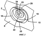
фигура 3: увеличенный фрагмент фигуры 1.figure 3: an enlarged fragment of figure 1.
фигура 4: разрез установленной на сквозной проход крышки согласно первому варианту исполнения изобретения.figure 4: sectional view of a lid mounted on a through passage according to a first embodiment of the invention.
фигура 5: крышка согласно второму варианту исполнения изобретения.Figure 5: Cover according to a second embodiment of the invention.
фигура 6: перспективный вид фрагмента дверки холодильного аппарата согласно третьему варианту исполнения изобретения.figure 6: perspective view of a fragment of a door of a refrigerator according to a third embodiment of the invention.
Осуществление изобретенияThe implementation of the invention
На фигуре 1 показан встраиваемый холодильный аппарат с корпусом 1 и подвешенной на корпусе 1, показанной в частично открытом положении дверкой 2. На задней стороне дверки, скрытой от наблюдателя, находится известное само по себе и не показанное на фигуре магнитное уплотнение, которое в закрытом положении дверки в значительной степени герметично прилегает к передней стороне 3 корпуса. Таким образом, когда воздух охлаждается во внутренней полости 4 холодильного аппарата, внутри возникает пониженное давление, которое будет с большой силой прижимать дверку 2 к передней стороне 3, если не будут приняты меры по выравниванию давления между внутренней полостью 4 и окружающей средой.Figure 1 shows a built-in refrigeration unit with a
Для осуществления такого выравнивания давления уравнительный клапан 5 устанавливается в верхней части дверки в несколько внецентровом положении. На собранном холодильном аппарате клапан не виден, так как дверка 2 будет скрыта не показанной на фигуре 1 декоративной панелью. Эта декоративная панель крепится на расстоянии нескольких миллиметров от дверки 2 благодаря чему не препятствует притоку воздуха к уравнительному клапану 5.To achieve this pressure equalization, the equalizing
На фигуре 2 уравнительный клапан 5 и его окружение представлено частично в разрезе, а частично - в перспективном виде. Участок металлической внешней оболочки дверки обозначен цифрой 6. Внутренняя оболочка выполнена методом глубокой вытяжки из пластмассы и плотно соединена своими кромками, не показанными на фигуре, с листом внешней оболочки. Участок стенки внутренней полости обозначен цифрой 7.In figure 2, equalizing
На дне выполненного в стенке внутренней полости углубления 8 выполнено отверстие 9, имеющее форму круга с двумя вырезанными сегментами на противоположных сторонах. Через отверстие 9 перед соединением стенки 7 внутренней полости с внешней оболочкой 6 со стороны, скрытой от взгляда наблюдателя, вводится и фиксируется первая гильза 10. Гильза 10 на своей оконечности, обращенной к наблюдателю, имеет фланец 11, который, как и отверстие 9, имеет форму круга с двумя вырезанными сегментами по бокам. Благодаря этому фланец, будучи повернут на 90° относительно показанного на фигуре положения, проходит через отверстие 9, после чего фиксируется в отверстии в показанном на фигуре положении.At the bottom of the
На стенках углубления 8 показаны фиксирующие насечки 26, предназначенные для крепления не показанной на фигуре 2 крышки. В альтернативном варианте такие фиксирующие насечки или фиксирующие выступы могут быть сформированы на гильзе 10, в частности на ее фланце 11.On the walls of the
Стенка 7 внутренней полости в показанной конфигурации зажимается между фланцем 11 и кольцевым фланцем 12, который эластично прижимается к той стороне стенки 7 внутренней полости, которая обращена в сторону внешней оболочки. Внешний диаметр кольцевого фланца 12 превышает диаметр отверстия 9, поэтому изоляционный материал (не показанный на фигуре 2), заполняющий промежуточное пространство между внешней оболочкой 6 и стенкой 7 внутренней полости, не может проникнуть в отверстие 9.The
Второй кольцевой фланец 13 с диаметром, меньшим диаметра первого кольцевого фланца 12, сформирован на гильзе 10 рядом с ее оконечностью, обращенной к внешней оболочке 6. Этот кольцевой фланец 13 эластично прилегает к внутренней стороне конически расширяющегося участка 14 второй гильзы 15. Гильза 15 крепится к внешней оболочке 6 аналогично гильзе 10, причем она зажимает внешнюю оболочку между прилегающим к наружной стороне внешней оболочки 6 фланцем 16 и прилегающим к внутренней стороне эластичным кольцевым фланцем 17. Эластичность кольцевого фланца 13 во время монтажа позволяет сдвинуть две гильзы 10, 15 друг к другу, что позволит подстроиться под различную толщину дверки.A second
Гильза 15 также монтируется на внешней оболочке 6 перед ее соединением со стенкой 7 внутренней полости. Когда внешняя оболочка 6 и стенка 7 внутренней полости будут соединены между собой, расширенный участок 14 облегчит введение гильзы 10 в гильзу 15.The
К участку 14 примыкает короткий цилиндрический участок 18 гильзы 15, который фиксирует гильзу 10 с геометрическим замыканием.A short
Свободная оконечность гильзы 10 достигает чашеобразного расширения 19 гильзы 15, которое примыкает к цилиндрическому участку 18 и содержит фланец 16 и кольцевой фланец 17.The free end of the
Кольцевой фланец 13 гильзы 10, будучи вставленным в конусообразный участок 14, эластично выгибается таким образом, что обращенная в сторону изоляционного материала поверхность кольцевого фланца 13 приобретает вогнутую форму. Благодаря этому кольцевой фланец 13 под влиянием давления, действующего на него во время заполнения пеной полости между внешней оболочкой 6 и стенкой 7 внутренней полости, прижимается к конусообразному участку 14, что еще более улучшает герметизирующее действие кольцевого фланца 13.The
Внутренняя часть гильзы 10 диаметрально разделена продольной стенкой 20. На продольной стенке 20 сверху установлен эластичный пластмассовый лист 21. Лист 21 имеет в целом эллиптическую форму, то есть его кромки на всем своем протяжении могут плотно прилегать к гильзе 10. Когда во внутренней полости 4 возникает пониженное давление, кромки листа 21 прижимаются к продольной стенке 20 и воздух может поступать снаружи вовнутрь. Возможное повышенное давление во внутренней полости 4 действует на всю поверхность листа 21 и прижимает его в направлении наружу и/или к гильзе 10. Накидная деталь 22, зафиксированная на свободной оконечности гильзы 10 при помощи не показанного на фигуре байонетного соединения, не позволяет листу 21 быть выдавленным из гильзы 10 под действием внутреннего повышенного давления. Это происходит, во-первых, за счет того, что накидная деталь 22 сужает свободное сечение гильзы 10, а во-вторых, благодаря поперечине 23, которая простирается по диаметру центрального отверстия 24 накидной детали 22.The inner part of the
На внешнем виде клапана, представленном на фигуре 3, видно расширение 19 гильзы 15 с прилегающим к наружной стороне внешней оболочки 6 фланцем 16, фрагмент отверстия 25 внешней оболочки, в которое вставлена гильза 15, а также накидная деталь 22 внутри расширения 19.On the appearance of the valve, shown in figure 3, you can see the
На фигуре 4 представлен фрагмент стенки 7 внутренней полости с углублением 8, часть гильзы 10 и крышка 27 согласно первому варианту исполнения. Крышка 27 в данном случае представляет собой круглую, твердую, соответствующую форме углубления 8 пластину 28, с обратной стороны которой выступают фиксирующие выступы 29 и распорки 30. Фиксирующие выступы 29 зацепляются за фиксирующие насечки 26 углубления 8, причем распорки 30, соприкасающиеся со стенкой 7 внутренней полости по окружности углубления 8, обеспечивают открытый зазор по окружности кромки углубления 8. Ширина зазора 31 в размере нескольких миллиметров достаточна для обеспечения беспрепятственного распространения поступившего через гильзу 10 во время процесса выравнивания давления воздуха. С другой стороны, конвекционные потоки, движущиеся вдоль стенки 7 внутренней полости, не допускаются в углубление 8.The figure 4 presents a fragment of the
Согласно варианту, представленному на фигуре 5, перед углублением 8 установлена крышка 27' в форме решетки. Решетка 27' прилегает непосредственно к стенке 7 внутренней полости и фиксируется при помощи фиксирующих выступов 29' (имеющих форму шпильки), зацепляющихся за фиксирующие насечки 26. Решетка содержит множество расположенных под углом ребер 32, между которыми может свободно проходить воздух, прошедший через уравнительный клапан. Эти ребра, при взгляде изнутри, перекрывают эластичный лист 21 уравнительного клапана 5 и скрывают обледенение листа 21, которого не удается полностью избежать при нормальной эксплуатации аппарата.According to the embodiment of FIG. 5, a grill-shaped lid 27 'is installed in front of the
Ребра 32 могли бы быть ориентированы и по горизонтали, чтобы свести к минимуму влияние на воздушный поток, поступающий во внутреннюю полость из уравнительного клапана; также они помогают скрыть обледенение листа 21, так как они маскируют внутреннюю часть гильзы 10.The
Еще один вариант исполнения изобретения показан на фигуре 6, которая представляет собой перспективный вид внутренней стороны дверки 2 холодильного аппарата. Дверка 2, показанная на этой фигуре, относится к холодильному аппарату, внутренняя полость которого разделена на две камеры, температурный режим в которых может устанавливаться по отдельности благодаря циркуляции холодного воздуха. Камера испарителя (источник холодного воздуха) расположена под крышкой корпуса холодильного аппарата и снабжает холодным воздухом верхнюю камеру для хранения продуктов напрямую, а нижнюю камеру для хранения продуктов через проложенный в задней стенке корпуса воздуховод. Обратный воздуховод, по которому воздух из нижней камеры для хранения продуктов поступает обратно в камеру испарителя, проложен вертикально внутри дверки 2 и на своей верхней оконечности имеет выпускное отверстие 33, которое при закрытой дверке располагается напротив впускного отверстия камеры испарителя. Выпускное отверстие 33 окружено отлитой из пластмассы рамкой 34, которая зафиксирована на внутренней стенке 35 дверки или закреплена любым другим подходящим способом. Размеры рамки 34 значительно превышают размеры выпускного отверстия 33; рамка перекрывает также сквозной проход, в который помещен уравнительный клапан 5. Соответственно, в закрытой в остальном пластине рамки 34 сформировано два окна: одно, соответствующее выпускному отверстию 33, и второе 36, за которым находится сквозной проход с уравнительным клапаном 5. Оба окна сделаны незаметными благодаря шаблону с параллельными горизонтальными ребрами 37, который закрывает в целом всю площадь рамки вместе с сформированными в ней окнами и выполняет, таким образом, функцию ребер 32 с фигуры 5 для окна 36 уравнительного клапана.Another embodiment of the invention is shown in figure 6, which is a perspective view of the inner side of the
Claims (7)
Applications Claiming Priority (2)
| Application Number | Priority Date | Filing Date | Title |
|---|---|---|---|
| DE200710021600 DE102007021600A1 (en) | 2007-05-08 | 2007-05-08 | Housing for a refrigeration device |
| DE102007021600.0 | 2007-05-08 |
Publications (2)
| Publication Number | Publication Date |
|---|---|
| RU2009142883A RU2009142883A (en) | 2011-06-20 |
| RU2463532C2 true RU2463532C2 (en) | 2012-10-10 |
Family
ID=39829271
Family Applications (1)
| Application Number | Title | Priority Date | Filing Date |
|---|---|---|---|
| RU2009142883/13A RU2463532C2 (en) | 2007-05-08 | 2008-04-29 | Refrigerating device housing |
Country Status (5)
| Country | Link |
|---|---|
| EP (1) | EP2156113A2 (en) |
| CN (1) | CN101688722A (en) |
| DE (1) | DE102007021600A1 (en) |
| RU (1) | RU2463532C2 (en) |
| WO (1) | WO2008135472A2 (en) |
Families Citing this family (3)
| Publication number | Priority date | Publication date | Assignee | Title |
|---|---|---|---|---|
| CN103673468B (en) * | 2012-09-26 | 2016-03-30 | 海尔集团公司 | Refrigerator |
| CN103900326B (en) * | 2012-12-26 | 2016-06-29 | 海尔集团公司 | A kind of keep the device of refrigerator internal and external pressure balance, installation method and refrigerator |
| CN105157321A (en) * | 2015-08-18 | 2015-12-16 | 合肥华凌股份有限公司 | Ventilated frost reduction device, door body and freezer with door body |
Citations (2)
| Publication number | Priority date | Publication date | Assignee | Title |
|---|---|---|---|---|
| RU2045716C1 (en) * | 1992-08-26 | 1995-10-10 | Омское научно-производственное объединение "Сибкриотехника" | Portable refrigerator and method of its operation |
| DE10233216A1 (en) * | 2002-07-22 | 2004-02-12 | BSH Bosch und Siemens Hausgeräte GmbH | Cooling device, especially wine storage cabinet or refrigerator, with moisture feed has thermally insulating housing with body, door, passage for external air to enter internal volume when door closed |
Family Cites Families (7)
| Publication number | Priority date | Publication date | Assignee | Title |
|---|---|---|---|---|
| GB1408006A (en) * | 1971-11-22 | 1975-10-01 | Fermod | Device for communicating with free air in particular for cold room |
| IT1126138B (en) * | 1979-12-04 | 1986-05-14 | Silvana Maccari | PRESSURE COMPENSATING VALVE PARTICULARLY FOR HOT OR COLD ISOTHERMAL CELLS |
| DE8815739U1 (en) | 1988-12-19 | 1989-02-02 | Viessmann Gmbh & Co, 8670 Hof, De | |
| SI9600364A (en) * | 1996-12-11 | 1998-06-30 | Gorenje Gospodinjski Aparati D.D. | Device for pressure equalisation, particularly for freezers |
| DE10203425A1 (en) * | 2002-01-28 | 2003-08-07 | Horst Baehring | Freezer cabinet with pressure equalization has arrangement on body or door of cabinet for producing pressure balance between inner chamber and surroundings of cabinet |
| US20050081555A1 (en) * | 2003-10-20 | 2005-04-21 | Seiss Richard A. | Relief port |
| ITMI20040115A1 (en) * | 2004-01-28 | 2004-04-28 | Whirlpool Co | COMPENSATING VALVE FOR FREEZERS |
-
2007
- 2007-05-08 DE DE200710021600 patent/DE102007021600A1/en not_active Withdrawn
-
2008
- 2008-04-29 RU RU2009142883/13A patent/RU2463532C2/en not_active IP Right Cessation
- 2008-04-29 EP EP08749880A patent/EP2156113A2/en not_active Withdrawn
- 2008-04-29 CN CN200880014907A patent/CN101688722A/en active Pending
- 2008-04-29 WO PCT/EP2008/055281 patent/WO2008135472A2/en active Application Filing
Patent Citations (2)
| Publication number | Priority date | Publication date | Assignee | Title |
|---|---|---|---|---|
| RU2045716C1 (en) * | 1992-08-26 | 1995-10-10 | Омское научно-производственное объединение "Сибкриотехника" | Portable refrigerator and method of its operation |
| DE10233216A1 (en) * | 2002-07-22 | 2004-02-12 | BSH Bosch und Siemens Hausgeräte GmbH | Cooling device, especially wine storage cabinet or refrigerator, with moisture feed has thermally insulating housing with body, door, passage for external air to enter internal volume when door closed |
Also Published As
| Publication number | Publication date |
|---|---|
| DE102007021600A1 (en) | 2008-11-13 |
| WO2008135472A2 (en) | 2008-11-13 |
| WO2008135472A3 (en) | 2009-01-22 |
| RU2009142883A (en) | 2011-06-20 |
| CN101688722A (en) | 2010-03-31 |
| EP2156113A2 (en) | 2010-02-24 |
Similar Documents
| Publication | Publication Date | Title |
|---|---|---|
| RU2402723C1 (en) | Refrigerating device with opening for pressure balancing | |
| CA2206506C (en) | Refrigerator mullion | |
| KR102186861B1 (en) | Refrigerator | |
| TWI392841B (en) | Refrigerator | |
| US20180187951A1 (en) | Refrigerator | |
| CN203534032U (en) | Drainpipe used for refrigerator, and refrigerator | |
| MX2008000566A (en) | Air blowing arrangement for a combined refrigerator. | |
| KR101998566B1 (en) | Refrigerator | |
| RU2463532C2 (en) | Refrigerating device housing | |
| RU2010113566A (en) | AIR FILTER AND REFRIGERATOR WITH AIR FILTER | |
| JP5008513B2 (en) | Cooling storage | |
| KR100804608B1 (en) | Door assembly and kimchi-storage having a wine-storage thereof | |
| US3311045A (en) | Vent breather for refrigerator | |
| EP3070422B1 (en) | Refrigerator | |
| TR201721428T3 (en) | A fridge. | |
| EP4000468A1 (en) | Cold storage | |
| JP4934516B2 (en) | Cooling storage | |
| CN102016460A (en) | Refrigeration device comprising a pressure compensation valve | |
| US20160076802A1 (en) | Freezer, in particular ultra-low temperature freezer | |
| JP2010169346A (en) | Cooling storage | |
| JP6737437B2 (en) | refrigerator | |
| RU2512324C2 (en) | Refrigerating unit | |
| EP3845836B1 (en) | Entrance refrigerator | |
| KR200390003Y1 (en) | The kimchi-refrigerator having small door | |
| JPH07218112A (en) | Refrigerator |
Legal Events
| Date | Code | Title | Description |
|---|---|---|---|
| PD4A | Correction of name of patent owner | ||
| MM4A | The patent is invalid due to non-payment of fees |
Effective date: 20160430 |