RU2463379C2 - Method of galvanisation by submersion of steel strip - Google Patents
Method of galvanisation by submersion of steel strip Download PDFInfo
- Publication number
- RU2463379C2 RU2463379C2 RU2010137276/02A RU2010137276A RU2463379C2 RU 2463379 C2 RU2463379 C2 RU 2463379C2 RU 2010137276/02 A RU2010137276/02 A RU 2010137276/02A RU 2010137276 A RU2010137276 A RU 2010137276A RU 2463379 C2 RU2463379 C2 RU 2463379C2
- Authority
- RU
- Russia
- Prior art keywords
- temperature
- strip
- tank
- liquid mixture
- preparation device
- Prior art date
Links
Images


Abstract
Description
Настоящее изобретение касается способа цинкования погружением стальной полосы, характеризованного в ограничительной части пункта 1 формулы изобретения.The present invention relates to a method of galvanizing by immersion of a steel strip, characterized in the restrictive part of
Цинкование погружением непрерывно движущегося стального полосового проката является известной технологией, которая в основном содержит два варианта, в одном из которых полосу, выходящую из цинковальной печи, опускают под углом в ванну жидкого металла, содержащую, по меньшей мере, один металл, предназначенный для цинкования, такой как цинк, алюминий, а затем отклоняют вертикально вверх при помощи ролика, погруженного в упомянутую ванну жидкого металла. В другом варианте полосу отклоняют вертикально вверх на выходе из печи и затем перемещают в вертикальном канале, содержащем расплавленный цинк, удерживаемый за счет магнитной левитации. Ванна жидкого металла представляет собой цинковый сплав с переменными количествами алюминия, магния или марганца. Для упрощения патента описание касается только случая использования сплава цинка и алюминия.Immersion galvanizing of continuously moving steel strip steel is a known technology, which basically contains two options, in one of which the strip exiting the galvanizing furnace is lowered at an angle into a molten metal bath containing at least one galvanized metal, such as zinc, aluminum, and then deflected vertically upwards by means of a roller immersed in said molten metal bath. In another embodiment, the strip is deflected vertically upstream of the furnace and then moved in a vertical channel containing molten zinc held by magnetic levitation. A liquid metal bath is a zinc alloy with varying amounts of aluminum, magnesium, or manganese. To simplify the patent, the description only applies to the use of an alloy of zinc and aluminum.
В обоих случаях операция предназначена для выполнения на поверхности стальной полосы сплошного и плотно прилегающего покрытия из жидкой смеси цинка и алюминия, в которой перемещается упомянутая полоса. Кинетика формирования этого покрытия хорошо известна специалистам и раскрыта во многих публикациях, в том числе “Modeling of galvanizing reactions” Georgi et al., “La Revue de Métallurgie-CIT”, октябрь 2004 г. Согласно этому источнику, при контакте с жидкой смесью происходит растворение железа из стальной полосы, которое, с одной стороны, участвует в формировании на поверхности полосы комбинированного слоя соединения Fe2Al3Znx толщиной около 0,1 мкм и, с другой стороны, диффундирует в направлении ванны жидкого металла, пока не образуется сплошной слой Fe2Al3Znx. Слой Fe2Al3Znx служит подложкой для конечного защитного слоя цинка, тогда как растворенное железо способствует образованию в жидкой смеси осаждений, состоящих из железа Fe, алюминия Al и цинка Zn и называемых «штейнами» или «дроссами». Эти осаждения в виде частиц в несколько микрон могут привести к появлению на полосе с покрытием (оцинкованной полосе) поверхностных дефектов, которые могут быть неисправимыми, в частности, если речь идет о стальных полосах, предназначенных для выполнения внешних кузовных элементов автомобиля. Металлурги приложили немало усилий, чтобы ограничить или исключить образование дроссов в ваннах для цинкования. Явление образования дроссов известно специалистам, например, из публикации “Numerical simulation of the rate of dross formation in continuous galvanizing baths” Ajersch et al. В зависимости от температуры ванны жидкого цинка и от содержания в ней алюминия количество железа, которое может раствориться, колеблется в достаточно широких пределах. Когда содержание железа превышает предел растворимости, становятся возможными образование зародышей и рост определенных соединений Fe-Al-Zn. В обычных процессах непрерывного цинкования цинковальная ванна, содержащая жидкую смесь, предназначенную для нанесения на полосу, остается постоянно насыщенной железом, в результате чего все железо, растворенное из полосы и диффундирующее в жидкую смесь, немедленно участвует в локальном образовании дроссов.In both cases, the operation is designed to perform on the surface of the steel strip a continuous and tight-fitting coating of a liquid mixture of zinc and aluminum, in which the said strip is moved. The kinetics of the formation of this coating is well known to those skilled in the art and has been disclosed in many publications, including “Modeling of galvanizing reactions” by Georgi et al., “La Revue de Métallurgie-CIT”, October 2004. According to this source, contact with a liquid mixture occurs the dissolution of iron from a steel strip, which, on the one hand, is involved in the formation of a combined layer of a Fe 2 Al 3 Zn x compound about 0.1 μm thick on the strip surface and, on the other hand, diffuses in the direction of the molten metal bath until it forms a solid layer Fe 2 Al 3 Zn x . The Fe 2 Al 3 Zn x layer serves as a substrate for the final zinc protective layer, while dissolved iron contributes to the formation of precipitates in the liquid mixture consisting of Fe iron, aluminum Al and zinc Zn and called “mattes” or “drosses”. These depositions in the form of particles of several microns can lead to the appearance of surface defects on the coated strip (galvanized strip), which can be irreparable, in particular, if we are talking about steel strips designed to perform external car body elements. Metallurgists made a lot of efforts to limit or eliminate the formation of dross in galvanizing baths. The phenomenon of the formation of drosses is known to specialists, for example, from the publication “Numerical simulation of the rate of dross formation in continuous galvanizing baths” Ajersch et al. Depending on the temperature of the liquid zinc bath and on the aluminum content in it, the amount of iron that can dissolve varies widely. When the iron content exceeds the solubility limit, nucleation and growth of certain Fe-Al-Zn compounds become possible. In conventional continuous galvanizing processes, a galvanizing bath containing a liquid mixture intended to be applied to the strip remains continuously saturated with iron, as a result of which all the iron dissolved from the strip and diffusing into the liquid mixture immediately participates in the local formation of drosses.
Среди средств, предусмотренных для контроля за образованием дроссов или, по меньшей мере, для сокращения их количества в цинковальной ванне, уже давно прибегают к ручному снятию затвердевших частей расплава с поверхности жидкой смеси. Этот способ справедливо считают опасным для операторов, и эту операцию снятия затвердевших частей было предложено механизировать, а затем и роботизировать, как описано в документе JP 2001-064760.Among the means provided for controlling the formation of drosses, or at least to reduce their number in a zinc bath, they have long resorted to the manual removal of hardened parts of the melt from the surface of the liquid mixture. This method is rightly considered dangerous for operators, and it was proposed to mechanize and then robotize this hardened part removal operation, as described in JP 2001-064760.
Для удаления дроссов, образующихся в цинковальной ванне, были предложены и другие методы, использующие перелив, откачку или выбросы. Так, в документе ЕР 1070765 описан ряд вариантов цинковальной установки, содержащей, кроме цинковального бака, в котором образуются дроссы, вспомогательный бак, в который удаляют дроссы.Other methods using overflow, pumping, or emissions have been proposed to remove the dross generated in the zinc bath. So, in document EP 1070765 describes a number of options galvanizing installation, containing, in addition to the galvanizing tank, which forms dross, an auxiliary tank, which remove dross.
В документе ЕР 0429351 авторы изобретения пошли еще дальше и предложили способ и устройство для создания циркуляции жидкой смеси металла между зоной нанесения покрытия на металлическую полосу и зоной очистки цинковальной ванны, содержащей жидкий цинк, для обеспечения отделения дроссов в зоне очистки и для доставки в зону цинкования жидкой смеси, «содержание железа в которой близко или ниже предела растворимости». Однако, описав действующие физические принципы, этот документ не дает никакого указания, позволяющего специалисту применить эти принципы, в частности, каким образом одновременно контролировать охлаждение при помощи теплообменника и индукционный нагрев одной и той же зоны очистки. Документ не содержит также никакого указания на средство для определения расхода циркуляции жидкого цинка.In EP 0429351, the inventors went even further and proposed a method and apparatus for circulating a liquid metal mixture between a coating zone on a metal strip and a cleaning zone of a zinc bath containing liquid zinc, to ensure separation of the dross in the cleaning zone and for delivery to the galvanizing zone liquid mixture, "the iron content of which is close to or below the solubility limit." However, having described the current physical principles, this document does not give any indication allowing a specialist to apply these principles, in particular, how to simultaneously control cooling by means of a heat exchanger and induction heating of the same cleaning zone. The document also does not contain any indication of a means for determining the flow rate of liquid zinc.
Настоящее изобретение призвано предложить способ цинкования погружением стальной полосы в жидкую смесь, в котором контур циркуляции жидкой смеси является термически оптимизированным.The present invention is intended to provide a galvanizing method by immersion of a steel strip in a liquid mixture, in which the circulation circuit of the liquid mixture is thermally optimized.
Такой способ можно применять с использованием методики, предложенной в пункте 1 формулы изобретения.This method can be applied using the methodology proposed in
Для более наглядной иллюстрации аспектов предложенного способа в соответствии с настоящим изобретением на фиг. 1 и 2 показана установка для цинкования погружением стальной полосы в жидкую смесь и один из ее вариантов, позволяющих применять предложенный способ.To more clearly illustrate aspects of the proposed method in accordance with the present invention in FIG. 1 and 2 show the installation for galvanizing by immersion of a steel strip in a liquid mixture and one of its variants, allowing to apply the proposed method.
Фиг. 1 - принципиальная схема установки, в которой применяют предложенный способ.FIG. 1 is a schematic diagram of an installation in which the proposed method is used.
Фиг. 2 - принципиальная схема варианта установки, в которой применяют предложенный способ.FIG. 2 is a schematic diagram of an installation option in which the proposed method is used.
На фиг. 1 показана принципиальная схема установки для применения способа в соответствии с настоящим изобретением. Стальную полосу (1) подают в установку, в идеальном варианте - непрерывно, вводя ее под углом в цинковальный бак (2) через канал (3) соединения с цинковальной печью (на фигуре не показана и находится перед цинковальным баком). Полосу отклоняют вертикально при помощи ролика (4) и пропускают через жидкую смесь (5) покрытия, содержащуюся в упомянутом цинковальном баке. Отклонение полосы можно осуществлять при помощи горизонтального ролика (4), сопровождающего перемещение полосы. Канал (6) обеспечивает перетекание излишков жидкой смеси в устройство (7) подготовки, содержащее две зоны: первую зону (71), в которой обеспечивают расплавление, по меньшей мере, одного слитка сплава (8) Zn-Al в количестве, достаточном для восполнения жидкой смеси, расходуемой при осаждении на полосу в цинковальном баке и при неизбежных потерях (материальных), и вторую зону (72), находящуюся сразу за первой зоной по направлению потока жидкой смеси (цинковальный бак, затем первая зона, затем вторая зона). Эти две зоны могут находиться в одном баке, как показано на фиг. 1, и в этом случае они разделены разделительным устройством (73), таким как стенка, открытая в своей центральной части, или могут представлять собой два отдельных бака, установленных рядом друг с другом. Между этими двумя отдельными и находящимися рядом баками жидкую смесь можно перемещать при помощи откачки или через соединительный канал. Предпочтительно уровень начала откачки в первой зоне (71) или входной уровень соединительного канала находятся между верхней зоной (81) отделения поверхностных дроссов и нижней зоной (82) осаждения донных дроссов, то есть в центральной трети высоты зоны (71). Действительно, согласно способу в соответствии с настоящим изобретением, на этой центральной высоте устройства подготовки можно выделить промежуточное пространство, свободное от дроссов, между двумя зонами, нижней и верхней, для скапливания (постепенно увеличивающегося по направлению потока (FL)) упомянутых дроссов (81, 82).In FIG. 1 shows a schematic diagram of an apparatus for applying the method in accordance with the present invention. The steel strip (1) is fed into the installation, ideally, continuously, introducing it at an angle into the galvanizing tank (2) through the channel (3) of the connection to the galvanizing furnace (not shown in the figure and is located in front of the galvanizing tank). The strip is deflected vertically by means of a roller (4) and passed through the liquid mixture (5) of the coating contained in said zinc tank. The deviation of the strip can be carried out using a horizontal roller (4), accompanying the movement of the strip. Channel (6) allows the excess liquid mixture to flow into the preparation device (7) containing two zones: the first zone (71), in which at least one ingot of Zn-Al alloy (8) is melted in an amount sufficient to make up liquid mixture consumed during deposition onto a strip in a zinc tank and inevitable losses (material), and a second zone (72) located immediately after the first zone in the direction of flow of the liquid mixture (zinc tank, then the first zone, then the second zone). These two zones can be in the same tank, as shown in FIG. 1, and in this case they are separated by a separation device (73), such as a wall open in its central part, or can be two separate tanks installed next to each other. Between these two separate and adjacent tanks, the liquid mixture can be moved by pumping or through the connecting channel. Preferably, the level of the start of pumping in the first zone (71) or the input level of the connecting channel is between the upper zone (81) of separating the surface dams and the lower zone (82) of sedimentation of bottom drosses, i.e. in the central third of the height of the zone (71). Indeed, according to the method in accordance with the present invention, at this central height of the preparation device, it is possible to allocate an intermediate space free of drosses between two zones, lower and upper, for accumulating (gradually increasing in the direction of flow (FL)) of said drosses (81, 82).
Выходящая из цинковального бака жидкая смесь имеет достаточно высокую температуру для плавления слитка. Расход энергии для плавления слитка приводит к охлаждению жидкой смеси, в результате которого образуются поверхностные (81) и донные (82) дроссы, задерживаемые герметичными частями на выходе устройства подготовки (73). Между цинковальным баком и устройством подготовки, например на их соединительном канале (6), можно расположить средство (62) дополнительного охлаждения с эффектом охлаждения за счет расходования слитков. Во вторую зону (72) устройства подготовки проходит очищенная жидкая смесь, которую можно нагреть при помощи средства (75) нагрева, предпочтительно индукционного нагрева. Патрубок (9) отбирает жидкую смесь во второй зоне (72) и в случае, показанном на фиг. 1, при помощи устройства (10) откачки и патрубка (11) обратного потока обеспечивает повторное питание цинковального бака (2) через желоб (12) в зависимости от расхода очищенной жидкой смеси. Устройства, например, такие как системы снятия затвердевших частей или откачки позволяют удалять дроссы из устройства подготовки (первая зона (71)). Предпочтительно первая зона (71) устройства подготовки может содержать перегородки, разделяющие порции жидкой смеси и находящиеся между несколькими слитками (8), последовательно расположенными в направлении потока. Эти перегородки можно выполнить в виде стенки, открытой в своей центральной части, что позволяет концентрировать донные (82) и поверхностные (81) дроссы для каждого слитка в зависимости от содержания в них алюминия.The liquid mixture emerging from the zinc tank has a sufficiently high temperature to melt the ingot. The energy consumption for melting the ingot leads to cooling of the liquid mixture, which results in the formation of surface (81) and bottom (82) drosses, delayed by the sealed parts at the outlet of the preparation device (73). Between the zinc tank and the preparation device, for example, on their connecting channel (6), it is possible to place means (62) for additional cooling with the cooling effect due to the consumption of ingots. A purified liquid mixture passes into the second zone (72) of the preparation device, which can be heated using heating means (75), preferably induction heating. The nozzle (9) draws the liquid mixture in the second zone (72) and in the case shown in FIG. 1, by means of a pumping device (10) and a return flow pipe (11), it is possible to re-supply the zinc tank (2) through the chute (12) depending on the flow rate of the purified liquid mixture. Devices, for example, such as systems for removing hardened parts or pumping out, allow the dross to be removed from the preparation device (first zone (71)). Preferably, the first zone (71) of the preparation device may comprise partitions separating portions of the liquid mixture and located between several ingots (8) sequentially located in the flow direction. These partitions can be made in the form of a wall open in its central part, which allows one to concentrate bottom (82) and surface (81) drosses for each ingot depending on the aluminum content in them.
Что касается процесса плавления слитков, первая зона (71) устройства подготовки предпочтительно содержит несколько слитков (81, 82, …, 8n), по меньшей мере, два из которых имеют разное содержание алюминия, и, по меньшей мере, один из слитков имеет содержание выше, чем требуемое содержание в жидкой смеси в устройстве подготовки. Кроме того, первая зона (71) устройства подготовки содержит средство регулирования расхода плавления, по меньшей мере, двух слитков, предпочтительно путем селективного погружения или извлечения, по меньшей мере, одного слитка в первой зоне (71). Наконец, первый отсек устройства подготовки может содержать средство (6, 62) регулирования заранее определенного понижения температуры (Т2, Т3) жидкой смеси, в которой плавятся слитки, предпочтительно тоже путем селективного погружения или извлечения, по меньшей мере, одного слитка в первой зоне (71).Regarding the process of melting the ingots, the first zone (71) of the preparation device preferably contains several ingots (8 1 , 8 2 , ..., 8 n ), at least two of which have different aluminum contents, and at least one of the ingot has a content higher than the required content in the liquid mixture in the preparation device. In addition, the first zone (71) of the preparation device comprises means for controlling the melting rate of at least two ingots, preferably by selectively dipping or removing at least one ingot in the first zone (71). Finally, the first compartment of the preparation device may comprise means (6, 62) for regulating a predetermined lowering of the temperature (T2, T3) of the liquid mixture in which the ingots are melted, preferably also by selective immersion or extraction of at least one ingot in the first zone ( 71).
В свете этого решения непрерывное плавление слитков (8) в устройстве подготовки обеспечивается при общем расходе плавления, по меньшей мере, двух слитков. В этом случае в ванну жидкой смеси предпочтительно одновременно погружают набор из n слитков, при этом каждый из них имеет разное содержание алюминия, при этом, по меньшей мере, один из них имеет содержание алюминия выше, чем требуемое содержание в устройстве подготовки, чтобы установить профиль содержания (или расход плавления), изменяющийся во времени. Само это требуемое содержание определяют на основании измеряемого или оцениваемого расхода алюминия в цинковальном баке в комбинированном слое Fe2Al3Znx, образующемся на поверхности полосы, и в дроссах, образующихся в устройстве подготовки. Предпочтительно расход плавления каждого из n слитков можно также контролировать индивидуально таким образом, чтобы доводить содержание алюминия в устройстве подготовки до требуемого значения, сохраняя при этом общую требуемую скорость плавления.In light of this solution, continuous melting of the ingots (8) in the preparation device is ensured at a total melting rate of at least two ingots. In this case, a set of n ingots is preferably simultaneously immersed in the bath of the liquid mixture, each of them having a different aluminum content, with at least one of them having an aluminum content higher than the required content in the preparation device in order to establish the profile content (or melting rate) that varies over time. This required content itself is determined on the basis of the measured or estimated consumption of aluminum in the zinc tank in the combined Fe 2 Al 3 Zn x layer formed on the strip surface and in the drosses formed in the preparation device. Preferably, the melting rate of each of the n ingots can also be individually controlled in such a way as to bring the aluminum content in the preparation device to the desired value, while maintaining the overall required melting rate.
Непрерывное плавление слитков в устройстве подготовки приводит к локальному охлаждению жидкой смеси со второй температуры (на выходе цинковального бака) до заранее определенной температуры в первой зоне (71) с целью снижения порога растворимости железа и обеспечения локального формирования дроссов в упомянутом устройстве подготовки не выше порога растворимости при заранее определенной температуре. Так называемые «поверхностные» дроссы с высоким содержанием алюминия преимущественно образуются вблизи погруженных слитков с высоким содержанием алюминия, затем всплывают на поверхность, а так называемые «донные» дроссы с высоким содержанием цинка преимущественно образуются вблизи погруженных слитков с низким содержанием алюминия, затем осаждаются на дно.Continuous melting of the ingots in the preparation device leads to local cooling of the liquid mixture from the second temperature (at the outlet of the galvanizing tank) to a predetermined temperature in the first zone (71) in order to reduce the solubility threshold of iron and ensure local formation of dross in the said preparation device not higher than the solubility threshold at a predetermined temperature. The so-called “surface” drosses with a high aluminum content mainly form near submerged ingots with a high aluminum content, then float to the surface, and the so-called “bottom” drosses with a high aluminum content predominantly form near submerged ingots with a high aluminum content, then settle to the bottom .
После образования дроссов рециркуляционный поток жидкой смеси, поступающий в цинковальный бак, при содержании железа, равном порогу растворимости железа при заранее определенной температуре, позволяет ограничить содержание растворенного железа значением ниже порога растворимости при второй температуре.After the formation of drosses, the recirculation flow of the liquid mixture entering the zinc tank, when the iron content is equal to the solubility threshold of iron at a predetermined temperature, allows you to limit the content of dissolved iron to a value below the solubility threshold at the second temperature.
Таким образом, устройство (7) подготовки может содержать только один бак, состоящий из двух зон (71, 72), разделенных разделительной стенкой (73), при этом первая зона обеспечивает плавление слитков и локализует образование дроссов, а во вторую зону поступает очищенная жидкая смесь. В этом случае вторую зону оборудуют единственным и простым средством (75) индукционного нагрева, обеспечивающим нагрев очищенной жидкой смеси перед ее повторной подачей в цинковальный бак, чтобы замкнуть термический цикл обратного потока в конце пути потока на начало нового потока. Две зоны (71) и (72) могут также находиться в двух отдельных баках, соединенных соединительным каналом.Thus, the preparation device (7) can contain only one tank, consisting of two zones (71, 72), separated by a dividing wall (73), while the first zone provides melting of the ingots and localizes the formation of dross, and the purified liquid enters the second zone mixture. In this case, the second zone is equipped with a single and simple means (75) of induction heating, which ensures heating of the purified liquid mixture before it is again fed to the zinc tank to close the thermal cycle of the reverse flow at the end of the flow path to the beginning of a new flow. Two zones (71) and (72) can also be located in two separate tanks connected by a connecting channel.
На фиг. 2 показан вариант принципиальной схемы установки, показанной на фиг. 1, в котором первоначальный цинковальный бак разделен на бак (15) отклонения полосы (без жидкой смеси) и на цинковальный бак (13), содержащий ванну жидкой смеси (5), удерживаемую за счет магнитной левитации. В основном данная установка применяет вариант способа, в котором ванна жидкой смеси (5) удерживается за счет магнитной левитации в цинковальном баке (13), соединенном с устройством подготовки, показанным на фиг.1. Как известно, эффект левитации обеспечивается электромагнитными устройствами (14). Отсек (15) обеспечивает соединение с печью и отклонение полосы (1) при помощи ролика (4).In FIG. 2 shows a variant of the circuit diagram of the installation shown in FIG. 1, in which the initial galvanizing tank is divided into a strip deflection tank (15) (without a liquid mixture) and a zinc tank (13) containing a liquid mixture bath (5) held by magnetic levitation. Basically, this installation uses a variant of the method in which the bath of the liquid mixture (5) is held due to magnetic levitation in a zinc tank (13) connected to the preparation device shown in figure 1. As is known, the effect of levitation is provided by electromagnetic devices (14). The compartment (15) provides connection to the furnace and the deflection of the strip (1) using the roller (4).
Из соображений ясности и согласно примеру, показанному на фиг. 1, основные параметры способа представлены на фиг. 3.For reasons of clarity and according to the example shown in FIG. 1, the main parameters of the method are presented in FIG. 3.
Фиг. 3 - распределение температур, значений содержания алюминия и растворенного железа в контуре установки.FIG. 3 - distribution of temperatures, values of aluminum and dissolved iron in the installation circuit.
В верхней части на фиг. 3 показан упрощенный пример установки, показанной на фиг. 1 и содержащей уже упомянутые основные элементы (цинковальный бак 2 и его вход 12 для обратного потока жидкой смеси, слитки 8, устройство 7 подготовки, бак для плавления слитков в первой зоне 71, бак очистки во второй зоне 72 и его выход 11, средство нагрева 75), который позволяет наилучшим образом представить осуществление способа в соответствии с настоящим изобретением.At the top of FIG. 3 shows a simplified example of the installation shown in FIG. 1 and containing the already mentioned basic elements (
Под схемой установки показаны также три профиля распределения, - по температуре Т, по содержанию алюминия Al% и по содержанию растворенного железа Fe%, связанному с порогом растворимости железа SFe, - которые получают путем осуществления способа в соответствии с настоящим изобретением. Показанные профили меняются также в зависимости от рассматриваемого места по направлению пути потока от входа 12 цинковального бака 2 до выхода 11 бака 72 очистки. Следует отметить, что выход 11 связан с входом 12 канала обратного потока жидкой смеси, отдельного и противоположного пути потока. Таким образом, изобретение позволяет выравнивать значения профилей между входом и выходом, а также между различными баками на пути потока, чтобы обеспечить замыкание термического цикла, а также точное поддержание требуемых значений содержания алюминия и железа (ниже порога растворимости, соответствующего данной температуре).Three distribution profiles are also shown under the setup diagram — temperature T, aluminum Al% and dissolved iron Fe% associated with the solubility threshold of iron SFe — which are obtained by implementing the method in accordance with the present invention. The profiles shown also vary depending on the location in the direction of the flow path from the
Жидкую смесь в цинковальном баке (2) вблизи погружаемой полосы поддерживают при так называемой второй температуре (Т2). На входе (12) цинковального бака (2), отстоящем от зоны погружения, температура может быть ниже второй температуры (Т2), так как связана с выходом 11 бака (72) очистки и с путем обратного потока, где тепловые потери являются неизбежными, хотя и не влияют на процесс. Действительно, при погружении полосы в жидкую смесь цинковального бака предусматривают, чтобы полоса находилась при так называемой первой температуре, более высокой, чем искомая вторая температура (Т2), поэтому упомянутой второй температуры (Т2) можно достичь без труда, поскольку полоса воздействует на ванну жидкой смеси за счет теплопередачи. Кроме того, вторую требуемую температуру (Т2) жидкой смеси на выходе цинковального бака и, следовательно, на входе в первую зону (71) выбирают достаточно высокой, чтобы обеспечить плавление слитков (8).The liquid mixture in the zinc tank (2) near the immersion strip is maintained at the so-called second temperature (T 2 ). At the inlet (12) of the galvanizing tank (2), which is distant from the immersion zone, the temperature may be lower than the second temperature (T 2 ), since it is connected with the
Расход энергии, необходимой для плавления слитков (8) в первой зоне (71) устройства (7) подготовки, приводит к понижению второй температуры (Т2) жидкой смеси, поступающей из цинковального бака, до требуемого значения, называемого третьей температурой (Т3). Во второй зоне (72) устройства (7) подготовки средство (75) нагрева выдает, в случае необходимости, мощность (ΔP=PZ-PB), которая повышает температуру жидкой смеси с третьей температуры (Т3) до четвертой температуры (T4<Т2), которую приходится выбирать достаточно высокой, чтобы компенсировать потери на пути обратного потока и соблюдать требования температуры на входе (12) цинковального бака. Таким образом, замыкание термического цикла происходит достаточно просто. Термический процесс регулируется только полосой и, в случае необходимости, средством (75) нагрева за счет добавления энергии. Если на выходе бака (72) очистки нет необходимости в добавлении энергии, средство (75) нагрева отключают.The energy consumption necessary for melting the ingots (8) in the first zone (71) of the preparation device (7) leads to a decrease in the second temperature (T 2 ) of the liquid mixture coming from the zinc tank to the required value, called the third temperature (T 3 ) . In the second zone (72) of the preparation device (7), the heating means (75) gives, if necessary, power (ΔP = PZ-PB), which raises the temperature of the liquid mixture from the third temperature (T 3 ) to the fourth temperature (T 4 < T 2 ), which must be chosen high enough to compensate for losses in the return flow path and to comply with the temperature requirements at the inlet (12) of the galvanizing tank. Thus, the closure of the thermal cycle is quite simple. The thermal process is regulated only by the strip and, if necessary, by means of heating (75) by adding energy. If at the outlet of the cleaning tank (72) there is no need to add energy, the heating means (75) are turned off.
Между входом (12) и выходом цинковального бака (2) в направлении первой зоны (71) содержание алюминия (Al%) в жидкой смеси понижается (Alc) в зависимости от интенсивности потери в комбинационном слое и переходит от первого значения содержания (Alt) (содержание алюминия в жидкой смеси после расплавления слитков в устройстве подготовки и затем за счет очистки (вторая зона 72) и обратного потока, то есть содержания алюминия в жидкой смеси, направляемой на вход (12) цинковального бака) к второму значению содержания (Alv) на выходе цинковального бака (2). После прохождения выхода цинковального бака (2) управляемое плавление слитков обеспечивает повышение (All) содержания (или расход на единицу времени) алюминия до значения содержания (Alm) в жидкой смеси на выходе первой зоны (71). Вместе с тем, это последнее содержание (Alm) следует рассматривать как виртуальное, так как одновременно с добавлением алюминия из слитков часть алюминия неизбежно расходуется при появлении дроссов, что приводит к реальному снижению (Ald) содержания алюминия в зависимости от расхода до значения содержания алюминия (Alt) в баке очистки (вторая зона 72), соответствующего (и равного) содержанию алюминия на входе 12 обратного потока в цинковальный бак.Between the inlet (12) and the outlet of the galvanizing tank (2) in the direction of the first zone (71), the aluminum content (Al%) in the liquid mixture decreases (Al c ) depending on the intensity of the loss in the combination layer and passes from the first content value (Al t ) (the aluminum content in the liquid mixture after the ingots are melted in the preparation device and then by cleaning (second zone 72) and the return flow, i.e., the aluminum content in the liquid mixture sent to the inlet (12) of the zinc tank) to the second content value (Al v ) at the outlet of the galvanizing tank (2). After passing the outlet of the zinc tank (2), controlled melting of the ingots provides an increase (Al l ) in the content (or consumption per unit time) of aluminum to the content (Al m ) in the liquid mixture at the outlet of the first zone (71). At the same time, this last content (Al m ) should be considered as virtual, since simultaneously with the addition of aluminum from ingots, a part of aluminum is inevitably consumed when drosses appear, which leads to a real decrease in (Al d ) aluminum content depending on the flow rate to the content value aluminum (Al t ) in the cleaning tank (second zone 72) corresponding to (and equal to) the aluminum content at the
В цинковальном баке (2) под действием колебаний температуры и содержания алюминия порог растворимости железа (SFe) в жидкой смеси является почти стабильным в значении (SFe T2) при второй температуре (Т2), затем значительно понижается до значения (SFe T3) при третьей температуре (Т3) в зоне плавления слитков и снова претерпевает повышение до значения (SFe T4) при четвертой температуре (Т4) в зоне средства (75) нагрева до возвращения в цинковальный бак (2).In the zinc tank (2), under the influence of temperature and aluminum fluctuations, the solubility threshold of iron (SFe) in the liquid mixture is almost stable in the value (SFe T 2 ) at the second temperature (T 2 ), then it significantly decreases to the value (SFe T 3 ) at the third temperature (T 3 ) in the melting zone of the ingots and again undergoes an increase to the value (SFe T 4 ) at the fourth temperature (T 4 ) in the zone of the heating agent (75) until it returns to the zinc tank (2).
Что касается содержания железа (Fe%) в жидкой смеси, то оно повышается в цинковальном баке (2) до уровня, остающегося ниже порога растворимости железа (SFe T2) в жидкой смеси при второй температуре (Т2) и сохраняется на этом уровне вплоть до осаждения дроссов в первой зоне (71) плавления слитков, достигая затем значения, равного порогу насыщения железом (SFe T3) жидкой смеси при третьей температуре в этой первой зоне. Заштрихованная зона (Dross) диаграммы между кривыми изменения содержания железа (Fe%) и порога растворимости железа (SFe) в жидкой смеси позволяет выявить область осаждения дроссов. В конечном счете, во второй зоне (72) очистки порог растворимости железа (SFe) жидкой смеси повышается до более высокого значения (SFe T4) при четвертой температуре (Т4) (более высокой, чем в первой зоне 71). При этом локально избегают осаждения дроссов, чтобы жидкая смесь в баке очистки оставалась очищенной и могла быть возвращена к входу цинковального бака (2), не содержащего никаких дроссов.As for the iron content (Fe%) in the liquid mixture, it rises in the zinc tank (2) to a level that remains below the solubility threshold of iron (SFe T 2 ) in the liquid mixture at the second temperature (T 2 ) and remains at that level before the deposition of drosses in the first ingot melting zone (71), then reaching a value equal to the saturation threshold with iron (SFe T 3 ) of the liquid mixture at the third temperature in this first zone. The shaded area (Dross) of the diagram between the curves of changes in the iron content (Fe%) and the solubility threshold of iron (SFe) in the liquid mixture allows us to identify the area of deposition of drosses. Ultimately, in the second cleaning zone (72), the solubility threshold of iron (SFe) of the liquid mixture rises to a higher value (SFe T 4 ) at the fourth temperature (T 4 ) (higher than in the first zone 71). In this case, the deposition of drosses is locally avoided so that the liquid mixture in the cleaning tank remains clean and can be returned to the inlet of the galvanizing tank (2), which does not contain any dross.
К описанию прилагаются также фигуры, дополняющие предыдущие фигуры и позволяющие лучше представить и понять способ в соответствии с настоящим изобретением.The description is also accompanied by figures that complement the previous figures and allow you to better imagine and understand the method in accordance with the present invention.
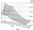
Фиг. 4 - диаграмма растворимости железа (Fe%) в жидкой смеси в зависимости от температуры (Т) и от содержания алюминия (Al%).FIG. 4 is a diagram of the solubility of iron (Fe%) in a liquid mixture as a function of temperature (T) and aluminum content (Al%).
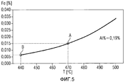
Фиг. 5 - часть диаграммы растворимости железа (Fe%) в жидкой смеси в зависимости от температуры (Т) при данном содержании алюминия (Al% = 0,19%).FIG. 5 is a part of the solubility diagram of iron (Fe%) in a liquid mixture depending on temperature (T) at a given aluminum content (Al% = 0.19%).
Фиг. 6 - диаграмма изменений мощности (РВ), добавляемой в жидкую смесь движущейся стальной полосой, и требуемой мощности (PZ) для обеспечения расплавления жидкой смеси в цинковальном баке (2).FIG. 6 is a diagram of changes in power (RV) added to the liquid mixture by a moving steel strip and the required power (PZ) to ensure the liquid mixture is melted in the zinc tank (2).
На фиг. 4 показано, что при данной температуре (в данном случае от Т=440°С до Т=480°С) предел растворимости железа (Fe%) в жидкой смеси Zn-Al повышается, когда содержание алюминия (Al%) понижается, а при данном содержании алюминия он повышается вместе с температурой. Таким образом, существуют два средства для управления пределом растворимости железа: изменять содержание алюминия или температуру жидкой смеси.In FIG. Figure 4 shows that at a given temperature (in this case, from T = 440 ° C to T = 480 ° C), the solubility limit of iron (Fe%) in the Zn-Al liquid mixture increases when the aluminum content (Al%) decreases, and at given aluminum content, it rises with temperature. Thus, there are two means to control the solubility limit of iron: change the aluminum content or the temperature of the liquid mixture.
На фиг. 5 показано изменение предела растворимости (Fe%) в зависимости от температуры (Т) при содержании алюминия (Al%) 0,19%. При температуре Т=470°C (точка А) цинковальной ванны (2) предел растворимости железа (Fe%) составляет примерно 0,015%. При температуре Т=440°С (точка В) ниже обычного значения предел растворимости железа (Fe%) составляет примерно 0,07%. Таким образом, в жидкой смеси, насыщенной или близкой к пределу насыщения при рабочей температуре 470°C, предел растворимости уменьшается в два раза при 440°С. При условии, что можно извлечь все дроссы, образовавшиеся из железа, выделившегося из раствора при этой температуре 440°С, содержание остающегося растворенным железа понижается до 0,07%. Нагрев из этого состояния до 470°С позволяет, таким образом, не осаждая дроссов, дополнительно растворить 0,08% железа из предназначенной для нанесения покрытия полосы.In FIG. Figure 5 shows the change in solubility limit (Fe%) as a function of temperature (T) with an aluminum content (Al%) of 0.19%. At a temperature of T = 470 ° C (point A) of the zinc bath (2), the solubility limit of iron (Fe%) is about 0.015%. At a temperature of T = 440 ° C (point B) below normal, the solubility limit of iron (Fe%) is about 0.07%. Thus, in a liquid mixture saturated or close to the saturation limit at an operating temperature of 470 ° C, the solubility limit is halved at 440 ° C. Provided that it is possible to extract all the drosses formed from the iron released from the solution at this
На фиг. 6 показаны изменения мощности (РВ), добавляемой в жидкую смесь движущейся стальной полосой, и мощности (PZ), необходимой для обеспечения плавления смеси, расходуемой в цинковальном баке (2). Эти мощности (РВ, PZ) ограничены двумя параметрами, характерными для установок непрерывного цинкования: мощностью нагрева печи (на фиг. 1 не показана, но находится перед цинковальным баком), с одной стороны, и максимальной скоростью, при которой обработка полосы остается эффективной. Например, эти пределы составляют примерно 100 тонн обработанной полосы в час для одной печи (после входа полосы в цинковальный бак) и немногим более 200 м/мин скорости полосы при обработке (на выходе полосы из цинковального бака). В представленном примере для полосы шириной (L), равной 1200 мм, и при температуре полосы 485°С кривая (показана пунктиром) мощности, называемой также мощностью «полосы» (РВ), непрерывно поднимается в зависимости от толщины (Е) полосы до горизонтального участка, соответствующего пределам нагрева печи. Кривая (сплошная линия) требуемой мощности (PZ) сначала ограничена максимальной скоростью движения полосы, которая, в свою очередь, ограничена максимальной скоростью обработки, затем постепенно понижается. Для толщины (Е) 1,2 мм полосы и толщины покрытия 15 мкм мощность (РВ), добавляемая полосой, ниже мощности (PZ), требуемой для плавления цинка (PZ>PB), и, следовательно, необходимо добавить разность мощности (ΔР) путем нагрева жидкой полосы во время циркуляции, в частности, пока она не вернется в цинковальный бак (2). Эта разность мощности в данном случае рассматривается как необходимое повышение мощности (ΔР>0). Разумеется, можно также предусмотреть понижение мощности (ΔР<0), и в этом случае необходимо изменить, по меньшей мере, один из параметров, влияющих на мощность (температура печи, скорость полосы и т.д.), чтобы уменьшить мощность, добавляемую в жидкую смесь, одновременно обеспечивая плавление смеси, расходуемой в цинковальном баке (2). В случае необходимости, с цинковальным баком можно соединить систему охлаждения.In FIG. Figure 6 shows the changes in power (RV) added to the liquid mixture by a moving steel strip and in the power (PZ) necessary to ensure melting of the mixture consumed in the zinc tank (2). These capacities (PB, PZ) are limited by two parameters characteristic of continuous galvanizing plants: the heating power of the furnace (not shown in FIG. 1, but located in front of the galvanizing tank), on the one hand, and the maximum speed at which the strip treatment remains effective. For example, these limits are approximately 100 tons of treated strip per hour for one furnace (after the strip enters the galvanizing tank) and a little more than 200 m / min of strip speed during processing (at the outlet of the strip from the galvanizing tank). In the presented example, for a strip with a width (L) of 1200 mm and at a strip temperature of 485 ° С, the curve (shown by a dotted line) of the power, also called the power of the “strip” (PB), continuously rises, depending on the thickness (E) of the strip, to horizontal area corresponding to the heating limits of the furnace. The curve (solid line) of the required power (PZ) is first limited by the maximum speed of the strip, which, in turn, is limited by the maximum processing speed, then gradually decreases. For a thickness (E) of 1.2 mm strip and a coating thickness of 15 μm, the power (RV) added by the strip is lower than the power (PZ) required for zinc melting (PZ> PB), and therefore it is necessary to add a power difference (ΔР) by heating the liquid strip during circulation, in particular, until it returns to the zinc tank (2). This power difference in this case is considered as a necessary increase in power (ΔP> 0). Of course, it is also possible to provide for a decrease in power (ΔP <0), in which case it is necessary to change at least one of the parameters affecting the power (furnace temperature, strip speed, etc.) in order to reduce the power added to liquid mixture, while ensuring the melting of the mixture consumed in the zinc tank (2). If necessary, a cooling system can be connected to the galvanizing tank.
На основании предыдущих фигур можно предложить способ в соответствии с настоящим изобретением, то есть способ цинкования погружением непрерывно движущейся полосы (1) стального проката, согласно которому полосу погружают в цинковальный бак (2), содержащий ванну (5) жидкой смеси наносимых на полосу металлов, таких как цинк (Zn) и алюминий (Al), непрерывно циркулирующей между упомянутым цинковальным баком и устройством (7) подготовки, в котором температуру жидкой смеси намеренно понижают, чтобы снизить порог растворимости железа, но поддерживают достаточно высокой, чтобы активировать в упомянутом устройстве подготовки плавление, по меньшей мере, одного слитка Zn-Al (8) в количестве, достаточном для компенсации жидкой смеси, расходуемой при нанесении на полосу, и неизбежных потерь (порядка 5%).Based on the previous figures, it is possible to propose a method in accordance with the present invention, that is, a method of galvanizing by immersion of a continuously moving strip (1) of rolled steel, according to which the strip is immersed in a zinc tank (2) containing a bath (5) of a liquid mixture applied to the strip of metals, such as zinc (Zn) and aluminum (Al), continuously circulating between said zinc tank and preparation device (7), in which the temperature of the liquid mixture is intentionally lowered to lower the solubility threshold of iron, but is maintained residually high to activate in said training device melting, at least one ingot Zn-Al (8) in an amount sufficient to compensate for the liquid mixture, when applied to a consumable strip, and unavoidable loss (about 5%).
Упомянутый способ содержит следующие этапы:Said method comprises the following steps:
- определяют первую мощность (РВ), обеспечиваемую стальной полосой, входящей при первой температуре (Т1) в ванну жидкой смеси цинковального бака, при этом упомянутую ванну стабилизируют при второй заранее определенной температуре (Т2), меньшей первой температуры (Т1),- determine the first power (RV) provided by the steel strip entering at the first temperature (T 1 ) into the bath of the liquid mixture of the galvanizing tank, while said bath is stabilized at a second predetermined temperature (T 2 ) less than the first temperature (T 1 ),
- определяют вторую мощность (PZ), необходимую для поддержания жидкой смеси при второй заранее определенной температуре (Т2), и эту вторую мощность сравнивают с первой мощностью (РВ), обеспечиваемой полосой,- determine the second power (PZ) necessary to maintain the liquid mixture at a second predetermined temperature (T 2 ), and this second power is compared with the first power (PB) provided by the strip,
- если первая мощность (РВ) выше второй мощности (PZ), для первой температуры (Т1) полосы применяют заданное значение понижения,- if the first power (RV) is higher than the second power (PZ), for the first temperature (T 1 ) of the strip, the set lowering value is applied,
- если первая мощность (РВ) ниже или равна второй мощности (PZ), определяют энергию, необходимую для непрерывного плавления слитка (8) в устройстве подготовки в количестве, необходимом для компенсации жидкой смеси, расходуемой при нанесении на полосу, а также любые сопутствующие потери,- if the first power (RV) is lower than or equal to the second power (PZ), determine the energy required for continuous melting of the ingot (8) in the preparation device in the amount necessary to compensate for the liquid mixture consumed when applied to the strip, as well as any associated losses ,
- корректируют расход циркуляции (Q2) жидкой смеси между цинковальным баком и устройством подготовки, чтобы обеспечить энергию, необходимую для непрерывного плавления слитка (8), поддерживая при этом температуру жидкой смеси в устройстве подготовки в значении третьей температуры (Т3), меньшей заранее определенной второй температуры (Т2),- adjust the flow rate (Q 2 ) of the liquid mixture between the zinc tank and the preparation device to provide the energy necessary for continuous melting of the ingot (8), while maintaining the temperature of the liquid mixture in the preparation device in the value of the third temperature (T 3 ), lower in advance a certain second temperature (T 2 ),
- корректируют четвертую температуру (Т4) жидкой смеси на выходе (9) устройства подготовки, чтобы обеспечить дополнительную мощность (ΔР=PZ-РВ), необходимую для термического равновесия между упомянутым выходом и входом (12) питания цинковального бака, при этом упомянутый вход питается от выхода (9).- adjust the fourth temperature (T 4 ) of the liquid mixture at the outlet (9) of the preparation device to provide additional power (ΔP = PZ-PB) necessary for thermal equilibrium between the said output and the input (12) of the galvanizing tank power supply, while the said input powered by output (9).
Таким образом, способ обеспечивает расход циркуляции жидкой смеси в непрерывном и последовательном режиме на пути потока между входом цинковального бака и выходом устройства подготовки, затем на идентичном пути обратного потока, отличного и противоположного пути потока. Этот расход циркуляции является также термически оптимизированным, так как циклично замыкается (поток, обратный поток) для каждого необходимого теплообмена, то есть его контролируют с достаточной точностью.Thus, the method provides the flow rate of the liquid mixture in a continuous and sequential mode on the flow path between the inlet of the galvanizing tank and the output of the preparation device, then on the identical return flow path, different and opposite flow paths. This circulation flow rate is also thermally optimized, as it cyclically closes (flow, return flow) for each necessary heat transfer, that is, it is controlled with sufficient accuracy.
Управление второй температурой (Т2) и искомым содержанием алюминия (Alv) позволяет контролировать порог растворимости (SFe T2) железа при второй температуре (Т2) в ванне (цинковальном баке) на таком уровне, чтобы, учитывая ожидаемую скорость растворения железа (QFe) в цинковальном баке, поддерживать общее содержание железа (Fe2) ниже порога растворимости (SFe T2) при второй температуре (Т2). Таким образом, поскольку цинковальный бак остается свободным от дроссов, покрытие имеет безупречное качество. Для этого путем регулирования второй температуры (Т2) и искомого содержания алюминия (Alv) порог растворимости (SFe T2) железа при второй температуре (Т2) в жидкой смеси цинковального бака контролируют на таком уровне, чтобы, учитывая ожидаемую скорость растворения железа (QFe) в цинковальном баке, поддерживать общее содержание железа (Fe2) ниже порога растворимости (SFe T2) при второй температуре (Т2).By controlling the second temperature (T 2 ) and the desired aluminum content (Al v ), it is possible to control the solubility threshold (SFe T 2 ) of iron at the second temperature (T 2 ) in the bath (zinc tank) at such a level that, taking into account the expected rate of dissolution of iron ( QFe) in the zinc tank, maintain the total iron (Fe 2 ) content below the solubility threshold (SFe T 2 ) at the second temperature (T 2 ). Thus, since the galvanizing tank remains free of drafts, the coating is of impeccable quality. To this end, by controlling the second temperature (T 2 ) and the desired aluminum content (Al v ), the solubility threshold (SFe T 2 ) of iron at the second temperature (T 2 ) in the liquid mixture of the zinc tank is controlled at such a level that, taking into account the expected rate of dissolution of iron (QFe) in the zinc tank, maintain the total iron (Fe 2 ) content below the solubility threshold (SFe T 2 ) at the second temperature (T 2 ).
Предпочтительно, чтобы непрерывное плавление слитков обеспечивалось при общем расходе плавления (Vm), по меньшей мере, двух слитков.Preferably, the continuous melting of the ingots is provided at a total melting rate (Vm) of at least two ingots.
Что касается плавления, как показано на фиг. 1 (или 2), предпочтительно в ванну жидкой смеси селективно и одновременно погружают переменное число (n) слитков. Предпочтительно каждый из слитков имеет разное содержание алюминия (Al1, Al2, …, Aln), и, по меньшей мере, один из слитков имеет содержание алюминия выше требуемого содержания (Alt) в устройстве подготовки (в частности, во второй зоне 72, содержащей очищенную смесь). Таким образом, сохранение или получение искомого значения содержания алюминия в зонах устройства подготовки можно осуществлять более гибко и более точно.With regard to melting, as shown in FIG. 1 (or 2), preferably a variable number (n) of ingots is selectively and simultaneously immersed in the bath of the liquid mixture. Preferably, each of the ingots has a different aluminum content (Al 1 , Al 2 , ..., Al n ), and at least one of the ingots has an aluminum content higher than the required content (Al t ) in the preparation device (in particular, in the
Для этого набора (n) слитков можно также индивидуально контролировать скорость погружения (V1, V2, …, Vn) каждого из (n) слитков, чтобы динамично корректировать содержание алюминия в устройстве подготовки по требуемому значению содержания (Alt), сохраняя при этом необходимую общую скорость (= расход) плавления (Vm).For this set of (n) ingots, it is also possible to individually control the rate of immersion (V 1 , V 2 , ..., V n ) of each of (n) ingots in order to dynamically adjust the aluminum content in the preparation device to the desired content value (Al t ), while maintaining the required total melting rate (= flow rate) (Vm).
В случае необходимости, можно активировать средство охлаждения жидкой смеси с второй температуры (Т2) до третьей температуры (Т3) в качестве вспомогательной системы в общем охлаждении, достигаемом при плавлении слитков. Такое дополнительное средство охлаждения позволяет добиться лучшей гибкости управления способом в соответствии с настоящим изобретением.If necessary, you can activate the means of cooling the liquid mixture from the second temperature (T 2 ) to the third temperature (T 3 ) as an auxiliary system in the overall cooling achieved by melting ingots. Such additional cooling means allows for better control flexibility in accordance with the present invention.
Предпочтительно можно осуществить разделение на отсеки между слитками и по их соответствующему содержанию алюминия, чтобы разделить между собой разные типы гроссов, при этом так называемые «поверхностные» гроссы с высоким содержанием алюминия предпочтительно образуются вблизи погруженных слитков с высоким содержанием алюминия, и так называемые «донные» гроссы с низким содержанием алюминия предпочтительно образуются вблизи погруженных слитков с низким содержанием алюминия. Это разделение на отсеки реализуют путем простого добавления перегородок между слитками на поверхности и на дне первой зоны (71).Advantageously, it is possible to divide into compartments between ingots and according to their respective aluminum content in order to separate different types of gross, the so-called “surface” gross high-aluminum grosses are preferably formed near submerged high-aluminum ingots, and the so-called “bottom” ones »Low-aluminum grasses are preferably formed near submerged low-aluminum ingots. This division into compartments is realized by simply adding partitions between ingots on the surface and at the bottom of the first zone (71).
Способ в соответствии с настоящим изобретением предусматривает регулирование необходимого расхода жидкого цинка, то есть расхода восстановления жидкой смеси, входящей в цинковальный бак, при содержании железа, равном порогу растворимости (SFe T3) железа при третьей температуре (Т3), чтобы ограничить повышение содержания растворенного железа намного ниже порога растворимости при второй температуре (Т2) в цинковальном баке. Это позволяет поддерживать количество растворенного железа, поступающего из полосы, в интервале между порогом растворимости (SFe T3) железа при третьей температуре (Т3) и порогом растворимости (SFe T2) железа при второй температуре (Т2).The method in accordance with the present invention provides for the regulation of the required flow rate of liquid zinc, that is, the recovery rate of the liquid mixture entering the zinc tank, with an iron content equal to the solubility threshold (SFe T 3 ) of iron at a third temperature (T 3 ) to limit the increase in the content dissolved iron is much lower than the solubility threshold at a second temperature (T 2 ) in a zinc tank. This allows you to maintain the amount of dissolved iron coming from the strip in the interval between the solubility threshold (SFe T 3 ) of iron at the third temperature (T 3 ) and the solubility threshold (SFe T 2 ) of iron at the second temperature (T 2 ).
Замкнутый цикл регулирования первой мощности (РВ), обеспечиваемой полосой, контролирует добавление или уменьшение мощности (ΔР), что приводит к равновесию, при котором первая мощность (РВ) равна сумме второй мощности (PZ) и добавления или уменьшения мощности (ΔР), то есть при котором PB=PZ+ΔP. Это достигается путем подачи команды на заданное понижение (или повышение) температуры полосы (Т1) на входе в цинковальный бак.The closed loop for controlling the first power (RV) provided by the strip controls the addition or decrease of power (ΔP), which leads to an equilibrium in which the first power (RV) is equal to the sum of the second power (PZ) and the addition or decrease of power (ΔP), then there is at which PB = PZ + ΔP. This is achieved by issuing a command for a given decrease (or increase) in the temperature of the strip (T 1 ) at the entrance to the galvanizing tank.
Способ предусматривает оборудование устройства подготовки дополнительными регулируемыми средствами отбора и удаления калорий, связанными с регулируемым средством индукционного нагрева, выполненными с возможностью модулирования третьей температуры (Т3) в зоне плавления слитков в температурном интервале +/-10°С значений, близких к значению температуры, задаваемому внешним средствами регулирования или управления.The method involves the equipment of the preparation device with additional adjustable calorie removal and removal means associated with an adjustable induction heating means, configured to modulate a third temperature (T 3 ) in the melting zone of the ingots in the temperature range +/- 10 ° C, values close to the temperature defined by external means of regulation or control.
С точки зрения термического процесса способ предполагает, что первая температура (Т1) стальной полосы при входе в цинковальный бак в идеале составляет от 450 до 550°С. Точно так же, вторая температура (Т2) жидкой смеси в цинковальном баке в идеале должна составлять от 450 до 520°С. Для максимальной эффективности способа разность температуры (ΔТ1) между стальной полосой и жидкой смесью в цинковальном баке поддерживают в пределах от 0 до 50°С. Таким образом, в идеале вторую температуру (Т2) жидкой смеси в цинковальном баке поддерживают с точностью от +/-1°С до +/-3°С в значении (Т1-ΔТ1), равном первой температуре (Т1) за вычетом разности температуры (ΔТ1) между стальной полосой и жидкой смесью. Наконец, понижение температуры (ΔТ2=Т2-Т3) между второй и третьей температурой жидкой смеси в устройстве подготовки поддерживают в значении не ниже 10°С. При значениях содержания цинка, алюминия и железа эти значения обеспечивают оптимальный замкнутый термический цикл в контуре (поток/обратный поток) циркуляции, применяемом для способа цинкования в соответствии с настоящим изобретением.From the point of view of the thermal process, the method assumes that the first temperature (T 1 ) of the steel strip at the entrance to the zinc tank is ideally between 450 and 550 ° C. Similarly, the second temperature (T 2 ) of the liquid mixture in the zinc tank should ideally be between 450 and 520 ° C. For maximum efficiency of the method, the temperature difference (ΔT 1 ) between the steel strip and the liquid mixture in the zinc tank is maintained in the range from 0 to 50 ° C. Thus, ideally, the second temperature (T 2 ) of the liquid mixture in the zinc tank is maintained with an accuracy of +/- 1 ° C to +/- 3 ° C in the value (T 1 -ΔT 1 ) equal to the first temperature (T 1 ) minus the temperature difference (ΔT 1 ) between the steel strip and the liquid mixture. Finally, a decrease in temperature (ΔT 2 = T 2 -T 3 ) between the second and third temperature of the liquid mixture in the preparation device is maintained at a value not lower than 10 ° C. With values of zinc, aluminum and iron, these values provide an optimal closed thermal cycle in the circuit (flow / return) of the circulation used for the galvanizing method in accordance with the present invention.
Способ предусматривает, чтобы расход циркуляции (Q2) жидкой смеси, поступающей из цинковального бака, постоянно составлял от 10 до 30-кратного значения количества смеси, наносимой на полосу за одну и ту же единицу времени.The method provides that the flow rate (Q 2 ) of the liquid mixture coming from the zinc tank is constantly from 10 to 30 times the amount of the mixture applied to the strip for the same unit of time.
Способ в соответствии с настоящим изобретением предусматривает также осуществление этапов измерения и контроля, обеспечивающих регулирование/поддерживание замкнутого термического цикла, контура циркуляции и искомых значений содержания алюминия, цинка и железа.The method in accordance with the present invention also provides for the implementation of the steps of measurement and control, providing regulation / maintenance of a closed thermal cycle, the circulation circuit and the desired values of the content of aluminum, zinc and iron.
В частности, значения температуры и концентрации алюминия в жидкой смеси измеряют, предпочтительно непрерывно, по меньшей мере, на пути потока от входа питания (12) в цинковальном баке до выхода (11) устройства подготовки. Эти значения являются определяющими для включения в диаграммы содержания алюминия или железа в зависимости от места нахождения жидкой смеси в замыкаемом контуре циркуляции.In particular, the temperature and the concentration of aluminum in the liquid mixture are measured, preferably continuously, at least in the flow path from the feed inlet (12) in the zinc tank to the outlet (11) of the preparation device. These values are decisive for inclusion in the diagrams of the content of aluminum or iron, depending on the location of the liquid mixture in the closed loop.
Предпочтительно непрерывно измеряют уровень жидкой смеси в устройстве подготовки и даже, в случае необходимости, в цинковальном баке. Это позволяет регулировать расход плавления слитков и контролировать количество металла, наносимого на полосу.Preferably, the level of the liquid mixture is continuously measured in the preparation device and even, if necessary, in the zinc tank. This allows you to adjust the consumption of melting ingots and control the amount of metal deposited on the strip.
На практике расход (например, содержание алюминия на единицу времени) и температуру жидкой смеси поддерживают в виде пар заранее определенных значений путем простого регулирования. Это позволяет, например, просто выводить на основании диаграммы (такой, как диаграммы, показанные на фиг. 1 и 2) и быстро получать идеальный порог растворимости (железа) для пары значений.In practice, the flow rate (for example, the aluminum content per unit time) and the temperature of the liquid mixture are maintained in pairs of predetermined values by simple regulation. This allows, for example, to simply derive from a diagram (such as the diagrams shown in FIGS. 1 and 2) and quickly obtain the ideal solubility threshold (iron) for a pair of values.
Способ включает функцию, при которой температуру полосы на выходе цинковальной печи, соединенном с входом в цинковальный бак, поддерживают в интервале регулируемых значений. Точно так же, скорость движения полосы поддерживают в интервале регулируемых значений. В идеале способ предусматривает измерение или оценку ширины и толщины полосы на входе в цинковальный бак, если они не были определены в качестве первичных входных параметров (Primary Data Input PDI) в системе управления установкой цинкования. Эти параметры необходимы для определения условий входа, в частности, в связи с мощностью, обеспечиваемой полосой в контуре циркуляции, управляемом способом в соответствии с настоящим изобретением.The method includes a function in which the temperature of the strip at the outlet of the galvanizing furnace, connected to the inlet of the galvanizing tank, is maintained in the range of adjustable values. Similarly, the speed of the strip is maintained in the range of adjustable values. Ideally, the method involves measuring or evaluating the width and thickness of the strip at the entrance to the galvanizing tank, if they were not defined as primary input parameters (Primary Data Input PDI) in the control system of the galvanizing plant. These parameters are necessary to determine the entry conditions, in particular in connection with the power provided by the strip in the circulation loop, controlled by the method in accordance with the present invention.
Чтобы иметь возможность модулировать скорость плавления каждого из слитков, введение и удержание слитков в зоне плавления устройства подготовки осуществляют динамично и селективно.In order to be able to modulate the melting rate of each of the ingots, the introduction and retention of the ingots in the melting zone of the preparation device is carried out dynamically and selectively.
Таким образом, способ в соответствии с настоящим изобретением осуществляют в зависимости от динамических параметров измерения и регулирования, связанных с полосой, с цинковальным баком и с устройством подготовки. В идеале этими параметрами управляют централизованно и автономно согласно аналитической модели прогнозируемого управления в режиме реального времени, которая в факультативном варианте автоматически обновляется. В этой связи можно также применять режим внешнего управления (например, путем простого ввода внешних команд в аналитическую модель, управляющую упомянутым процессом), чтобы, например, оператор мог корректировать содержание алюминия, температуру полосы и т.д. Аналитическую модель регулирования процесса тоже обновляют в соответствии с таким внешним управлением.Thus, the method in accordance with the present invention is carried out depending on the dynamic measurement and regulation parameters associated with the strip, with the galvanizing tank and with the preparation device. Ideally, these parameters are controlled centrally and autonomously according to the analytical model of predicted control in real time, which in the optional version is automatically updated. In this regard, you can also apply the external control mode (for example, by simply entering external commands into the analytical model that controls the process), so that, for example, the operator can adjust the aluminum content, strip temperature, etc. The analytical model of process control is also updated in accordance with such external management.
Так же, как и в случае параметров, получаемых из цинковальной печи на входе цинковального бака, для управления способом в соответствии с настоящим изобретением можно получать параметры измерения и регулирования в результате процесса сушки полосы, выходящей из цинковального бака. Это позволяет лучше калибровать предварительные регулировочные значения, связанные с толщиной покрытия и с требуемыми значениями содержания наносимого металла.As in the case of the parameters obtained from the galvanizing furnace at the inlet of the galvanizing tank, to control the method in accordance with the present invention, it is possible to obtain measurement and control parameters as a result of the drying process of the strip exiting the galvanizing tank. This makes it possible to better calibrate the preliminary adjustment values associated with the coating thickness and with the required values of the applied metal content.
В этом смысле преимущества изобретения раскрыты в зависимых пунктах формулы изобретения.In this sense, the advantages of the invention are disclosed in the dependent claims.
Примеры реализации и применения способа проиллюстрированы на предыдущих фигурах и на следующих фигурах.Examples of the implementation and application of the method are illustrated in the previous figures and in the following figures.
Фиг. 7 - логическая схема определения значений мощности.FIG. 7 is a logic diagram for determining power values.
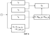
Фиг. 8 - логическая схема определения расхода циркуляции жидкой смеси.FIG. 8 is a logic diagram for determining the flow rate of a liquid mixture.
Фиг. 9 - логическая схема определения содержания алюминия.FIG. 9 is a logic diagram for determining aluminum content.
Фиг. 10 - логическая схема определения скорости плавления слитков.FIG. 10 is a logical diagram for determining the melting rate of ingots.
Фиг. 11 - логическая схема проверки теоретического содержания растворенного железа в жидкой смеси.FIG. 11 is a flowchart for verifying the theoretical content of dissolved iron in a liquid mixture.
На фиг. 7 показана логическая схема определения значений мощности полосы (РВ) и требуемой мощности (PZ) для осуществления способа в соответствии с настоящим изобретением. На основании данных, касающихся продукта (DAT_BAND) и условий управления (DAT_DRIV) установкой (см. фиг. 1, 2 и 3), то есть:In FIG. 7 shows a logic diagram for determining values of band power (RV) and required power (PZ) for implementing the method in accordance with the present invention. Based on the data regarding the product (DAT_BAND) and the control conditions (DAT_DRIV) of the installation (see Figs. 1, 2 and 3), that is:
- ширины (L) и толщины (Е) непрерывно движущейся полосы,- the width (L) and thickness (E) of the continuously moving strip,
- толщины цинка (EZ), наносимого на обе стороны полосы, и требуемой скорости (V) полосы,- the thickness of the zinc (EZ) applied on both sides of the strip, and the required speed (V) of the strip,
вычисляют массовый расход (QBm) и расход на единицу поверхности (QBs) полосы, а также общий расход потребляемого цинка (Q1), в том числе неизбежные потери.calculate mass flow rate (QBm) and flow rate per unit surface area (QBs) of the strip, as well as the total consumption of zinc consumed (Q 1 ), including unavoidable losses.
На оснований этих значений расхода, первой температуры (Т1) полосы на выходе цинковальной печи перед цинковальным баком и второй температуры (Т2) в цинковальном баке вычисляют мощность полосы (РВ) и требуемую мощность (PZ).Based on these flow values, the first temperature (T 1 ) of the strip at the outlet of the galvanizing furnace in front of the galvanizing tank and the second temperature (T 2 ) in the galvanizing tank, the strip power (PB) and the required power (PZ) are calculated.
Если, как в случае показанном на фиг. 6, требуемая мощность превышает мощность полосы (PZ>PB, случай “Y”), производят ряд вычислений (см. фиг. 8) в виде:If, as in the case shown in FIG. 6, the required power exceeds the power of the strip (PZ> PB, case “Y”), a number of calculations are performed (see Fig. 8) in the form:
ΔP=PZ-PB (этап «1»).ΔP = PZ-PB (step "1").
С другой стороны, требуемая мощность может быть меньше мощности полосы (PZ<PB, случай “N”). В этом случае способ в соответствии с настоящим изобретением предусматривает заданное значение (ORD1) охлаждения (ΔТ) для первой температуры полосы (Т1) путем понижения температуры на выходе цинковальной печи. После этого этапа температура жидкой смеси в цинковальном баке должна вернуться к своему значению (Т2) с учетом того, что температура полосы (Т1) на входе в цинковальный бак равна второй температуре (Т2), увеличенной на определенное значение, в данном случае охлаждение (ΔТ) по абсолютной величине, то есть On the other hand, the required power may be less than the band power (PZ <PB, case “N”). In this case, the method in accordance with the present invention provides a predetermined cooling value (ORD1) (ΔT) for the first strip temperature (T 1 ) by lowering the outlet temperature of the galvanizing furnace. After this stage, the temperature of the liquid mixture in the galvanizing tank should return to its value (T 2 ), taking into account the fact that the temperature of the strip (T 1 ) at the entrance to the galvanizing tank is equal to the second temperature (T 2 ), increased by a certain value, in this case cooling (ΔТ) in absolute value, i.e.
Т1=Т2+ΔТ.T 1 = T 2 + ΔT.
На фиг. 8 показана логическая схема определения расхода циркуляции жидкой смеси, связанного с результатом этапа «1», показанного на фиг. 1 и представленного также как логическая исходная точка настоящей схемы. На основании искомой третьей температуры (Т3) в зоне плавления (71) слитков устройства подготовки, исходной температуры (TL) слитков, причем эти слитки можно, в случае необходимости, нагреть перед введением в жидкую смесь, и расхода (Q1) потребляемого цинка определяют энергию (W=Wfus_Zn) плавления упомянутых слитков цинка. Эта энергия представляет собой также энергию (Winc_Zn), обеспечиваемую жидким цинком, поступающим из цинковального бака.In FIG. 8 is a flowchart for determining a flow rate of a liquid mixture associated with the result of step “1” shown in FIG. 1 and also represented as the logical starting point of the present scheme. Based on the desired third temperature (T 3 ) in the melting zone (71) of the ingots of the preparation device, the initial temperature (T L ) of the ingots, these ingots can, if necessary, be heated before being introduced into the liquid mixture, and the flow rate (Q 1 ) consumed zinc determine the energy (W = W fus_Zn ) of the melting of said zinc ingots. This energy is also the energy (W inc_Zn ) provided by liquid zinc coming from the zinc tank.
С учетом второй температуры (Т2) жидкой смеси, поступающей из цинковального бака, и предварительно вычисленной энергии (W) определяют расход (Q2) жидкой смеси, поступающей из цинковального бака и необходимой для обеспечения непрерывного плавления слитков. Этот расход (Q2) указывает также на расход циркуляции жидкой смеси между цинковальным баком и устройством подготовки.Taking into account the second temperature (T 2 ) of the liquid mixture coming from the zinc tank and the pre-calculated energy (W), the flow rate (Q 2 ) of the liquid mixture coming from the zinc tank and necessary to ensure continuous melting of the ingots is determined. This flow rate (Q 2 ) also indicates the flow rate of the liquid mixture between the zinc tank and the preparation device.
На фиг. 9 показана логическая схема определения содержания алюминия (Alt) жидкой смеси в результате плавления слитков в устройстве подготовки (бак очистки 72). Действительно, образование определенных соединений Fe-Al, которые, с одной стороны, формируют комбинированный слой, наносимый на полосу, и которые, с другой стороны, присутствуют в гроссах, приводит к расходу алюминия, соответственно (QAlc) и (QAld), который добавляется к количеству, обычно наносимому вместе с цинком на полосу. Этот дополнительный расход необходимо компенсировать содержанием алюминия (Alt) в баке очистки (72), слегка превышающим искомое содержание алюминия (Alv) в цинковальном баке. Значения расхода (QAlc) и (QAld) вычисляют на основании массового расхода (QBm) полосы. Их включают также в схему вычисления четвертой температуры (Т4) жидкой смеси, возвращающейся в цинковальный бак, в зависимости от третьей температуры (Т3), получаемой после плавления слитков, и дополнительной мощности (ΔР), необходимой для доведения температуры жидкой смеси до второй температуры (Т2) в цинковальном баке. После этого значение содержания алюминия (Alt) учитывают с точки зрения расхода, чтобы перейти к этапу «2», представленному на следующей фигуре.In FIG. 9 shows a logic diagram for determining the aluminum content (Al t ) of a liquid mixture as a result of melting ingots in a preparation device (treatment tank 72). Indeed, the formation of certain Fe-Al compounds, which, on the one hand, form a combined layer deposited on the strip, and which, on the other hand, are present in grosses, leads to the consumption of aluminum, respectively (QAl c ) and (QAl d ), which is added to the amount usually applied with zinc to the strip. This additional flow rate must be compensated by the aluminum content (Al t ) in the cleaning tank (72), slightly exceeding the desired aluminum content (Al v ) in the zinc tank. The flow rates (QAl c ) and (QAl d ) are calculated based on the mass flow rate (QBm) of the strip. They are also included in the calculation scheme of the fourth temperature (T 4 ) of the liquid mixture returning to the zinc tank, depending on the third temperature (T 3 ) obtained after the ingots are melted, and the additional power (ΔР) necessary to bring the temperature of the liquid mixture to the second temperature (T 2 ) in the galvanizing tank. After that, the value of the aluminum content (Al t ) is taken into account from the point of view of flow in order to proceed to step "2", presented in the following figure.
На фиг. 10 показана логическая диаграмма определения скорости (=расход) плавления слитков в устройстве подготовки. В зависимости от количества потерь алюминия (QAlc) в комбинированном слое и потерь алюминия (QAld) в гроссах, которые меняются, в частности, в зависимости от ширины обрабатываемой полосы, необходимо иметь возможность адаптировать содержание алюминия (Alt), получаемого в результате плавления слитков, чтобы поддерживать необходимое значение содержания алюминия (Alv) в цинковальном баке. Для этого предпочтительно в жидкую смесь устройства подготовки одновременно и селективно погружают, по меньшей мере, два слитка с разным содержанием алюминия, по меньшей мере, один из которых имеет содержание алюминия выше, чем содержание алюминия (Alt) во второй зоне (72) устройства подготовки. Набор из (n) слитков погружают в жидкий металл при общей скорости (=расход) плавления (Vm), соответствующей вычисленному общему расходу (Q1) потребляемого цинка. Каждый из (n) слитков с содержанием алюминия (Al1, Al2, …, Aln) погружают селективно и соответственно динамике (продолжительность погружения), переменно адаптируемой для каждого слитка с учетом вычисленной скорости плавления (V1, V2, …, Vn), чтобы обеспечить результирующее содержание алюминия (Alt), связанное с общей скоростью плавления (Vm), и чтобы требуемое содержание алюминия (Alt), связанное с предусмотренным расходом алюминия по значению, полученному на этапе «2», представленном на предыдущей фиг. 9, обеспечивалось содержанием алюминия (Alt), получаемым в результате плавления слитков.In FIG. 10 is a logical diagram for determining the rate (= flow rate) of melting ingots in a preparation device. Depending on the amount of aluminum loss (QAl c ) in the combined layer and aluminum loss (QAl d ) in the gross, which vary, in particular, depending on the width of the processed strip, it is necessary to be able to adapt the aluminum content (Al t ) resulting from melting ingots in order to maintain the required value of aluminum (Al v ) in the zinc tank. For this, it is preferable that at least two ingots with different aluminum contents are simultaneously and selectively immersed in the liquid mixture of the preparation device, at least one of which has an aluminum content higher than the aluminum content (Al t ) in the second zone (72) of the device training. A set of (n) ingots is immersed in a liquid metal at a total melting rate (= flow rate) (V m ) corresponding to the calculated total zinc consumption (Q 1 ). Each of (n) ingots with aluminum content (Al 1 , Al 2 , ..., Al n ) is immersed selectively and correspondingly to dynamics (immersion time), which is variable for each ingot taking into account the calculated melting rate (V 1 , V 2 , ..., V n ) in order to ensure the resulting aluminum content (Al t ) associated with the total melting rate (V m ), and that the required aluminum content (Al t ) associated with the intended consumption of aluminum from the value obtained in step "2", presented in the previous FIG. 9 was provided by the aluminum content (Al t ) obtained by melting the ingots.
На фиг. 11 показана логическая диаграмма проверки теоретического содержания железа (SFe), растворенного в жидкой смеси, на основании описанного выше этапа «1» (см. фиг. 6, 7, 8). Содержание железа (Fe1) в жидкой смеси, входящей в цинковальный бак, фиксируется порогом растворимости (SFe T3) железа при третьей температуре (Т3) осаждения гроссов (Fe1=SFe T3) (см. также фиг.1). В зависимости от данных, таких как первая температура (Т1) полосы на входе в цинковальный бак, вторая температура (Т2) жидкой смеси в упомянутом цинковальном баке, расход на единицу поверхности полосы (QBs) и содержание алюминия (Alv) в жидкой смеси на входе в устройство подготовки, способ включает вычисление, с одной стороны, расхода растворения железа (QFe), получаемого с двух сторон движущейся полосы, и, с другой стороны, порога растворимости (SFe T2) железа в жидкой смеси при второй температуре (Т2). Этот расход растворения, добавленный к содержанию железа (Fe1) на входе цинковального бака, позволяет вычислить содержание железа в жидкой смеси (Fe2)In FIG. 11 is a logic diagram for checking the theoretical content of iron (SFe) dissolved in a liquid mixture based on the above described step “1” (see FIGS. 6, 7, 8). The iron content (Fe 1 ) in the liquid mixture entering the zinc tank is fixed by the solubility threshold (SFe T 3 ) of iron at the third temperature (T 3 ) of deposition of gross (Fe 1 = SFe T 3 ) (see also FIG. 1). Depending on the data, such as the first temperature (T 1 ) of the strip at the inlet of the zinc tank, the second temperature (T 2 ) of the liquid mixture in said zinc tank, the flow rate per unit surface of the strip (QBs) and the aluminum content (Al v ) in the liquid mixture at the entrance to the preparation device, the method includes calculating, on the one hand, the rate of dissolution of iron (QFe) obtained from both sides of the moving strip, and, on the other hand, the solubility threshold (SFe T 2 ) of iron in the liquid mixture at the second temperature ( T 2 ). This dissolution rate added to the iron (Fe 1 ) content at the inlet of the galvanizing tank allows the iron content in the liquid mixture (Fe 2 ) to be calculated.
Fe2=(QFe · SFe)+Fe1, Fe 2 = (QFe · SFe) + Fe 1,
куда вводят коэффициент безопасности (SFe). На поверхности полосы устанавливается большой градиент концентрации железа, способствующий развитию комбинированного слоя Fe2Al5Znx. Содержание железа (Fe2) в жидкой смеси в цинковальном баке является в этом случае содержанием железа в конце упомянутого градиента и может считаться общим содержанием железа в ванне жидкой смеси. Если порог растворимости (SFe T2) железа в жидкой смеси при второй температуре (Т2) превышает реальное содержание железа жидкой смеси (Fe2) в цинковальном баке (см. случай «SFe T2>Fe2»), то подтверждают различные полученные параметры регулирования способа (см. случай «VAL_PA»). В противном случае эти параметры необходимо изменить (см. случай «MOD_PA»), чтобы повысить (случай «UP(SFe T2)») порог растворимости (SFe T2) железа в жидкой смеси при второй температуре (Т2) и/или снизить (случай «DOWN(QFe)») расход растворения железа (QFe). Увеличение упомянутого порога растворимости (SFe T2) получают путем повышения второй температуры (Т2) и/или снижения содержания алюминия (Alv) в цинковальном баке. Уменьшение расхода растворения железа (QFe) получают путем понижения первой температуры (Т1) и/или второй температуры (Т2) и/или расхода на единицу поверхности полосы (QBs) и/или путем повышения содержания алюминия (Alv) в цинковальном баке. Практически предпочтительно воздействуют на первую температуру (Т1) полосы и/или на скорость ее движения (V).where the safety factor (S Fe ) is introduced. A large gradient of iron concentration is established on the surface of the strip, which contributes to the development of the combined Fe 2 Al 5 Zn x layer. The iron content (Fe 2 ) in the liquid mixture in the zinc tank is in this case the iron content at the end of the gradient and can be considered the total iron content in the bath of the liquid mixture. If the solubility threshold (SFe T 2 ) of iron in the liquid mixture at the second temperature (T 2 ) exceeds the actual iron content of the liquid mixture (Fe 2 ) in the zinc tank (see the case "SFe T 2 > Fe 2 "), then various obtained method control parameters (see case “VAL_PA"). Otherwise, these parameters must be changed (see the “MOD_PA” case) to increase (the case “UP (SFe T 2 )”) the solubility threshold (SFe T 2 ) of iron in the liquid mixture at the second temperature (T 2 ) and / or reduce (the case of "DOWN (QFe)") the rate of dissolution of iron (QFe). An increase in said solubility threshold (SFe T 2 ) is obtained by increasing the second temperature (T 2 ) and / or lowering the aluminum content (Al v ) in the zinc tank. A decrease in the dissolution rate of iron (QFe) is obtained by lowering the first temperature (T 1 ) and / or the second temperature (T 2 ) and / or the flow rate per unit surface of the strip (QBs) and / or by increasing the aluminum content (Al v ) in the zinc tank . It is almost preferable to act on the first temperature (T 1 ) of the strip and / or on its speed (V).
Список основных обозначенийList of basic symbols
1 непрерывно движущаяся полоса1 continuously moving strip
2, 13 цинковальный бак2, 13 galvanizing tank
7 устройство подготовки7 preparation device
71, 72 первая и вторая зоны устройства подготовки71, 72 first and second zones of the preparation device
8 слиток (слитки)8 ingot (ingots)
А предельная точка растворимости железа при 470°С при содержании алюминия 0,19%And the limit point of solubility of iron at 470 ° C with an aluminum content of 0.19%
Al алюминийAl aluminum
Al1,…,Aln содержание алюминия слитков 1-nAl 1 , ..., Al n the aluminum content of the ingots 1-n
Alc расход алюминия в комбинированном слоеAl c consumption of aluminum in the combined layer
Ald расход алюминия в гроссахAl d gross aluminum consumption
Al1 повышение содержания алюминия жидкой смеси, требуемого в устройстве подготовкиAl 1 increase in the aluminum content of the liquid mixture required in the preparation device
Alm максимальное (виртуальное) содержание алюминия жидкой смеси в устройстве подготовки (первая зона 71)Al m maximum (virtual) aluminum content of the liquid mixture in the preparation device (first zone 71)
Alt содержание алюминия в жидкой смеси, получаемого из слитков, расплавленных в устройстве подготовки (то есть во второй зоне 72)Al t the aluminum content in the liquid mixture obtained from ingots melted in the preparation device (i.e. in the second zone 72)
Alv искомое содержание алюминия в жидкой смеси на выходе цинковального бакаAl v the desired aluminum content in the liquid mixture at the outlet of the galvanizing tank
В предельная точка растворимости железа при 440°С при содержании алюминия 0,19%At the limit point of solubility of iron at 440 ° C with an aluminum content of 0.19%
DAT_BAND данные полосыDAT_BAND strip data
DAT_DRIV данные управленияDAT_DRIV control data
DOWN(x) уменьшить переменную хDOWN (x) reduce the variable x
Dross штейн, дроссDross matte, dross
ΔР добавление (ΔР>0) или уменьшение (ΔР<0) мощностиΔР adding (ΔР> 0) or decreasing (ΔР <0) power
ΔT положительное (ΔT>0) или отрицательное (ΔT<0) изменение температуры, соответствующее добавлению или уменьшению энергииΔT positive (ΔT> 0) or negative (ΔT <0) temperature change corresponding to the addition or decrease of energy
Е толщина полосыE strip thickness
EZ толщина цинкаEZ Zinc Thickness
Fe железоFe iron
Fe1 содержание железа жидкой смеси на входе цинковального бакаFe 1 iron content of the liquid mixture at the inlet of the galvanizing tank
Fe2 максимальное содержание железа жидкой смеси в цинковальном бакеFe 2 maximum iron content of the liquid mixture in the zinc tank
L ширина полосыL strip width
MOD_PA изменение выбранных параметровMOD_PA change selected parameters
N нетN no
ORD1 заданное значениеORD1 setpoint
PZ мощность, необходимая для поддержания цинка при Т2 PZ power required to maintain zinc at T 2
PB мощность, обеспечиваемая полосойPB power provided by the strip
Q1 =Q1_fus_Zn расход плавления цинковых слитковQ 1 = Q 1_fus_Zn the consumption of melting zinc ingots
=Q1_cons_Zn общий расход потребляемого цинка-алюминия= Q 1_cons_Zn total consumption of zinc-aluminum consumed
Q2 необходимый расход жидкого цинка на выходе цинковального бакаQ 2 the required flow rate of liquid zinc at the outlet of the galvanizing tank
QAlc интенсивность потери Al в комбинированном слоеQAl c Al loss rate in the composite layer
QAld интенсивность потери Al в гроссахQAl d Al loss rate in gross
QBm массовый расход полосыQBm mass flow strip
QBs расход на единицу поверхности полосыQBs flow rate per unit strip surface
QFe расход растворения железа в жидкой смесиQFe flow rate of dissolution of iron in a liquid mixture
SFe порог растворимости/насыщения железа в жидкой смесиSFe solubility / saturation threshold of iron in a liquid mixture
SFe T2 SFe для жидкой смеси при температуре Т2 SFe T 2 SFe for liquid mixture at temperature T 2
SFe T3 SFe для жидкой смеси при температуре Т3 SFe T 3 SFe for liquid mixture at temperature T 3
SFe T4 SFe для жидкой смеси при температуре Т4 SFe T 4 SFe for liquid mixture at temperature T 4
T1 1-я температура полосы на входе цинковального бакаT 1 1st strip temperature at the inlet of the galvanizing tank
T1_mes измеренная Т1 T 1_mes measured T 1
T2 2-я температура жидкой смеси в цинковальном бакеT 2 2nd temperature of the liquid mixture in the zinc tank
T3 3-я температура устройства (ванны) подготовкиT 3 3rd temperature of the preparation device (bath)
Т4 4-я температура на выходе бака очисткиT 4 4th temperature at the outlet of the cleaning tank
TL первоначальная температура слитков до погружения в зону плавленияT L initial temperature of the ingots before immersion in the melting zone
UP(x) увеличить переменную (х)UP (x) increment variable (x)
V скорость движения полосыV lane speed
Vm общий расход плавления погруженных слитковVm total melting rate of submerged ingots
Vmax максимальная скорость движения полосыV max maximum lane speed
V1,…, Vn значения расхода плавления слитков 1-nV 1 , ..., V n the values of the flow rate of melting ingots 1-n
VAL_PA подтверждение выбранных параметровVAL_PA confirmation of selected parameters
W =Wfus_Zn энергия плавления слитков цинкаW = W fus_Zn melting energy of zinc ingots
=Winc_Zn энергия, добавляемая жидким цинком, поступающим из цинковального бака= W inc_Zn is the energy added by liquid zinc coming from a galvanizing tank
Y даY yes
Zn цинкZn Zinc
Claims (27)
определяют первую мощность (РВ), обеспечиваемую стальной полосой, входящей при первой температуре (T1) в ванну (5) жидкой смеси цинковального бака, при этом упомянутую ванну стабилизируют при второй заранее определенной температуре (Т2), меньшей первой температуры (T1),
определяют вторую мощность (PZ), необходимую для поддержания жидкой смеси металлов при второй заранее определенной температуре (Т2), и эту вторую мощность сравнивают с первой мощностью (РВ), обеспечиваемой полосой,
если первая мощность (РВ) выше второй мощности (PZ), для первой температуры (T1) полосы применяют заданное значение понижения,
если первая мощность (РВ) ниже или равна второй мощности (PZ), определяют энергию, необходимую для непрерывного плавления в устройстве подготовки слитка (8) в количестве, необходимом для компенсации жидкой смеси металлов, расходуемой при нанесении на полосу,
корректируют расход циркуляции (Q2) жидкой смеси металлов между цинковальным баком и устройством подготовки, чтобы обеспечить энергию, необходимую для непрерывного плавления слитка (8), поддерживая при этом температуру жидкой смеси металлов в устройстве подготовки в значении заранее определенной третьей температуры (Т3), меньшей заранее определенной второй температуры (T2),
корректируют четвертую температуру (Т4) жидкой смеси металлов на выходе (9) устройства подготовки, чтобы обеспечить дополнительную мощность (ΔP=PZ-PB), необходимую для термического равновесия между упомянутым выходом и входом (12) питания цинковального бака, при этом упомянутый вход питается от выхода (9).1. A method of galvanizing by immersion of a continuously moving strip (1) of rolled steel, comprising immersing the strip in a zinc tank (2) containing a bath (5) of a liquid mixture of metals deposited onto the strip, such as zinc and aluminum, continuously circulating between the said zinc tank and the device (7) a preparation in which the temperature of the liquid metal mixture is intentionally lowered to lower the solubility threshold of iron, and kept high enough to activate at least one Zn-Al ingot (8) in an amount sufficient to compensate for the liquid metal mixture consumed when applied to the strip, while
determine the first power (RV) provided by the steel strip entering at the first temperature (T 1 ) into the bath (5) of the liquid mixture of the zinc tank, while said bath is stabilized at a second predetermined temperature (T 2 ) less than the first temperature (T 1 ),
determine the second power (PZ) necessary to maintain the liquid metal mixture at a second predetermined temperature (T 2 ), and this second power is compared with the first power (PB) provided by the strip,
if the first power (RV) is higher than the second power (PZ), a set lowering value is applied to the first temperature (T 1 ) of the strip,
if the first power (RV) is lower than or equal to the second power (PZ), determine the energy required for continuous melting in the preparation device of the ingot (8) in the amount necessary to compensate for the liquid metal mixture consumed when applied to the strip,
adjust the flow rate (Q 2 ) of the liquid metal mixture between the zinc tank and the preparation device to provide the energy necessary for continuous melting of the ingot (8), while maintaining the temperature of the liquid metal mixture in the preparation device at a predetermined third temperature (T 3 ) less than a predetermined second temperature (T 2 ),
adjust the fourth temperature (T 4 ) of the liquid metal mixture at the outlet (9) of the preparation device to provide the additional power (ΔP = PZ-PB) necessary for thermal equilibrium between the said output and the input (12) of the galvanizing tank supply, while the said input powered by output (9).
Priority Applications (1)
| Application Number | Priority Date | Filing Date | Title |
|---|---|---|---|
| RU2010137276/02A RU2463379C2 (en) | 2008-02-08 | 2008-02-08 | Method of galvanisation by submersion of steel strip |
Applications Claiming Priority (1)
| Application Number | Priority Date | Filing Date | Title |
|---|---|---|---|
| RU2010137276/02A RU2463379C2 (en) | 2008-02-08 | 2008-02-08 | Method of galvanisation by submersion of steel strip |
Publications (2)
| Publication Number | Publication Date |
|---|---|
| RU2010137276A RU2010137276A (en) | 2012-03-20 |
| RU2463379C2 true RU2463379C2 (en) | 2012-10-10 |
Family
ID=46029639
Family Applications (1)
| Application Number | Title | Priority Date | Filing Date |
|---|---|---|---|
| RU2010137276/02A RU2463379C2 (en) | 2008-02-08 | 2008-02-08 | Method of galvanisation by submersion of steel strip |
Country Status (1)
| Country | Link |
|---|---|
| RU (1) | RU2463379C2 (en) |
Cited By (1)
| Publication number | Priority date | Publication date | Assignee | Title |
|---|---|---|---|---|
| RU2628182C2 (en) * | 2013-02-06 | 2017-08-15 | Арселормиттал | Treatment method for moving ferroalloy sheet and continuous production line for its implementation |
Citations (3)
| Publication number | Priority date | Publication date | Assignee | Title |
|---|---|---|---|---|
| EP0429351A1 (en) * | 1989-11-21 | 1991-05-29 | Sollac | Method and apparatus for removing impurities from a molten metal bath for hot dipping a steel strip |
| EP1070765A1 (en) * | 1998-04-01 | 2001-01-24 | Nkk Corporation | Hot dip zincing method and device therefor |
| RU2209846C2 (en) * | 2001-04-26 | 2003-08-10 | Открытое акционерное общество "Новолипецкий металлургический комбинат" | Method for continuous zincing of strip |
-
2008
- 2008-02-08 RU RU2010137276/02A patent/RU2463379C2/en active
Patent Citations (3)
| Publication number | Priority date | Publication date | Assignee | Title |
|---|---|---|---|---|
| EP0429351A1 (en) * | 1989-11-21 | 1991-05-29 | Sollac | Method and apparatus for removing impurities from a molten metal bath for hot dipping a steel strip |
| EP1070765A1 (en) * | 1998-04-01 | 2001-01-24 | Nkk Corporation | Hot dip zincing method and device therefor |
| RU2209846C2 (en) * | 2001-04-26 | 2003-08-10 | Открытое акционерное общество "Новолипецкий металлургический комбинат" | Method for continuous zincing of strip |
Cited By (2)
| Publication number | Priority date | Publication date | Assignee | Title |
|---|---|---|---|---|
| RU2628182C2 (en) * | 2013-02-06 | 2017-08-15 | Арселормиттал | Treatment method for moving ferroalloy sheet and continuous production line for its implementation |
| US10590501B2 (en) | 2013-02-06 | 2020-03-17 | Arcelormittal | Method of treatment of a running ferrous alloy sheet and treatment line for its implementation |
Also Published As
| Publication number | Publication date |
|---|---|
| RU2010137276A (en) | 2012-03-20 |
Similar Documents
| Publication | Publication Date | Title |
|---|---|---|
| US8464654B2 (en) | Hot-dip galvanizing installation for steel strip | |
| US9238859B2 (en) | Method for the hardened galvanization of a steel strip | |
| KR101562085B1 (en) | Method and device for controlling the introduction of several metals into a cavity designed to melt said metals | |
| US9181612B2 (en) | Manufacturing equipment for galvannealed steel sheet, and manufacturing method of galvannealed steel sheet | |
| RU2463379C2 (en) | Method of galvanisation by submersion of steel strip | |
| US9487852B2 (en) | Manufacturing equipment for galvanized steel sheet, and manufacturing method of galvanized steel sheet | |
| RU2463378C2 (en) | Plant for galvanisation by submersion of steel strip | |
| JPH03188250A (en) | Molten metal dipping vessel used for continuous hot-dipping | |
| JP5125198B2 (en) | Method for hot metal plating of steel sheet using continuous hot metal plating equipment | |
| JPH04232237A (en) | Method for assuming reducing quantity of component in plating bath and control learning method |
Legal Events
| Date | Code | Title | Description |
|---|---|---|---|
| PD4A | Correction of name of patent owner |