RU2459675C2 - Method of producing fine-powder mineral products - Google Patents
Method of producing fine-powder mineral products Download PDFInfo
- Publication number
- RU2459675C2 RU2459675C2 RU2009122189/03A RU2009122189A RU2459675C2 RU 2459675 C2 RU2459675 C2 RU 2459675C2 RU 2009122189/03 A RU2009122189/03 A RU 2009122189/03A RU 2009122189 A RU2009122189 A RU 2009122189A RU 2459675 C2 RU2459675 C2 RU 2459675C2
- Authority
- RU
- Russia
- Prior art keywords
- air
- water
- separator
- separation
- temperature
- Prior art date
Links
Images


Classifications
-
- B—PERFORMING OPERATIONS; TRANSPORTING
- B07—SEPARATING SOLIDS FROM SOLIDS; SORTING
- B07B—SEPARATING SOLIDS FROM SOLIDS BY SIEVING, SCREENING, SIFTING OR BY USING GAS CURRENTS; SEPARATING BY OTHER DRY METHODS APPLICABLE TO BULK MATERIAL, e.g. LOOSE ARTICLES FIT TO BE HANDLED LIKE BULK MATERIAL
- B07B11/00—Arrangement of accessories in apparatus for separating solids from solids using gas currents
- B07B11/02—Arrangement of air or material conditioning accessories
-
- B—PERFORMING OPERATIONS; TRANSPORTING
- B07—SEPARATING SOLIDS FROM SOLIDS; SORTING
- B07B—SEPARATING SOLIDS FROM SOLIDS BY SIEVING, SCREENING, SIFTING OR BY USING GAS CURRENTS; SEPARATING BY OTHER DRY METHODS APPLICABLE TO BULK MATERIAL, e.g. LOOSE ARTICLES FIT TO BE HANDLED LIKE BULK MATERIAL
- B07B11/00—Arrangement of accessories in apparatus for separating solids from solids using gas currents
- B07B11/04—Control arrangements
-
- B—PERFORMING OPERATIONS; TRANSPORTING
- B07—SEPARATING SOLIDS FROM SOLIDS; SORTING
- B07B—SEPARATING SOLIDS FROM SOLIDS BY SIEVING, SCREENING, SIFTING OR BY USING GAS CURRENTS; SEPARATING BY OTHER DRY METHODS APPLICABLE TO BULK MATERIAL, e.g. LOOSE ARTICLES FIT TO BE HANDLED LIKE BULK MATERIAL
- B07B9/00—Combinations of apparatus for screening or sifting or for separating solids from solids using gas currents; General arrangement of plant, e.g. flow sheets
- B07B9/02—Combinations of similar or different apparatus for separating solids from solids using gas currents
-
- B—PERFORMING OPERATIONS; TRANSPORTING
- B08—CLEANING
- B08B—CLEANING IN GENERAL; PREVENTION OF FOULING IN GENERAL
- B08B17/00—Methods preventing fouling
- B08B17/02—Preventing deposition of fouling or of dust
Abstract
Description
Изобретение касается способа производства тонкопорошковых минеральных продуктов с помощью установок, состоящих из одного или нескольких пневмосепараторов, пылеотделителей, таких как циклоны и/или фильтры, по меньшей мере, одного вентилятора, а также соединяющих эти аппараты трубопроводов или каналов для транспортировки воздуха и твердых материалов.The invention relates to a method for the production of fine powder mineral products using plants consisting of one or more pneumatic separators, dust separators, such as cyclones and / or filters, at least one fan, as well as pipelines or channels connecting these devices for transporting air and solid materials.
Могут применяться различные конструкции пневмосепараторов, такие как зигзагообразный сепаратор, воздушно-циркуляционный сепаратор, спиральный или лопастной сепаратор.Various designs of pneumatic separators can be used, such as a zigzag separator, air circulation separator, spiral or paddle separator.
В пневматических сепарационных установках, в частности, при просеивании СаСO3 со средним размером частиц менее 5 мкм часто на стенках частей установок, по которым проходит воздушно-порошковая смесь, а также на самом сепараторе, трубах или каналах для мелкой фракции и других аппаратах, относящихся к пневматической сепарационной установке, таких как циклоны, фильтры и вентиляторы, появляются твердые, скорлупообразные отложения. Эти отложения чаще всего перерастают в скорлупообразные слои (так называемые «Eggshells» - «яичная скорлупа»), а также в зубчатые образования, которые время от времени откалываются от стенок, загрязняя чаще всего точно специфицированный в отношении содержания грубых фракций тонкоизмельченный продукт пластинками, размер которых составляет до нескольких мм. Это может привести к рекламациям с высокими экономическими убытками.In pneumatic separation plants, in particular, when screening CaCO 3 with an average particle size of less than 5 microns, often on the walls of the parts of the plants through which the air-powder mixture passes, as well as on the separator itself, pipes or channels for the fine fraction and other devices related to a pneumatic separation plant such as cyclones, filters and fans, hard, shell-like deposits appear. These deposits most often grow into shell-like layers (the so-called “Eggshells” - “eggshells”), as well as into dentate formations, which from time to time break away from the walls, polluting most often the finely ground product specified by the coarse fractions with plates, size which amounts to several mm. This can lead to claims with high economic losses.
Эти отложения (далее везде называемые скорлупой) приводят также к дисбалансу вращающихся частей пневматических сепарационных установок, таких как роторы сепараторов и вентиляторов, что в сильной степени ограничивает эксплуатацию или соответственно приводит с высоким расходам на очистку и/или балансировку.These deposits (hereinafter referred to everywhere as shells) also lead to an imbalance of the rotating parts of pneumatic separation plants, such as rotors of separators and fans, which severely limits the operation or, accordingly, leads to high costs for cleaning and / or balancing.
В ЕР 0037066 и DE 2642884 предлагаются механические устройства для очистки статических частей, для чего, однако, нужны дорогостоящие с точки зрения машиностроения устройства и требуются частые перерывы в эксплуатации. Несмотря на это, перед очисткой и после нее также может происходить отламывание частиц скорлупы.EP 0037066 and DE 2642884 offer mechanical devices for cleaning static parts, which, however, requires devices that are expensive in terms of mechanical engineering and require frequent interruptions in operation. Despite this, shell particles may also break off before and after cleaning.
Часто загрязненные продукты приходится освобождать от грубых частиц путем дополнительной сепарации или просеивания.Often, contaminated products must be freed from coarse particles by additional separation or sieving.
Но эти мероприятия очень затруднительны и связаны с высокими затратами на оборудование и отчасти с высоким расходом энергии, так что с их помощью не удается недорого и постоянно предотвращать загрязнение порошковых продуктов скорлупой, в частности, в интересующем диапазоне температур воздуха, используемого для сепарации, ниже 100°С.But these measures are very difficult and associated with high equipment costs and partly with high energy consumption, so that they cannot be used to prevent inexpensive and constant contamination of shell powder products, in particular, in the interesting temperature range of the air used for separation, below 100 ° C.
Поэтому задача изобретения состоит в том, чтобы избежать уже упомянутых отложений и связанных с ними недостатков.Therefore, the object of the invention is to avoid the already mentioned deposits and the associated disadvantages.
Неожиданное решение этой задачи состоит согласно изобретению в том, что относительная влажность (rF) воздуха, используемого для сепарации, удерживается в диапазоне от около 15% до около 50%, предпочтительно от около 15% до около 35%. Для этого измеряется rF в сепараторе и/или в других местах установки и, в зависимости от соответствующего значения измерения, в воздух, используемый для сепарации, вводится вода.An unexpected solution to this problem according to the invention lies in the fact that the relative humidity (rF) of the air used for separation is kept in the range from about 15% to about 50%, preferably from about 15% to about 35%. For this, rF is measured in the separator and / or in other installation locations and, depending on the corresponding measurement value, water is introduced into the air used for separation.
Было установлено, что скорлупа в более сильной степени образуется при низкой rF воздуха, используемого для сепарации. Поэтому в соответствии с изобретением rF воздуха, используемого для сепарации, устанавливается выше 15%.It was found that the shell is more strongly formed at low rF of air used for separation. Therefore, in accordance with the invention, rF of the air used for separation is set above 15%.
Кроме того, было обнаружено, что явно превышающие 50% значения rF требуют большего количества воды и приводят к повышенному риску того, что в установке в местах с более низкой температурой температура может опуститься ниже точки росы. Это привело бы к образованию воды в жидкой форме и, вместе с тем, к образованию нагара и шлама, что в итоге приводит к сбою процесса. Для того чтобы избежать этого, влажность воздуха rF не должна превышать 50%.In addition, it was found that clearly exceeding 50% rF values require more water and lead to an increased risk that the temperature in the installation in places with lower temperatures may drop below the dew point. This would lead to the formation of water in liquid form and, at the same time, to the formation of soot and sludge, which ultimately leads to a malfunction of the process. In order to avoid this, the air humidity rF should not exceed 50%.
Здесь надо заметить следующее: всосанный из окружающего пространства холодный свежий воздух в сепараторе нагревается. Это происходит, в частности, тогда, когда часть (более теплого) воздуха, используемого для сепарации, за фильтром отводится к впускному отверстию воздуха, используемого для сепарации. Благодаря этому относительная влажность воздуха, используемого для сепарации, в сепараторе снижается, в зависимости от температуры и влажности свежего воздуха, до значений, часто составляющих менее 10% rF. Это особенно относится к засушливым областям, в которых окружающий воздух по своей природе очень сухой, как, например, в Аризоне/США со средней годовой влажностью 14% rF. Чем суше воздух, используемый для сепарации, тем суше, конечно, и находящиеся в нем частицы. По этому поводу можно сказать, что на стенках отлагается тем меньше частиц, чем суше частицы и стенки. Поскольку сухие частицы более твердые и хрупкие, они должны меньше прилипать к стенкам, в то время как влажные частицы из-за находящейся между ними жидкости прилипают легче, то есть увлажнение должно было бы быть непродуктивным. Но вопреки этому ожиданию, при испытаниях было установлено, что, как уже упомянуто, при rF менее 15% образование скорлупы происходит в более сильной степени, но что при rF выше 15% в воздухе, используемом для сепарации, в выпускном отверстии сепаратора или за ним перестает или почти перестает образовываться скорлупа, то есть в мелкой фракции содержится намного меньше или даже совсем не содержится зерен посторонней фракции.The following should be noted here: the cold fresh air drawn in from the surrounding area in the separator is heated. This occurs, in particular, when part of the (warmer) air used for separation is discharged behind the filter to the inlet of the air used for separation. Due to this, the relative humidity of the air used for separation in the separator decreases, depending on the temperature and humidity of the fresh air, to values often of less than 10% rF. This is especially true for arid regions in which the surrounding air is very dry by nature, such as in Arizona / USA with an average annual humidity of 14% rF. The drier the air used for separation, the drier, of course, and the particles in it. On this occasion, we can say that the fewer particles are deposited on the walls, the drier the particles and walls. Since dry particles are harder and more brittle, they should stick less to the walls, while wet particles stick more easily because of the liquid between them, that is, wetting would have to be unproductive. But contrary to this expectation, during the tests it was found that, as already mentioned, with rF less than 15%, shelling occurs to a greater extent, but that with rF above 15% in the air used for separation, in or behind the separator outlet the shell ceases or almost ceases to form, that is, the small fraction contains much less or even no grains of the foreign fraction.
С научной точки зрения этот феномен до сегодняшнего дня еще не полностью объяснен. При исследованиях было установлено, что скорлупа образуется главным образом мельчайшими частицами с размерами в диапазоне нескольких нм, и предполагается, что это связано с трибоэлектрическим зарядом минеральных частиц. Благодаря этому заряду, прежде всего, очень мелкие частицы диспергируются и остаются в диспергированном состоянии и затем из-за высоких сил поверхностного натяжения (чем больше поверхность, тем больше силы поверхностного натяжения) могут прилипать к стенкам и срастаться, образуя скорлупу. Благодаря предлагаемому изобретением повышению относительной влажности воздуха, используемого для сепарации, увеличивается его проводимость, благодаря чему заряды выравниваются быстрее и, таким образом, мельчайшие частицы нм-диапазона в окружающем воздухе снова реагломерируют в более грубые частицы, вместо того, чтобы прилипать к стенкам.From a scientific point of view, this phenomenon has not yet been fully explained. In studies it was found that the shell is formed mainly by the smallest particles with sizes in the range of several nm, and it is assumed that this is due to the triboelectric charge of mineral particles. Due to this charge, first of all, very small particles are dispersed and remain in a dispersed state, and then due to the high surface tension forces (the larger the surface, the greater the surface tension force) they can stick to the walls and grow together, forming a shell. Thanks to the invention, an increase in the relative humidity of the air used for separation increases its conductivity, due to which the charges equalize faster and, thus, the smallest particles of the nm range in the ambient air again react to coarser particles, instead of sticking to the walls.
Но, как уже упомянуто, rF не должна превышать 35%, так как иначе расходы будут слишком высоки, а выгода слишком мала.But, as already mentioned, rF should not exceed 35%, because otherwise the costs will be too high, and the benefits will be too small.
Далее, неожиданным образом выяснилось, что при использовании изобретения при прочих равных условиях для массового потока загружаемого материала, свойств загружаемого материала, количества воздуха, используемого для сепарации (а у центробежных лопастных сепараторов - частоты вращения ротора), массовый поток тонкоизмельченного продукта и, вместе с тем, т.н. выход мелкой фракции (соотношение массового потока частиц тонкоизмельченного материала, имеющих размер частицы меньше определенной величины, и массового потока частиц, имеющих размер частицы меньше этой величины, в загружаемом материале) заметно повысился. Это означает преимущество в издержках производства благодаря уменьшенному расходу энергии на производство определенного количества продукта, а также сохранение окружающей среды.Further, in an unexpected manner, it was found that when using the invention, ceteris paribus for the mass flow of the feed material, the properties of the feed material, the amount of air used for separation (and for centrifugal vane separators - the rotor speed), the mass flow of finely divided product and, together with the so-called the yield of the fine fraction (the ratio of the mass flow of particles of finely divided material having a particle size less than a certain size and the mass flow of particles having a particle size less than this value in the feed material) has noticeably increased. This means an advantage in production costs due to reduced energy consumption for the production of a certain amount of product, as well as the preservation of the environment.
Предпочтительно регулирование относительной влажности происходит перед входом в сепаратор. Одна из очень простых форм осуществления изобретения состоит в том, что во впускной канал для свежего воздуха подается распылением пар (фиг.1).Preferably, the regulation of relative humidity occurs before entering the separator. One of the very simple forms of carrying out the invention is that vapor is sprayed into the fresh air inlet (FIG. 1).
Для облегчения распыления вода может подаваться распылением во впускной канал под давлением от 60 до 115 бар и с величиной капель менее 30 мкм.To facilitate spraying, water can be supplied by spraying into the inlet channel at a pressure of 60 to 115 bar and with droplets of less than 30 microns.
Кроме того, вода может быть предварительно нагрета до температуры от 50°С до 90°С.In addition, water can be preheated to a temperature of from 50 ° C to 90 ° C.
Целесообразно при этом выбрать размеры впускного канала такие, чтобы скорость воздуха составляла от 1 до 3 м/с.In this case, it is advisable to select the dimensions of the inlet channel such that the air velocity is from 1 to 3 m / s.
По другой форме осуществления изобретения воздух, используемый для сепарации, направляется через устройство для увлажнения воздуха, и, таким образом, вводится соответствующее необходимое количество воды.According to another embodiment of the invention, the air used for separation is directed through a device for humidifying the air, and thus, an appropriate amount of water is introduced.
Предпочтительным образом устройство для увлажнения воздуха имеет при этом, по меньшей мере, один шланг или одну трубу из материала, пропускающего воду, по которой проходит вода и через наружную поверхность которой направляется воздух, используемый для сепарации. При этом вода попадает с внутренней стороны на наружную сторону шланга или соответственно трубы, откуда она забирается проходящим мимо потоком воздуха, используемого для сепарации.Preferably, the device for humidification of air has at least one hose or one pipe of material that passes water, through which water passes and through the outer surface of which the air used for separation is directed. In this case, water flows from the inside to the outside of the hose or pipe, from where it is taken in by a stream of air used for separation.
Такое устройство можно приобрести, например, у AWS Air Water Systems AG в Виллахе, Австрия.Such a device can be purchased, for example, from AWS Air Water Systems AG in Villach, Austria.
Другой пример осуществления изобретения отличается тем, что наибольшая часть отходящего воздуха из фильтра возвращается во впускные патрубки пневмосепаратора, и увлажнение происходит в обратном канале (фиг.4).Another embodiment of the invention is characterized in that the largest part of the exhaust air from the filter is returned to the inlet nozzles of the pneumatic separator, and humidification occurs in the return channel (figure 4).
Простым способом это может происходить за счет того, что добавление воды регулируют по относительной влажности отходящего воздуха, его температуре и температуре воздуха в пневмосепараторе.In a simple way, this can occur due to the fact that the addition of water is controlled by the relative humidity of the exhaust air, its temperature and the air temperature in the pneumatic separator.
Как уже упомянуто, на практике температура воздуха, используемого для сепарации, находится в диапазоне ниже 100°С. В этой связи в соответствии с изобретением дальнейшее усовершенствование достигается за счет того, что температура воздуха в области сепаратора удерживается между 30 и 80°С. В этом диапазоне температур затраты на увлажнение воздуха, т.е. необходимое количество воды и энергия, необходимая для подачи воды, относительно малы.As already mentioned, in practice, the temperature of the air used for separation is in the range below 100 ° C. In this regard, in accordance with the invention, further improvement is achieved due to the fact that the air temperature in the area of the separator is kept between 30 and 80 ° C. In this temperature range, the costs of humidification, i.e. the required amount of water and the energy required to supply water are relatively small.
Это целенаправленно достигается посредством соотношения возвратного воздуха и температуры добавляемой воды.This is purposefully achieved through the ratio of return air to the temperature of the added water.
Загружаемый материал может подаваться из бункера для предварительного измельчения продукта или непосредственно из включенной перед бункером мельницы для сухого сырья с помощью сжатого воздуха для транспортировки или без его помощи.The feed material can be fed from the hopper for pre-grinding the product or directly from the dry feed mill in front of the hopper with or without compressed air for transportation.
Если непосредственно перед сепаратором включена мельница для сухого сырья, то можно выгодным образом подавать отходящий воздух из мельницы в пневмосепаратор и осуществлять увлажнение воздуха мельницы.If a mill for dry raw materials is switched on directly in front of the separator, then it is possible to supply waste air from the mill to the pneumatic separator in an advantageous way and to humidify the mill air.
С помощью чертежей изобретение ниже описано более подробно.Using the drawings, the invention is described in more detail below.
Фиг.1 показан пример осуществления на простой схеме пневматической сепарационной установки;Figure 1 shows an example implementation in a simple diagram of a pneumatic separation unit;
Фиг.2 показан пример осуществления, в котором часть потока воздушно-порошковой смеси, выходящей из циклона, возвращается во впускное отверстие пневмосепаратора;Figure 2 shows an embodiment in which part of the flow of the air-powder mixture exiting the cyclone is returned to the inlet of the air separator;
Фиг.3 показан пример осуществления, в котором как часть потока воздушно-порошковой смеси, выходящей из циклона, так и часть потока отходящего воздуха из фильтра возвращается во впускное отверстие пневмосепаратора;Figure 3 shows an embodiment in which both a part of the flow of the air-powder mixture exiting the cyclone and a part of the flow of exhaust air from the filter are returned to the inlet of the air separator;
Фиг.4 показан пример осуществления, в котором только одна часть отходящего воздуха из фильтра возвращается во впускное отверстие пневмосепаратора.Figure 4 shows an embodiment in which only one part of the exhaust air from the filter is returned to the inlet of the air separator.
Фиг.5 показан пример осуществления, в котором перед пневмосепаратором включена мельница для сухого сырья с аэрацией,Figure 5 shows an example implementation in which a mill for dry raw materials with aeration is included in front of the pneumatic separator,
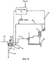
Фиг.6 показан пример осуществления с регулировкой влажности воздуха в пневмосепараторе.6 shows an example implementation with adjustable humidity in the air separator.
В общем случае пневматическая сепарационная установка (Фиг.1) состоит из пневмосепаратора 1, циклона 2, фильтра 3, вентилятора 4, соединяющих эти агрегаты трубопроводов или каналов 5, а также подающих и отводящих устройств для загрузки 6а, мелкой фракции 6b и грубой фракции 6с. Грубая фракция выпускается через выпускное отверстие 6с для грубой фракции. В циклоне 2 мелкая фракция, которая чаще всего представляет собой желаемый порошковый продукт, отделяется от сепарирующего воздуха и транспортируется далее посредством шнекового транспортера 5с. Отходящий воздух из сепаратора или соответственно циклона очищается от пыли в фильтре 3 и посредством вентилятора 4 отсасывается наружу, пыль мелкой фракции направляется в шнековый транспортер. Впускное отверстие 6d свежего воздуха может находиться непосредственно возле корпуса сепаратора или на предварительно включенном впускном канале свежего воздуха. В зависимости от конструкции пневмосепаратора в пневмосепаратор, например, для уплотнения поступает также так называемый запирающий воздух.In the General case, the pneumatic separation unit (Figure 1) consists of an
В соответствии с изобретением относительная влажность воздуха, используемого для сепарации, удерживается в диапазоне от 15 до 35%. В соответствии с фиг.1 для этой цели вода в виде пара или капель подается распылением в точке А во всосанный свежий воздух, а именно, во впускное отверстие 6d свежего воздуха.In accordance with the invention, the relative humidity of the air used for separation is kept in the range from 15 to 35%. In accordance with FIG. 1, for this purpose, water in the form of steam or droplets is sprayed at point A into the fresh air sucked in, namely, into the
На Фиг.2 показан пример осуществления, в котором уже известным способом часть потока выходящей из циклона 2 воздушно-порошковой смеси за вентилятором 4а циклона через трубопроводы или каналы 5а возвращается к впускному отверстию 6d свежего воздуха пневмосепаратора. При этом преимущество заключается в том, что вода, необходимая для увлажнения и охлаждения воздуха, используемого для сепарации, добавляется в точке В, а именно в соединительный трубопровод между вентилятором 4а циклона и впускным отверстием 6d свежего воздуха, так как получается достаточно длинный путь для распыления воды. Но и при этой схеме можно вполне успешно подавать воду распылением непосредственно во впускное отверстие 6d свежего воздуха.Figure 2 shows an embodiment in which, in a known manner, a part of the flow of the air-powder
На Фиг.3 показан пример осуществления, в котором как часть потока воздушно-порошковой смеси 5а, выходящей из циклона, так и часть потока отходящего воздуха из фильтра 5b возвращается во впускное отверстие 6d свежего воздуха пневмосепаратора. Преимущество при этом заключается в том, что вода, необходимая для увлажнения и охлаждения воздуха, используемого для сепарации, добавляется в поток возвратного воздуха из фильтра 3 в точке С, а именно, в соединительный трубопровод между вентилятором 4 и впускным отверстием 6d свежего воздуха, так как при этом в возвратном воздухе более не содержится частиц пыли, которые могут коагулировать с каплями и затем как грубые влажные частицы нарушить процесс. При такой подаче воздуха вода, а при необходимости только одна часть потока, также может вполне успешно подаваться распылением непосредственно во впускное отверстие 6d свежего воздуха.Figure 3 shows an embodiment in which both a part of the flow of the air-
Согласно примеру выполнения по фиг.4 во впускное отверстие 4d для свежего воздуха пневмосепаратора 1 возвращается лишь одна часть воздуха, отходящего из фильтра. Здесь преимуществом оказалось то, что вода, необходимая для увлажнения и охлаждения, подается в возвратный воздух в точке С, а именно в соединительный трубопровод 5b (т.е. обратный канал) между вентилятором 4 и впускным отверстием 4d для свежего воздуха.According to the exemplary embodiment of FIG. 4, only one part of the air leaving the filter is returned to the fresh air inlet 4d of the
Согласно Фиг.5 пневмосепаратор 1 связан непосредственно с аэрируемой мельницей 7, и отходящий воздух из мельницы по трубопроводам 8 подается к впускному отверстию свежего воздуха пневмосепаратора. Преимущество при этом заключается в том, что увлажнение воздуха происходит уже на входе в мельницу. Это мероприятие может также комбинироваться с вышеназванными примерами осуществления.According to Figure 5, the
На Фиг.6 принципиально поясняется, как может проводиться регулировка в примере осуществления по Фиг.4. Относительная влажность и температура отходящего воздуха из сепаратора измеряются за вентилятором 4 фильтра посредством сенсоров 10, а температура воздуха на выходе из пневмосепаратора посредством сенсора 9. Измерение относительной влажности лучше проводить в очищенном от пыли воздухе. По этим измеренным значениям в регуляторе 11 на основании известных зависимостей между температурой и подачей воды происходит расчет относительной влажности в самом сепараторе, и в соответствии с этим подача воды в обратный канал 5b для возвратного воздуха подстраивается таким образом, чтобы в сепараторе 1 установилась желательная относительная влажность.Fig.6 fundamentally explains how the adjustment can be carried out in the embodiment of Fig.4. The relative humidity and temperature of the exhaust air from the separator are measured behind the
С помощью установок, соответствующих приведенным выше фигурам, был проведен ряд различных испытаний, которые привели к следующим результатам.Using the settings corresponding to the above figures, a number of different tests were carried out, which led to the following results.
1. Параметры классификации при испытании с кондиционированным воздухом:1. Classification parameters for an air-conditioned test:
Через час эксплуатации на смотровой дверце установки образование скорлупы не обнаружено.After an hour of operation, no shell formation was detected on the inspection door of the unit.
2. Параметры классификации при испытании с некондиционированным воздухом:2. Classification parameters for testing with non-conditioned air:
Через час эксплуатации на смотровой дверце установки обнаружено образование скорлупы.After an hour of operation, shell formation was detected on the inspection door of the unit.
3. Параметры классификации при испытании с кондиционированным воздухом:3. Classification parameters for the air-conditioned test:
Через час эксплуатации на смотровой дверце установки образование скорлупы не обнаружено.After an hour of operation, no shell formation was detected on the inspection door of the unit.
4. Параметры классификации при испытании с некондиционированным воздухом:4. Classification parameters for testing with non-conditioned air:
Через час эксплуатации на смотровой дверце установки обнаружено небольшое образование скорлупы.After an hour of operation, a small shell formation was found on the inspection door of the unit.
5. Параметры классификации при испытании с кондиционированным воздухом:5. Classification parameters for the air-conditioned test:
Через час эксплуатации на смотровой дверце установки образование скорлупы не обнаружено.After an hour of operation, no shell formation was detected on the inspection door of the unit.
6. Параметры классификации при испытании с некондиционированным воздухом:6. Classification parameters for testing with non-air:
Через час эксплуатации на смотровой дверце установки обнаружены первые признаки образования скорлупы.After an hour of operation, the first signs of shell formation were found on the inspection door of the unit.
СПИСОК ПОЗИЦИЙLIST OF POSITIONS
1 Пневмосепаратор1 pneumatic separator
2 Циклон2 Cyclone
3 Фильтр3 Filter
4 Вентилятор4 fan
4а Вентилятор циклона4a Cyclone Fan
5/5а Каналы5 / 5a channels
5b Обратный канал от фильтра 3 к сепаратору 15b Return channel from
5с Шнековый транспортер для мелкой фракции5c Screw conveyor for fine fraction
6 Подводящие и отводящие устройства6 Inlet and outlet devices
6а Загрузка-подача в сепаратор 16a loading-feeding in the
6b Отвод мелкой фракции из сепаратора6b Discharge of fine fraction from the separator
6с Отвод грубой фракции из сепаратора6c Removal of coarse fraction from the separator
6d Впускное отверстие свежего воздуха в сепаратор6d Fresh air inlet to the separator
7 Мельница для сухого сырья7 Mill for dry raw materials
8 Трубы между мельницей 7 и отверстием впуска свежего воздуха 6d8 Pipes between
9 Сенсор температуры9 temperature sensor
10 Сенсор температуры и относительной влажности10 Temperature and relative humidity sensor
11 Регулятор.11 Regulator.
Claims (8)
Applications Claiming Priority (2)
| Application Number | Priority Date | Filing Date | Title |
|---|---|---|---|
| DE102006053356A DE102006053356B4 (en) | 2006-11-10 | 2006-11-10 | Process for the preparation of fine mineral powder products |
| DE102006053356.9 | 2006-11-10 |
Publications (2)
| Publication Number | Publication Date |
|---|---|
| RU2009122189A RU2009122189A (en) | 2010-12-20 |
| RU2459675C2 true RU2459675C2 (en) | 2012-08-27 |
Family
ID=39277651
Family Applications (1)
| Application Number | Title | Priority Date | Filing Date |
|---|---|---|---|
| RU2009122189/03A RU2459675C2 (en) | 2006-11-10 | 2007-11-12 | Method of producing fine-powder mineral products |
Country Status (18)
| Country | Link |
|---|---|
| US (1) | US8393557B2 (en) |
| EP (1) | EP2081699B1 (en) |
| JP (1) | JP5147023B2 (en) |
| KR (1) | KR101385837B1 (en) |
| CN (1) | CN101600514B (en) |
| CA (1) | CA2668949C (en) |
| DE (1) | DE102006053356B4 (en) |
| DK (1) | DK2081699T3 (en) |
| ES (1) | ES2547482T3 (en) |
| HU (1) | HUE028127T2 (en) |
| IN (1) | IN266869B (en) |
| MX (1) | MX2009004909A (en) |
| NO (1) | NO339418B1 (en) |
| PL (1) | PL2081699T3 (en) |
| PT (1) | PT2081699E (en) |
| RU (1) | RU2459675C2 (en) |
| SI (1) | SI2081699T1 (en) |
| WO (1) | WO2008055495A2 (en) |
Families Citing this family (8)
| Publication number | Priority date | Publication date | Assignee | Title |
|---|---|---|---|---|
| US8726720B2 (en) * | 2010-05-10 | 2014-05-20 | Thermo Fisher Scientific Inc. | Particulate matter monitor |
| CN102773173A (en) * | 2012-07-30 | 2012-11-14 | 四川石棉巨丰粉体有限公司 | Grading method of ground limestone |
| CN104308165A (en) * | 2014-08-29 | 2015-01-28 | 北京京磁永磁科技发展有限公司 | Jet mill |
| US10287171B2 (en) * | 2016-05-05 | 2019-05-14 | Rec Silicon Inc | Tumbling device for the separation of granular polysilicon and polysilicon powder |
| IT201700095977A1 (en) * | 2017-08-24 | 2019-02-24 | Polibiotech Srl | "METHOD AND GUIDED GAS FLOW SYSTEM FOR THE PRODUCTION, SEPARATION AND CLASSIFICATION OF SMALL PARTICLES", |
| JP2018114505A (en) * | 2018-05-01 | 2018-07-26 | 株式会社リョーシン | Wind power selection system |
| JP6612418B1 (en) * | 2018-11-26 | 2019-11-27 | 株式会社金星 | Gas conveyance type fine powder quantitative supply method and system |
| KR102294881B1 (en) * | 2020-03-09 | 2021-08-26 | 김지영 | Feed composition containing crushed mineral ore |
Citations (11)
| Publication number | Priority date | Publication date | Assignee | Title |
|---|---|---|---|---|
| DE1804158U (en) * | 1959-09-07 | 1960-01-14 | Theodor Kuypers | FREE HANGING, MOVABLE ROPE CLAMP. |
| DE1197734B (en) * | 1956-09-10 | 1965-07-29 | Lorraine Escaut Sa | Method and device for regulating a mill with air flow separation |
| GB2014711A (en) * | 1978-02-10 | 1979-08-30 | Italcementi Spa | Installation for converting raw-material slurries into Portland-cement clinker |
| DE3040996A1 (en) * | 1980-10-31 | 1982-06-09 | Chemische Werke Hüls AG, 4370 Marl | Grading electrostatically charged powders esp. of plastics - using controlled humidity in carrier gas stream conveying powder through sieve |
| SU1384334A1 (en) * | 1986-05-27 | 1988-03-30 | Днепропетровский горный институт им.Артема | Gas/jet mill |
| SU1527462A1 (en) * | 1988-03-31 | 1989-12-07 | Всесоюзный Научно-Исследовательский И Проектный Институт Промышленности Асбестоцементных Изделий | Installation for producing claydite sand and dehydrated clay powder |
| SU1755946A1 (en) * | 1990-06-07 | 1992-08-23 | Уральский политехнический институт им.С.М.Кирова | Pneumatic classifier |
| RU2065772C1 (en) * | 1993-12-09 | 1996-08-27 | Виктор Александрович Ильичев | Method and device for grinding mineral powdery materials |
| RU38452U1 (en) * | 2004-04-01 | 2004-06-20 | Закрытое акционерное общество "Патентные услуги" | TECHNOLOGICAL LINE FOR PRODUCTION OF MICROPOWDERS |
| RU2277980C2 (en) * | 2004-06-10 | 2006-06-20 | Тольяттинский государственный университет | Powder material producing method |
| RU2327534C2 (en) * | 2006-04-03 | 2008-06-27 | Валентин Николаевич Аполицкий | Method of dry classification of powder material |
Family Cites Families (12)
| Publication number | Priority date | Publication date | Assignee | Title |
|---|---|---|---|---|
| GB953690A (en) * | 1963-01-14 | 1964-03-25 | Masuda Senichi | Improvements in dust classifiers |
| FR1585405A (en) * | 1968-05-10 | 1970-01-23 | ||
| DE1804158B2 (en) | 1968-10-19 | 1976-06-16 | WIND VISION PROCEDURE | |
| DE2642884C2 (en) | 1976-09-23 | 1985-10-10 | Rumpf, geb. Strupp, Lieselotte Clara, 7500 Karlsruhe | Method and device for dispersing and pneumatically feeding fine-grained material into the viewing zone of an air classifier |
| DE3011910C2 (en) | 1980-03-27 | 1982-05-19 | Stephan Dipl.-Ing. 3392 Clausthal-Zellerfeld Röthele | Air classifier with means for cleaning off caked deposits on the inner walls of the classifying room |
| JPS61167470A (en) * | 1985-01-21 | 1986-07-29 | Toyota Motor Corp | Method for classifying ceramic powder |
| DE3815763A1 (en) * | 1988-05-09 | 1989-11-23 | Kloeckner Humboldt Deutz Ag | METHOD AND SYSTEM FOR DRYING DAMP MATERIALS, SUCH AS CEMENT RAW MATERIALS BY MEANS OF A GAS FLOW |
| JP2869088B2 (en) * | 1989-08-04 | 1999-03-10 | 株式会社クラレ | Purification method of mica powder |
| JP3531784B2 (en) * | 1997-05-28 | 2004-05-31 | 株式会社リコー | Airflow classifier |
| DE19806895C2 (en) * | 1998-02-19 | 2002-10-24 | Pfeiffer Ag Geb | Method and device for optimizing the milling bed of roller-type bowl mills |
| JP2003088810A (en) * | 2001-09-20 | 2003-03-25 | Fuji Heavy Ind Ltd | Sorting method for shredder dust |
| US7757976B2 (en) * | 2007-02-07 | 2010-07-20 | Unimin Corporation | Method of processing nepheline syenite powder to produce an ultra-fine grain size product |
-
2006
- 2006-11-10 DE DE102006053356A patent/DE102006053356B4/en not_active Expired - Fee Related
-
2007
- 2007-11-12 MX MX2009004909A patent/MX2009004909A/en active IP Right Grant
- 2007-11-12 CA CA2668949A patent/CA2668949C/en active Active
- 2007-11-12 SI SI200731689T patent/SI2081699T1/en unknown
- 2007-11-12 US US12/514,175 patent/US8393557B2/en active Active
- 2007-11-12 DK DK07846319.7T patent/DK2081699T3/en active
- 2007-11-12 CN CN2007800417338A patent/CN101600514B/en not_active Expired - Fee Related
- 2007-11-12 JP JP2009535558A patent/JP5147023B2/en not_active Expired - Fee Related
- 2007-11-12 IN IN2017CHN2009 patent/IN266869B/en unknown
- 2007-11-12 PT PT78463197T patent/PT2081699E/en unknown
- 2007-11-12 KR KR1020097008805A patent/KR101385837B1/en not_active IP Right Cessation
- 2007-11-12 PL PL07846319T patent/PL2081699T3/en unknown
- 2007-11-12 HU HUE07846319A patent/HUE028127T2/en unknown
- 2007-11-12 ES ES07846319.7T patent/ES2547482T3/en active Active
- 2007-11-12 EP EP07846319.7A patent/EP2081699B1/en active Active
- 2007-11-12 RU RU2009122189/03A patent/RU2459675C2/en not_active IP Right Cessation
- 2007-11-12 WO PCT/DE2007/002035 patent/WO2008055495A2/en active Application Filing
-
2009
- 2009-05-22 NO NO20091982A patent/NO339418B1/en not_active IP Right Cessation
Patent Citations (11)
| Publication number | Priority date | Publication date | Assignee | Title |
|---|---|---|---|---|
| DE1197734B (en) * | 1956-09-10 | 1965-07-29 | Lorraine Escaut Sa | Method and device for regulating a mill with air flow separation |
| DE1804158U (en) * | 1959-09-07 | 1960-01-14 | Theodor Kuypers | FREE HANGING, MOVABLE ROPE CLAMP. |
| GB2014711A (en) * | 1978-02-10 | 1979-08-30 | Italcementi Spa | Installation for converting raw-material slurries into Portland-cement clinker |
| DE3040996A1 (en) * | 1980-10-31 | 1982-06-09 | Chemische Werke Hüls AG, 4370 Marl | Grading electrostatically charged powders esp. of plastics - using controlled humidity in carrier gas stream conveying powder through sieve |
| SU1384334A1 (en) * | 1986-05-27 | 1988-03-30 | Днепропетровский горный институт им.Артема | Gas/jet mill |
| SU1527462A1 (en) * | 1988-03-31 | 1989-12-07 | Всесоюзный Научно-Исследовательский И Проектный Институт Промышленности Асбестоцементных Изделий | Installation for producing claydite sand and dehydrated clay powder |
| SU1755946A1 (en) * | 1990-06-07 | 1992-08-23 | Уральский политехнический институт им.С.М.Кирова | Pneumatic classifier |
| RU2065772C1 (en) * | 1993-12-09 | 1996-08-27 | Виктор Александрович Ильичев | Method and device for grinding mineral powdery materials |
| RU38452U1 (en) * | 2004-04-01 | 2004-06-20 | Закрытое акционерное общество "Патентные услуги" | TECHNOLOGICAL LINE FOR PRODUCTION OF MICROPOWDERS |
| RU2277980C2 (en) * | 2004-06-10 | 2006-06-20 | Тольяттинский государственный университет | Powder material producing method |
| RU2327534C2 (en) * | 2006-04-03 | 2008-06-27 | Валентин Николаевич Аполицкий | Method of dry classification of powder material |
Also Published As
| Publication number | Publication date |
|---|---|
| PT2081699E (en) | 2015-10-30 |
| CA2668949A1 (en) | 2008-05-15 |
| WO2008055495A3 (en) | 2009-01-22 |
| DK2081699T3 (en) | 2015-12-07 |
| US8393557B2 (en) | 2013-03-12 |
| WO2008055495A2 (en) | 2008-05-15 |
| KR101385837B1 (en) | 2014-04-16 |
| EP2081699A2 (en) | 2009-07-29 |
| KR20090089293A (en) | 2009-08-21 |
| IN266869B (en) | 2015-06-10 |
| CN101600514A (en) | 2009-12-09 |
| US20100294863A1 (en) | 2010-11-25 |
| PL2081699T3 (en) | 2016-01-29 |
| NO20091982L (en) | 2009-06-09 |
| RU2009122189A (en) | 2010-12-20 |
| MX2009004909A (en) | 2009-07-24 |
| CN101600514B (en) | 2013-08-14 |
| CA2668949C (en) | 2016-01-05 |
| ES2547482T3 (en) | 2015-10-06 |
| JP5147023B2 (en) | 2013-02-20 |
| HUE028127T2 (en) | 2016-12-28 |
| SI2081699T1 (en) | 2015-10-30 |
| DE102006053356B4 (en) | 2011-03-17 |
| DE102006053356A1 (en) | 2008-05-15 |
| JP2010509041A (en) | 2010-03-25 |
| EP2081699B1 (en) | 2015-08-19 |
| NO339418B1 (en) | 2016-12-12 |
Similar Documents
| Publication | Publication Date | Title |
|---|---|---|
| RU2459675C2 (en) | Method of producing fine-powder mineral products | |
| CN107921483B (en) | Method for separating a granular mixture from a flowing medium and device for carrying out said method | |
| US7300007B2 (en) | Circulating grinding plant comprising a mill and a sifter | |
| JPS59196726A (en) | Continuous fluidized layer type granulating apparatus | |
| CZ283804B6 (en) | Grinding process of raw brown coal | |
| US3524544A (en) | Milling plant for sifting damp material | |
| CN108325715A (en) | Feed Manufacturing is classified wind with crushing material and send cooling system | |
| CN205598679U (en) | High -speed centrifugal spraying drier | |
| CN106075941A (en) | A kind of spray drying device | |
| CN204063854U (en) | A kind of expansion drying mechanism and type expansion drier | |
| US3383774A (en) | Apparatus and method for treating pulverulent or granular material | |
| EP0549137B1 (en) | Method for grinding of material | |
| CN106039746A (en) | Wall-sticking-proof spraying dryer | |
| RU2277980C2 (en) | Powder material producing method | |
| RU2324872C1 (en) | Spray drier | |
| WO1998036840A1 (en) | Equipment and method for producing ultra fine dry powders by means of a high-energy power gas | |
| CN207324107U (en) | A kind of three fluid spray dryers | |
| JP2002335861A (en) | Electrostatic separator | |
| SU768485A1 (en) | Plant for dedusting and sieving wet materials | |
| SU876214A1 (en) | Pneumatic vibratory dust control apparatus | |
| RU2306502C1 (en) | Spraying drier | |
| RU2320240C1 (en) | Drier with inert head | |
| CN115041290A (en) | Micro powder production system and production method and dry powder making system | |
| SU1006518A1 (en) | Method for preparing white limestone for agglomeration process | |
| JPH05301079A (en) | Removing equipment for dust of crushed sand |
Legal Events
| Date | Code | Title | Description |
|---|---|---|---|
| MM4A | The patent is invalid due to non-payment of fees |
Effective date: 20181113 |