RU2457504C1 - Method of scanning space using optoelectronic system - Google Patents
Method of scanning space using optoelectronic system Download PDFInfo
- Publication number
- RU2457504C1 RU2457504C1 RU2011117183/07A RU2011117183A RU2457504C1 RU 2457504 C1 RU2457504 C1 RU 2457504C1 RU 2011117183/07 A RU2011117183/07 A RU 2011117183/07A RU 2011117183 A RU2011117183 A RU 2011117183A RU 2457504 C1 RU2457504 C1 RU 2457504C1
- Authority
- RU
- Russia
- Prior art keywords
- scanning
- frame
- space
- matrix photodetector
- plane
- Prior art date
Links
- 238000000034 method Methods 0.000 title claims abstract description 28
- 230000005693 optoelectronics Effects 0.000 title claims abstract description 15
- 239000011159 matrix material Substances 0.000 claims abstract description 20
- 230000010355 oscillation Effects 0.000 claims abstract description 6
- 230000003534 oscillatory effect Effects 0.000 claims abstract description 5
- 239000000654 additive Substances 0.000 claims abstract description 4
- 230000000996 additive effect Effects 0.000 claims abstract description 4
- 238000009825 accumulation Methods 0.000 abstract description 9
- 230000035945 sensitivity Effects 0.000 abstract description 5
- 230000015572 biosynthetic process Effects 0.000 abstract description 4
- 230000000694 effects Effects 0.000 abstract 1
- 239000000126 substance Substances 0.000 abstract 1
- 230000003287 optical effect Effects 0.000 description 14
- 238000012552 review Methods 0.000 description 7
- 229920005558 epichlorohydrin rubber Polymers 0.000 description 6
- 239000002131 composite material Substances 0.000 description 2
- RPYRLXFYICBMOZ-CWSCBRNRSA-N (2s,3s,4s)-3-(carboxymethyl)-4-(2-methoxyphenyl)pyrrolidine-2-carboxylic acid Chemical group COC1=CC=CC=C1[C@@H]1[C@H](CC(O)=O)[C@@H](C(O)=O)NC1 RPYRLXFYICBMOZ-CWSCBRNRSA-N 0.000 description 1
- 238000013459 approach Methods 0.000 description 1
- 244000309464 bull Species 0.000 description 1
- 230000001364 causal effect Effects 0.000 description 1
- 230000002301 combined effect Effects 0.000 description 1
- 238000001514 detection method Methods 0.000 description 1
- 238000001914 filtration Methods 0.000 description 1
- 239000012634 fragment Substances 0.000 description 1
- 230000005855 radiation Effects 0.000 description 1
- 238000001931 thermography Methods 0.000 description 1
Landscapes
- Studio Devices (AREA)
Abstract

Description
Изобретение относится к области оптико-электронного приборостроения и может быть использовано в прицельно-обзорных оптико-электронных системах, в частности в теплопеленгаторах кругового обзора с матричным фотоприемным устройством.The invention relates to the field of optoelectronic instrumentation and can be used in sighting and survey optoelectronic systems, in particular in circular direction finders with a matrix photodetector.
Известен наиболее используемый в настоящее время способ обзора пространства, при котором оптико-электронная система, включающая в себя приемную оптическую систему, сопряженную с матричным фотоприемным устройством (МФПУ), устанавливается на двухкоординатную поворотную платформу, которая работает либо в режиме панорамной съемки со сканированием зоны обзора, либо в режиме переброса из точки в точку [Волков В.Г., Ковалев А.В., Федчишин В.Г. «Вертолетные оптико-электронные системы наблюдения и разведки», - ж. «Спецтехника», №3, 2001 г., стр.1-10; «Тепловизионные приборы нового поколения», - ж. «Спецтехника», №6, 2001 г., стр.16-20 и №1, 2002 г., стр.18-26].The currently most widely used space survey method is known, in which an optoelectronic system including a receiving optical system coupled to an array photodetector (MFP) is mounted on a two-axis rotary platform that works either in panoramic mode with scanning the viewing area or in the mode of transfer from point to point [Volkov V.G., Kovalev A.V., Fedchishin V.G. "Helicopter optoelectronic surveillance and reconnaissance systems," - g. "Special equipment", No. 3, 2001, pp. 1-10; “Thermal imaging devices of a new generation”, - g. "Special equipment", No. 6, 2001, pp. 16-20 and No. 1, 2002, pp. 18-26].
Недостатком этого способа является, в первом случае, малая скорость обзора, ограниченная отношением углового разрешения к требуемому времени накопления сигнала. Во втором случае необходима команда внешнего целеуказания для наведения оптико-электронной системы (ОЭС) в заданный сектор пространства, а для сплошного просмотра зоны обзора этот режим не применяется ввиду большой инерционности и механических нагрузок на приводы системы.The disadvantage of this method is, in the first case, the low speed of the review, limited by the ratio of the angular resolution to the required signal accumulation time. In the second case, an external target designation command is needed to guide the optoelectronic system (OES) into a given sector of space, and for continuous viewing of the viewing area this mode is not applied due to the large inertia and mechanical stresses on the system drives.
Известны также способы обзора пространства [Елизаров А.В., Куртов А.В., Соломатин В.А., Якушенков Ю.Г. «Обзорнопанорамные оптико-электронные системы». - Изв. Вузов, сер. Приборостроение, 2002 г., т.45, №2, стр.37-44], классифицируемые как способы обзора с составным полем зрения, способ, который носит название «Мозаика», и способ на базе использования панорамных оптических систем.There are also known methods of viewing space [Elizarov A.V., Kurtov A.V., Solomatin V.A., Yakushenkov Yu.G. "Panoramic Panoramic Optoelectronic Systems". - Izv. Universities, ser. Instrument Engineering, 2002, vol. 45, No. 2, pp. 37-44], classified as viewing methods with a composite field of view, a method called “Mosaic”, and a method based on the use of panoramic optical systems.
Способ обзора с составным полем зрения включает в себя разделение зоны обзора на совмещенные сектора обзора, каждый из которых контролируется отдельным МФПУ, снабженным собственным объективом.A viewing method with a composite field of view includes dividing the viewing area into combined viewing sectors, each of which is controlled by a separate MFP equipped with its own lens.
Недостатком этого способа является громоздкость его практической реализации, так как для получения углового разрешения и дальности обнаружения, сравнимыми с аналогичными параметрами рассмотренных выше систем, потребуется несколько десятков таких элементарных ОЭС.The disadvantage of this method is the cumbersomeness of its practical implementation, since in order to obtain the angular resolution and detection range comparable with the similar parameters of the systems considered above, several dozen such elementary ECOs are required.
Способ "Мозаика" предусматривает также многоканальное исполнение, причем каналы развернуты по азимуту относительно друг друга и каждый канал снабжен приводом угломестного сканирования с шаговым приводом сканирующего зеркала. Недостатком такого способа обзора также является сложность осуществления.The Mosaic method also provides for multi-channel execution, with the channels being turned in azimuth relative to each other and each channel is equipped with an elevation scan drive with a step-by-step scanning mirror drive. The disadvantage of this review method is also the difficulty of implementation.
ОЭС при реализации способа с использованием панорамной оптики строится на базе одного МФПУ с широкоугольной оптической системой, обеспечивающей обзор практически всей полусферы. Эти системы достаточно компактны, однако, имеют низкую чувствительность и угловое разрешение. Способ используется, в основном, для определения направления на высокоэнергетические источники излучения.OES when implementing the method using panoramic optics is based on one MFP with a wide-angle optical system that provides an overview of almost the entire hemisphere. These systems are quite compact, however, they have low sensitivity and angular resolution. The method is used mainly to determine the direction of high-energy radiation sources.
Наиболее близким способом того же назначения, что и заявляемый, по совокупности существенных признаков, является способ обзора пространства, реализуемый в процессе функционирования теплопеленгатора, описанного в [Патент RU №2396574. Бюл. Изобр., №22, 2010], выбранный нами в качестве прототипа. Способ предусматривает обзор пространства двухкоординатным сканирующим зеркалом и формирование временных интервалов, в которых скорости вращения и сдвига изображения в плоскости неподвижного матричного фотоприемного устройства близки или равны нулю. Последнее достигается путем введения специального двухкоординатного компенсирующего устройства в оптический тракт теплопеленгатора.The closest method to the same purpose as the claimed one, according to the set of essential features, is a method for reviewing the space, implemented in the process of functioning of the direction finder described in [Patent RU No. 2396574. Bull. Invent., No. 22, 2010], selected by us as a prototype. The method involves a review of the space by a two-coordinate scanning mirror and the formation of time intervals in which the speeds of rotation and shift of the image in the plane of the stationary matrix photodetector are close to or equal to zero. The latter is achieved by introducing a special two-coordinate compensating device in the optical path of the heat finder.
Накопление сигналов осуществляется во временные интервалы, в которых скорости вращения и сдвига изображения близки или равны нулю, что позволяет формировать кадр практически без сдвига изображения. Компенсирующее устройство представляет собой двухкоординатный дефлектор, совершающий управляемые колебания относительно двух взаимно перпендикулярных осей.The accumulation of signals is carried out at time intervals in which the rotation speed and image shift are close to or equal to zero, which allows you to form a frame with virtually no image shift. The compensating device is a two-coordinate deflector that performs controlled oscillations relative to two mutually perpendicular axes.
К причинам, препятствующим достижению указанного ниже технического результата при использовании известного способа-прототипа, относятся следующие.The reasons that impede the achievement of the following technical result when using the known prototype method include the following.
В процессе сканирования зоны обзора происходит вращение изображения в плоскости МФПУ, что снижает чувствительность и угловое разрешение системы, или, при увеличении фокусного расстояния оптической системы, уменьшает скорость сканирования. Требуются также значительные вычислительные ресурсы для цифровой компенсации поворота изображения. Кроме этого, применение цифровой компенсации поворота изображения приводит к существенно низкому коэффициенту использования элементов матрицы.In the process of scanning the viewing area, the image rotates in the MPPU plane, which reduces the sensitivity and angular resolution of the system, or, with an increase in the focal length of the optical system, reduces the scanning speed. Significant computing resources are also required for digital image rotation compensation. In addition, the use of digital compensation for image rotation leads to a significantly low utilization of matrix elements.
К недостаткам данного способа следует отнести также и то, что он реализуется при сравнительно невысокой кадровой частоте. Это обуславливает пониженную скорость обзора пространства.The disadvantages of this method should also include the fact that it is implemented at a relatively low frame rate. This leads to a reduced speed of viewing the space.
Задачей изобретения является повышение скорости обзора пространства оптико-электронной системой с увеличением углового разрешения.The objective of the invention is to increase the speed of the review of space by an optical-electronic system with increasing angular resolution.
Техническим результатом изобретения является обеспечение оптико-электронной системой обзора пространства с высокими кадровой частотой и угловым разрешением при увеличении времени накопления сигналов МФПУ и повышении чувствительности аппаратуры.The technical result of the invention is the provision of an optical-electronic system for viewing the space with a high frame rate and angular resolution while increasing the accumulation time of the MFP signals and increasing the sensitivity of the equipment.
Указанный выше технический результат достигается тем, что в способе обзора пространства оптико-электронной системой, включающем сканирование пространства по азимутальной и угломестной координате, формирование изображения зоны обзора пространства в плоскости матричного фотоприемного устройства, покадровое экспонирование фоточувствительных элементов матричного фотоприемного устройства, в соответствии с заявляемым техническим решением осуществляют перевод изображения зоны обзора из вращающейся системы координат в неподвижную систему координат, связанную с плоскостью неподвижного матричного фотоприемного устройства, сканирование пространства по азимутальной координате осуществляют с угловой скоростью, равной The above technical result is achieved by the fact that in the method of viewing space by an optical-electronic system, including scanning the space in azimuth and elevation coordinate, forming an image of the viewing area of the space in the plane of the matrix photodetector, frame-by-frame exposure of the photosensitive elements of the matrix photodetector, in accordance with the claimed technical The solution translates the image of the field of view from a rotating coordinate system to a fixed system Thread coordinates associated with the plane of the stationary matrix photodetector, scanning of the azimuthal coordinate space performed with an angular velocity equal to
ωаз=Δφаз·fк, ω az = Δφ az · f k ,
где ωаз - угловая скорость сканирования;where ω az - the angular velocity of the scan;
Δφаз - шаг азимутального сканирования, меньший или равный угловому размеру кадра;Δφ az - azimuthal scanning step less than or equal to the angular size of the frame;
fк - кадровая частота матричного фотоприемного устройства; f to - the frame frequency of the matrix photodetector;
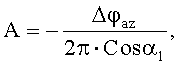
дополнительно формируют колебательную составляющую движения изображения в плоскости матричного фотоприемного устройства в направлении азимутального сканирования и удовлетворяющую соотношению Δωаз=A·(2πfk)·Cos(2πfкt), где Δωаз - аддитивная составляющая угловой скорости сканирования, изменяющаяся во времени по гармоническому закону, A - амплитуда колебаний, удовлетворяющая условию 


Совокупность вышеизложенных признаков изобретения связана причинно-следственной связью с техническим результатом изобретения.The combination of the foregoing features of the invention is associated with a causal relationship with the technical result of the invention.
В процессе обзора пространства оптико-электронной системой осуществляется сканирование пространства по азимутальной φ и угломестной θ координате. При реализации способа осуществляют перевод изображения зоны обзора из вращающейся системы координат в неподвижную систему координат, связанную с плоскостью фоточувствительных элементов матричного фотоприемного устройства, входящего в состав оптико-электронной системы (далее для краткости - с плоскостью МФПУ). Сканирование пространства по азимутальной координате осуществляют с угловой скоростью, связанной с угловым размером кадра и кадровой частотой матричного фотоприемного устройства. Вводится колебательная составляющая движения изображения в плоскости МФПУ в направлении азимутального сканирования, амплитуда которой находится в строгом соотношении с кадровой частотой МФПУ, угловым размером кадра и радиусом кружка рассеяния приемного объектива ОЭС, формирующего изображение в плоскости МФПУ. Выполнение указанных действий и режимов их осуществления обеспечивает формирование временных интервалов, связанных с кадровой частотой МФПУ, внутри которых изображение стабилизировано в пределах кружка рассеяния. Если осуществить покадровое экспонирование фоточувствительных элементов МФПУ в эти определяемые всей предыдущей последовательностью действий моменты времени, то, как нами было показано теоретически и подтверждено экспериментально, за время покадрового экспонирования
На Фиг.1 показана траектория микросканирования φ(t) по азимутальной координате φ(t)=Δφаз·fк·t+ASin(2π·fк·t) в интервале
Способ реализуется в следующей последовательности действий.The method is implemented in the following sequence of actions.
Оптико-электронная система ведет обзор контролируемого пространства. Двухкоординатная сканирующая система осуществляет круговое сканирование по азимутальной координате со скоростью, определяемой кадровой частотой МФПУ и заданным размером кадра по азимутальной координате: ωаз=Δφаз·fк, Optoelectronic system reviews the controlled space. The two-coordinate scanning system performs circular scanning in the azimuthal coordinate at a speed determined by the frame frequency of the MFP and the specified frame size in the azimuthal coordinate: ω az = Δφ az · f k ,
здесь ωаз - угловая скорость сканирования;here ω az is the angular scanning speed;
Δφаз - шаг азимутального сканирования, меньший или равный угловому размеру кадра;Δφ az - azimuthal scanning step less than or equal to the angular size of the frame;
fк - кадровая частота матричного фотоприемного устройства.f to - the frame frequency of the matrix photodetector.
На выходе сканирующей системы известными оптическими методами производится компенсация вращения изображения относительно плоскости неподвижного МФПУ. Такая компенсация может осуществляться вращением призмы Дове, вращением уголкового зеркала, встроенного во входной телескоп приемной оптической системы, и т.д. В результате осуществляется перевод изображения зоны обзора из вращающейся системы координат в неподвижную систему координат, связанную с плоскостью МФПУ.The output of the scanning system by known optical methods compensates for the rotation of the image relative to the plane of the stationary MFP. Such compensation can be carried out by rotating the Dove prism, by rotating the corner mirror integrated in the input telescope of the receiving optical system, etc. As a result, the image of the viewing zone is transferred from a rotating coordinate system to a fixed coordinate system associated with the MPPU plane.
После компенсации поворота изображения формируют малые гармонические колебания оптической оси в направлении азимутального сканирования. Подходы к решению этой задачи известны. Например, можно использовать оптические клинья, размещаемые на оптической оси системы и выполненные с возможностью вращения вокруг оси с одинаковой угловой скоростью в противоположных направлениях. Нами были выведены строгие численные соотношения, связывающие параметры колебательного движения с кадровой частотой МФПУ, угловым размером кадра и радиусом кружка рассеяния приемного объектива оптико-электронной системы, формирующего изображение в плоскости МФПУ. Как было показано, колебательное движение изображения в плоскости МФПУ должно удовлетворять следующим соотношениям:After compensation of image rotation, small harmonic oscillations of the optical axis are formed in the direction of azimuthal scanning. Approaches to solving this problem are known. For example, you can use optical wedges placed on the optical axis of the system and configured to rotate around the axis with the same angular velocity in opposite directions. We have derived rigorous numerical relationships relating the parameters of the oscillatory motion with the frame rate of the MFP, the angular size of the frame, and the radius of the scattering circle of the receiving lens of the optoelectronic system forming the image in the plane of the MFP. As was shown, the oscillatory motion of the image in the plane of the MFP should satisfy the following relationships:
Δωаз=A·(2πfk)·Cos(2π·fк·t); 
где Δωаз - аддитивная составляющая угловой скорости сканирования, изменяющаяся во времени по гармоническому закону;where Δω az is the additive component of the angular scanning speed, which varies in time according to the harmonic law;
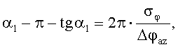
A - амплитуда колебаний, а параметр α1, лежащий в пределах π/2<α1<π, определяется из уравнения
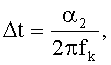
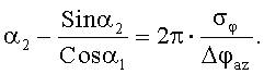
Подбирают интервал времени 
Численные оценки показывают, что при кадровой частоте fк=100 Гц, объективе с диафрагменным числом F/2 и относительной амплитуде микросканирования 
В оставшееся время кадра после экспонирования осуществляется считывание накопленных МФПУ сигналов, при этом оптическая ось ОЭС сдвигается на Δφаз, далее цикл формирования следующего кадра повторяется в описанной последовательности.In the remaining frame time after exposure, the accumulated MFPA signals are read, while the optical axis of the ECO is shifted by Δφ az , then the next frame formation cycle is repeated in the described sequence.
Таким образом, обзор контролируемого пространства осуществляется экспонированием последовательности сопряженных по угловым координатам и ориентированных в пространстве кадров с фрагментами контролируемого пространства, а скорость обзора определяется собственной кадровой частотой МФПУ. Способ позволяет осуществить обзор пространства с высокой кадровой частотой и угловым разрешением, позволяет увеличить времени накопления сигналов МФПУ и повысить чувствительность аппаратуры.Thus, the survey of the controlled space is carried out by exposing a sequence of frames conjugated in angular coordinates and oriented in space with fragments of the controlled space, and the speed of the review is determined by the intrinsic frame frequency of the MFP. The method allows you to review the space with a high frame rate and angular resolution, allows you to increase the accumulation time of the signals of the MFP and increase the sensitivity of the equipment.
Claims (1)
ωаз=Δφаз·fк,
где ωаз - угловая скорость сканирования;
Δφаз - шаг азимутального сканирования, меньший или равный угловому размеру кадра;
fк - кадровая частота матричного фотоприемного устройства;
дополнительно формируют колебательную составляющую движения изображения в плоскости матричного фотоприемного устройства в направлении азимутального сканирования и удовлетворяющую соотношению Δωаз=А·(2πfk)·Соs(2πfкt), где Δωаз - аддитивная составляющая угловой скорости сканирования, изменяющаяся во времени по гармоническому закону, А - амплитуда колебаний, удовлетворяющая условию

а параметр α1, лежащий в пределах π/2<α1<π, определяют из уравнения

где σφ - радиус кружка рассеяния объектива оптико-электронной системы, покадровое экспонирование осуществляют в интервале времени


ω az = Δφ az · f k ,
where ω az - the angular velocity of the scan;
Δφ az - azimuthal scanning step less than or equal to the angular size of the frame;
f to - the frame frequency of the matrix photodetector;
additionally form the oscillatory component of the image movement in the plane of the photodetector array in the direction of azimuthal scanning and satisfying the relation Δω az = A · (2πf k ) · Cos (2πf to t), where Δω az is the additive component of the angular scanning speed, which varies in time with respect to the harmonic law, A is the amplitude of the oscillations satisfying the condition
and the parameter α 1 lying within π / 2 <α 1 <π is determined from the equation
where σ φ is the radius of the scattering circle of the lens of the optoelectronic system, frame-by-frame exposure is performed in the time interval
Priority Applications (1)
| Application Number | Priority Date | Filing Date | Title |
|---|---|---|---|
| RU2011117183/07A RU2457504C1 (en) | 2011-04-15 | 2011-04-15 | Method of scanning space using optoelectronic system |
Applications Claiming Priority (1)
| Application Number | Priority Date | Filing Date | Title |
|---|---|---|---|
| RU2011117183/07A RU2457504C1 (en) | 2011-04-15 | 2011-04-15 | Method of scanning space using optoelectronic system |
Publications (1)
| Publication Number | Publication Date |
|---|---|
| RU2457504C1 true RU2457504C1 (en) | 2012-07-27 |
Family
ID=46850816
Family Applications (1)
| Application Number | Title | Priority Date | Filing Date |
|---|---|---|---|
| RU2011117183/07A RU2457504C1 (en) | 2011-04-15 | 2011-04-15 | Method of scanning space using optoelectronic system |
Country Status (1)
| Country | Link |
|---|---|
| RU (1) | RU2457504C1 (en) |
Cited By (3)
| Publication number | Priority date | Publication date | Assignee | Title |
|---|---|---|---|---|
| RU2696822C1 (en) * | 2019-01-28 | 2019-08-06 | Акционерное общество "Бортовые аэронавигационные системы" | Method for panoramic scanning of space with an optoelectronic system |
| CN114593736A (en) * | 2022-01-27 | 2022-06-07 | 中南大学 | Geographical positioning method, positioning error analysis method and system for swing-sweeping satellite |
| RU2845635C1 (en) * | 2025-02-03 | 2025-08-25 | федеральное государственное автономное образовательное учреждение высшего образования "Национальный исследовательский университет ИТМО" (Университет ИТМО) | Method for all-round view of space with optoelectronic system and device for its implementation |
Citations (7)
| Publication number | Priority date | Publication date | Assignee | Title |
|---|---|---|---|---|
| US4626100A (en) * | 1983-12-27 | 1986-12-02 | The United States Of America As Represented By The Secretary Of The Army | Wide field of view two-axis laser locator |
| RU2024896C1 (en) * | 1991-05-30 | 1994-12-15 | Шихер Яков Исаевич | Scanning system |
| US6608848B2 (en) * | 1998-06-01 | 2003-08-19 | Lambda Physik Ag | Method and apparatus for wavelength calibration |
| FR2912573A1 (en) * | 2007-02-13 | 2008-08-15 | Thales Sa | METHOD FOR DETECTING LASER PULSES USING A PHOTODETECTORS MATRIX |
| RU2354994C1 (en) * | 2007-10-29 | 2009-05-10 | Олег Фёдорович Меньших | Method of processing information in coherent laser locator with photodetector array |
| US20100091551A1 (en) * | 2008-10-10 | 2010-04-15 | Kabushiki Kaisha Toshiba | Semiconductor storage device |
| RU2396574C2 (en) * | 2008-09-04 | 2010-08-10 | Федеральное государственное унитарное предприятие "Производственное объединение "Уральский оптико-механический завод" имени Э.С. Яламова" | Thermal direction finder |
-
2011
- 2011-04-15 RU RU2011117183/07A patent/RU2457504C1/en active
Patent Citations (7)
| Publication number | Priority date | Publication date | Assignee | Title |
|---|---|---|---|---|
| US4626100A (en) * | 1983-12-27 | 1986-12-02 | The United States Of America As Represented By The Secretary Of The Army | Wide field of view two-axis laser locator |
| RU2024896C1 (en) * | 1991-05-30 | 1994-12-15 | Шихер Яков Исаевич | Scanning system |
| US6608848B2 (en) * | 1998-06-01 | 2003-08-19 | Lambda Physik Ag | Method and apparatus for wavelength calibration |
| FR2912573A1 (en) * | 2007-02-13 | 2008-08-15 | Thales Sa | METHOD FOR DETECTING LASER PULSES USING A PHOTODETECTORS MATRIX |
| RU2354994C1 (en) * | 2007-10-29 | 2009-05-10 | Олег Фёдорович Меньших | Method of processing information in coherent laser locator with photodetector array |
| RU2396574C2 (en) * | 2008-09-04 | 2010-08-10 | Федеральное государственное унитарное предприятие "Производственное объединение "Уральский оптико-механический завод" имени Э.С. Яламова" | Thermal direction finder |
| US20100091551A1 (en) * | 2008-10-10 | 2010-04-15 | Kabushiki Kaisha Toshiba | Semiconductor storage device |
Cited By (4)
| Publication number | Priority date | Publication date | Assignee | Title |
|---|---|---|---|---|
| RU2696822C1 (en) * | 2019-01-28 | 2019-08-06 | Акционерное общество "Бортовые аэронавигационные системы" | Method for panoramic scanning of space with an optoelectronic system |
| CN114593736A (en) * | 2022-01-27 | 2022-06-07 | 中南大学 | Geographical positioning method, positioning error analysis method and system for swing-sweeping satellite |
| CN114593736B (en) * | 2022-01-27 | 2024-04-19 | 中南大学 | Geographic positioning method, positioning error analysis method and system of sweep-type satellite |
| RU2845635C1 (en) * | 2025-02-03 | 2025-08-25 | федеральное государственное автономное образовательное учреждение высшего образования "Национальный исследовательский университет ИТМО" (Университет ИТМО) | Method for all-round view of space with optoelectronic system and device for its implementation |
Similar Documents
| Publication | Publication Date | Title |
|---|---|---|
| US5663825A (en) | Stabilized step/stare scanning device | |
| CN102354053B (en) | Flyback optical system and method for eliminating image blurring | |
| CN107272015A (en) | High-precision vision guides laser tracking | |
| RU2562391C1 (en) | Method and apparatus for optical location | |
| CN112284352B (en) | Image stabilization system and method for optical remote sensing satellite | |
| CN115835018A (en) | A Dual-band Aerial Camera Supporting Different Velocity Image Motion Compensation Function | |
| CN107819993A (en) | A kind of device and method that large area scanning imaging is realized using photodetector array | |
| RU2457504C1 (en) | Method of scanning space using optoelectronic system | |
| Bennett et al. | High-brightness, high-spatial-resolution, 6.151 keV x-ray imaging of inertial confinement fusion capsule implosion and complex hydrodynamics experiments on Sandia’s Z accelerator | |
| RU2458356C1 (en) | Heat locator | |
| US5389791A (en) | Device for enhancing field of view and reducing image smear in a missile seeker | |
| RU2604959C1 (en) | Heat locator | |
| Wang et al. | Line-of-sight kinematics modeling and correction for precision pointing systems based on a two-axis fast steering mirror | |
| RU2445644C2 (en) | Method for all-round view with photodetector array and apparatus for realising said method | |
| KR101371388B1 (en) | Generator for Rotation type Omnidirectional 360 Degree Panoramic Infrared Image Using Multi-Linear Detector | |
| RU2554108C1 (en) | Method for optical location and apparatus therefor | |
| CN114326097B (en) | High resolution imaging system and method for large field of view of near-earth targets | |
| Roquemore et al. | Imaging of high-speed dust particle trajectories on NSTX | |
| RU162322U1 (en) | HEAT DETECTOR | |
| RU2451316C1 (en) | Aerial camera | |
| JP6525204B2 (en) | Sensing device and platform | |
| RU2622233C1 (en) | Aerial camera | |
| RU210449U1 (en) | ROTATED PERISCOPIC DEVICE FOR POINTING THE LINE OF SIGHT OF THE OBSERVATION DEVICE TO A SPACE OBJECT WHEN FLIGHTING AT HIGH ANGULAR VELOCITIES | |
| RU203118U1 (en) | INFRARED CIRCULAR VIEW SYSTEM | |
| CN208805582U (en) | A kind of big visual field sniper laser scanning, detecting device |