RU2445503C1 - Test bench for testing power plants with fuel cryogenic components - Google Patents
Test bench for testing power plants with fuel cryogenic components Download PDFInfo
- Publication number
- RU2445503C1 RU2445503C1 RU2010141526/06A RU2010141526A RU2445503C1 RU 2445503 C1 RU2445503 C1 RU 2445503C1 RU 2010141526/06 A RU2010141526/06 A RU 2010141526/06A RU 2010141526 A RU2010141526 A RU 2010141526A RU 2445503 C1 RU2445503 C1 RU 2445503C1
- Authority
- RU
- Russia
- Prior art keywords
- power plant
- fuel
- component
- test bench
- inlet
- Prior art date
Links
- 238000012360 testing method Methods 0.000 title claims abstract description 32
- 239000000446 fuel Substances 0.000 title claims abstract description 29
- 239000007788 liquid Substances 0.000 claims abstract description 8
- 238000001816 cooling Methods 0.000 claims abstract description 7
- 238000002309 gasification Methods 0.000 claims abstract description 4
- 238000000034 method Methods 0.000 claims description 2
- 238000009413 insulation Methods 0.000 abstract 1
- 239000000126 substance Substances 0.000 abstract 1
- 238000010586 diagram Methods 0.000 description 2
- 238000009434 installation Methods 0.000 description 2
- 238000011089 mechanical engineering Methods 0.000 description 2
- 239000003380 propellant Substances 0.000 description 2
- 238000000926 separation method Methods 0.000 description 2
- 238000002360 preparation method Methods 0.000 description 1
Images
Landscapes
- Filling Or Discharging Of Gas Storage Vessels (AREA)
Abstract
Description
Изобретение относится к машиностроению и может быть использовано при стендовых испытаниях жидкостных ракетных двигателей (ЖРД) и других энергоустановок с криогенными компонентами топлива.The invention relates to mechanical engineering and can be used in bench tests of liquid rocket engines (LRE) and other power plants with cryogenic fuel components.
Известен стенд для испытаний ЖРД, содержащий системы подачи компонентов топлива к ЖРД, включающий в себя расходные баки, разделительные емкости, бустерные емкости, топливные магистрали, топливную арматуру, трубопроводы высокого давления (Жуковский А.Е. и др. «Испытания жидкостных ракетных двигателей», М.: Машиностроение, 1981, стр.112-125, рис.44).A well-known test bench for liquid propellant rocket engines containing systems for supplying fuel components to liquid propellant rocket engines, including consumable tanks, separation tanks, booster tanks, fuel lines, fuel valves, high pressure pipelines (Zhukovsky A.E. and others. "Testing liquid rocket engines" , M.: Mechanical Engineering, 1981, pp. 112-125, Fig. 44).
Известен стенд для испытания воздушно-реактивных двигателей (Солохин Э.Л. «Испытания авиационных воздушно-реактивных двигателей», М.: Машиностроение, 1975, с.136, фиг.3.19), содержащий подводящий трубопровод, присоединенный трубопровод и динамоплатформу с силоизмерительным устройством.A known bench for testing jet engines (Solokhin EL "Tests of aircraft jet engines", M .: Mashinostroenie, 1975, p.136, Fig.3.19), containing a supply pipe, an attached pipe and a dynamo platform with a force measuring device .
Известен стенд для испытаний энергоустановок, содержащий системы подачи компонентов топлива, включающие в себя расходные баки, разделительные емкости, бустерные емкости, расходные магистрали с расходомерами, пусковые магистрали с расходомерами, пусковые магистрали, топливную арматуру, магистрали сжатых газов (см. патент РФ №2111373, кл. MПK F02K 9/58, публ. 20.12.1998 - прототип).A well-known test bench for power plants containing fuel component supply systems including supply tanks, separation tanks, booster tanks, supply lines with flow meters, start lines with flow meters, start lines, fuel valves, compressed gas lines (see RF patent No. 2111373 , class MPK F02K 9/58, publ. 12/20/1998 - prototype).
Общим недостатком известных устройств является недостаточная эффективность использования компонентов топлива.A common disadvantage of the known devices is the lack of efficiency in the use of fuel components.
Целью предлагаемого технического решения являются устранение указанного недостатка и более эффективное использование компонентов топлива.The purpose of the proposed technical solution is to eliminate this drawback and more efficient use of fuel components.
Указанная цель достигается тем, что в известном техническом решении стенд для испытаний энергоустановок с криогенными компонентами топлива, включающий систему подачи топлива, теплоизолированные расходные емкости, магистральные трубопроводы с системой управления процессов испытаний и контроля параметров, соединяющие накопительные емкости с испытываемой энергоустановкой, согласно изобретению система подачи компонентов топлива, кроме теплоизолированных расходных емкостей, снабжена, как минимум, одной нетеплоизолированной накопительной емкостью высокого давления, снабженной магистральными трубопроводами с клапанами, соединяющими ее с входным и выходным охлаждающим трактом энергоустановки, таким образом, что имеется возможность подачи в нее остатков жидкого компонента после проведения испытаний энергоустановки и подачи этого компонента после его газификации на вход энергоустановки для проведения другого рода испытаний.This goal is achieved by the fact that in a known technical solution, a test bench for power plants with cryogenic fuel components, including a fuel supply system, insulated consumables, main pipelines with a control system for test processes and parameter control, connecting storage tanks with the tested power plant, according to the invention, the supply system fuel components, in addition to insulated consumables, is equipped with at least one non-insulated accumulate a high-pressure tank equipped with trunk pipelines with valves connecting it to the inlet and outlet cooling path of the power plant, so that it is possible to supply the remaining liquid component to it after testing the power plant and to supply this component after gasifying it to the power plant inlet for another kind of test.
Указанная совокупность признаков проявляет новые свойства, заключающиеся в том, что благодаря ей появляется возможность использования для проведения испытаний энергоустановок ранее сбрасываемых в атмосферу после захолаживания остатков компонентов топлива.The specified set of features exhibits new properties, namely, that thanks to it, it becomes possible to use previously discharged into the atmosphere after cooling residues of fuel components for testing power plants.
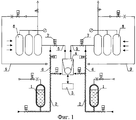
Принципиальная схема предлагаемого устройства показана на фиг.1, где:A schematic diagram of the proposed device is shown in figure 1, where:
1. Теплоизолированные расходные емкости.1. Thermally insulated consumables.
2. Магистральные трубопроводы подачи криогенного компонента в энергоустановку и накопительные емкости.2. The main pipelines for supplying the cryogenic component to the power plant and storage tanks.
3. Система управления и контроля.3. Management and control system.
4. Испытываемая энергоустановка.4. Tested power plant.
5. Магистральные трубопроводы подачи компонента в накопительные емкости после «захолаживания» энергоустановки.5. The main pipelines for supplying the component to the storage tanks after “cooling” the power plant.
6. Магистральные трубопроводы подачи остатков компонента в накопительные емкости.6. Main pipelines for supplying component residues to storage tanks.
7. Клапаны.7. Valves.
8. Не теплоизолированная накопительная емкость высокого давления.8. Non-insulated high pressure storage tank.
9. Магистральные трубопроводы подачи газифицированного компонента в энергоустановку.9. The main pipelines for supplying the gasified component to the power plant.
Стенд для испытаний энергоустановок с криогенными компонентами топлива включает систему подачи топлива, содержащую теплоизолированные расходные емкости 1, магистральные трубопроводы подачи криогенного компонента в энергоустановку и накопительные емкости 2, систему управления процессом испытаний и контроля параметров 3. Теплоизолированные расходные емкости 1 соединены магистральными трубопроводами подачи криогенного компонента в энергоустановку и накопительные емкости 2 с испытываемой энергоустановкой 4.The test bench for power plants with cryogenic fuel components includes a fuel supply system containing thermally insulated consumables 1, main pipelines for supplying a cryogenic component to a power plant and
Кроме того, энергоустановка 4 соединена магистральными трубопроводами 5 подачи компонента в накопительные емкости после «захолаживания» энергоустановки, содержащими клапана 7 с не теплоизолированной накопительной емкостью высокого давления 8.In addition, the power plant 4 is connected by
Подготовка работы стенда заключается в настройке циклограммы работы клапанов таким образом, чтобы осуществлялась возможность подачи в накопительные емкости остатков жидкого компонента после проведения испытаний и подачи этого компонента после его газификации на вход энергоустановки для проведения другого рода испытаний, причем энергия для газификации компонента берется с атмосферного воздуха, т.к. накопительная емкость высокого давления не теплоизолирована.Preparation of the stand’s work consists in adjusting the valve operation sequence diagram in such a way that it is possible to supply the residual liquid component to the storage tanks after testing and to supply this component after its gasification to the power plant inlet for another kind of testing, and the energy for gasification of the component is taken from atmospheric air because high pressure storage tank is not thermally insulated.
Предложенный стенд для испытаний энергоустановок с криогенными компонентами топлива работает следующим образом. Из расходных емкостей 1 криогенные топлива по магистральным трубопроводам 2 по команде из системы управления (циклограмме) 3 поступают в энергоустановку 4 для охлаждения конструкции турбонасосного агрегата до криогенной температуры в целях предотвращения кавитации его во время испытания. Газифицированные в трактах охлаждения после турбонасосного агрегата компоненты топлива после энергоустановки 4 по трубопроводу 5, с установленным в них агрегатами управления 7, поступают в накопительные емкости 8, проходят через них и их предварительно охлаждают для подготовки к более полному приему остатков топлива из расходных емкостей после испытаний. После проведения испытания (например: огневого) по магистральным трубопроводам 6 остатки криогенного топлива из расходных емкостей 1 подаются в накопительные емкости 8. В замкнутом объеме накопительных емкостей при закрытых агрегатах управления 7 компоненты топлива испаряются с одновременным повышением давления за счет подвода тепла из окружающей среды. При достижении заданного уровня давления, газифицированные компоненты топлива подаются по трубопроводу 9 к энергоустановке для проведения другого рода испытаний.The proposed test bench for power plants with cryogenic fuel components works as follows. From the supply tanks 1, cryogenic fuels through the
Таким образом, использование предлагаемого технического решения позволит более эффективно использовать компоненты топлива во время испытаний энергоустановок и повысить тем самым эффективность работы испытательного стенда.Thus, the use of the proposed technical solution will allow more efficient use of fuel components during testing of power plants and thereby increase the efficiency of the test bench.
Claims (1)
Priority Applications (1)
| Application Number | Priority Date | Filing Date | Title |
|---|---|---|---|
| RU2010141526/06A RU2445503C1 (en) | 2010-10-08 | 2010-10-08 | Test bench for testing power plants with fuel cryogenic components |
Applications Claiming Priority (1)
| Application Number | Priority Date | Filing Date | Title |
|---|---|---|---|
| RU2010141526/06A RU2445503C1 (en) | 2010-10-08 | 2010-10-08 | Test bench for testing power plants with fuel cryogenic components |
Publications (1)
| Publication Number | Publication Date |
|---|---|
| RU2445503C1 true RU2445503C1 (en) | 2012-03-20 |
Family
ID=46030193
Family Applications (1)
| Application Number | Title | Priority Date | Filing Date |
|---|---|---|---|
| RU2010141526/06A RU2445503C1 (en) | 2010-10-08 | 2010-10-08 | Test bench for testing power plants with fuel cryogenic components |
Country Status (1)
| Country | Link |
|---|---|
| RU (1) | RU2445503C1 (en) |
Cited By (7)
| Publication number | Priority date | Publication date | Assignee | Title |
|---|---|---|---|---|
| RU2553587C2 (en) * | 2012-06-07 | 2015-06-20 | Открытое акционерное общество "Информационные спутниковые системы" имени академика М.Ф. Решетнёва" | Method of heat and vacuum tests of thermocatalytic engines within spacecraft |
| RU2611119C1 (en) * | 2015-10-14 | 2017-02-21 | Акционерное общество "Конструкторское бюро химавтоматики" | Stand for power plants with used process gas accumulation testing |
| RU2631371C1 (en) * | 2016-05-23 | 2017-09-21 | Акционерное общество "Конструкторское бюро химавтоматики" | Power installation test method and test bench for its implementation |
| RU2704577C1 (en) * | 2019-03-05 | 2019-10-29 | Владимир Александрович Шишков | Method of preparing a cryogenic product for testing a power device |
| CN112576414A (en) * | 2020-12-02 | 2021-03-30 | 西安航天动力研究所 | Liquid rocket engine thrust chamber filling test device and method and simulation criterion |
| RU2770072C2 (en) * | 2021-06-09 | 2022-04-14 | Валентин Павлович Рылов | Test bench for the pumping system for powdered metal supply to the combustion chamber of a rocket engine |
| RU2859623C1 (en) * | 2025-12-02 | 2026-04-07 | Федеральное государственное автономное образовательное учреждение высшего образования "Южно-Уральский государственный университет (национальный исследовательский университет)" ФГАОУ ВО "ЮУрГУ (НИУ)" | Test bench for testing liquid rocket engines with electric pump system for supplying cryogenic propellant components |
Citations (3)
| Publication number | Priority date | Publication date | Assignee | Title |
|---|---|---|---|---|
| DE3838077C1 (en) * | 1988-11-10 | 1989-10-19 | Messerschmitt-Boelkow-Blohm Gmbh, 8012 Ottobrunn, De | Device for monitoring the temperature of rocket burners during operation |
| US5165229A (en) * | 1991-10-22 | 1992-11-24 | The United States Of America As Represented By The Administrator Of The National Aeronautics And Space Administration | Thruster sealing system and apparatus |
| RU2111373C1 (en) * | 1996-06-18 | 1998-05-20 | Конструкторское бюро химавтоматики | Liquid-propellant rocket engine test stand |
-
2010
- 2010-10-08 RU RU2010141526/06A patent/RU2445503C1/en not_active IP Right Cessation
Patent Citations (3)
| Publication number | Priority date | Publication date | Assignee | Title |
|---|---|---|---|---|
| DE3838077C1 (en) * | 1988-11-10 | 1989-10-19 | Messerschmitt-Boelkow-Blohm Gmbh, 8012 Ottobrunn, De | Device for monitoring the temperature of rocket burners during operation |
| US5165229A (en) * | 1991-10-22 | 1992-11-24 | The United States Of America As Represented By The Administrator Of The National Aeronautics And Space Administration | Thruster sealing system and apparatus |
| RU2111373C1 (en) * | 1996-06-18 | 1998-05-20 | Конструкторское бюро химавтоматики | Liquid-propellant rocket engine test stand |
Non-Patent Citations (1)
| Title |
|---|
| ЖУКОВСКИЙ А.Е. и др. Испытание жидкостных ракетных двигателей. - М.: Машиностроение, 1981, с.112-125, рис.44. * |
Cited By (8)
| Publication number | Priority date | Publication date | Assignee | Title |
|---|---|---|---|---|
| RU2553587C2 (en) * | 2012-06-07 | 2015-06-20 | Открытое акционерное общество "Информационные спутниковые системы" имени академика М.Ф. Решетнёва" | Method of heat and vacuum tests of thermocatalytic engines within spacecraft |
| RU2611119C1 (en) * | 2015-10-14 | 2017-02-21 | Акционерное общество "Конструкторское бюро химавтоматики" | Stand for power plants with used process gas accumulation testing |
| RU2631371C1 (en) * | 2016-05-23 | 2017-09-21 | Акционерное общество "Конструкторское бюро химавтоматики" | Power installation test method and test bench for its implementation |
| RU2704577C1 (en) * | 2019-03-05 | 2019-10-29 | Владимир Александрович Шишков | Method of preparing a cryogenic product for testing a power device |
| CN112576414A (en) * | 2020-12-02 | 2021-03-30 | 西安航天动力研究所 | Liquid rocket engine thrust chamber filling test device and method and simulation criterion |
| CN112576414B (en) * | 2020-12-02 | 2021-11-02 | 西安航天动力研究所 | Liquid rocket engine thrust chamber filling test device and method and simulation criterion |
| RU2770072C2 (en) * | 2021-06-09 | 2022-04-14 | Валентин Павлович Рылов | Test bench for the pumping system for powdered metal supply to the combustion chamber of a rocket engine |
| RU2859623C1 (en) * | 2025-12-02 | 2026-04-07 | Федеральное государственное автономное образовательное учреждение высшего образования "Южно-Уральский государственный университет (национальный исследовательский университет)" ФГАОУ ВО "ЮУрГУ (НИУ)" | Test bench for testing liquid rocket engines with electric pump system for supplying cryogenic propellant components |
Similar Documents
| Publication | Publication Date | Title |
|---|---|---|
| RU2445503C1 (en) | Test bench for testing power plants with fuel cryogenic components | |
| CA2831668C (en) | Apparatus and process for testing an industrial gas turbine engine and components thereof | |
| CA2914247C (en) | Process for testing a compressor or a combustor of a gas turbine engine using a large compressed air storage reservoir | |
| RU2427724C1 (en) | Cryogenic fuel supply system for engine feed | |
| RU2013121597A (en) | METHOD FOR SUPPLYING ADDITIONAL POWER BY AUXILIARY POWER UNIT AND APPROPRIATE DESIGN | |
| CN109611240B (en) | Mars detection attitude control engine rarefied incoming flow high-altitude simulation test system | |
| RU2016107834A (en) | DEVICE FOR CHARGING THE Rocket ENGINE FUEL TANKS | |
| Long et al. | Development of a facility to test an ejector ramjet at static conditions | |
| Matsutomi et al. | Facility development for testing of wave rotor combustion rig | |
| RU2486113C1 (en) | Space object cryogenic liquid-propellant engine starting system | |
| Morehead et al. | Vehicle-level oxygen/methane propulsion system hotfire demonstration at thermal vacuum conditions | |
| RU2012113824A (en) | ENGINE INSTALLATION OF SPACE AIRCRAFT (OPTIONS) AND METHOD OF ITS OPERATION | |
| RU2338083C1 (en) | Hybrid rocket engine | |
| RU2767405C2 (en) | Liquid oxygen rocket refueling system | |
| RU2423298C1 (en) | Rocket pod engine plant | |
| RU2611119C1 (en) | Stand for power plants with used process gas accumulation testing | |
| RU2466292C1 (en) | Liquid-propellant engine | |
| RU2009102138A (en) | METHOD OF EXPERIMENTAL CONFIRMATION OF AMPLITUDE-PHASE FREQUENCY CHARACTERISTICS OF LIQUID ROCKET ENGINES AND LIQUID ROCKET ENGINE (OPTIONS) | |
| Ellerbrock et al. | Liquid rocket engine test facility engineering challenges | |
| Morehead et al. | Vehicle-Level Oxygen/Methane Propulsion System Hotfire Testing at Thermal Vacuum Conditions | |
| RU2773694C1 (en) | Liquid rocket engine powered by cryogenic fuel | |
| RU2484287C1 (en) | Three-component liquid-propellant engine | |
| RU154857U1 (en) | GENERATOR | |
| Soejima et al. | Development of the fuel heating device for the component test of aerospace propulsion systems | |
| Robertson et al. | Portable test platform for student liquid rocket engine development |
Legal Events
| Date | Code | Title | Description |
|---|---|---|---|
| MM4A | The patent is invalid due to non-payment of fees |
Effective date: 20181009 |