RU2442688C2 - Worm element - Google Patents
Worm element Download PDFInfo
- Publication number
- RU2442688C2 RU2442688C2 RU2008142522/05A RU2008142522A RU2442688C2 RU 2442688 C2 RU2442688 C2 RU 2442688C2 RU 2008142522/05 A RU2008142522/05 A RU 2008142522/05A RU 2008142522 A RU2008142522 A RU 2008142522A RU 2442688 C2 RU2442688 C2 RU 2442688C2
- Authority
- RU
- Russia
- Prior art keywords
- screw
- kneading
- plasticizing
- width
- kneading blocks
- Prior art date
Links
Images


Classifications
-
- B—PERFORMING OPERATIONS; TRANSPORTING
- B29—WORKING OF PLASTICS; WORKING OF SUBSTANCES IN A PLASTIC STATE IN GENERAL
- B29B—PREPARATION OR PRETREATMENT OF THE MATERIAL TO BE SHAPED; MAKING GRANULES OR PREFORMS; RECOVERY OF PLASTICS OR OTHER CONSTITUENTS OF WASTE MATERIAL CONTAINING PLASTICS
- B29B7/00—Mixing; Kneading
- B29B7/30—Mixing; Kneading continuous, with mechanical mixing or kneading devices
- B29B7/34—Mixing; Kneading continuous, with mechanical mixing or kneading devices with movable mixing or kneading devices
- B29B7/38—Mixing; Kneading continuous, with mechanical mixing or kneading devices with movable mixing or kneading devices rotary
- B29B7/40—Mixing; Kneading continuous, with mechanical mixing or kneading devices with movable mixing or kneading devices rotary with single shaft
- B29B7/42—Mixing; Kneading continuous, with mechanical mixing or kneading devices with movable mixing or kneading devices rotary with single shaft with screw or helix
- B29B7/421—Mixing; Kneading continuous, with mechanical mixing or kneading devices with movable mixing or kneading devices rotary with single shaft with screw or helix with screw and additionally other mixing elements on the same shaft, e.g. paddles, discs, bearings, rotor blades of the Banbury type
-
- B—PERFORMING OPERATIONS; TRANSPORTING
- B29—WORKING OF PLASTICS; WORKING OF SUBSTANCES IN A PLASTIC STATE IN GENERAL
- B29C—SHAPING OR JOINING OF PLASTICS; SHAPING OF MATERIAL IN A PLASTIC STATE, NOT OTHERWISE PROVIDED FOR; AFTER-TREATMENT OF THE SHAPED PRODUCTS, e.g. REPAIRING
- B29C48/00—Extrusion moulding, i.e. expressing the moulding material through a die or nozzle which imparts the desired form; Apparatus therefor
- B29C48/25—Component parts, details or accessories; Auxiliary operations
- B29C48/256—Exchangeable extruder parts
- B29C48/2564—Screw parts
-
- B—PERFORMING OPERATIONS; TRANSPORTING
- B29—WORKING OF PLASTICS; WORKING OF SUBSTANCES IN A PLASTIC STATE IN GENERAL
- B29C—SHAPING OR JOINING OF PLASTICS; SHAPING OF MATERIAL IN A PLASTIC STATE, NOT OTHERWISE PROVIDED FOR; AFTER-TREATMENT OF THE SHAPED PRODUCTS, e.g. REPAIRING
- B29C48/00—Extrusion moulding, i.e. expressing the moulding material through a die or nozzle which imparts the desired form; Apparatus therefor
- B29C48/25—Component parts, details or accessories; Auxiliary operations
- B29C48/36—Means for plasticising or homogenising the moulding material or forcing it through the nozzle or die
- B29C48/50—Details of extruders
- B29C48/505—Screws
- B29C48/52—Screws with an outer diameter varying along the longitudinal axis, e.g. for obtaining different thread clearance
-
- B—PERFORMING OPERATIONS; TRANSPORTING
- B29—WORKING OF PLASTICS; WORKING OF SUBSTANCES IN A PLASTIC STATE IN GENERAL
- B29C—SHAPING OR JOINING OF PLASTICS; SHAPING OF MATERIAL IN A PLASTIC STATE, NOT OTHERWISE PROVIDED FOR; AFTER-TREATMENT OF THE SHAPED PRODUCTS, e.g. REPAIRING
- B29C48/00—Extrusion moulding, i.e. expressing the moulding material through a die or nozzle which imparts the desired form; Apparatus therefor
- B29C48/25—Component parts, details or accessories; Auxiliary operations
- B29C48/36—Means for plasticising or homogenising the moulding material or forcing it through the nozzle or die
- B29C48/50—Details of extruders
- B29C48/505—Screws
- B29C48/57—Screws provided with kneading disc-like elements, e.g. with oval-shaped elements
-
- B—PERFORMING OPERATIONS; TRANSPORTING
- B29—WORKING OF PLASTICS; WORKING OF SUBSTANCES IN A PLASTIC STATE IN GENERAL
- B29C—SHAPING OR JOINING OF PLASTICS; SHAPING OF MATERIAL IN A PLASTIC STATE, NOT OTHERWISE PROVIDED FOR; AFTER-TREATMENT OF THE SHAPED PRODUCTS, e.g. REPAIRING
- B29C48/00—Extrusion moulding, i.e. expressing the moulding material through a die or nozzle which imparts the desired form; Apparatus therefor
- B29C48/03—Extrusion moulding, i.e. expressing the moulding material through a die or nozzle which imparts the desired form; Apparatus therefor characterised by the shape of the extruded material at extrusion
Abstract
Description
ОписаниеDescription
Изобретение касается червячного элемента согласно ограничительной части пункта 1 формулы изобретения.The invention relates to a worm element according to the restrictive part of
При подготовке пластмасс в блоке пластификациии, как это происходит в экструдерах или машинах литья из пластмасс под давлением, используются разнообразные технологии. Одной из этих технологий является компаундирование, то есть подмешивание заполнителей или усиливающих материалов, ввода красок или пигментов, смешивание различных материалов, например полимерных материалов или эластомеров, реактивные технологии или т.п. Для всех технологий общим является то, что они осуществляются с помощью экструдера с одним или несколькими валами, которые содержат шнеки, вращающиеся в одном или противоположных направлениях. С помощью шнеков в материал вводится режущая энергия для расплавления пластического материала. Шнеки содержат так называемые червячные элементы, которые зачастую выполнены многозаходными.In the preparation of plastics in a plasticizing unit, as is the case in extruders or plastic injection machines, a variety of technologies are used. One of these technologies is compounding, that is, mixing aggregates or reinforcing materials, introducing paints or pigments, mixing various materials, for example polymeric materials or elastomers, reactive technologies or the like. Common to all technologies is that they are carried out using an extruder with one or more shafts that contain screws rotating in one or opposite directions. Using screws, cutting energy is introduced into the material to melt the plastic material. The augers contain the so-called worm elements, which are often multi-start.
Специальный червячный элемент представляет собой так называемый пластикационный элемент, получивший в литературе также наименование месильного блока. Такой месильный блок состоит из выполненных в форме спирали шнековых элементов или нескольких, расположенных друг за другом в направлении технологической линии месильных блоков, обладающих определенными геометрическими свойствами. В случае известных пластикационных элементов геометрическая форма месильных блоков одинакова, в частности применительно к их ширине и их внутреннему и внешнему диаметрам, и выбирается в зависимости от размера блока пластификации, то есть блока пластификации экструдера или машины литья под давлением.A special worm element is a so-called plasticizing element, which has also received the name of a kneading block in the literature. Such a kneading unit consists of helical elements made in the form of a spiral or several, located one after the other in the direction of the technological line of the kneading blocks, which have certain geometric properties. In the case of known plasticizing elements, the geometric shape of the kneading blocks is the same, in particular with respect to their width and their inner and outer diameters, and is selected depending on the size of the plasticizing block, i.e. the plasticizing block of the extruder or injection molding machine.
Диссипация прилагаемой с помощью привода через редуктор и вал шнека механической энергии определяется наряду, например, с зависимостью теплосодержания подлежащей переработке пластмассы, типом применяющейся конструкции шнеков. Тип использующейся конструкции шнеков называется также конфигурацией. Конфигурация варьируется, например, по типу и количеству месильных блоков и прочих элементов шнеков.The dissipation of the mechanical energy applied by means of the drive through the gearbox and the screw shaft is determined, for example, with the dependence of the heat content of the plastic to be processed, the type of screw construction used. The type of screw design used is also called configuration. The configuration varies, for example, in the type and number of kneading blocks and other screw elements.
Прежде всего достигается главное преобразование энергии в зависимости от геометрии шнековых элементов непосредственно перед или над первым или первыми пластикационными элементами. Это главное преобразование энергии осуществляется посредством среза. При этом в первую очередь определяющими являются число оборотов шнека и, следовательно, (угловая) скорость пластикационных элементов, зазоры между пластикационным элементом и корпусом экструдера, а также при использовании двухшнекового экструдера - между пластикационными элементами в незаполненных зонах и гребенчатая поверхность пластикационных элементов. На основании этих параметров можно соответствующим образом рассчитать скорость, а также напряжение среза. Напряжение среза определяет расплавление подлежащего пластификации материала. При расплавлении возникают максимальные механические нагрузки, воздействующие на червячный элемент шнека и его соединение вала со ступицей.First of all, the main energy conversion is achieved depending on the geometry of the screw elements immediately before or above the first or first plasticizing elements. This major energy conversion is carried out by means of a cut. In this case, the number of revolutions of the screw and, therefore, the (angular) speed of the plasticizing elements, the gaps between the plasticizing element and the extruder body, and also when using a twin-screw extruder, between the plasticizing elements in unfilled zones and the comb surface of the plasticizing elements, are primarily determining. Based on these parameters, the speed as well as the shear stress can be appropriately calculated. The shear stress determines the melting of the material to be plasticized. When melting, maximum mechanical loads occur, affecting the screw element of the screw and its connection of the shaft with the hub.
Такой пластикационный элемент известен из немецкой полезной модели 82 32 585.Such a plasticizing element is known from the German utility model 82 32 585.
Изображенный там червячный элемент содержит отдельные месильные блоки, которые могут быть по отдельности состыкованы в один пластикационный элемент. При этом месильные узлы имеют одну и ту же геометрическую форму.The worm element shown there contains separate kneading blocks, which can be individually joined into one plasticizing element. In this case, the kneading units have the same geometric shape.
В заявке DE 100 50 295 A1 описан экструдер с несколькими валами для подготовки и/или обработки снабженного наполнителем эластомера с, по меньшей мере, двумя валами, которые при рассмотрении в направлении транспортировки имеют зону заполнения, зону пластикации и зону диспергирования. При этом зона пластикации, равно как и зона диспергирования, могут содержать пластикационные диски, максимальный диаметр которых увеличивается или уменьшается в технологическом направлении.DE 100 50 295 A1 describes an extruder with several shafts for the preparation and / or processing of a filler-filled elastomer with at least two shafts which, when viewed in the direction of transport, have a filling zone, a plasticizing zone and a dispersion zone. In this case, the plasticization zone, as well as the dispersion zone, may contain plasticizing disks, the maximum diameter of which increases or decreases in the technological direction.
В реферате заявки JP 20004202871 описан пластикационный шнек, который содержит между двумя участками транспортировки один пластикационный участок, пластикационные диски которого имеют непрерывно возрастающий в направлении транспортировки диаметр.In the abstract of the application JP 20004202871, a plasticizing screw is described, which contains one plasticizing section between two transportation sections, the plasticizing disks of which have a continuously increasing diameter in the transportation direction.
Заявка DE 199 60 917 A1 касается двухшнекового экструдера с определенными элементами шнека, в котором при хорошем дисперсивном смешивающем эффекте возникает минимально возможное диссипативное повышение температуры. В описании лишь в общем указывается на то, что червячные элементы могут иметь непрерывный угол подъема (проворачивание), или же также могут быть предусмотрены диски перемененной ширины, шаг которых бесконечен (без проворачивания) или которые расположены с угловым смещением (так называемые месильные блоки).DE 199 60 917 A1 relates to a twin-screw extruder with certain screw elements, in which, with good dispersive mixing effect, the smallest possible dissipative temperature increase occurs. The description only generally indicates that the worm elements can have a continuous angle of elevation (turning), or disks of variable width can also be provided, the pitch of which is infinite (without turning) or which are located with an angular displacement (the so-called kneading blocks) .
Задачей настоящего изобретения является создание червячного элемента первоначально названного типа, при котором обеспечивается хорошая пластификация подлежащего обработке материала при сниженной механической нагрузке на червячные элементы.The present invention is the creation of a worm element of the originally named type, which provides good plasticization of the material to be processed with reduced mechanical load on the worm elements.
В соответствии с изобретением поставленная задача решается признаками пункта 1 формулы изобретения.In accordance with the invention, the task is solved by the characteristics of
Согласно ему рассматриваемый червячный элемент выполнен и модифицирован таким образом, что, по меньшей мере, два последовательно расположенных пластикационных блока имеют различную геометрическую форму, причем ширина месильных блоков возрастает в направлении технологического процесса.According to it, the considered worm element is made and modified in such a way that at least two plasticizing blocks arranged in series have different geometric shapes, and the width of the kneading blocks increases in the direction of the technological process.
Таким образом, ширина, по меньшей мере, двух месильных блоков может быть различной. В результате этого возможно было бы влиять на зазор среза исходя из того, что происходит изменение поверхности среза. Так же как и при еще описанном ниже изменении диаметра месильного блока, это могло бы осуществляться внутри одного или нескольких следующих друг за другом червячных элементов шнека. Месильные блоки или части шнека имеют различную ширину на протяжении ширины червячного элемента. К тому же месильные блоки или частичные отрезки шнека также могли бы иметь различный диаметр на всей своей протяженности. Червячные элементы шнека могут не зависеть от количества элементов в шнеке. Тем самым переменность ширины ребер дисков может распространяться на несколько червячных элементов шнека. Таким образом, червячные элементы шнека могут быть независимыми от длины.Thus, the width of at least two kneading blocks may be different. As a result of this, it would be possible to influence the cut gap based on the fact that a change in the cut surface occurs. As with the variation in the diameter of the kneading unit as described below, this could be carried out inside one or more successive screw elements of the screw. Kneading blocks or parts of the screw have different widths along the width of the worm element. In addition, kneading blocks or partial segments of the screw could also have different diameters over their entire length. The screw elements of the screw may not depend on the number of elements in the screw. Thus, the variability of the width of the ribs of the disks can extend to several worm elements of the screw. Thus, the screw elements of the screw can be independent of length.
В общей сложности ширина месильных блоков возрастает в направлении технологического процесса. В результате этого происходило бы увеличение среза подлежащего пластификации материала в направлении технологического процесса. В качестве направления технологического процесса определяется таким образом направление блока пластификации, в котором по существу происходит транспортировка подлежащего пластификации и/или пластифицированного материала.In total, the width of the kneading blocks increases in the direction of the process. As a result of this, there would be an increase in the cut of the material to be plasticized in the direction of the technological process. As the direction of the technological process, the direction of the plasticization unit is thus determined, in which the plasticization and / or plasticized material to be transported essentially occurs.
Последовательность переменности ширины месильных блоков не должна, однако, постоянно возрастать и может быть также частично постоянной.The sequence of variability of the width of the kneading blocks should not, however, constantly increase and may also be partially constant.
В целом было установлено, что для достижения хорошей пластификации при пониженной механической нагрузке на червячный элемент шнека возможно отклонение от известной формы той же геометрической формы месильных блоков. При выборе различных геометрических форм месильных блоков, а именно различных значений ширины, обеспечивается возможность контроля инициации резки и механической нагрузки, а также оптимизации соответствующей операции.In general, it was found that in order to achieve good plasticization with reduced mechanical load on the screw element of the screw, a deviation from the known shape of the same geometric shape of the kneading blocks is possible. When choosing various geometric shapes of kneading blocks, namely different widths, it is possible to control the initiation of cutting and mechanical loading, as well as optimize the corresponding operation.
Использование соответствующих изобретению червячных элементов шнека возможно применительно к большому количеству блоков пластификации и самым различным технологиям. Представляется возможным использование соответствующих изобретению пластикационных элементов при содержащих два и более валов, вращающихся в одинаковом или противоположных направлениях, блоках пластификации. Также возможно выполнение червячных элементов шнека одно- или многозаходными и состоящими из спиралевидных участков или интегрально выполненных или свободно соединенных между собой месильных блоков. Месильные блоки выбираются в зависимости от размера блока пластификации и конкретной технологической задачи. Соответствующее изобретению выполнение червячного элемента шнека в соответствии с этим не зависит от размера машины и диаметра элемента шнека. Кроме того, червячные элементы шнека не зависят от типа соединения вала и ступицы, а также числа заходов червячного элемента шнека. Кроме того, червячные элементы шнека могут использоваться при любом типе подлежащего пластификации материала и не зависят от соотношения Da/Di, а также направления вращения шнека.The use of screw elements of the screw according to the invention is possible in relation to a large number of plasticization blocks and a wide variety of technologies. It seems possible to use plasticizing elements according to the invention with two or more shafts, plasticization blocks rotating in the same or opposite directions. It is also possible that the worm elements of the screw can be made single or multiple and consisting of spiral sections or integrally made or freely kneading blocks. Kneading blocks are selected depending on the size of the plasticization block and the specific technological task. According to the invention, the implementation of the screw element of the screw in accordance with this does not depend on the size of the machine and the diameter of the screw element. In addition, the screw elements of the screw do not depend on the type of connection of the shaft and the hub, as well as the number of visits of the screw element of the screw. In addition, the screw elements of the screw can be used for any type of material to be plasticized and do not depend on the ratio D a / D i , as well as the direction of rotation of the screw.
В особо предпочтительном случае геометрическая форма месильных блоков выбирается таким образом, что может быть достигнуто непрерывное усиление резки подлежащего пластификации материала. Это могло бы создать особое преимущество, выраженное в том, что начало резки реализуется не массивно и внезапно, а может осуществляться плавно, например, с постоянным нарастанием. В механическом смысле такое выполнение было бы особенно предпочтительным, так как нагрузка на элемент прикладывается также скорее с возрастающим «набуханием» на протяжении более длинного участка, чем локально брахиально в узкоограниченной зоне.In a particularly preferred case, the geometric shape of the kneading blocks is selected in such a way that continuous reinforcement of cutting of the material to be plasticized can be achieved. This could create a special advantage, expressed in that the beginning of cutting is not realized massive and sudden, but can be carried out smoothly, for example, with a constant increase. In the mechanical sense, such an implementation would be particularly preferable, since the load on the element is also applied more likely with increasing "swelling" over a longer section than locally brachially in a narrowly bounded zone.
Как уже упоминалось, диаметры, по меньшей мере, двух месильных блоков также могут быть различными. За счет этого зазор среза, который образуется между месильными блоками и корпусом экструдера, может выполняться меньшим или большим в направлении технологического процесса. При предпочтительном выполнении было бы возможно увеличение диаметров отдельных месильных блоков или участков в направлении процесса. Месильные блоки, равно как и расположенные один за другим пластикационные элементы, могли бы при этом иметь различные диаметры по всей длине.As already mentioned, the diameters of at least two kneading blocks can also be different. Due to this, the shear gap that is formed between the kneading blocks and the extruder body can be made smaller or larger in the direction of the process. With a preferred embodiment, it would be possible to increase the diameters of the individual kneading blocks or sections in the direction of the process. Kneading blocks, as well as plasticizing elements located one after the other, could have different diameters along the entire length.
Последовательность диаметров не должна, однако, постоянно принудительно возрастать и может также частично оставаться неизменной или уменьшаться. В зависимости от технологической задачи, однако, представляются возможными все возможные вариации диаметра. Переменность диаметра при этом может распространяться на различные червячные элементы шнека.The sequence of diameters should not, however, constantly forcibly increase and may also partially remain unchanged or decrease. Depending on the technological task, however, all possible variations of the diameter seem possible. In this case, the variability of the diameter can extend to various screw elements of the screw.
При возрастании диаметра месильных блоков в направлении процесса механическая нагрузка прикладывалась бы к элементу с возрастающим «набуханием» на протяжении более длинного участка. Очередность переменности диаметра пластикационных узлов не должна, однако, постоянно возрастать, а может быть также частично неизменной или уменьшающейся.With an increase in the diameter of the kneading blocks in the direction of the process, a mechanical load would be applied to the element with increasing “swelling” over a longer section. The sequence of variability of the diameter of the plasticizing nodes should not, however, constantly increase, but may also be partially constant or decreasing.
Переменность геометрической формы оказывает таким образом прямое влияние на развитие скорости среза и напряжения среза перед червячным элементом и в червячном элементе шнека, а также на развитие механической нагрузки на элементы. Далее, соотношение Da/Di месильных блоков при соответствующем изобретению червячном элементе шнека может быть неизменным или, однако, варьироваться.The variability of the geometric shape thus has a direct effect on the development of shear speed and shear stress in front of the screw element and in the screw element of the screw, as well as on the development of the mechanical load on the elements. Further, the ratio D a / D i of the kneading blocks for the screw screw element of the screw according to the invention can be unchanged or, however, vary.
В случае предпочтительного выполнения диаметр и ширина, по меньшей мере, двух месильных блоков могли бы быть различными. За счет этого была бы достигнута возможность особо большой переменности зазора среза. Выполненный таким образом червячный элемент шнека мог бы также особо удачно согласовываться с различными технологическими задачами.In a preferred embodiment, the diameter and width of at least two kneading blocks could be different. Due to this, the possibility of a particularly large variability of the cut gap would be achieved. The worm element of the screw made in this way could also be particularly well coordinated with various technological tasks.
В рамках особо хорошего начала резки и применительно ко взвешенной нагрузке на режущий элемент было бы возможным увеличение как диаметра, так и ширины месильных блоков в направлении процесса.In the context of a particularly good start to cutting and in relation to a weighted load on the cutting element, it would be possible to increase both the diameter and the width of the kneading blocks in the process direction.
Существуют различные возможности реализации предпочтительным образом и дальнейшей модификации заявленного технического решения. Для этого следует сослаться, с одной стороны, на зависимые от п.1 пункта формулы изобретения и, с другой стороны, на последующее пояснение предпочтительных примеров выполнения соответствующего изобретению червячного элемента шнека с привлечением чертежа. В сочетании с пояснениями предпочтительных примеров выполнения соответствующего изобретению элемента шнека на основании чертежа, также в общем поясняются предпочтительные формы выполнения и модификации технического решения.There are various possibilities for implementing the preferred manner and further modifying the claimed technical solution. For this, it is necessary to refer, on the one hand, to the claims dependent on
На фигурах показывают:The figures show:
фиг.1 - в схематической горизонтальной проекции пример выполнения червячного элемента шнека с переменным диаметром;figure 1 is a schematic horizontal projection of an example of a worm element of a screw with a variable diameter;
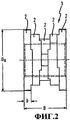
фиг.2 - в схематическом виде сбоку изображенный на фиг.1 пример выполнения червячного элемента шнека с переменным диаметром;figure 2 is a schematic side view shown in figure 1 an example of the execution of the worm element of the screw with a variable diameter;
фиг.3 - в схематической горизонтальной проекции пример выполнения соответствующего изобретению червячного элемента шнека с переменной шириной месильного блока; иfigure 3 - in a schematic horizontal projection, an example of implementation of the screw element of the screw according to the invention with a variable width of the kneading block; and
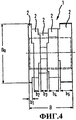
фиг.4 - в схематическом виде сбоку показанный на фиг.3 пример выполнения соответствующего изобретению червячного элемента шнека с переменной шириной месильного блока.FIG. 4 is a schematic side view of FIG. 3 illustrating an example embodiment of a screw element of a screw with a variable width of a kneading block according to the invention.
В случае изображенных примеров выполнения речь идет при червячном элементе шнека о пластикационном элементе 1, который используется в неизображенном узле пластификации с также неизображенным валом шнека.In the case of the illustrated embodiments, we are talking about the worm element of the screw about the
Пластикационный элемент 1 составлен из месильных блоков 2, которые в случае этого примера исполнения жестко соединены между собой. Месильные блоки 2 расположены на общей оси. С этой целью месильные блоки 2 содержат зубчатую нарезку, которая может входить в зацепление с зубчатой нарезкой на валу шнека, и тем самым пластикационный элемент закреплен на валу шнека по существу без возможности проворачивания. Месильные блоки 2 имеют геометрическую форму, которая определена двумя диаметрами Di и Da, то есть диаметрами D1 или D2, D3 или D4.The
При этом оба расположенных один за другим месильных блока 2 имеют различную геометрическую форму. В случае изображенного на фиг.1 пластикационного элемента происходит увеличение внешнего диаметра Da в направлении процесса. Это означает, что месильный блок 2 с наименьшим диаметром D1 в случае этого примера выполнения расположен ближе всего в направлении зоны запитывания, а пластикационный диск 2 с внешним диаметром D4 расположен дальше всех в направлении зоны выгрузки. В изображенном в данном случае примере выполнения диаметр D4 таким образом больше диаметра D3, а диаметр D3 больше диаметра D2. Диаметр D1, в свою очередь, меньше диаметра D2, то есть D1<D2<D3<D4. Внутренний диаметр Di пластикационного элемента 1 при этом остается неизменным. При конкретном выполнении представляется возможным варьирование внутреннего диаметра D1 соответственно диаметру D2 или иначе, чем внешний диаметр D2.In this case, both kneading
Фиг.2 показывает в схематической форме изображенный на фиг.1 пластикационный элемент 1. Пластикационный элемент 1 этого примера выполнения имеет общую ширину В. Месильные блоки 2 имеют в свою очередь ширину b.FIG. 2 shows in a schematic form the
Фиг.3 показывает соответствующий изобретению пластикационный элемент с переменной шириной поперечного ребра, то есть это означает, что месильные блоки 2 имеют различные значения ширины b.Figure 3 shows a plasticizing element according to the invention with a variable width of the transverse rib, that is, this means that the kneading blocks 2 have different values of width b.
В случае этого примера выполнения соотношение Da/Di диаметров является неизменным. Далее следует обратить внимание на то, что внешний диаметр Da также является неизменным. Ширина b месильных блоков 2 возрастает в направлении процесса. Тем самым повышается резка материала по ширине В пластикационного элемента 1. В случае этого конкретного примера выполнения ширина b1 месильного блока 2, который в этом пластикационном элементе 1 располагается ближе всех в направлении зоны запитывания, меньше ширины b2. Ширина b2 в свою очередь меньше ширины b3. Ширина b4 следующего месильного блока 2 в свою очередь больше ширины b3 предшествующего месильного блока 2. Далее, ширина b5 месильного блока 2, который расположен относительно этого месильного блока 2 дальше всех в направлении зоны выгрузки, больше ширины b4, то есть b1<b2<b3<b4.In the case of this embodiment, the ratio D a / D i of the diameters is unchanged. Next, it should be noted that the outer diameter D a is also unchanged. The width b of the kneading blocks 2 increases in the direction of the process. This increases the cutting of the material across the width B of the
В отношении дальнейших деталей во избежание повторений дается ссылка на общее описание.For further details, a general description is given to avoid repetition.
В конечном итоге следует четко указать на то, что описанные выше примеры выполнения служат исключительно для пояснения заявленного технического решения, которое, однако, не ограничивается этими примерами выполнения.In the end, it should be clearly indicated that the examples described above serve solely to clarify the claimed technical solution, which, however, is not limited to these examples.
Перечень ссылочных обозначений:List of reference designations:
1 Пластикационный элемент1 Plastic element
2 Месильный блок2 Kneading block
DA,D1, D2, D3, D4 Внешние диаметрыD A , D 1 , D 2 , D 3 , D 4 Outer diameters
Di Внутренний диаметр месильного блокаD i The inner diameter of the kneading unit
b Ширина месильного блокаb Kneading unit width
В Ширина пластикационного элементаB Width of plasticizing element
Claims (3)
Applications Claiming Priority (2)
| Application Number | Priority Date | Filing Date | Title |
|---|---|---|---|
| DE102006014692A DE102006014692B3 (en) | 2006-03-28 | 2006-03-28 | Kneading assembly for plastic and rubber compounds has two or more discrete kneading stations on a single helical spindle |
| DE102006014692.1 | 2006-03-28 |
Publications (2)
| Publication Number | Publication Date |
|---|---|
| RU2008142522A RU2008142522A (en) | 2010-05-10 |
| RU2442688C2 true RU2442688C2 (en) | 2012-02-20 |
Family
ID=38268426
Family Applications (1)
| Application Number | Title | Priority Date | Filing Date |
|---|---|---|---|
| RU2008142522/05A RU2442688C2 (en) | 2006-03-28 | 2007-03-21 | Worm element |
Country Status (9)
| Country | Link |
|---|---|
| US (1) | US20090016147A1 (en) |
| EP (1) | EP2001650B1 (en) |
| JP (1) | JP5130285B2 (en) |
| CN (1) | CN101400500B (en) |
| CA (1) | CA2644925C (en) |
| DE (1) | DE102006014692B3 (en) |
| RU (1) | RU2442688C2 (en) |
| TW (1) | TWI432309B (en) |
| WO (1) | WO2007112861A1 (en) |
Cited By (1)
| Publication number | Priority date | Publication date | Assignee | Title |
|---|---|---|---|---|
| RU2675903C2 (en) * | 2014-04-22 | 2018-12-25 | Кохеи САВА | Mixing device |
Families Citing this family (4)
| Publication number | Priority date | Publication date | Assignee | Title |
|---|---|---|---|---|
| JP4834653B2 (en) * | 2007-12-19 | 2011-12-14 | 株式会社神戸製鋼所 | Kneading screw and extruder |
| DE102013110671B4 (en) | 2013-09-26 | 2018-05-24 | Kraussmaffei Berstorff Gmbh | Wear body for receiving a twin screw for the extrusion of meltable material |
| EP3311975A1 (en) * | 2016-10-18 | 2018-04-25 | Reifenhäuser GmbH & Co. KG Maschinenfabrik | Screw for use in an extruder and extruder |
| AU2018275182A1 (en) | 2017-06-01 | 2019-07-25 | Wenger Manufacturing Inc. | High specific mechanical energy extrusion screw assembly |
Family Cites Families (37)
| Publication number | Priority date | Publication date | Assignee | Title |
|---|---|---|---|---|
| US1101142A (en) * | 1912-03-28 | 1914-06-23 | Max Mueller | Auger brick-machine. |
| US2453088A (en) * | 1945-12-26 | 1948-11-02 | Dow Chemical Co | Mixing torpedo for plastics extruders |
| US2607077A (en) * | 1951-06-28 | 1952-08-19 | Dow Chemical Co | Mixing torpedo for plastics extruders |
| US3146493A (en) * | 1960-07-25 | 1964-09-01 | Bergwerksgesellschaft Hibernia | Process and apparatus for the production of polyolefine granulates |
| DE1502335B2 (en) * | 1965-02-13 | 1971-10-21 | Werner & Pfleiderer, 7000 Stuttgart | SCREW EXTRUSION PRESS FOR THE PROCESSING OF PLASTIC |
| DE1679884B2 (en) * | 1967-12-16 | 1971-08-26 | Werner & Pfleiderer | MULTIPLE SHAFT CONTINUOUSLY WORKING MIXER AND MIXING MACHINE FOR PLASTIC MACHINE |
| US4015833A (en) * | 1975-10-03 | 1977-04-05 | The B. F. Goodrich Company | Extruder screw |
| US4099897A (en) * | 1975-11-04 | 1978-07-11 | Hitachi Cable, Ltd. | Apparatus for producing foamed plastic insulated wires |
| DE3026842C2 (en) * | 1980-07-16 | 1984-02-16 | Hermann Berstorff Maschinenbau Gmbh, 3000 Hannover | Twin screw venting extruder for thermoplastic materials |
| US4408887A (en) * | 1981-12-07 | 1983-10-11 | Kishihiro Yamaoka | Continuous kneader |
| DE8232585U1 (en) * | 1982-11-20 | 1983-06-23 | Leistritz Maschinenfabrik Paul Leistritz GmbH, 8500 Nürnberg | KNEADING BLOCK FOR SIMULTANEOUS SCREW PRESSES |
| US4663103A (en) * | 1983-08-09 | 1987-05-05 | Collins & Aikman Corporation | Apparatus and method of extrusion |
| DE3412258A1 (en) * | 1984-04-02 | 1985-10-10 | Werner & Pfleiderer, 7000 Stuttgart | SINGLE-TWIST DOUBLE-SCREW MIXER WITH WHEEL DISC |
| DE3668577D1 (en) * | 1985-08-16 | 1990-03-08 | Idemitsu Petrochemical Co | SNAIL FOR PROCESSING THERMOPLASTIC PLASTIC. |
| AU620380B2 (en) * | 1988-03-18 | 1992-02-20 | Denso Corporation | Fiber-reinforced polymer composition and method of producing same |
| DE3841728C1 (en) * | 1988-12-10 | 1990-03-01 | Hermann Berstorff Maschinenbau Gmbh, 3000 Hannover, De | |
| DE3841729C1 (en) * | 1988-12-10 | 1990-03-01 | Hermann Berstorff Maschinenbau Gmbh, 3000 Hannover, De | |
| JPH0677679B2 (en) * | 1991-07-29 | 1994-10-05 | ビーエイチ工業有限会社 | Continuous kneading machine |
| US5486366A (en) * | 1993-09-24 | 1996-01-23 | Wm. Wrigley Jr. Company | Continuous chewing gum base manufacturing process using a mixing-restriction element |
| JP2909577B2 (en) * | 1993-10-29 | 1999-06-23 | トヨタ自動車株式会社 | Resin waste material recycling method and apparatus |
| JP3472391B2 (en) * | 1995-07-19 | 2003-12-02 | 東芝機械株式会社 | Twin screw extruder and extrusion method using the twin screw extruder |
| US6254266B1 (en) * | 1998-05-22 | 2001-07-03 | Robert A. Barr | Floating ring mixer for extruder |
| SE9802350D0 (en) * | 1998-07-01 | 1998-07-01 | Borealis As | Mixing device |
| JP2000037764A (en) * | 1998-07-23 | 2000-02-08 | Asahi Chem Ind Co Ltd | Extrusion machine and method using the machine |
| US6241375B1 (en) * | 1998-08-01 | 2001-06-05 | Peter Wang | Shear ring screw |
| US6234659B1 (en) * | 1998-09-25 | 2001-05-22 | Hpm Corporation | Surge suppressor for vented injection molding machine screw |
| US6132076A (en) * | 1998-12-09 | 2000-10-17 | General Electric Company | Single extruder screw for efficient blending of miscible and immiscible polymeric materials |
| DE19860256A1 (en) * | 1998-12-24 | 2000-06-29 | Krupp Werner & Pfleiderer Gmbh | Two-shaft extruder |
| JP2000296517A (en) * | 1999-04-15 | 2000-10-24 | Japan Steel Works Ltd:The | Kneading screw piece body |
| DE19950917A1 (en) * | 1999-10-21 | 2001-04-26 | Degussa | Twin screw extruder with new screw elements |
| DE10050295A1 (en) * | 2000-10-10 | 2002-04-11 | Buehler Ag | Multi-shaft extruder for processing rubber compounds with fillers and additives has a specified gap between the shaft kneading blocks and barrel wall |
| US7049361B2 (en) * | 2001-03-14 | 2006-05-23 | Sumitomo Chemical Company, Limited | Polyolefin series resinfilm, composition for preparing the same, process for preparing the composition for preparing the same, and apparatus for preparing the same |
| DE10233213B4 (en) * | 2002-07-22 | 2004-09-09 | 3+Extruder Gmbh | extruder |
| JP2004202871A (en) * | 2002-12-25 | 2004-07-22 | Japan Steel Works Ltd:The | Screw for kneading extruder |
| DE102004019430A1 (en) * | 2004-04-19 | 2005-11-03 | Basf Ag | Preparation of molding materials comprises preparing rubber in emulsion, isolating the rubber, mixing the obtained rubber with organic solvent and thermoplastic matrix, removing the solvent and regenerating the product |
| US7246936B2 (en) * | 2004-06-04 | 2007-07-24 | Certainteed Corp. | Dynamic mixer screw tip |
| US7527493B1 (en) * | 2007-11-01 | 2009-05-05 | Md Plastics Incorporated | Precise control non-return valve |
-
2006
- 2006-03-28 DE DE102006014692A patent/DE102006014692B3/en not_active Expired - Fee Related
-
2007
- 2007-02-16 TW TW096105903A patent/TWI432309B/en active
- 2007-03-21 JP JP2009501912A patent/JP5130285B2/en active Active
- 2007-03-21 CN CN2007800087319A patent/CN101400500B/en active Active
- 2007-03-21 CA CA2644925A patent/CA2644925C/en not_active Expired - Fee Related
- 2007-03-21 EP EP07711985.7A patent/EP2001650B1/en active Active
- 2007-03-21 WO PCT/EP2007/002482 patent/WO2007112861A1/en active Application Filing
- 2007-03-21 RU RU2008142522/05A patent/RU2442688C2/en not_active IP Right Cessation
-
2008
- 2008-09-16 US US12/211,410 patent/US20090016147A1/en not_active Abandoned
Cited By (1)
| Publication number | Priority date | Publication date | Assignee | Title |
|---|---|---|---|---|
| RU2675903C2 (en) * | 2014-04-22 | 2018-12-25 | Кохеи САВА | Mixing device |
Also Published As
| Publication number | Publication date |
|---|---|
| US20090016147A1 (en) | 2009-01-15 |
| TW200800569A (en) | 2008-01-01 |
| CN101400500A (en) | 2009-04-01 |
| WO2007112861A1 (en) | 2007-10-11 |
| EP2001650A1 (en) | 2008-12-17 |
| RU2008142522A (en) | 2010-05-10 |
| CA2644925A1 (en) | 2007-10-11 |
| DE102006014692B3 (en) | 2007-08-02 |
| JP5130285B2 (en) | 2013-01-30 |
| CA2644925C (en) | 2013-10-29 |
| CN101400500B (en) | 2013-08-28 |
| TWI432309B (en) | 2014-04-01 |
| EP2001650B1 (en) | 2016-03-16 |
| JP2009531199A (en) | 2009-09-03 |
Similar Documents
| Publication | Publication Date | Title |
|---|---|---|
| JP4445478B2 (en) | Plasticizing and kneading extruder for plastic raw materials | |
| KR100190725B1 (en) | Continuous mixing of elastomeric compounds | |
| JP4205127B2 (en) | Kneading screw, twin screw extruder, and assembling method of kneading screw | |
| RU2442688C2 (en) | Worm element | |
| US9463581B2 (en) | Kneading degree adjusting mechanism, extruder, continuous mixer, kneading degree adjusting method, and kneading method | |
| JP5137613B2 (en) | Kneading disc segment and twin screw extruder | |
| JP7093681B2 (en) | Kneading method and kneaded product | |
| US8636497B2 (en) | Extruder screw for a screw extruder | |
| JP4555351B2 (en) | Kneading degree adjusting device, extruder, and continuous kneader | |
| KR102000491B1 (en) | Extruder screw element | |
| WO2006022839A2 (en) | Apparatus for plasticating thermoplastic resin including polypropylene | |
| US20080181051A1 (en) | Screw for extruder, bearing segment used in the same and twin screw extruder provided with screw for extruder | |
| US10576661B2 (en) | Material kneading apparatus and material kneading method | |
| CN202155160U (en) | Conical dual-rotor continuous mixing unit | |
| BG64085B1 (en) | Plasticizing screw | |
| RU2053122C1 (en) | Extruder for processing and production of rubber and thermoplastic plastic materials | |
| JP4834653B2 (en) | Kneading screw and extruder | |
| JP2009531199A5 (en) | ||
| CN210820794U (en) | Double-screw extruder | |
| JPH05220818A (en) | Single-spindle extruder | |
| JP2019043043A (en) | Screw and extruder | |
| KR20180120740A (en) | Screw extruder | |
| JP2006500257A5 (en) | ||
| US20040213077A1 (en) | Plastic screw | |
| JP5383092B2 (en) | Screw and molded product manufacturing method |
Legal Events
| Date | Code | Title | Description |
|---|---|---|---|
| MM4A | The patent is invalid due to non-payment of fees |
Effective date: 20150322 |