RU2442250C2 - The shield connected to the connector the shield connected to the connector applied to the field of telecommunications, the combination of the connector and at least one shield, the method of shielding of the connector - Google Patents
The shield connected to the connector the shield connected to the connector applied to the field of telecommunications, the combination of the connector and at least one shield, the method of shielding of the connector Download PDFInfo
- Publication number
- RU2442250C2 RU2442250C2 RU2010112250/07A RU2010112250A RU2442250C2 RU 2442250 C2 RU2442250 C2 RU 2442250C2 RU 2010112250/07 A RU2010112250/07 A RU 2010112250/07A RU 2010112250 A RU2010112250 A RU 2010112250A RU 2442250 C2 RU2442250 C2 RU 2442250C2
- Authority
- RU
- Russia
- Prior art keywords
- connector
- cable
- screen
- wires
- shielding
- Prior art date
Links
Images
Classifications
-
- H—ELECTRICITY
- H01—ELECTRIC ELEMENTS
- H01R—ELECTRICALLY-CONDUCTIVE CONNECTIONS; STRUCTURAL ASSOCIATIONS OF A PLURALITY OF MUTUALLY-INSULATED ELECTRICAL CONNECTING ELEMENTS; COUPLING DEVICES; CURRENT COLLECTORS
- H01R13/00—Details of coupling devices of the kinds covered by groups H01R12/70 or H01R24/00 - H01R33/00
- H01R13/46—Bases; Cases
- H01R13/502—Bases; Cases composed of different pieces
-
- H—ELECTRICITY
- H01—ELECTRIC ELEMENTS
- H01R—ELECTRICALLY-CONDUCTIVE CONNECTIONS; STRUCTURAL ASSOCIATIONS OF A PLURALITY OF MUTUALLY-INSULATED ELECTRICAL CONNECTING ELEMENTS; COUPLING DEVICES; CURRENT COLLECTORS
- H01R13/00—Details of coupling devices of the kinds covered by groups H01R12/70 or H01R24/00 - H01R33/00
- H01R13/648—Protective earth or shield arrangements on coupling devices, e.g. anti-static shielding
- H01R13/658—High frequency shielding arrangements, e.g. against EMI [Electro-Magnetic Interference] or EMP [Electro-Magnetic Pulse]
- H01R13/6591—Specific features or arrangements of connection of shield to conductive members
- H01R13/6592—Specific features or arrangements of connection of shield to conductive members the conductive member being a shielded cable
- H01R13/6593—Specific features or arrangements of connection of shield to conductive members the conductive member being a shielded cable the shield being composed of different pieces
-
- H—ELECTRICITY
- H01—ELECTRIC ELEMENTS
- H01R—ELECTRICALLY-CONDUCTIVE CONNECTIONS; STRUCTURAL ASSOCIATIONS OF A PLURALITY OF MUTUALLY-INSULATED ELECTRICAL CONNECTING ELEMENTS; COUPLING DEVICES; CURRENT COLLECTORS
- H01R24/00—Two-part coupling devices, or either of their cooperating parts, characterised by their overall structure
- H01R24/60—Contacts spaced along planar side wall transverse to longitudinal axis of engagement
- H01R24/62—Sliding engagements with one side only, e.g. modular jack coupling devices
- H01R24/64—Sliding engagements with one side only, e.g. modular jack coupling devices for high frequency, e.g. RJ 45
-
- H—ELECTRICITY
- H01—ELECTRIC ELEMENTS
- H01R—ELECTRICALLY-CONDUCTIVE CONNECTIONS; STRUCTURAL ASSOCIATIONS OF A PLURALITY OF MUTUALLY-INSULATED ELECTRICAL CONNECTING ELEMENTS; COUPLING DEVICES; CURRENT COLLECTORS
- H01R13/00—Details of coupling devices of the kinds covered by groups H01R12/70 or H01R24/00 - H01R33/00
- H01R13/58—Means for relieving strain on wire connection, e.g. cord grip, for avoiding loosening of connections between wires and terminals within a coupling device terminating a cable
- H01R13/5841—Means for relieving strain on wire connection, e.g. cord grip, for avoiding loosening of connections between wires and terminals within a coupling device terminating a cable allowing different orientations of the cable with respect to the coupling direction
-
- H—ELECTRICITY
- H01—ELECTRIC ELEMENTS
- H01R—ELECTRICALLY-CONDUCTIVE CONNECTIONS; STRUCTURAL ASSOCIATIONS OF A PLURALITY OF MUTUALLY-INSULATED ELECTRICAL CONNECTING ELEMENTS; COUPLING DEVICES; CURRENT COLLECTORS
- H01R4/00—Electrically-conductive connections between two or more conductive members in direct contact, i.e. touching one another; Means for effecting or maintaining such contact; Electrically-conductive connections having two or more spaced connecting locations for conductors and using contact members penetrating insulation
- H01R4/24—Connections using contact members penetrating or cutting insulation or cable strands
- H01R4/2416—Connections using contact members penetrating or cutting insulation or cable strands the contact members having insulation-cutting edges, e.g. of tuning fork type
- H01R4/242—Connections using contact members penetrating or cutting insulation or cable strands the contact members having insulation-cutting edges, e.g. of tuning fork type the contact members being plates having a single slot
- H01R4/2425—Flat plates, e.g. multi-layered flat plates
- H01R4/2429—Flat plates, e.g. multi-layered flat plates mounted in an insulating base
- H01R4/2433—Flat plates, e.g. multi-layered flat plates mounted in an insulating base one part of the base being movable to push the cable into the slot
Landscapes
- Details Of Connecting Devices For Male And Female Coupling (AREA)
- Shielding Devices Or Components To Electric Or Magnetic Fields (AREA)
Abstract
Description
Область примененияApplication area
Настоящее изобретение относится к экрану, выполненному с возможностью прикрепления к разъему, применяемому в области телекоммуникаций и предоставляющему дополнительные возможности для подсоединения к нему проводов и их экранировки. Изобретение относится также к комбинации разъема и по меньшей мере одного экрана и способу экранировки разъема.The present invention relates to a screen made with the possibility of attachment to a connector used in the field of telecommunications and providing additional opportunities for connecting wires to it and shielding it. The invention also relates to a combination of a connector and at least one screen and a method for shielding the connector.
Уровень техникиState of the art
В областях телекоммуникаций, а также в областях передачи и обработки данных приходится выполнять многочисленные соединения линий телекоммуникаций и/или передачи данных. В таких соединениях могут соединяться провода, например медные.In the fields of telecommunications, as well as in the areas of data transmission and processing, it is necessary to make numerous connections of telecommunication lines and / or data transmission. In such connections, wires, for example, copper, can be connected.
Многочисленные провода могут быть собраны в кабель и на его конце собираются в соединительное устройство (разъем), например в вилку или розетку. При соединении двух разъемов друг с другом устанавливаются многочисленные соединения между проводами, концы которых собраны в соответствующие разъемы. Разъемы такого типа используются в различных сетях, например, в локальных компьютерных сетях, для подключений устройств различного типа, являющихся частями сети. Такая сеть может иметь розетку для подключения на рабочем месте или панель для подключения в комнате хранения данных. Соответственно, такие разъемы могут быть установлены в розетках и/или панелях для подключения. Типичные разъемы описаны в ICE 60603-7.Numerous wires can be assembled into a cable and assembled at its end into a connecting device (connector), for example, into a plug or socket. When connecting two connectors to each other, numerous connections are established between the wires, the ends of which are assembled into corresponding connectors. Connectors of this type are used in various networks, for example, in local computer networks, for connecting devices of various types that are part of a network. Such a network may have a socket for connection at the workplace or a panel for connecting in the data storage room. Accordingly, such connectors can be installed in sockets and / or panels for connection. Typical connectors are described in ICE 60603-7.
Последние достижения в областях телекоммуникаций и передачи данных, в частности появление технологии ADSL, сделали возможным передачу двух различных сигналов по одной и той же телекоммуникационной линии. Это достигается за счет передачи по одной и той же линии двух сигналов на разной частоте. В частности, на стороне абонента смешиваются два сигнала (голосовой и передачи данных), по одной и той же линии связи посылаются на АТС, где они могут быть разделены. Затем голосовой сигнал посылается вызываемому абоненту (абонентам), а сигнал передачи данных также направляется к соответствующему абоненту (абонентам), участвующим в обмене данными. Подобным образом, при передаче одному и тому же абоненту голосового сигнала и данных одновременно данные сигналы смешиваются на АТС, посылаются абоненту и разделяются на стороне абонента.Recent advances in telecommunications and data transmission, in particular the advent of ADSL technology, have made it possible to transmit two different signals on the same telecommunication line. This is achieved by transmitting on the same line two signals at different frequencies. In particular, on the subscriber side, two signals are mixed (voice and data), are sent to the PBX on the same communication line, where they can be separated. Then the voice signal is sent to the called subscriber (s), and the data signal is also sent to the corresponding subscriber (s) involved in the data exchange. Similarly, when a voice signal and data are transmitted to the same subscriber at the same time, these signals are mixed at the exchange, sent to the subscriber, and shared on the subscriber side.
В связи с появлением технологии ADSL скорости передачи сигналов телекоммуникационными системами значительно возросли, но в то же время значительно выросли и эффекты «перекрестных разговоров». Термин «перекрестные разговоры» означает эффект, при котором контакты телекоммуникационного модуля работают как маленькие антенны, передающие сигнал-помеху соседним контактам. Сигнал помехи передается парой проводов, и следовательно, парой контактов. Поэтому «перекрестный разговор» между контактами одной пары не является проблемой, в то время как «перекрестный разговор» между контактами различных пар должен быть сведен к минимуму. Контакты в обычных разъемах могут быть расположены очень близко друг к другу. При использовании таких разъемов в телекоммуникационных системах большой мощности могут возникать «перекрестные разговоры» меду соседними парами проводников. Снижение эффекта «перекрестных разговоров» между соседними парами достигается путем использования витых пар. Более того, для снижения данного эффекта в кабелях, содержащих множество витых пар, используется экранировка отдельных пар друг от друга и/или отдельные пары свиваются друг с другом. Экранировка отдельной пары проводов может осуществляться с помощью фольги, металлической или металлизированной, в которую заключается пара. Альтернативным способом экранировки пары проводов является оплетка. И, наконец, снижение «перекрестных разговоров» между парами в кабеле может достигаться за счет экранировки всего кабеля. В частности, экранировка отдельных пар проводов может производиться с помощью фольги, а экранировка целого кабеля - с помощью оплетки. Более того, в кабеле может быть предусмотрена отдельная заземляющая жила. В патенте США № US 6267617 В1 описан выходной разъем низкого тока, имеющий контактные штырьки и крышку-разделитель, который при установке на основание обеспечивает контакт между проводами и контактными штырьками. Крышка имеет направляющие для проводов, протяженные параллельно друг другу. Более того, разъем, включая его область, в которой в разъем входит кабель, может быть экранирован для защиты от влияния внешних электромагнитных полей. В документе DE 10057869 С1 описан разъем, имеющий металлический корпус, экранирующий разъем. По меньшей мере одна часть корпуса может содержать элемент в виде желобка, контактирующего с открытой частью экранировки кабеля, присоединенного к разъему.In connection with the advent of ADSL technology, signal transmission speeds of telecommunication systems have increased significantly, but at the same time, the effects of “cross talk” have also increased significantly. The term “cross talk” means an effect in which the contacts of a telecommunications module act like small antennas that transmit signal-to-noise interference to adjacent contacts. The interference signal is transmitted by a pair of wires, and therefore a pair of contacts. Therefore, “cross talk” between the contacts of one pair is not a problem, while “cross talk” between the contacts of different pairs should be minimized. The pins in conventional connectors can be very close together. When using these connectors in high-power telecommunication systems, “cross talk” may occur between adjacent pairs of conductors. Reducing the effect of "cross talk" between adjacent pairs is achieved by using twisted pairs. Moreover, to reduce this effect in cables containing many twisted pairs, shielding of individual pairs from each other is used and / or individual pairs are twisted together. Shielding a separate pair of wires can be carried out using a foil, metal or metallized, in which the pair is enclosed. An alternative way to shield a pair of wires is to braid. And finally, reducing “cross talk” between pairs in the cable can be achieved by shielding the entire cable. In particular, shielding of individual pairs of wires can be done using foil, and shielding the whole cable with braiding. Moreover, a separate grounding conductor may be provided in the cable. US Pat. No. 6,267,617 B1 describes a low current output connector having contact pins and a separator cap which, when mounted on a base, provides contact between the wires and contact pins. The cover has guides for wires extended in parallel to each other. Moreover, the connector, including its area in which the cable enters the connector, can be shielded to protect it from the effects of external electromagnetic fields. DE 10057869 C1 describes a connector having a metal housing, a shielding connector. At least one part of the housing may contain an element in the form of a groove in contact with the open part of the cable shielding connected to the connector.
В документе ЕР 0921603 В1 описан разъем, имеющий заднюю металлическую крышку с гибкой металлической трубкой, через которую может быть вставлен кабель таким образом, что металлическая трубка контактирует с открытой частью экранирующей оболочки кабеля.EP 0 921 603 B1 describes a connector having a metal back cover with a flexible metal tube through which a cable can be inserted so that the metal tube contacts the exposed part of the cable shielding.
В документе ЕР 0935314 А1 описан разъем с задней металлической крышкой. Крышка имеет проемы, через которые может быть вставлен кабель. Для закрытия проемов могут быть использованы вставки. Вставки могут быть заглушками, муфтами или прочими элементами, используемыми для проведения кабеля через металлическую крышку.EP 0 935 314 A1 describes a connector with a metal back cover. The cover has openings through which a cable can be inserted. To close the openings, inserts can be used. The inserts may be plugs, sleeves, or other elements used to guide the cable through the metal cover.
Сущность изобретенияSUMMARY OF THE INVENTION
Настоящее изобретение относится к экрану, выполненному с возможностью прикрепления к разъему, применяемому в области телекоммуникаций и предоставляющему дополнительные возможности для подсоединения к нему проводов и их экранировки. Более того, изобретение относится также к комбинации разъема и по меньшей мере одного экрана и способу экранировки разъема.The present invention relates to a screen made with the possibility of attachment to a connector used in the field of telecommunications and providing additional opportunities for connecting wires to it and shielding it. Moreover, the invention also relates to a combination of a connector and at least one screen and a method for shielding the connector.
Краткое описание чертежейBrief Description of the Drawings
Настоящее изобретение будет подробно описано в соответствии с приведенными ниже, не ограничивающими его примерами в сопровождении нижеследующих чертежей.The present invention will be described in detail in accordance with the following non-limiting examples, accompanied by the following drawings.
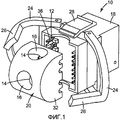
Фиг.1. Аксонометрический вид сзади разъема в соответствии с настоящим изобретением, в частично разобранном виде.Figure 1. Axonometric rear view of the connector in accordance with the present invention, in a partially disassembled form.
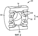
Фиг.2. Аксонометрический вид направляющего элемента разъема, изображенного на фиг.1.Figure 2. Axonometric view of the guide element of the connector shown in figure 1.
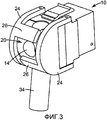
Фиг.3. Вид разъема, изображенного на фиг.1, с присоединенным к нему кабелем.Figure 3. View of the connector shown in figure 1, with a cable attached to it.
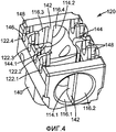
Фиг.4. Еще одно воплощение направляющего элемента.Figure 4. Another embodiment of the guide element.
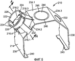
Фиг.5. Аксонометрический вид экрана в соответствии с настоящим изобретением.Figure 5. Axonometric view of the screen in accordance with the present invention.
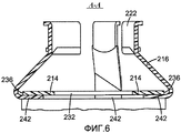
Фиг.6. Поперечное сечение по плоскости А-А фиг.5.6. The cross section along the plane aa of Fig.5.
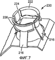
Фиг.7. Фрагмент экрана, изображенного на фиг.5.7. A fragment of the screen shown in Fig.5.
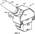
Фиг.8. Экран, установленный на разъем.Fig. 8. Screen mounted on the connector.
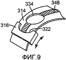
Фиг.9. Схематическое изображение еще одного воплощения экрана в соответствии с настоящим изобретением.Fig.9. Schematic illustration of another embodiment of the screen in accordance with the present invention.
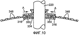
Фиг.10. Поперечное сечение воплощения экрана, изображенного на фиг.9.Figure 10. Cross section of an embodiment of the screen depicted in Fig.9.
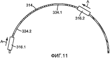
Фиг.11. Вид сбоку воплощения, изображенного на фиг.9 и 10.11. A side view of the embodiment depicted in figures 9 and 10.
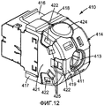
Фиг.12. Аксонометрический вид еще одного воплощения разъема в соответствии с настоящим изобретением.Fig. 12. Axonometric view of another embodiment of a connector in accordance with the present invention.
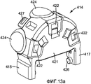
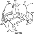
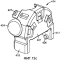
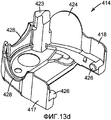
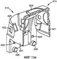
Фиг.13а-13е. Аксонометрический вид экранирующих дуг разъема, изображенного на фиг.12.Figa-13e. Axonometric view of the shielding arcs of the connector shown in Fig.12.
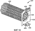
Фиг.14. Аксонометрический вид удлинителя разъема, изображенного на фиг.12.Fig.14. Axonometric view of the extension cord of the connector shown in Fig.12.
Фиг.15. Аксонометрический вид разъема, изображенного на фиг.12, с удлинителем, изображенным на фиг.14.Fig.15. Axonometric view of the connector shown in Fig.12, with the extension cord shown in Fig.14.
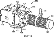
Фиг.16. Аксонометрический вид разъема, изображенного на фиг.12, с удлинителем, изображенным на фиг.14, и хомутом для кабеля.Fig.16. Axonometric view of the connector shown in Fig. 12, with the extension cord shown in Fig. 14, and a cable tie.
Подробное описание изобретенияDETAILED DESCRIPTION OF THE INVENTION
Описываемые ниже экраны прикрепляются к задней стороне разъема. В данном случае термин «передняя сторона» означает ту сторону разъема, с которой прикрепляется, например вставляется, ответный разъем. Противоположная ей сторона определяется соответственно как «задняя сторона». Описываемые в настоящем изобретении экраны прикрепляются с задней стороны. Однако они могут быть протяженными к одной или более верхним поверхностям, одной или более нижним поверхностям и одной или более боковым поверхностям. Таким образом, описываемые здесь экраны могут обеспечивать экранировку одной или более из упомянутых сторон разъема. Прикрепление экрана к разъему может осуществляться любым из подходящих для этого способов, например, за счет одного или более выступов, входящих в одно или более углублений в разъеме, и/или одного или более углублений или отверстий в экране, входящих в зацепление с одним или более выступом, зацепом или подобным элементом разъема. Подобные элементы могут быть и на экране. Экран может также защелкиваться на разъеме. Более того, любой из вышеприведенных элементов для крепления экрана может быть также обеспечен на направляющем элементе разъема, как будет описано ниже. Экран может быть также частью разъема, предпочтительно выполненного в виде единой структуры с разъемом или в виде встроенной в него части.The screens described below are attached to the back of the connector. In this case, the term "front side" means that side of the connector with which it is attached, for example inserted, a mating connector. The opposite side is defined as the “back side”, respectively. The screens described in the present invention are attached on the rear side. However, they may be extended to one or more upper surfaces, one or more lower surfaces, and one or more side surfaces. Thus, the screens described herein may provide shielding for one or more of the mentioned sides of the connector. The screen can be attached to the connector by any of the methods suitable for this, for example, by means of one or more protrusions included in one or more recesses in the connector, and / or one or more recesses or holes in the screen engaged with one or more protrusion, hook or similar element of the connector. Similar items can be on the screen. The screen may also snap into place on the connector. Moreover, any of the above screen mount elements may also be provided on the guide element of the connector, as will be described below. The screen may also be part of the connector, preferably made in the form of a single structure with the connector or in the form of a built-in part.
Кабель, имеющий экранирующую оболочку, может подсоединяться к разъему с задней стороны. В этом смысле не имеется в виду, что подсоединение должно быть сделано точно с задней стороны. Скорее, имеется в виду, что кабель входит в соединитель в целом с задней стороны, однако в то же время в какой-то степени с верхней, нижней или одной из боковых сторон. То есть подсоединение кабеля к разъему может производиться с любой стороны, кроме стороны, с которой производится подключение ответного разъема.A cable having a shielding can be connected to the connector on the rear side. In this sense, it does not mean that the connection must be made exactly from the back. Rather, it is understood that the cable enters the connector as a whole from the rear, but at the same time to some extent from the top, bottom, or one of the sides. That is, the cable to the connector can be connected from any side, except for the side from which the mating connector is connected.
Описываемые здесь экраны являются экранами для разъемов, имеющими основную часть корпуса экрана и предназначенные для экранировки одной или более задних, верхней, нижней и одной или более боковых сторон. Таким образом может осуществляться экранировка разъема. Чтобы продолжить данную экранировку к кабелю и связать ее с экранировкой прочих устройств и одним общим заземлением, экран имеет один или более выступающих элементов, которые можно соединить с экранирующей оболочкой кабеля. Экранирующая оболочка кабеля может быть, например, выполнена в виде оплетки. Выступающий элемент для соединения с экранирующей оболочкой кабеля может быть сформирован любым подходящим для этого образом, как будет подробно описано ниже. В первом воплощении имеется по меньшей мере один выступающий участок, который может быть прикреплен по меньшей мере к двум различным входным участкам экранировки разъема. Иными словами, экранировка разъема имеет два или более входных участков для прокладки через них кабеля. Таким образом универсальность разъема с экранировкой увеличивается за счет наличия по меньшей мере одного выступающего участка, который может быть прикреплен по меньшей мере к двум входным участкам. Таким образом, при необходимости пропустить кабель через экран в разъем выступающий элемент для обеспечения контакта экранирующей оболочки кабеля с экраном разъема может быть установлен в подходящем месте. Таким образом достигается непрерывность заземления между кабелем и разъемом. Установка выступающих элементов может осуществляться за счет зацепления одного или более выступов или зацепов с соответствующими ответными элементами экрана. Более того, выступающий элемент может иметь гнущиеся участки, которые могут быть согнуты по краю экрана разъема. Во втором воплощении удлинитель может быть установлен или наживлен на экран разъема с возможностью его последующего смещения вдоль экрана разъема по меньшей мере к двум различным входным участкам. Таким образом удлинитель может быть смещен вдоль экрана в нужное положение, на входе кабеля в разъем. Такая конструкция позволяет легко и достаточно универсально обеспечить экранировку соединения и приспособиться под нужды конкретной ситуации. В данном случае по меньшей мере один удлинитель может быть сдвигаемым вдоль экрана разъема. Более того, по меньшей мере один удлинитель может иметь один или более гибких, сгибаемых или подобным им участков таким образом, что по меньшей мере данные участки удлинителя, а может быть и сам удлинитель целиком, могут быть смещены к двум различным входным участкам за счет сгибания или деформации упомянутых гибких участков. В данном случае удлинитель может быть установлен в фиксированном месте экрана разъема и за счет деформации может настраиваться по меньшей мере под два различных входных участка.The screens described here are connector screens having a main body of the screen and designed to shield one or more rear, upper, lower, and one or more side sides. In this way, the connector can be shielded. To continue this shielding to the cable and associate it with the shielding of other devices and one common ground, the screen has one or more protruding elements that can be connected to the cable shielding. The cable shielding may, for example, be in the form of a braid. The protruding element for connection to the cable shielding can be formed in any suitable way for this, as will be described in detail below. In the first embodiment, there is at least one protruding portion that can be attached to at least two different input portions of the connector shielding. In other words, the shield of the connector has two or more input sections for laying a cable through them. In this way, the versatility of the shielded connector is enhanced by the presence of at least one protruding portion that can be attached to at least two inlet portions. Thus, if necessary, pass the cable through the screen into the connector protruding element to ensure contact of the cable shielding cable with the shield of the connector can be installed in a suitable place. In this way, ground continuity between the cable and the connector is achieved. The installation of the protruding elements can be carried out by engaging one or more protrusions or hooks with the corresponding response elements of the screen. Moreover, the protruding element may have bendable portions that can be bent along the edge of the connector screen. In a second embodiment, the extension cord may be mounted or bent on the connector screen with the possibility of its subsequent displacement along the connector screen to at least two different input sections. Thus, the extension cord can be shifted along the screen to the desired position, at the input of the cable into the connector. This design makes it possible to easily and universally provide shielding of the connection and adapt to the needs of a particular situation. In this case, at least one extension may be movable along the connector screen. Moreover, at least one extension cord may have one or more flexible, bendable or similar portions in such a way that at least these extension portions, and possibly the entire extension cord itself, can be shifted to two different input sections due to bending or deformation of said flexible sections. In this case, the extension cord can be installed in a fixed place on the connector screen and, due to deformation, can be adjusted to at least two different input sections.
Еще в одном воплощении экран может изначально иметь большее количество удлинителей, чем необходимо, таким образом, что экран может настраиваться под нужды конкретной ситуации за счет удаления ненужных удлинителей. Если возле каждого удлинителя имеются дополнительные проемы для кабеля, ненужные удлинители могут быть использованы для закрытия неиспользуемых проемов, тем самым позволяя обеспечить практически полную экранировку кабеля.In yet another embodiment, the screen may initially have more extension cords than necessary, so that the screen can be customized to fit a particular situation by removing unnecessary extension cords. If there are additional cable openings near each extension cord, unnecessary extension cords can be used to close unused openings, thereby allowing for almost complete cable screening.
По меньшей мере один такой входной участок может иметь по меньшей мере один удаляемый участок, то есть часть экрана, которую можно удалить, чтобы продеть через образовавшийся проем кабель. Удаляемый участок может быть определен намеченными точками слома и/или может быть элементом, частично отделенным от экрана разъема и скрепленным с ним маленькими стенками или перешейками, которые легко ломаются. В данном контексте один или более удаляемых участков могут быть приспособлены под трансформацию в один или более удлинителей, соединяемых с экранирующей оболочкой кабеля. Иными словами, в одном состоянии удлинители могут представлять собой часть корпуса экрана разъема, а во втором состоянии могут быть отогнуты и использоваться собственно как удлинители, контактирующие с экранирующей оболочкой кабеля. В данном случае весь экран может быть выполнен в виде одного структурно целого компонента, включающего основную часть экрана разъема и один или более удлинителей. Более того, выступы, зажимы или подобные им элементы, с помощью которых производится крепление экрана к разъему, могут быть выполнены структурно целыми с экраном.At least one such inlet portion may have at least one removable portion, that is, a portion of the screen that can be removed to pass through the cable opening. The area to be removed may be determined by the designated break points and / or may be an element partially separated from the connector screen and fastened with small walls or isthmuses that break easily. In this context, one or more removable sections can be adapted for transformation into one or more extension cords connected to the cable shielding. In other words, in one state, the extension cords can be part of the connector shield housing, and in the second state, they can be bent and used as extension cords in contact with the cable shielding. In this case, the entire screen can be made in the form of one structurally integral component, including the main part of the connector screen and one or more extension cords. Moreover, protrusions, clamps or similar elements with which the screen is attached to the connector can be structurally integral with the screen.
В обоих воплощениях, то есть в воплощении, в котором удлинитель крепится к экрану разъема, и в воплощении, в котором удлинитель смещается вдоль экрана разъема, по меньшей мере один удлинитель может быть загнут вокруг по меньшей мере одного края экрана разъема. Загнутый участок может служить чем-то вроде направляющей для движения удлинителя вдоль экрана разъема, так как он фактически держится изнутри за край разъема. Те проемы, к которым может быть придвинут по меньшей мере один удлинитель или возле которых он может быть закреплен для соединения с экранирующей оболочкой кабеля, входящего в проем, могут быть сформированы в виде входных участков. Экран может иметь два асимметрично расположенных входных участка. В данном случае один входной участок может быть расположен практически по центру экрана и соответствовать центрально расположенному проему разъема для приема кабеля, как будет подробно описано ниже. Второй входной участок может быть эксцентричным, и в данном случае разъем может быть описан как асимметричный. Если крепежные элементы, имеющиеся на экране, позволяют проводить его крепление к разъему в любой ориентации, то есть экран является симметричным за исключением положения второго входного участка, экран можно повернуть на 180° вокруг оси проема, расположенного по центру, и при этом эксцентричный проем окажется на противоположной стороне, и таким образом получается, что кабель может входить в экран с трех различных направлений. Экран может также иметь три и более входных участков.In both embodiments, that is, in the embodiment in which the extension cable is attached to the connector screen, and in the embodiment in which the extension cable moves along the connector screen, at least one extension cable can be bent around at least one edge of the connector screen. The bent section can serve as a kind of guide for moving the extension cord along the connector screen, since it actually holds the inside of the edge of the connector. Those openings to which at least one extension cord can be pulled or near which it can be fixed for connection with the cable shielding of the cable entering the opening can be formed in the form of input sections. The screen may have two asymmetrically located input sections. In this case, one input section can be located almost in the center of the screen and correspond to the centrally located opening of the cable receiving connector, as will be described in detail below. The second inlet portion may be eccentric, and in this case, the connector may be described as asymmetrical. If the fasteners on the screen allow it to be mounted to the connector in any orientation, that is, the screen is symmetrical except for the position of the second input section, the screen can be rotated 180 ° around the axis of the opening located in the center, and the eccentric opening will be on the opposite side, and so it turns out that the cable can enter the screen from three different directions. A screen may also have three or more input sections.
В описываемом здесь экране по меньшей мере один удлинитель может включать кольцо или кольцевой сегмент. Кольцо или сегмент кольца могут хорошо подходить для установления электрического контакта экрана с экранирующим слоем кабеля, имеющим, как правило, круглое сечение. Практика показала, что полное кольцо может быть обеспечено по меньшей мере на одном удлинителе. При наличии одного или более удлинителей с кольцами или сегментам колец сегменты могут образовывать кольцо с разрывами. Это позволяет установить контакт экрана с экранирующей оболочкой кабеля практически по всей ее окружности, что обеспечивает особенно хороший контакт. Более того, такое практически полное кольцо может быть сформировано в виде единой структуры с соответствующим удлинителем, и даже со всем экраном. В данном случае контакт между экраном разъема и экранирующей оболочкой кабеля обеспечивается одним элементом, структурно целым с экраном, что дает равномерный импеданс соединения, что особенно важно для эффективного направления индуцируемых в экране токов на землю. В частности, если имеется более одного удлинителя, наличие таких кольцевых элементов на всех из них обеспечивает одинаковый импеданс всех удлинителей.In the screen described herein, at least one extension may include a ring or an annular segment. The ring or segment of the ring may be well suited to establish electrical contact between the screen and the shielding layer of the cable, typically having a circular cross section. Practice has shown that a complete ring can be provided on at least one extension cord. If one or more extenders with rings or ring segments are present, the segments may form a ring with gaps. This makes it possible to establish contact between the screen and the cable shielding practically over its entire circumference, which ensures especially good contact. Moreover, such an almost complete ring can be formed as a single structure with an appropriate extension cord, and even with the entire screen. In this case, the contact between the shield of the connector and the shield of the cable is provided by one element, structurally integral with the shield, which gives a uniform impedance of the connection, which is especially important for the effective direction of the currents induced in the shield to the ground. In particular, if there is more than one extension cord, the presence of such ring elements on all of them provides the same impedance of all extension cords.
Может иметь смысл, чтобы по меньшей мере в одном удлинителе или одном кольце (или кольцевом сегменте) имелось по меньшей мере одно ребро поперек удлинителя или вдоль кольца (или кольцевого сегмента) соответственно. Ребро, которое можно также назвать гребнем или кольцеобразным выступом, можно использовать для расположения или направления хомута, в частности хомута кабеля, ленты, проволочной скрутки или другого элемента, который может быть использован для стяжки одного или более удлинителей, кольцевых сегментов или колец вокруг экранирующей оболочки кабеля.It may make sense that at least one extension cord or one ring (or ring segment) has at least one rib across the extension cord or along the ring (or ring segment), respectively. An edge, which can also be called a ridge or ring-shaped protrusion, can be used to position or guide a cable tie, in particular a cable tie, tape, wire twist or other element that can be used to tie one or more extensions, ring segments or rings around the shielding cable.
Имеет также смысл, чтобы по меньшей мере один удлинитель был упругим по отношению к экрану разъема. В таком случае один или более удлинителей, находясь в первом состоянии, были разделены друг от друга на расстояние, достаточное для того, чтобы между данными удлинителями мог быть вставлен кабель. Когда кабель вставлен, и необходимо обжать удлинители вокруг экранирующей оболочки кабеля, их упругость поможет обеспечить их лучшее прижатие к экранирующей оболочке кабеля.It also makes sense that at least one extension is resilient with respect to the connector shield. In this case, one or more extension cords, being in the first state, were separated from each other by a distance sufficient so that a cable could be inserted between these extension cords. When the cable is inserted and extension cords need to be squeezed around the cable shielding, their resilience will help ensure that they are better pressed against the cable shielding.
Может также иметь смысл, если экран разъема имеет по меньшей мере один, а лучше много элементов зацепления, и по меньшей мере один удлинитель имеет по меньшей мере один участок зацепления, и при этом указанные элементы и участки зацепления были взаимно приспособлены для того, чтобы блокировать смещение удлинителя по меньшей мере в одном направлении. В этом случае указанные участок зацепления и элемент зацепления могут позволять смещать по меньшей мере один удлинитель к входному участку экрана разъема, и блокировать последующее его смещение с данного положения, то есть от входного участка. Таким образом может обеспечиваться правильное положение одного или более удлинителей. Участки зацепления могут быть сформированы в виде рельсов, имеющих одно или более углублений и/или выступов. По меньшей мере один элемент зацепления удлинителя может быть адаптирован для взаимодействия с указанными участками зацепления указанным выше образом. В данном контексте элементы зацепления могут быть выполнены с возможностью их разъединения, так, что, например, приподняв его пальцем из участка зацепления экрана разъема, удлинитель можно сдвинуть в направлении, которое было заблокировано элементом зацепления. Описанные здесь экраны могут, в частности, иметь два смещаемых удлинителя, каждый из который имеет практически полукольцевой сегмент, и при этом указанные два удлинителя могут быть смещены друг к другу, окружая входной участок. Когда в указанный вход вставлен кабель, экранировка окружает его практически на 360° за счет замыкания описанных выше полукольцевых сегментов.It may also make sense if the connector screen has at least one, and preferably a lot of engagement elements, and at least one extension cord has at least one engagement portion, wherein said engagement elements and portions are mutually adapted to block extension of the extension cord in at least one direction. In this case, the indicated engagement section and the engagement element can allow at least one extension to be displaced to the input section of the connector screen and block its subsequent displacement from this position, that is, from the input section. In this way, one or more extension cords can be correctly positioned. The engagement portions may be formed in the form of rails having one or more recesses and / or protrusions. At least one engagement member of the extension cord may be adapted to interact with said engagement portions in the manner described above. In this context, the engagement elements can be made so that they can be disconnected, such that, for example, by lifting it with a finger from the engagement portion of the connector screen, the extension cord can be shifted in a direction that was blocked by the engagement element. The screens described here may, in particular, have two movable extension cords, each of which has a substantially semi-annular segment, and these two extension cords may be offset to each other, surrounding the input section. When a cable is inserted into the specified input, shielding surrounds it almost 360 ° due to the closure of the above-described half-ring segments.
Следует отметить, что в настоящем описании представлен однокомпонентный экран, имеющий кольцо, образующее с ним единую структуру, или множество кольцевых сегментов, образующих с ним единую структуру и которые могут быть использованы как для установления электрического контакта с экранирующей оболочкой кабеля, так и в качестве зажима для снятия механического напряжения кабеля. Такой экран, имеющий одну или более черт, описанных выше и ниже, но не обязательно имеющий такую черту, как по меньшей мере один удлинитель, выполненный с возможностью установки по меньшей мере на двух различных входных участках, или с возможностью смещения по меньшей мере к двум различным входным участкам, следует рассматривать как предмет данного изобретения.It should be noted that in the present description a one-component screen is presented having a ring forming a single structure with it, or a plurality of ring segments forming a single structure with it and which can be used both to establish electrical contact with the cable shielding and as a clamp to relieve mechanical stress on the cable. Such a screen having one or more features described above and below, but not necessarily having such a feature as at least one extension cord, configured to be installed in at least two different input portions, or with the possibility of displacement to at least two different inlet areas should be considered as the subject of this invention.
Как было указано выше, описанные выше экраны придают дополнительную универсальность разъему, применяемому в области телекоммуникаций и к которому может прикрепляться экран. Более того, изобретение обеспечивает также комбинацию разъема и по меньшей мере одного экрана, имеющего одну или более черт, описанных выше и ниже. В данном контексте может иметь смысл дополнительное обеспечение по меньшей мере одного хомута для кабеля для обжима одного или более удлинителей, кольцевых сегментов или практически целого кольца вокруг экранирующей оболочки кабеля, заведенного в разъем.As mentioned above, the screens described above give additional versatility to the connector used in the field of telecommunications and to which the screen can be attached. Moreover, the invention also provides a combination of a connector and at least one screen having one or more features described above and below. In this context, it may make sense to additionally provide at least one cable tie for crimping one or more extension cords, ring segments, or virtually an entire ring around the cable shielding of the cable wound into the connector.
Настоящее изобретение относится к разъемам, имеющим контакты, к которым присоединяются провода.The present invention relates to connectors having contacts to which wires are connected.
Провода могут быть присоединены к контактам внутри разъема, то есть места соединения проводов с контактами могут быть полностью скрыты и/или полностью окружены частями корпуса разъема. Участки контактов, к которым присоединены провода, могут быть сформированы по типу контактов со смещаемой изоляцией или как контакты с лепестками, оборачиваемыми вокруг проводов, или как контакты прочего подходящего типа. Контакты могут иметь открытые участки за пределами разъема для их электрического подключения к контактам ответного разъема. В качестве примеров описываемых здесь разъемов можно привести разъем типа RJ45 или разъем стандарта ICE 60603-7. Провода, присоединяемые к контактам разъема, могут быть собраны в кабель, и описываемый в настоящем изобретении разъем может иметь по меньшей мере три проема, причем в каждый из проемов можно вставить по меньшей мере два провода. Проемы могут быть приспособлены для приема двух проводов (пары проводов, в том числе витой пары), четырех проводов (то есть двух пар) и более проводов. Более того, по меньшей мере один проем может быть рассчитан на прием целого кабеля, в который собраны провода. Кабель может, например, иметь собранные в нем четыре витые пары. Пары проводов могут быть экранированы друг от друга, и вокруг пар может иметься как экранировка, так и электроизолирующий слой. Преимуществом предлагаемого в настоящем изобретении разъема является то, что через проем может быть пропущен целый кабель и уложен в подходящей направляющей для кабеля. Кабель может иметь множество витых пар проводов, например, четыре пары проводов, экранировку каждой пары, и/или общую экранировку вокруг всех пар, заземляющий провод и как самый внешний слой изоляцию.The wires can be connected to the contacts inside the connector, that is, the junction of the wires with the contacts can be completely hidden and / or completely surrounded by parts of the connector housing. The contact areas to which the wires are connected can be formed by the type of contacts with biased insulation or as contacts with petals wrapped around the wires, or as contacts of other suitable type. The contacts may have open areas outside the connector for their electrical connection to the contacts of the mating connector. Examples of the connectors described here are the RJ45 type connector or the ICE 60603-7 standard connector. The wires connected to the connector pins can be assembled into a cable, and the connector described in the present invention can have at least three openings, and at least two wires can be inserted into each of the openings. The openings can be adapted to receive two wires (a pair of wires, including a twisted pair), four wires (that is, two pairs) and more wires. Moreover, at least one opening can be designed to receive a whole cable into which the wires are assembled. A cable may, for example, have four twisted pairs assembled therein. The pairs of wires can be shielded from each other, and around the pairs there can be both shielding and an electrically insulating layer. An advantage of the connector of the present invention is that an entire cable can be passed through the opening and laid in a suitable cable guide. A cable can have many twisted pairs of wires, for example, four pairs of wires, shielding of each pair, and / or common shielding around all pairs, grounding wire and insulation as the outermost layer.
Если проем в разъеме рассчитан на прием целого кабеля, легко понять, что экранировка и электроизоляционный слой кабеля необходимо удалить только до того места кабеля, где провода расходятся между собой для присоединения к контактам. В этой связи следует отметить, что кабель может быть «сбалансирован» за счет того, что в него входят витые пары, которые, кроме того, свиты друг с другом, и имеется соответствующая экранировка. Такое «сбалансированное» состояние кабеля нарушается, когда отдельные пары проводов, или даже отдельные провода, отделяются друг от друга. Другими словами, если проем в разъеме рассчитан на прием целого кабеля, при желании «сбалансированное» состояние кабеля может быть практически сохранено. Данный эффект может быть усилен за счет должного размещения контактов в разъеме, позволяющего проложить провода к контактам с минимальным количеством пересечений витых пар между собой.If the opening in the connector is designed to accept a whole cable, it is easy to understand that the screening and the insulating layer of the cable must be removed only to the point where the wires diverge to connect to the contacts. In this regard, it should be noted that the cable can be "balanced" due to the fact that it includes twisted pairs, which, in addition, are twisted together, and there is a corresponding shielding. This "balanced" state of the cable is broken when individual pairs of wires, or even individual wires, are separated from each other. In other words, if the opening in the connector is designed to receive an entire cable, if desired, the "balanced" state of the cable can be practically saved. This effect can be enhanced by properly placing the contacts in the connector, allowing you to lay the wires to the contacts with a minimum number of intersections of twisted pairs with each other.
Один или более проемов могут быть рассчитаны на прием меньшего количества проводов, чем общее количество проводов в кабеле. Такие проемы могут быть, например, меньшего поперечного сечения, чем сечение кабеля, поэтому, чтобы пропустить в них провода, в определенном месте необходимо снять изоляцию и экранировку с кабеля и разделить провода или пары проводов. Как было определено в некоторых приложениях, если кабель вместе с экранировкой и изоляцией заходит слишком далеко в разъем, это имеет свои недостатки. Например, возникает определенный риск короткого замыкания за счет случайного контакта экранировки с контактами разъема. В таких случаях более целесообразным является удаление изоляции и экранировки на определенном участке конца кабеля, после чего пары проводов могут быть разделены друг от друга и по отдельности заведены в разъем через один или более проемов. При этом пары проводов могут заводиться в разъем (через один или более проемов) с сохранением их индивидуальной экранировки, например, из фольги. Такой способ также имеет преимущества, так как витые пары остаются в витом состоянии и прокладываются в таком состоянии внутри разъема, что обеспечивает их лучшую экранировку.One or more openings can be designed to accept fewer wires than the total number of wires in the cable. Such openings can be, for example, of a smaller cross section than the cable section, therefore, in order to let the wires pass through them, it is necessary to remove the insulation and shielding from the cable at a certain place and separate the wires or pairs of wires. As defined in some applications, if the cable, together with the shielding and insulation, goes too far into the connector, this has its drawbacks. For example, there is a certain risk of a short circuit due to accidental shielding contact with the connector pins. In such cases, it is more advisable to remove insulation and shielding at a certain section of the cable end, after which the pairs of wires can be separated from each other and individually inserted into the connector through one or more openings. In this case, pairs of wires can be inserted into the connector (through one or more openings) while maintaining their individual shielding, for example, from foil. This method also has advantages, since twisted pairs remain in a twisted state and are laid in this state inside the connector, which ensures their better shielding.
Проемы для проводов могут открываться наружу разъема, на сторону, удаленную от контактов. Можно также сказать, что проемы открываются на сторону разъема, с которой к нему подсоединяется кабель. Данная сторона является в целом противоположной стороне подключения ответного разъема. Таким образом, проемы для проводов открываются на сторону разъема, удаленную от контактов. Как было указано выше, все соединения между отдельными проводами и контактами могут быть сформированы внутри разъема.Openings for wires can open outward of the connector, on the side remote from the contacts. You can also say that the openings open on the side of the connector with which the cable is connected to it. This side is generally the opposite side of the mating connector. Thus, the openings for the wires open on the side of the connector, remote from the contacts. As mentioned above, all connections between individual wires and contacts can be formed inside the connector.
Проемы для проводов могут быть относительно простой формы, например, в виде отверстия, предназначенного для пропускания через них проводов или целого кабеля в определенном направлении и в том месте, где сформированы данные проемы или отверстия.The openings for the wires can be of a relatively simple shape, for example, in the form of an opening designed to pass wires or an entire cable through them in a certain direction and at the place where these openings or holes are formed.
Универсальность разъема увеличивается за счет того, что проемы для проводов ориентированы по меньшей мере в трех различных направлениях. Во-первых, проемы для проводов открываются наружу разъема. Поэтому кабель или провод можно вставить в подходящий проем снаружи разъема. С этой точки зрения наличие проемов, ориентированных по меньшей мере в трех направлениях, может дать дополнительные преимущества, например, чтобы в разъем можно было завести кабели, приходящие из трех различных направлений, и там безопасно и надежно соединить с контактами. Благодаря наличию по меньшей мере трех направлений ориентации проемов для запуска в разъем того или иного кабеля можно выбрать проем, наиболее подходящий по ориентации с направлением подхода к разъему провода или кабеля. В частности, кабели, приходящие из-под пола, из потолка, проложенные в каналах или за панелями обшивки, можно завести в такой разъем, практически сохраняя их направление вплоть до определенного места внутри разъема. Это позволяет свести к минимуму число нежелательных изгибов кабеля, что особенно важно, если с кабеля удалена изоляция или экранировка, потому что именно в таком состоянии, то есть с удаленной изоляцией и/или экранировкой, особенно трудно сохранить требуемое направление хода проводов.The versatility of the connector is enhanced by the fact that the openings for the wires are oriented in at least three different directions. Firstly, the openings for the wires open outward of the connector. Therefore, a cable or wire can be inserted into a suitable opening outside the connector. From this point of view, the presence of openings oriented in at least three directions can provide additional advantages, for example, so that cables coming from three different directions can be inserted into the connector, and there it can be safely and reliably connected to the contacts. Due to the presence of at least three directions of orientation of the openings for launching one or another cable into the connector, it is possible to choose the opening most suitable for orientation with the direction of approach to the wire or cable connector. In particular, cables coming from under the floor, from the ceiling, laid in channels or behind cladding panels, can be routed into such a connector, practically preserving their direction up to a certain place inside the connector. This helps to minimize the number of undesirable cable bends, which is especially important if the insulation or shielding is removed from the cable, because it is in this state, that is, with the insulation and / or shielding removed, that it is especially difficult to maintain the required direction of travel of the wires.
По меньшей мере три проема могут, например, быть открытыми в трех направлениях радиально от центральной области разъема или места предполагаемой разделки кабеля и разведения отдельных проводов друг от друга.At least three openings can, for example, be open in three directions radially from the central region of the connector or the location of the intended cable cut and separate wires from each other.
Таким образом можно значительно избежать нежелательной кривизны кабеля на входе в разъем. Более того, провода или кабель целиком могут быть проложены достаточно близко к контактам, где провода могут быть отделены друг от друга, и достаточно близко от данного места подсоединены к контактам. Таким образом, все нежелательные изгибы проводов для придания им нужной ориентации относительно контактов могут быть контролируемыми за счет наличия в разъеме направляющих углублений соответствующей ориентации и прокладки проводов в данных углублениях (что будет подробно описано ниже). В частности, может и вовсе не требоваться сгибать целый кабель. Вместо этого в определенном месте можно разделить провода и согнуть их нужным образом. При этом неизбежные места сгиба проводов могут находиться на минимальном расстоянии от контактов разъема.In this way, unwanted cable curvature at the input to the connector can be significantly avoided. Moreover, the wires or the cable as a whole can be laid close enough to the contacts, where the wires can be separated from each other, and close enough to this place are connected to the contacts. Thus, all undesirable bends of the wires to give them the desired orientation with respect to the contacts can be controlled by the presence of the corresponding orientation in the connector of the guide recesses and the laying of wires in these recesses (which will be described in detail below). In particular, it may not be necessary to bend the whole cable at all. Instead, you can separate the wires in a specific place and bend them in the right way. In this case, the inevitable places of bending the wires can be at a minimum distance from the contacts of the connector.
Таким образом могут быть сделаны надежные соединения между контактами и проводами, и при этом вплоть до места, очень близкого к контактам, может сохраняться витое состояние пар проводов, а разделение между парами проводов и экранировка кабеля тоже могут быть сохранены до этого места. За счет этого эффект «перекрестных разговоров» может быть сведен к минимуму. Более того, четко определенное расположение отдельных проводов и сведение к минимуму их смещения от правильного положения или ориентации обеспечивают высокие характеристики передачи сигнала кабелем.In this way, reliable connections between the contacts and wires can be made, and up to a point very close to the contacts, the twisted state of the pairs of wires can be preserved, and the separation between the pairs of wires and cable shielding can also be saved to this place. Due to this, the effect of "cross talk" can be minimized. Moreover, a clearly defined arrangement of individual wires and minimizing their displacement from the correct position or orientation provide high cable signal transmission characteristics.
Описанный здесь разъем может устанавливаться на печатные платы. В таком случае кабель также может присоединяться к разъему способом, описанным выше. В качестве альтернативы, или в дополнение к таким кабелям, кабель может быть соединен с проводящими дорожками печатной платы, соединенными в свою очередь с контактами разъема. Печатные платы часто используются в активном сетевом оборудовании, например, в серверах. Более того, разъемы могут быть установлены на панелях или розетках подключения оборудования, расположенных на стенах или в кабельных каналах.The connector described here can be mounted on circuit boards. In this case, the cable can also be connected to the connector in the manner described above. Alternatively, or in addition to such cables, the cable may be connected to the conductive paths of the printed circuit board, connected in turn to the contacts of the connector. Printed circuit boards are often used in active network equipment, such as servers. Moreover, the connectors can be installed on panels or sockets for connecting equipment located on walls or in cable channels.
Проемы для проводов могут быть собраны в пары или в группы по четыре, при этом проемы одной пары или одной группы будут открываться в одном направлении. Одна группа проемов может быть рассчитана на проход через нее всех проводов одного кабеля. За счет этого все провода кабеля, приходящего к разъему в определенном направлении, сохраняют это направление, проходя через проемы, вплоть до определенного места внутри разъема. То же самое справедливо, если один или более проемов рассчитаны на прохождение через них целого кабеля. В данном случае кабель может кабель может приходить в разъем по меньшей мере с трех различных направлений, и нет необходимости его сгибать перед входом в разъем. Более того, если проемы собраны в пары или в группы по четыре, каждый из проемов может быть рассчитан на прием половины или четверти проводов в кабеле. Так, например, если в кабеле восемь проводов, то есть четыре пары, то каждый из пары проемов рассчитан на прохождение четырех проводов, то есть двух пар. Если в разъеме имеется группа из четырех проемов, то в каждый из проемов данной группы можно пропустить два провода, то есть одну пару. При такой конструкции разъема провода могут быть достаточно разделены друг от друга уже на входе в разъем, что дает дополнительные преимущества с точки зрения минимизации эффекта перекрестных разговоров.The openings for wires can be assembled in pairs or in groups of four, while the openings of one pair or one group will open in one direction. One group of openings can be designed to pass through it all the wires of one cable. Due to this, all the wires of the cable coming to the connector in a certain direction preserve this direction, passing through the openings, up to a certain place inside the connector. The same is true if one or more openings are designed to allow a cable to pass through them. In this case, the cable may come into the connector from at least three different directions, and there is no need to bend it before entering the connector. Moreover, if the openings are assembled in pairs or in groups of four, each of the openings can be designed to receive half or a quarter of the wires in the cable. So, for example, if there are eight wires in the cable, that is, four pairs, then each of the pair of openings is designed to pass four wires, that is, two pairs. If the connector has a group of four openings, then in each of the openings of this group you can skip two wires, that is, one pair. With this design of the connector, the wires can be quite separated from each other at the entrance to the connector, which gives additional advantages in terms of minimizing the effect of cross talk.
По меньшей мере рядом с одним из проемов для проводов может быть сформирована направляющая, и она может иметь некоторую протяженность в направлении прокладки провода или кабеля, определяя таким образом направление и форму провода или кабеля, прокладываемых по данной направляющей. Направляющая может быть практически прямой, кривой или угловой. При наличии криволинейных участков и/или углов, и если направляющая рассчитана на прокладку целого кабеля, это позволяет сгибать кабель целиком, так что при этом не возникает нарушений ориентации отдельных проводов и ухудшение приемопередаточных свойств кабеля за счет эффекта «перекрестных разговоров» сводится к минимуму. Направляющие для проводов и кабелей могут быть сформированы в виде различных структур, например, перегородок и/или простенков, рассчитанных на удержание отдельных проводов или групп проводов отдельно друг от друга. Более того, в разъеме могут быть выполнены каналы, имеющие закрытое поперечное сечения, для направления отдельных проводов или групп проводов к тем контактам, к которым они должны присоединяться. В дополнение к направляющим для проводов или кабелей или в качестве альтернативы в разъеме может иметься цветовая маркировка для облегчения правильного подключения проводов к контактам разъема. По меньшей мере одна направляющая может быть рассчитана на прием целого кабеля, содержащего провода, которые должны быть подключены к контактам разъема. Прокладка в направляющей целого кабеля позволяет свести шанс неправильной прокладки отдельных проводов к минимуму. Однако, как было сказано выше, может иметь смысл, если по меньшей мере одна направляющая рассчитана на прием меньшего количества проводов, например, только одной пары проводов. Может также иметь смысл наличие у разъема корпуса и по меньшей мере одного направляющего элемента. В направляющем элементе может быть сформирован по меньшей мере один проем для проводов. И корпус, и направляющая могут быть сконструированы так, чтобы обеспечивать максимальную функциональность разъема. Так, например, в конструкцию корпуса могут входить зацепы, отверстия для винтов и прочие структуры, позволяющие устанавливать разъем на панель, в розетку или иные места, как было описано выше. В дополнение к этому направляющий элемент может включать отдельные направляющие для проводов и кабелей, как было писано выше, любой подходящей для этого структуры, включая те структурные конфигурации, что были описаны выше.A guide may be formed at least near one of the openings for the wires, and it may have a certain length in the direction of laying the wire or cable, thereby determining the direction and shape of the wire or cable laid along this guide. The guide can be almost straight, curved or angular. In the presence of curved sections and / or corners, and if the guide is designed for laying a whole cable, this allows the cable to be bent as a whole, so that there is no misalignment of individual wires and the deterioration of the transmission and transmission properties of the cable due to the effect of “cross talk” is minimized. Guides for wires and cables can be formed in the form of various structures, for example, partitions and / or piers, designed to hold individual wires or groups of wires separately from each other. Moreover, channels having a closed cross-section can be made in the connector to direct individual wires or groups of wires to the contacts to which they must be connected. In addition to guides for wires or cables, or alternatively, the connector may be color coded to facilitate proper wiring to the connector pins. At least one guide can be designed to receive a whole cable containing wires that must be connected to the connector pins. Laying the entire cable in the guide allows you to minimize the chance of incorrect wiring of individual wires. However, as mentioned above, it may make sense if at least one rail is designed to receive fewer wires, for example, only one pair of wires. It may also make sense for the housing connector and at least one guide element. At least one wire opening may be formed in the guide member. Both the housing and the rail can be designed to provide maximum connector functionality. So, for example, hooks, screw holes, and other structures that allow you to install the connector on a panel, in an outlet, or other places, as described above, can be included in the body structure. In addition, the guide element may include separate guides for wires and cables, as described above, of any suitable structure for this, including those structural configurations that have been described above.
Направляющий элемент может быть адаптирован для движения вперед к контактам и присоединения проводов к контактам. Данное движение и возникающее в результате его соединение проводов с контактами может быть произведено вручную без необходимости использования какого-либо инструмента.The guide element can be adapted to move forward to the contacts and connect the wires to the contacts. This movement and the resulting connection of wires with contacts can be done manually without the need for any tool.
Направляющий элемент может иметь не только проемы и находящиеся рядом с ними направляющие, но также по меньшей мере одно углубление для приема по меньшей мере одного единичного провода. Углубление может быть обращено к контактам таким образом, что на него можно уложить отдельный провод, и оно будет поддерживать его соединение с контактом. Углубления для укладки отдельных проводов могут быть сформированы в виде любых подходящих для этого структур, например, в виде ребер или каналов.The guide element may have not only openings and guides adjacent to them, but also at least one recess for receiving at least one single wire. The recess can be turned to the contacts in such a way that a separate wire can be laid on it, and it will support its connection with the contact. The recesses for laying individual wires can be formed in the form of any suitable structures for this, for example, in the form of ribs or channels.
Контакты могут быть сформированы в виде контактов, смещающих изоляцию, то есть имеющих контактную щель, в которую проталкивается провод, и при этом с него срезается изоляция и устанавливается контакт между лапками, образующими щель, и металлической жилой провода. Было определено, что когда провода уложены в углубления, такая их прокладка позволяет лучше протолкнуть их в щели. С этой точки зрения может иметь смысл наличие по меньшей мере одной прорези для расположения по меньшей мере одного контакта в направляющем элементе. Более того, указанная прорезь, или несколько прорезей, могут использоваться совместно с контактами, расположенными в них, для направления направляющего элемента при его движении к контактам. В качестве альтернативы, или в дополнение к данному решению, в разъеме могут использоваться дополнительные направляющие элементы для обеспечения правильного движения направляющего элемента.The contacts can be formed in the form of contacts shifting the insulation, that is, having a contact slot into which the wire is pushed, and the insulation is cut off from it and contact is established between the tabs forming the gap and the metal core wire. It was determined that when the wires are laid in the recesses, such laying them allows you to better push them into the cracks. From this point of view, it may make sense to have at least one slot for positioning at least one contact in the guide element. Moreover, the specified slot, or several slots, can be used in conjunction with the contacts located in them, to guide the guide element when it moves to the contacts. Alternatively, or in addition to this solution, additional guide elements may be used in the connector to ensure proper movement of the guide element.
Более того, описанный выше этап проталкивания уложенного в углублении провода в контактную щель может проходить легче, если по меньшей мере одно углубление и по меньшей мере одна прорезь пересекаются между собой. Как было указано выше, для приведения проводов в соединение с контактами может быть предусмотрено сдвижение направляющего элемента к контактам. Может иметь смысл наличие в корпусе по меньшей мере одного ведущего элемента для ведения направляющего элемента к контактам. Такой ведущий элемент поможет оператору, выполняющему монтаж проводов, установить требуемые соединения. Может быть особенно полезным выполнение по меньшей мере одного ведущего элемента в виде вращающейся дуги, имеющей по меньшей мере один выступ, двигающий направляющий элемент при вращении дуги вокруг оси. Это обеспечивает наиболее легкое приведение в действие направляющего элемента со стороны ведущего элемента. Более того, за счет наличия выступа может быть использован эффект рычага. Испытания описанного в настоящем документе разъема показали, что направляющая достаточно легко придвигается к контактам при наличии двух выступов. Два выступа могут быть расположены таким образом, что между ними будет находиться по меньшей мере один проем для проводов. При такой конфигурации легкое приведение направляющего элемента в действие может сочетаться с легким доступом к разъемам для проводов.Moreover, the above-described step of pushing the wires laid in the recess into the contact slot can be easier if at least one recess and at least one slot intersect each other. As mentioned above, to bring the wires into contact with the contacts, a movement of the guide element to the contacts may be provided. It may make sense to have at least one drive element in the housing to guide the guide element to the contacts. Such a lead will help the operator installing the wires to establish the required connections. It may be especially useful to provide at least one leading element in the form of a rotating arc having at least one protrusion moving the guiding element when the arc rotates about an axis. This provides the easiest actuation of the guide element from the leading element. Moreover, due to the presence of the protrusion, the lever effect can be used. Tests of the connector described herein have shown that the guide moves easily enough to the contacts with two protrusions. Two protrusions can be arranged so that between them there will be at least one opening for the wires. With this configuration, the easy actuation of the guide element can be combined with easy access to the wire connectors.
Возможно также функционирование ведущего элемента как экрана. Чтобы он мог работать как экран, ведущий элемент может содержать электропроводящий материал, например, материал на основе алюминия или другой подходящий электропроводящий материал. Кроме того, ведущий элемент, функционирующий как экран, может покрывать почти всю заднюю сторону разъема. Такое воплощение, в котором ведущий элемент имеет две функции - собственно ведущего элемента и экранировки разъема, дает дополнительное преимущество, состоящее в том, что для сборки разъема требуется меньшее количество частей.It is also possible the functioning of the host element as a screen. In order for it to function as a screen, the driving element may comprise an electrically conductive material, for example, an aluminum-based material or other suitable electrically conductive material. In addition, a drive element that functions as a screen can cover almost the entire rear side of the connector. Such an embodiment, in which the drive element has two functions — the drive element itself and the shield of the connector, provides the additional advantage that fewer parts are required to assemble the connector.
В то время как описанные здесь разъемы могут быть выполнены в виде вилок, наиболее предпочтительными воплощениями изобретения представляются разъемы в виде розеток.While the connectors described herein can be made in the form of plugs, the most preferred embodiments of the invention are connectors in the form of sockets.
В соответствии со способом экранировки разъема, предлагаемым в рамках настоящего изобретения, готовится экран, имеющий одну или более черт, описанных выше. В данном контексте по меньшей мере один удлинитель может быть установлен на экран разъема или смещен вдоль экрана разъема в требуемое положение. Дополнительно может быть выполнен любой из указанных выше этапов способа экранировки, например, загиб части удлинителя по краю экрана разъема, и/или удаление отламываемой части и/или отгиб по меньшей мере одного удлинителя от экрана, а также любые другие этапы, описанные выше. На последующем этапе кабель продевается через экран вблизи по меньшей мере одного удлинителя. Затем провода кабеля могут быть подсоединены к контактам разъема. После этого к разъему может быть прикреплен экран, и к экранировке кабеля может быть присоединен по меньшей мере один удлинитель.According to a connector shielding method of the present invention, a screen having one or more of the features described above is prepared. In this context, at least one extension may be mounted on the connector screen or offset along the connector screen to the desired position. Additionally, any of the above steps of the shielding method can be performed, for example, bending part of the extension cord along the edge of the connector screen, and / or removing the part to be broken off and / or bending at least one extension cord from the screen, as well as any other steps described above. In a subsequent step, the cable is passed through the screen in the vicinity of at least one extension cord. Then the cable wires can be connected to the connector pins. After that, a shield can be attached to the connector, and at least one extension cable can be attached to the cable shielding.
В данном контексте этап присоединения по меньшей мере одного удлинителя к экранировке кабеля может включать придвижение удлинителя к экранирующей оболочке кабеля. Это может делаться, например, для приведения одного или более кольцевых сегментов в тесный контакт с экранирующей оболочкой кабеля. Для обеспечения такого контакта и/или зажатия кабеля вокруг одного или более удлинителей, одного или более кольцевых сегментов или целого кольца может быть зажат хомут, например кабельный хомут, лента, проволочная скрутка или аналогичный крепежный элемент. Более того, один или более удлинителей могут иметь структурные элементы, позволяющие им сцепляться друг с другом. Так, например, могут иметься один или более выступов.In this context, the step of attaching at least one extension cord to the cable shielding may include moving the extension cord to the cable shielding. This can be done, for example, to bring one or more ring segments into close contact with the cable shielding. To ensure such contact and / or cable clamping around one or more extension cords, one or more ring segments or a whole ring, a cable clamp, for example a cable tie, tape, wire twist or similar fastener, may be clamped. Moreover, one or more extension cords may have structural elements allowing them to adhere to each other. So, for example, there may be one or more protrusions.
На фиг.1 представлен аксонометрический вид разъема 10 сзади (со стороны входа в него кабеля) в частично разобранном виде. Сторона, с которой в разъем 10 вставляется кабель (не показан), например, через проем 16, обращена к смотрящему на фиг.1. Поэтому в целом противоположная ей сторона, с которой возможно подключение ответного разъема, на фиг.1 не видна. Однако, как это будет ясно сведущим в данной области техники, в корпусе 18 разъема 10 может иметься практически прямоугольный проем, в котором находятся открытые контакты для электрического подключения к ним контактов ответного разъема. На корпусе 18 могут иметься зацепы 28 или аналогичные им структуры для установки разъема 10 в соответствующие гнезда. Это может достигаться, например, за счет крепления разъема к панели с задней ее стороны, так что зацепы, видимые на фиг.1, будут направлены к передней стороне панели. Если панель имеет две практические параллельные стенки, зацепы, пройдя через заднюю стенку, будут спрятаны за передней стенкой.Figure 1 shows a perspective view of the
Внутри разъема 10 показаны те участки контактов 12, к которым подсоединяются провода (провода не показаны). Направляющий элемент 20, имеющий в показанном воплощении три проема 16 с расположенными рядом с ними направляющими 14 (одна из них расположена на нижней стороне элемента и не видна на фиг.1), может придвигаться к контактам 12. Как будет показано на фиг.2 и подробно описано ниже, кабель, имеющий множество проводов с экранировкой и изоляцией вокруг всех проводов, может быть продет в любую из кабельных направляющих 14 через соответствующий проем 16. В показанном воплощении направляющий элемент 20 сформирован в виде полуцилиндра с углублениями 22 (см. фиг.2) на плоской его поверхности для приема отдельных проводов и проемами для проводов 16, расположенными в трех различных положениях на его криволинейной поверхности). Показанный на фиг.1 разъем имеет два ведущих элемента в виде вращающихся дуг 24, каждая из которых имеет выступ 26. После того как кабель продевается через кабельную направляющую 14, а отдельные провода укладываются в углубления 22 (фиг.2), направляющий элемент 20 может быть расположен в непосредственной близости от контактов 12, вращающиеся дуги можно повернуть в направлении к направляющему элементу 20, при этом выступы 26 воздействуют на направляющий элемент 20 и толкают его к контактам 12 до тех пор, пока вращающиеся дуги 24 не займут свое окончательное положение, показанное на фиг.3. В целом вращающиеся дуги 24 могут вращаться вокруг оси, перпендикулярной требуемому направлению движения направляющего элемента 20. Как показано на фиг.1, кабельные направляющие 14 могут иметь некоторую протяженность от внешней полуцилиндрической поверхности, видимой на фиг.1, к внутренней стороне направляющего элемента 20, видимой на фиг.2. Другими словами, направляющие 14 могут иметь практически цилиндрическую внешнюю стенку, направляющую кабель. Более того, направляющий элемент 20, изображенный на фиг.1, может иметь дополнительные проемы, сформированные на одной из боковых (полукруглых) поверхностей или на обоих из них, т.е. на поверхностях, обращенных к вращающимся дугам 24. Более того, одна или обе вращающиеся дуги 24 могут иметь подходящие проемы, обеспечивающие доступ к описанным выше боковым проемам для проводов, не показанным на фиг.1. При такой модификации разъема кабель, присоединяемый к разъему 10, может приходить к разъему 10 не только с задней, верхней или нижней стороны, как показано на фиг.1, но также и с одной или обеих боковых сторон.Inside the
На фиг.2 показан направляющий элемент 20, изображенный на фиг.1, со стороны, обращенной к контактам (см. фиг.1). Как видно из фиг.2, каждая из кабельных направляющих 14 заканчивается примерно в одном и том же месте внутри направляющего элемента 20. В этом месте обычно заканчиваются изолирующий и экранирующий слои кабеля. Другими словами, когда провода кабеля необходимо соединить с контактами 12 разъема 10, кабель продевается через подходящую направляющую 14, после чего с его конца удаляются изоляция и экранировка для доступа к отдельным проводам. После этого отдельные провода кабеля укладываются в углубления 22, видимые на фиг.2. Таким образом, изоляция и экранировка кабеля могут заканчиваться примерно в месте центрального проема 30, к которому являются протяженными углубления 22.Figure 2 shows the
В показанном на фиг.2 воплощении каждое из углублений 22 имеет первый участок, протяженный практически радиально от проема 30. Другими словами, первые участки указанных углублений вместе имеют звездообразное расположение. Вторые участки углублений 22 являются протяженными практически параллельно друг другу. В показанном воплощении вторые участки углублений, расположенных по разные стороны проема 30, могут находиться попарно примерно на одной высоте по отношению друг к другу вдоль оси Н. Углубления 22 могут быть также расположены только по одну сторону проема 30. Когда провода кабеля требуется присоединить к контактам 12, их разделяют друг от друга и располагают так, чтобы они расходились друг от друга радиально в виде звезды, после чего их укладывают в углубления 22. В данном контексте следует отметить, что углубления 22 могут иметь одну или более гибких частей, элементов и/или переходников для приема проводов различных диаметров. Так, например, один или более выступов 22 может иметь один или более слоев «полутруб», уложенных в виде луковой скорлупы, из которых можно удалить нужное количество, чтобы увеличить размер углубления до размера, достаточного для прокладки требуемого провода. Такие гибкие и/или удаляемые части могут быть сделаны из резины. Упомянутые способы адаптации углубления 22 под различные диаметры проводов применимы также и к другим типам углублений, таким как углубления 122 на фиг.4, которые будут подробно описаны ниже.In the embodiment shown in FIG. 2, each of the
После удаления (при необходимости) тех или иных частей или элементов углублений 22 и укладки в них проводов, как было описано выше в соответствии с фиг.1, направляющий элемент 20 придвигается к контактам 12 таким образом, что каждый из проводов толкается в щель 36 соответствующего контакта 12. Для облегчения проталкивания проводов, уложенных в углублениях 22, в щели контактов 12, направляющий элемент 20 на поверхности, обращенной к смотрящему на фиг.2, имеет множество прорезей (не показаны) для приема контактов 12. Прорези могут пересекаться с углублениями 22. В альтернативном воплощении направляющий элемент 20 может быть адаптирован для расположения между контактами, расположенными вдоль боковых сторон 32 направляющего элемента 20 таким образом, что провода, уложенные в углублениях 22, будут также проталкиваться в контакты 12, как описано выше.After removal (if necessary) of certain parts or elements of the
На фиг.3 показан разъем 10 с присоединенным к нему кабелем 34. В ситуации, изображенной на фиг.3, кабель 34 вставлен с нижней стороны, направляющий элемент 20 придвинут к контактам 12 (см. фиг.1), и вращающиеся дуги 24 сдвинуты друг с другом, в результате чего направляющий элемент 20 располагается между ними. Во время сдвижения дуг друг с другом выступы 26 толкнули направляющий элемент 20 в указанном направлении. Как видно из фиг.3, преимуществом такого разъема является его универсальность в том смысле, что кабель 34 может быть вставлен в разъем также и снизу, и сзади. Для этого проем для проводов 16, расположенный на задней стороне, располагается между двумя выступами 26.Figure 3 shows the
На фиг.4 показан аксонометрический вид другого воплощения направляющего элемента 120, который может использоваться в разъеме 10, показанном на фиг.1 и 3, или в иных воплощениях разъема. По общему виду направляющий элемент 120 отличается от направляющего элемента 20, показанного на фиг.2, тем, что в целом он имеет форму куба с удлинителем 140, и при этом кубическая его часть в целом соответствует самой толстой части направляющего элемента 20 полуцилиндрической формы, показанного на фиг.2. Подобно направляющему элементу 20 на фиг.2 проемы 116 открываются в трех различных направлениях. Кроме проемов 116, видных на фиг.4, на передней и задней сторонах имеется также проем 116 на нижней стороне (не виден на фиг.4).Figure 4 shows a perspective view of another embodiment of the
Как видно из фиг.4, проемы 116.1 и 116.2, а также проемы 116.3 и 116.4 сформированы попарно, и между ними располагаются простенки 142. В показанном воплощении каждый из проемов 116 может быть, например, приспособлен для приема четырех проводов, то есть двух пар проводов. В данном случае изоляция и экранировка кабеля (не показан), содержащего восемь проводов (то есть четыре пары), могут заканчиваться у простенка 142, после чего провода могут быть продеты через проемы 116, например, по четыре провода через каждый проем. Часть простенка 142, являющаяся протяженной вовнутрь направляющего элемента 120, обозначенная на чертеже как 114, может служить направляющей для провода. В частности, направляющие для проводов 114.1 и 114.2, расположенные на различных сторонах, могут переходить в перегородку (не показана) и/или начинаться внутри направляющего элемента 120, то есть несколько ближе к центру направляющего элемента 120. За счет этого может достигаться эффективное разделение проводов, расположенных слева и справа (в соответствии с фиг.4), и их направление. В данном воплощении простенок 142, проходящий поперек проема в удлинителе 140 (на чертеже данный проем и данный простенок не видны), может находиться в одной плоскости с перегородками 142, видимыми на фиг.4.As can be seen from figure 4, the openings 116.1 and 116.2, as well as the openings 116.3 and 116.4 are formed in pairs, and between them there are
В воплощении, представленном на фиг.4, на каждой стороне сформировано четыре углубления 122 для приема проводов, которые будут описаны ниже. Более того, в показанном воплощении между вторым углублением 122.2 и третьим углублением 122.3, то есть примерно по центру каждой стороны, имеется внутренняя перегородка 144, выступающая вовнутрь направляющего элемента 120 и служащая для разделения друг от друга проводов, вставляемых в углубления спереди перегородки 144, с одной стороны, и проводов, вставляемых в углубления сзади перегородки 144, с другой стороны. Так, например, если в передний левый проем 116.1 вставляются четыре провода, два провода верхней пары могут быть, например, вставлены в проемы 122.1 и 122.2 соответственно. Провода нижней могут проходить далее под левой перегородкой 144.1, после чего укладываться в углубления 122.3 и 122.4.In the embodiment of FIG. 4, four recesses 122 for receiving wires are formed on each side, which will be described later. Moreover, in the embodiment shown, between the second recess 122.2 and the third recess 122.3, that is, approximately in the center of each side, there is an
Как видно из фиг.4, каждое из углублений 122 может иметь вход 146, который несколько уже, чем остальная часть углубления 122. Входы 146 могут быть предназначены для зажатия проходящих через них проводов. Это также относится и к остальным частям углублений 122. Более того, углубления 122 могут иметь практически круглое поперечное сечение, приспособленное для приема проводов, которые вместе с изоляцией, как правило, также имеют круглое сечение. Когда провод вставляется в углубление 122, его изоляция немного сжимается, чтобы он смог зайти в узкий вход 146 и быть далее уложенным в углублении 122. Как видно на примере углублений на правой стороне (в соответствии с фиг.4), внутри направляющего элемента 120 углубления могут иметь в целом V-образную скругленную форму. В приведенном воплощении между наружными частями углублений 122, представляющими собой узкие входы 146, и внутренними частями углублений 122, имеющими в целом V-образную форму, находятся прорези 148, служащие, как было сказано выше, для приема контактов 12 (фиг.1) и направления направляющего элемента 120 при толкании его к контактам.As can be seen from figure 4, each of the recesses 122 may have an
На фиг.5 показан экран 210. Общая форма экрана 210 может быть охарактеризована как U-образная, в виде перевернутой буквы U, как это показано на фиг.5. При этом имеются две практически параллельные боковые ноги 238, первый входной участок 234.1, определяющий дно буквы U, и второй и третий входные участки 234.2 и 234.3, определяющие наклонные переходы между боковыми ногами 238 и первым входным участком 234.1. В показанном воплощении боковые ноги 238 имеют ребра 240, которые обращены друг к другу и могут использоваться для крепления экрана 210 к разъему (не показан).FIG. 5 shows a
Как можно видеть из фиг.5, каждый из входных участков 234 имеет вход 232, образованный проемом. Проемы могут быть сформированы путем удаления отламываемых участков 244 (показан только для первого входного участка 234.1). В показанном воплощении отламываемый участок 244 связан со входным участком 234.1 двумя узкими перешейками 246. В показанном воплощении на второй входной участок 234.2 установлены многочисленные удлинители 216. Как видно из фиг.5, третий входной участок практически симметричен второму входному участку относительно вертикальной оси (при ориентации экрана, как на фиг.5), проходящей практически через центр первого входного участка 234.1. Поэтому третий входной участок 234.3 может отсутствовать, и экран 210 может быть расположен на разъеме подходящим образом, так чтобы удлинитель 216 располагался на той части разъема, через которую заводится кабель.As can be seen from figure 5, each of the input sections 234 has an
В показанном воплощении передний удлинитель 216.1 и задний удлинитель 216.2 имеют кольцевые сегменты, образующие с ними единую структуру и протяженные по окружности примерно на 120°. Остальные удлинители, а на фиг.5 это правый и левый удлинители 216.3 и 216.4 соответственно, на своих свободных концах сформированы цилиндрическими и образуют кольцевые сегменты 222. Кольцевые сегменты 222 вместе образуют практически полное кольцо с разрывами 224. Вокруг данного кольца, образованного кольцевыми сегментами 222, может быть наложен кабельный хомут (не показан) или аналогичный элемент для его обжатия вокруг экранирующей оболочки кабеля. После обжатия удлинителя 216 вокруг экранирующей оболочки кабеля разрывы 224 будут практически закрыты, и с экранирующей оболочкой кабеля будет обеспечен контакт практически на 360° по ее окружности. В показанном воплощении кольцевые сегменты и сверху, и снизу имеют кольцеобразные стенки 226, выступающие наружу и служащие для расположения кабельного хомута или аналогичного элемента. Более того, один или более удлинителей 216 могут иметь боковые выступающие элементы, протяженные в направлении к соседнему удлинителю, для обеспечения закрытого кольца и низкого импеданса конструкции при затяжке кабельного хомута или аналогичного крепежного элемента. На фиг.6, представляющем собой сечение по плоскости А-А фиг.5, показано, как на экран 214 разъема может быть установлен по меньшей мере один удлинитель 216. В области, практически противоположной кольцевому сегменту 222 удлинителя 216 вокруг края 236 экрана 214 разъема, может быть загнут участок 242 удлинителя 216. Это может быть сделано с противоположных сторон экрана 214 разъема, как показано на фиг.6, для фиксации в данном положении по меньшей мере одного удлинителя. Устойчивость конструкции повышается, если, в противоположность конструкции на фиг.5, два практически противоположных удлинителя, например передний удлинитель 216.1 и задний удлинитель 216.2, связаны между собой посредством довольно длинного кольцевого сегмента или практически полного кольца. В данном случае оба удлинителя могут быть загнуты, каждый за соответствующий край экрана 214 разъема.In the shown embodiment, the front extension 216.1 and the rear extension 216.2 have annular segments forming a single structure with them and extending about 120 ° circumferentially. The remaining extensions, and in FIG. 5 these are right and left extensions 216.3 and 216.4, respectively, are cylindrical at their free ends and
На фиг.7 показано иное воплощение изобретения, включающее компонент, который может быть назван удлиняющим элементом 230, с которым все удлинители 216 образуют единую структуру. Остальные элементы конструкции, включая кольцевые сегменты 222 с находящимися между ними разрывами 224, и ребра 226, сформированные вокруг кольцевых сегментов, практически такие же, как показано на фиг.5. Удлиняющий элемент 230 (фиг.7) может быть установлен на экран 214 разъема. Для этой цели удлиняющий элемент 230 может иметь участки, загибаемые вокруг одного или более краев экрана 214 разъема. В качестве альтернативы данному решению удлиняющий элемент 230 может быть предварительно установлен на экран разъема с возможностью его сдвига вдоль экрана разъема в нужное положение. Удлиняющий элемент 230 (фиг.7), так же как удлинители 316 на фиг.9 и 11, прикрепляемые к экрану, следует рассматривать как независимые предметы настоящего изобретения.7 shows another embodiment of the invention, including a component, which may be called an
На фиг.8 показан разъем 10, который может быть разъемом, показанным на фиг.1 и фиг.3, с установленным на него экраном 210. Кабель 220, имеющий экранирующую оболочку 218 кабеля, продет через удлинители 216 в разъем 10. Провода кабеля 220 соединены с контактами разъема 10 (не показаны), и для обжатия удлинителей 216, в частности, их кольцевых сегментов, вокруг экранирующей оболочки 218 кабеля использован кабельный хомут 228. Таким образом может быть осуществлена экранировка разъема 10 за счет установки на нем экрана 210 и контакт между экраном 210 и экранирующей оболочкой 218 кабеля. На фиг.9 показано еще одно воплощение экрана 314 разъема, имеющего входной участок 334. Более того, на чертеже схематически показано, что удлинитель 316 может быть выполнен с возможностью смещения вдоль экрана 314 разъема. Как показано на фиг.9, удлинитель может иметь полукольцевой сегмент 322, который может контактировать с экранирующей оболочкой кабеля (не показана) примерно на 180° по ее окружности. В показанном воплощении экран 314 разъема имеет множество участков 348 зацепления, сформированных в виде железнодорожного полотна. Такие участки зацепления могут быть, например, выступами или углублениями.FIG. 8 shows a
Как показано на фиг.10, удлинители 316 могут иметь один или более элементов 350 зацепления, выполненных с возможностью зацепления с соответствующими участками 348 зацепления экрана 314 разъема. Удлинители выполнены с возможностью движения в направлении А, то есть друг к другу и к кабелю 220. Элементы 350 зацепления могут иметь форму, препятствующую их смещению в обратную сторону. За счет этого удлинители 316 могут надежно удерживаться возле кабеля 220 и дополнительно могут быть связаны с кабелем хомутом (не показан).As shown in FIG. 10,
Фиг.11 дополнительно иллюстрирует возможность смещения удлинителей 316 друг к другу и к нужному входному участку 334. В частности, изображение на фиг.11 может соответствовать исходному состоянию, в котором первый удлинитель 316.1 расположен на первом конце экрана 314 разъема, а второй удлинитель расположен между центром экрана 314 разъема и другим его концом. Если кабель должен быть продет примерно в центральном положении, оба удлинителя 316 сдвигают к центральному входному участку 334.1. Если кабель необходимо продеть через одну из боковых сторон, оба удлинителя сдвигают ко второму входному участку 334.2, сформированному возле первого конца. После этого экран можно повернуть примерно на 180° вокруг центрального входного участка 334.1, то есть вокруг вертикальной оси фиг.11, чтобы кабель можно было продеть с правой стороны фиг.11.11 further illustrates the possibility of shifting the
На фиг.12 показан вид еще одного воплощения разъема 410 в соответствии с настоящим изобретением сзади (то есть со стороны входа кабеля в разъем 410). Сторона, с которой кабель (не показан) вставляется в разъем 410, например, через проем 411, обращена к смотрящему на фиг.12. Поэтому противоположная сторона, с которой может присоединяться ответный разъем, на фиг.12 не видна. Разъем 410 содержит корпус 412 с контактами, позволяющими устанавливать электрический контакт с контактами ответного разъема. Корпус 410 воплощения, показанного на фиг.12, напоминает корпус 18 воплощения, показанного на фиг.1. Он также имеет зацепы 416 или подобные им элементы, позволяющие крепить разъем 410 к соответствующему окружению. Контакты (не показаны) внутри корпуса могут быть контактами, смещающими изоляцию. Разъем 410 дополнительно содержит направляющий элемент 413, который частично виден через проем 411, также напоминает направляющий элемент 20 воплощения фиг.1. Разъем 410 на фиг.12 имеет два ведущих элемента в виде двух вращающихся дуг 414. Дуги 414 будут подробно описаны ниже в соответствии с чертежами 13а-13е. Когда кабель продет в направляющий элемент 413, направляющий элемент 413 может быть установлен в непосредственной близости к контактам 12, после чего вращающиеся дуги 414 могут быть повернуты к направляющему элементу 413, и они толкнут его к контактам 12, пока указанные вращающиеся дуги 414 не займут своего окончательного положения, показанного на фиг.12. Как правило, вращающиеся дуги 414 могут вращаться вокруг оси, перпендикулярной направлению, в котором необходимо сдвинуть направляющий элемент 413. В воплощении, показанном на фиг.12, оси вращения дуг 414 находятся на внешних концах боковых ног 417 и 418.12 is a rear view of another embodiment of
Поворотные дуги 414 воплощения фиг.12 изготовлены из электропроводящего материала и поэтому могут выполнять функцию экранировки в дополнение к своей основной функции толкания или приведения направляющего элемента 413 в свое окончательное положение. Две дуги 414 в закрытом положении, показанном на фиг.12, полностью покрывают заднюю сторону разъема 410. На фиг.12 показан разъем 410 без кабеля, но с направляющим элементом 413, который придвинут к контактам (не показаны) с вращающимися экранирующими дугами 414, повернутыми друг к другу и закрытыми в своем окончательном положении так, что между ними располагается направляющий элемент 413. Во время данного движения выступы 423 (см. фиг.13) толкают направляющий элемент 413 описанным выше образом.The pivoting arcs 414 of the embodiment of FIG. 12 are made of an electrically conductive material and therefore can perform a screening function in addition to their primary function of pushing or bringing the
Экранирующие дуги 414 имеют в целом U-образную форму, и при этом открытая часть буквы U обращена к передней стороне разъема 410. При этом они имеют практически параллельные боковые ноги 417 и 418, обращенные к передней стороне разъема 410. Ноги 417 и 418 соединяются друг с другом посредством закругленного участка 419, и в области указанных закругленных участков 419 дополнительно содержится боковая стенка 421. Экранирующие дуги 414 более-менее симметричны по отношению друг к другу относительно вертикальной плоскости, разделяющей разъем 410 на две половины.The shielding arcs 414 are generally U-shaped, with the open part of the letter U facing the front of the
Экранирующие дуги 414 имеют входные участки, образуемые проемом 411. Проем 411 может быть сформирован путем удаления отламываемых участков 424. В воплощении, показанном на фиг.12, удален выламываемый участок заднего входа, так что виден направляющий элемент 413, в то время как отламываемый участок верхнего входа все еще находится на своем исходном месте. Третий входной участок, находящийся на нижней стороне, не виден на фиг.12, но он может быть в целом симметричным верхнему входному участку. Благодаря этому третий входной участок может отсутствовать, но тем не менее экранирующие дуги 414 или весь разъем 410 могут быть ориентированы подходящим образом для пропускания в них кабеля.The shielding arcs 414 have entry portions formed by the
Направляющие дуги 414 дополнительно содержат углубления 422 для взаимодействия с ответными элементами удлинителя 431, который будет подробно описан в соответствии с фиг.14. Углубления 422 расположены на боковых стенках 421 каждой из экранирующих дуг 414 рядом с входными участками разъема 410. Это означает, что в боковых стенках 421 на каждой из экранирующих дуг 414 имеются углубления 422 рядом с задним входным участком, углубления 422 рядом с верхним входным участком и углубления 422 рядом с нижним входным участком. Рядом с углублениями 422 может находиться зона доступа, например, в виде рампы 425, чтобы в нее можно было вставить инструмент, например отвертку, и удалить ответные элементы удлинителя 431. Это может потребоваться, например, если кабель был неправильно подсоединен к контактам, или если кабель требуется заменить.The guide rails 414 further comprise
Экранирующие дуги 414 могут быть отлиты из материала Zamac (материал на основе алюминия). Отламываемые участки 424 могут быть отлиты одновременно с ними. Их можно легко удалить благодаря наличию между данными отламываемыми участками 424 и самими дугами 414 очень тонкой границы. Отламываемые участки 424 могут быть расположены только на одной из дуг 414 в месте, где в дуге 414 имеется проем. Отламываемые участки 424 могут быть расположены на обеих дугах 414, так что при подключении кабеля к разъему 410 придется удалять два отламываемых участка. Отламываемые участки 424 могут образовывать единую структуру с одной из дуг 414 или с обеими дугами 414.Shielding arcs 414 may be cast from Zamac (aluminum based material). Break-off
На фиг.13а-13е показаны аксонометрические виды экранирующих дуг 414. На фиг.13а и 13b представлены аксонометрические виды первой экранирующей дуги 414. Фиг.13а представляет собой вид сбоку, а фиг.13b - вид изнутри. На фиг.13b представлена сторона экранирующей дуги 414, которая в собранном состоянии разъема 410 обращена к корпусу 412 и направляющему элементу 413 разъема 410. Как можно видеть, экранирующая дуга 414 на каждой из ног 417 и 418 содержит выступающий элемент 426, обращенный вовнутрь буквы U и в собранном состоянии разъема взаимодействующий с отверстиями или пазами в корпусе 412, и таким образом обеспечивается возможность вращения экранирующих дуг 414 вокруг выступов 426. Дуги 414 дополнительно содержат выступы 423, толкающие или направляющие направляющий элемент 413 в его конечное положение, как было описано выше в отношении воплощения, изображенного на фиг.1. Выступы 423 расположены на закругленных участках 419 экранирующих дуг 414. На конце выступов 423 имеется носик 427, обращенный наружу и взаимодействующий с углублением или впадиной (не показаны) на противоположной дуге 414 для фиксации двух дуг 414 в закрытом положении путем защелкивания их друг с другом.On figa-13e shows a perspective view of the shielding arcs 414. On figa and 13b presents a perspective view of the
Экранирующая дуга 414 (фиг.13а и 13b) имеет два отламываемых участка 424 и один скругленный проход 428, и все они расположены на закругленном участке 419 экранирующей дуги 414 и обращены в сторону второй дуги (в собранном состоянии). На боковой стенке 421 экранирующей дуги 414 видны углубления 422 и рампы 425 рядом с отламываемыми участками 424 и скругленным проходом 428. Экранирующая дуга 414 на фиг.13с и 13d имеет те же черты, что и экранирующая дуга 414 на фиг.13а и 13b за исключением того, что экранирующая дуга 414 на фиг.13с и 13d имеет только один отламываемый участок 424 и два скругленных прохода 428. В собранном состоянии отламываемых участка 424 первой экранирующей дуги 414 (фиг.13а и 13b) располагаются рядом со скругленным проходом 428 второй экранирующей дуги 414 (фиг.13с и 13d), и единственный отламываемый участок 424 второй экранирующей дуги 414 (фиг.13с и 13d) располагается рядом с единственным скругленным проходом 428 первой экранирующей дуги (фиг.13а и 13b). При такой конструкции, когда кабель присоединяется к разъему 410, один из отламываемых участков 424 должен быть удален. На фиг.13е представлено сечение двух экранирующих дуг в собранном и закрытом состоянии. Видно, что две дуги 414 перекрываются друг с другом, и между ними нет зазора, что позволяет получить хорошую и равную экранировку сторон. Внутри двух дуг можно видеть дополнительные крепежные или фиксирующие элементы в виде малых зубцов 429. Данные зубцы 429 взаимодействуют с ответными фиксирующими элементами корпуса (не показаны) и помогают фиксировать дуги 414 относительно корпуса в закрытом положении. На фиг.13е дополнительно показано, что отламываемый участок задней дуги 414 лежит рядом с закругленным участком 419 передней дуги 414.The shielding arc 414 (FIGS. 13a and 13b) has two
На фиг.14 показан удлинитель воплощения разъема, показанного на фиг.12. Удлинитель 431 содержит цилиндрическую оплетку 432 и крепежную пластину 433. Оплетка 432 может быть гибкой, позволяя сгибать кабель. Крепежная пластина имеет круглый проем 434. Цилиндрическая оплетка 432 фиксируется вокруг круглого проема 434 таким образом, что подсоединяемый к разъему 410 кабель может проходить через оплетку 432 и проем 434 крепежной пластины 433. Крепежная пластина 433 имеет прямоугольную форму и криволинейную поверхность примерно с таким же радиусом кривизны, как у скругленного участка 419 экранирующих дуг 414. На двух противоположных сторонах крепежной пластины 433, перпендикулярных радиусу кривизны, расположены две ножки 435 с зацепами 436. Данные зацепы 436 взаимодействуют с углублениями 422 в боковых стенках 421 экранирующих дуг 414 и работают как механизмы крепления 431 на разъеме 410. Зацепы 436 вместе с ножками 435 являются упругими и могут защелкиваться на экранирующих дугах 414. Их можно высвободить из экранирующих дуг 414 с помощью инструмента, как описано выше. На фиг.15 показан удлинитель431, установленный на разъем 410 с его задней стороны. Отламываемый участок 424 еще не удален. Можно видеть, что зацепы 436 ножек 435 входят в зацепление с углублениями 422 дуг 414 и тем самым обеспечивают крепление удлинителя 436 к разъему 410. На фиг.15 показан удлинитель 431, прикрепленный к разъему с задней стороны. Фиг.16 отличается от фиг.15 тем, что на фиг.16 дополнительно показан кабель 437, присоединенный к разъему 410. Кабель 437 проходит через оплетку 432 удлинителя 431 и далее через задний проем разъема 410 заходит в разъем 410.On Fig shows the extension cable of the embodiment of the connector shown in Fig.12. The
Провода кабеля 410 подсоединены к контактам (не показаны) разъема 410, и для обжима удлинителя 431 вокруг кабеля наложен кабельный хомут 438.Таким образом могут быть достигнуты экранировка разъема, а также контакт между экраном 210 и экранирующей оболочкой кабеля. Удлинитель 431 может быть также прикреплен к разъему и/или экрану за счет элементов крепления, протяженных вовнутрь разъема или экрана, например, за счет дуг, образующих экран. Дополнительно возможно крепление удлинителей к разъему и/или экрану с возможностью вращения, в результате чего появляется возможность поворота удлинителя из одного положения в другое. В подобном воплощении требуется наличие дополнительных крепежных элементов для фиксации удлинителя в требуемом положении. Альтернативной возможностью является зажатие удлинителя между двумя экранирующими дугами.
Выше было описано настоящее изобретение в соответствии с различными его воплощениями. Приведенные подробные описания воплощений приведены лишь в целях облегчения их понимания. В приведенных объяснениях не подразумевается каких-либо ограничений. В частности, все ссылки на стороны и направления делаются лишь для примера и нисколько не ограничивают настоящее изобретение. Сведущим в данной области техники будет очевидно, что в описанные воплощения возможно внесение множества изменений без отхода от назначения изобретения. Поэтому настоящее изобретение не ограничивается подробностями и элементами, представленными в настоящем описании, а ограничивается лишь элементами, описанными в формулах, и эквивалентами данных элементов.The invention has been described above in accordance with its various embodiments. The above detailed descriptions of the embodiments are given only in order to facilitate their understanding. The explanations given do not imply any limitations. In particular, all references to parties and directions are made by way of example only and do not in any way limit the present invention. It will be apparent to those skilled in the art that many changes can be made to the described embodiments without departing from the scope of the invention. Therefore, the present invention is not limited to the details and elements presented in the present description, but is limited only to the elements described in the formulas and equivalents of these elements.
Claims (18)
- подготавливают экран по одному из пп.1-6,
- продевают кабель через экран вблизи по меньшей мере одного удлинителя,
- прикрепляют экран к разъему и
- соединяют удлинитель с экранирующей оболочкой кабеля.17. A method for shielding a connector, comprising the steps of:
- prepare the screen according to one of claims 1 to 6,
- thread the cable through the screen near at least one extension cord,
- attach the screen to the connector and
- connect the extension cord to the cable shielding.
Applications Claiming Priority (2)
| Application Number | Priority Date | Filing Date | Title |
|---|---|---|---|
| EP07019488.1 | 2007-10-04 | ||
| EP07019488A EP2045884B1 (en) | 2007-10-04 | 2007-10-04 | A shielding attachable to a connector in the field of telecommunications, a combination of a connector and at least one shielding and a method of shielding a connector |
Publications (2)
| Publication Number | Publication Date |
|---|---|
| RU2010112250A RU2010112250A (en) | 2011-11-27 |
| RU2442250C2 true RU2442250C2 (en) | 2012-02-10 |
Family
ID=39170531
Family Applications (1)
| Application Number | Title | Priority Date | Filing Date |
|---|---|---|---|
| RU2010112250/07A RU2442250C2 (en) | 2007-10-04 | 2008-09-30 | The shield connected to the connector the shield connected to the connector applied to the field of telecommunications, the combination of the connector and at least one shield, the method of shielding of the connector |
Country Status (13)
| Country | Link |
|---|---|
| US (1) | US8376779B2 (en) |
| EP (1) | EP2045884B1 (en) |
| JP (1) | JP5124650B2 (en) |
| CN (1) | CN101821911B (en) |
| AR (1) | AR068716A1 (en) |
| AT (1) | ATE490577T1 (en) |
| BR (1) | BRPI0816510A2 (en) |
| DE (1) | DE602007010943D1 (en) |
| ES (1) | ES2356935T3 (en) |
| MX (1) | MX2010003189A (en) |
| RU (1) | RU2442250C2 (en) |
| TW (1) | TW200929733A (en) |
| WO (1) | WO2009046003A1 (en) |
Families Citing this family (25)
| Publication number | Priority date | Publication date | Assignee | Title |
|---|---|---|---|---|
| WO2011038387A1 (en) * | 2009-09-28 | 2011-03-31 | Molex Incorporated | Shielded modular jack assembly |
| DE202010009599U1 (en) * | 2010-06-28 | 2010-09-16 | Rosenberger Hochfrequenztechnik Gmbh & Co. Kg | Connectors |
| DE202010010417U1 (en) * | 2010-07-19 | 2010-10-14 | Schmitt, Fred R. | Sub-D connector housing and insert for the same |
| WO2013046668A1 (en) | 2011-09-27 | 2013-04-04 | Yazaki Corporation | Shield connector and method of assembling shield connector |
| FR2982431B1 (en) * | 2011-11-04 | 2014-11-21 | Socamont Ind Sas | COMPACT ETHERNET CONNECTOR |
| JP5967515B2 (en) | 2011-11-08 | 2016-08-10 | パナソニックIpマネジメント株式会社 | Power management equipment |
| EP2615692B1 (en) * | 2012-01-13 | 2018-04-04 | Tyco Electronics UK Limited | Conductive connection assembly, method for manufacturing the same and kit for a body |
| JP2013161688A (en) * | 2012-02-06 | 2013-08-19 | S K Koki:Kk | Modular jack and modular jack installing method |
| DE102013108936B4 (en) * | 2013-08-19 | 2017-07-20 | Phoenix Contact Gmbh & Co. Kg | Housing assembly for a connector and connector with such a housing assembly |
| TWM479548U (en) | 2014-01-08 | 2014-06-01 | Jyh Eng Technology Co Ltd | Multiple incoming lines connector |
| DE102014100544A1 (en) * | 2014-01-20 | 2015-07-23 | Reichle + De-Massari Ag | connector device |
| US9130283B1 (en) | 2014-02-18 | 2015-09-08 | Jyh Eng Technology Co., Ltd. | Electrical connector with multi-direction cable installation capability |
| DE102014104446A1 (en) | 2014-03-28 | 2015-10-01 | Telegärtner Karl Gärtner GmbH | Electrical connector |
| DE102014104449A1 (en) | 2014-03-28 | 2015-10-01 | Telegärtner Karl Gärtner GmbH | Electrical connector |
| EP3132510B1 (en) * | 2014-04-14 | 2020-09-16 | Leviton Manufacturing Company, Inc. | Communication outlet with shutter mechanism and wire manager |
| EP3134945B1 (en) | 2014-04-23 | 2019-06-12 | TE Connectivity Corporation | Electrical connector with shield cap and shielded terminals |
| FR3022410B1 (en) * | 2014-06-12 | 2016-05-27 | Delphi Int Operations Luxembourg Sarl | SHIELDED ELECTRICAL CONNECTOR AND METHOD FOR MANUFACTURING THE SAME |
| JP6088472B2 (en) * | 2014-09-04 | 2017-03-01 | 矢崎総業株式会社 | connector |
| JP6429078B2 (en) * | 2015-01-29 | 2018-11-28 | 株式会社オートネットワーク技術研究所 | Shield connector |
| US10008812B1 (en) * | 2017-07-25 | 2018-06-26 | Te Connectivity Corporation | Cable assembly having a grounded cable harness |
| TWI635669B (en) | 2017-09-01 | 2018-09-11 | 好慶科技企業股份有限公司 | Electrical connector |
| CA3024542A1 (en) * | 2017-11-21 | 2019-05-21 | Ortronics, Inc. | Shielded high density jack |
| DE102017223810B3 (en) * | 2017-12-27 | 2019-03-28 | Te Connectivity Germany Gmbh | Plug with an extendable lever arrangement |
| DE102019200286B3 (en) | 2019-01-11 | 2020-06-25 | Te Connectivity Germany Gmbh | End shield device for a high-current cable |
| CN114361881B (en) * | 2021-12-17 | 2024-09-20 | 苏州三星电子电脑有限公司 | Interface module |
Family Cites Families (35)
| Publication number | Priority date | Publication date | Assignee | Title |
|---|---|---|---|---|
| US4598969A (en) * | 1984-12-12 | 1986-07-08 | Automation Industries, Inc. | Termination means |
| US4711507A (en) * | 1985-10-07 | 1987-12-08 | Thomas & Betts Corporation | Electrical connector and latching apparatus therefor |
| FR2648627B1 (en) * | 1989-06-15 | 1991-10-11 | Bull Sa | |
| US5055070A (en) * | 1990-08-29 | 1991-10-08 | Labinal Components And Systems, Inc. | Overmolded shielded connector |
| US5092794A (en) * | 1990-12-24 | 1992-03-03 | Molex Incorporated | Shielded electrical connector |
| US6036543A (en) * | 1996-04-04 | 2000-03-14 | Framatome Connectors International | Connector assembly |
| DE19652551C1 (en) * | 1996-12-17 | 1998-08-13 | Siemens Ag | Multi-pin shielded cable connector |
| FR2760136B1 (en) * | 1997-02-27 | 1999-04-23 | Pouyet Sa | MODULAR JACK TYPE WALL SOCKET |
| FR2768862B1 (en) * | 1997-09-22 | 1999-12-24 | Infra Sa | LOW POWER SOCKET WITH ORGANIZER REAR CAP |
| FR2769757B1 (en) | 1997-10-15 | 1999-12-10 | Pouyet Sa | AT LEAST PARTIALLY ARMORED WALL SOCKET, AND METHOD FOR CONNECTING AN ELECTRICAL CABLE TO SUCH A SOCKET |
| EP0935314B9 (en) * | 1998-02-06 | 2011-05-11 | Fred Schmitt | Connector housing for 19 inch apparatus system |
| TW420418U (en) * | 1999-05-15 | 2001-01-21 | Hon Hai Prec Ind Co Ltd | Electrical cable connector |
| TW417859U (en) * | 1999-06-15 | 2001-01-01 | Hon Hai Prec Ind Co Ltd | Electric connector of easily automatic assembling |
| US6273756B1 (en) * | 1999-10-18 | 2001-08-14 | General Motors Corporation | Chassis power connector with coaxial shielding |
| DE19959823C2 (en) * | 1999-12-10 | 2003-04-30 | Krone Gmbh | Connection cable with electrical plug connection |
| US6203376B1 (en) * | 1999-12-15 | 2001-03-20 | Molex Incorporated | Cable wafer connector with integrated strain relief |
| US6682368B2 (en) * | 2000-05-31 | 2004-01-27 | Tyco Electronics Corporation | Electrical connector assembly utilizing multiple ground planes |
| US6595789B2 (en) * | 2000-10-20 | 2003-07-22 | Autonetworks Technologies, Ltd. | Electronic unit, shield cable connecting structure, connecting method, wires waterproof-connecting structure, and method |
| DE10057869C1 (en) | 2000-11-21 | 2002-08-22 | Ria Btr Prod Gmbh | Connectors for shielded data and / or telecommunication cables |
| JP3946096B2 (en) * | 2001-09-11 | 2007-07-18 | 株式会社オートネットワーク技術研究所 | Shield connector |
| DE10156251A1 (en) * | 2001-11-09 | 2003-05-22 | Ackermann Albert Gmbh Co | Electrical connector |
| US6746277B2 (en) * | 2001-12-05 | 2004-06-08 | Tyco Electronics Corporation | Coaxial cable connector |
| TW519323U (en) * | 2002-01-22 | 2003-01-21 | Shu-Lan Yangli | Connector |
| US6605775B1 (en) * | 2002-05-13 | 2003-08-12 | Igc-Medical Advances, Inc. | Floating radio frequency trap for shield currents |
| US6776665B2 (en) * | 2002-11-25 | 2004-08-17 | George Ying-Liang Huang | Electrical connector with a transparent insulating jacket |
| US6699075B1 (en) * | 2003-05-06 | 2004-03-02 | Hon Hai Precision Ind. Co., Ltd. | High-speed low profile cable assembly with improved EMI shielding |
| US6830488B2 (en) * | 2003-05-12 | 2004-12-14 | Krone, Inc. | Modular jack with wire management |
| US7150657B2 (en) * | 2003-05-23 | 2006-12-19 | Nordx/Cdt Inc. | Wire lead guide and method for terminating a communications cable |
| JP4226459B2 (en) * | 2003-12-24 | 2009-02-18 | 富士通コンポーネント株式会社 | Connector device with cable for balanced transmission |
| EP1738436B1 (en) * | 2004-04-23 | 2011-10-19 | Tyco Electronics AMP Espana S.A. | A cap, a termination assembly and a housing assembly for a modular telecom connection jack |
| US20060094281A1 (en) * | 2004-11-04 | 2006-05-04 | Carlyle, Inc. | Latching electrical connector assembly |
| US7112086B1 (en) * | 2005-04-08 | 2006-09-26 | Hon Hai Precision Ind. Co., Ltd. | Electrical cable assembly having cable guide |
| CN1917290A (en) * | 2005-08-08 | 2007-02-21 | 泛达公司 | Wire containment cap |
| US7226316B2 (en) * | 2005-08-11 | 2007-06-05 | Hon Hai Precision Ind. Co., Ltd | Cable connector assembly with holder |
| ES2313165T3 (en) * | 2005-08-12 | 2009-03-01 | 3M Innovative Properties Company | TELECOMMUNICATIONS CONNECTOR. |
-
2007
- 2007-10-04 AT AT07019488T patent/ATE490577T1/en not_active IP Right Cessation
- 2007-10-04 ES ES07019488T patent/ES2356935T3/en active Active
- 2007-10-04 DE DE602007010943T patent/DE602007010943D1/en active Active
- 2007-10-04 EP EP07019488A patent/EP2045884B1/en not_active Not-in-force
-
2008
- 2008-09-30 RU RU2010112250/07A patent/RU2442250C2/en active
- 2008-09-30 US US12/680,954 patent/US8376779B2/en active Active
- 2008-09-30 CN CN2008801103582A patent/CN101821911B/en not_active Expired - Fee Related
- 2008-09-30 TW TW097137550A patent/TW200929733A/en unknown
- 2008-09-30 JP JP2010528072A patent/JP5124650B2/en not_active Expired - Fee Related
- 2008-09-30 MX MX2010003189A patent/MX2010003189A/en active IP Right Grant
- 2008-09-30 WO PCT/US2008/078263 patent/WO2009046003A1/en active Application Filing
- 2008-09-30 BR BRPI0816510-6A2A patent/BRPI0816510A2/en not_active Application Discontinuation
- 2008-10-02 AR ARP080104307A patent/AR068716A1/en unknown
Also Published As
| Publication number | Publication date |
|---|---|
| CN101821911B (en) | 2013-05-01 |
| US8376779B2 (en) | 2013-02-19 |
| RU2010112250A (en) | 2011-11-27 |
| JP2010541182A (en) | 2010-12-24 |
| JP5124650B2 (en) | 2013-01-23 |
| US20100210140A1 (en) | 2010-08-19 |
| EP2045884A1 (en) | 2009-04-08 |
| BRPI0816510A2 (en) | 2015-02-24 |
| EP2045884B1 (en) | 2010-12-01 |
| WO2009046003A1 (en) | 2009-04-09 |
| MX2010003189A (en) | 2010-04-07 |
| ATE490577T1 (en) | 2010-12-15 |
| TW200929733A (en) | 2009-07-01 |
| ES2356935T3 (en) | 2011-04-14 |
| AR068716A1 (en) | 2009-12-02 |
| DE602007010943D1 (en) | 2011-01-13 |
| CN101821911A (en) | 2010-09-01 |
Similar Documents
| Publication | Publication Date | Title |
|---|---|---|
| RU2442250C2 (en) | The shield connected to the connector the shield connected to the connector applied to the field of telecommunications, the combination of the connector and at least one shield, the method of shielding of the connector | |
| RU2441302C2 (en) | Slot for application in telecommunications area | |
| US9535226B2 (en) | Modular breakout device for optical and electrical connections | |
| US11698500B2 (en) | Access control device for permitting access to a component while selectively blocking access to another type of component | |
| EP2647096B1 (en) | Strain relief device | |
| US5769661A (en) | In-service removable cable ground connection | |
| JP2022503638A (en) | Single-pair Ethernet connector that can be terminated in the field | |
| JP2014502415A (en) | Multipole socket for conductor connector mechanism | |
| KR20020033052A (en) | electrical cable and structure and method of preparing electrical cable end | |
| US20160091683A1 (en) | Universal multi-purpose compartmentalized telecommunication box | |
| TW586258B (en) | Shielded telecommunications connector | |
| US12040583B2 (en) | T-splice connector | |
| TW201028752A (en) | Telecommunications outlet box | |
| US7736175B1 (en) | Compact electrical wiring system | |
| JP2001515651A (en) | Telecommunication connectors with improved performance | |
| JPH09293570A (en) | Socket for information network | |
| US7854626B2 (en) | Connection structure for small diameter shielded cable | |
| US10454217B2 (en) | RJ45 plug with collar for bonding to a cable shield | |
| US5698821A (en) | Cable assembly | |
| US11705681B2 (en) | Field terminable ethernet connector with integral termination cap | |
| US20240243524A1 (en) | Shielded keystone style punchdown jack | |
| JPH0340707A (en) | Cable securing structure | |
| US6093891A (en) | Telecommunications equipment enclosures having side swivel stubs |
Legal Events
| Date | Code | Title | Description |
|---|---|---|---|
| PC41 | Official registration of the transfer of exclusive right |
Effective date: 20180820 |