RU2440061C2 - Dental implant with internal cone - Google Patents
Dental implant with internal cone Download PDFInfo
- Publication number
- RU2440061C2 RU2440061C2 RU2008148800/14A RU2008148800A RU2440061C2 RU 2440061 C2 RU2440061 C2 RU 2440061C2 RU 2008148800/14 A RU2008148800/14 A RU 2008148800/14A RU 2008148800 A RU2008148800 A RU 2008148800A RU 2440061 C2 RU2440061 C2 RU 2440061C2
- Authority
- RU
- Russia
- Prior art keywords
- implant
- truncated cone
- section
- head
- prosthesis
- Prior art date
Links
Images


Classifications
-
- A—HUMAN NECESSITIES
- A61—MEDICAL OR VETERINARY SCIENCE; HYGIENE
- A61C—DENTISTRY; APPARATUS OR METHODS FOR ORAL OR DENTAL HYGIENE
- A61C8/00—Means to be fixed to the jaw-bone for consolidating natural teeth or for fixing dental prostheses thereon; Dental implants; Implanting tools
- A61C8/008—Healing caps or the like
-
- A—HUMAN NECESSITIES
- A61—MEDICAL OR VETERINARY SCIENCE; HYGIENE
- A61C—DENTISTRY; APPARATUS OR METHODS FOR ORAL OR DENTAL HYGIENE
- A61C8/00—Means to be fixed to the jaw-bone for consolidating natural teeth or for fixing dental prostheses thereon; Dental implants; Implanting tools
-
- A—HUMAN NECESSITIES
- A61—MEDICAL OR VETERINARY SCIENCE; HYGIENE
- A61C—DENTISTRY; APPARATUS OR METHODS FOR ORAL OR DENTAL HYGIENE
- A61C8/00—Means to be fixed to the jaw-bone for consolidating natural teeth or for fixing dental prostheses thereon; Dental implants; Implanting tools
- A61C8/0048—Connecting the upper structure to the implant, e.g. bridging bars
- A61C8/005—Connecting devices for joining an upper structure with an implant member, e.g. spacers
- A61C8/006—Connecting devices for joining an upper structure with an implant member, e.g. spacers with polygonal positional means, e.g. hexagonal or octagonal
Abstract
Description
Область техникиTechnical field
Изобретение относится к зубному имплантату с внутренним конусом такого типа, в котором выполнено глухое осевое отверстие, имеющее участок в форме усеченного конуса. На закрытом конце отверстия имеется внутренняя резьба, рассчитанная на сопряжение с зубным протезом, который может быть жестко прикреплен к головке имплантата. Изобретение относится также к комплекту, состоящему из зубного имплантата, вспомогательной морфологической детали и протеза.The invention relates to a dental implant with an internal cone of the type in which a blind axial hole is made having a section in the shape of a truncated cone. At the closed end of the hole there is an internal thread designed to interface with the denture, which can be rigidly attached to the head of the implant. The invention also relates to a kit consisting of a dental implant, an auxiliary morphological part and a prosthesis.
Уровень техникиState of the art
Имплантаты с внутренним конусом предназначены для закрепления в челюстных костях. При этом их верхний (наружный) конец (головка) снабжен глухим осевым отверстием, имеющим участок в форме усеченного конуса. На этом участке часто выполняется внутренняя резьба, предназначенная для ввинчивания в нее стержня или винта, предусмотренного для этой цели в зубном протезе.Implants with an internal cone are intended for fixation in the jaw bones. Moreover, their upper (outer) end (head) is provided with a blind axial hole having a section in the shape of a truncated cone. In this area, an internal thread is often made for screwing a shaft or screw into it for a denture.
При правильном соединении имплантата и винта протез должен опираться на плечо, имеющееся на головке имплантата, и в то же время прилегать к выступающей части винта, который обычно имеет форму усеченного конуса с уменьшающимся поперечным размером и именуется винтом абатмента.If the implant and screw are connected correctly, the prosthesis should rest on the shoulder on the implant head and at the same time rest against the protruding part of the screw, which usually has the shape of a truncated cone with a decreasing transverse size and is called an abutment screw.
Однако для имплантата подобного типа существует проблема допусков на изготовление: как бы точно не был изготовлен протез, когда он опирается на плечо головки, он может быть недостаточно жестко зафиксирован относительно винта абатмента (его выступающей части). Если же протез жестко зафиксирован относительно верхней части винта, он может недостаточно надежно опираться на плечо головки, что может создавать трудности в процессе жевания, особенно при наличии боковых нагрузок.However, for an implant of this type there is a problem of manufacturing tolerances: no matter how accurately the prosthesis was made, when it rests on the shoulder of the head, it may not be rigidly fixed relative to the screw of the abutment (its protruding part). If the prosthesis is rigidly fixed relative to the upper part of the screw, it may not rest reliably on the shoulder of the head, which may create difficulties in the chewing process, especially in the presence of lateral loads.
В документе Р200401529 описан имплантат с внутренним конусом, головка которого снабжена вышеупомянутым осевым отверстием, предназначенным для приема зубного протеза, жестко прикрепляемого к головке имплантата. При этом наружный профиль имплантата имеет первый участок с поперечным размером, увеличивающимся от тела имплантата к его наружному концу, и второй, гладкий участок, образующий наружную опору для протеза. Этот второй участок имеет профиль усеченного конуса, сужающегося в направлении наружного конца головки имплантата.Document P200401529 describes an implant with an inner cone, the head of which is provided with the aforementioned axial hole for receiving a denture rigidly attached to the head of the implant. In this case, the external profile of the implant has a first section with a transverse dimension increasing from the body of the implant to its external end, and a second, smooth section, forming an external support for the prosthesis. This second section has a profile of a truncated cone, tapering in the direction of the outer end of the implant head.
Головка данного имплантата выполнена так, что угол между образующей указанной второй части с осью имплантата находится в интервале 8°-30°, предпочтительно 10°-20°. При этом высота опорного участка равна 0,5-2,5 мм. Такой выбор размера в сочетании с указанной конусностью существенно облегчает позиционирование протеза на опорном участке. Известно также, что при установке зубного протеза сначала закрепляют зубной имплантат в костной ткани челюсти, а после того как он правильно интегрируется в кость, имплантат служит основой для закрепления зубного протеза.The head of this implant is made so that the angle between the generatrix of the specified second part with the axis of the implant is in the range of 8 ° -30 °, preferably 10 ° -20 °. In this case, the height of the supporting section is 0.5-2.5 mm. Such a choice of size in combination with the specified taper greatly facilitates the positioning of the prosthesis on the supporting area. It is also known that when installing a denture, the dental implant is first fixed in the bone tissue of the jaw, and after it is correctly integrated into the bone, the implant serves as the basis for fixing the denture.
При этом существуют зубные имплантаты, которые состоят в основном из, по существу, цилиндрического тела, снабженного наружной резьбой для его закрепления ввинчиванием в челюстную кость. Тело имплантата изготавливается из металлического материала, преимущественно из титана. На наружном конце тела предпочтительно имеется призматическая выступающая часть с поперечным сечением в форме многоугольника и с резьбовым осевым отверстием. Данная выступающая часть позволяет ввинчивать тело имплантата, используя инструмент типа гаечного ключа. После постановки зубного имплантата в заданное конечное положение к призматическому выступающему участку должен быть прикреплен каркас протеза, снабженный резьбой. Через данный каркас может быть проведен винт, который соединяет имплантат и зубной протез.In this case, there are dental implants, which consist mainly of a substantially cylindrical body equipped with an external thread for its fastening by screwing it into the jawbone. The body of the implant is made of a metal material, mainly titanium. At the outer end of the body there is preferably a prismatic protruding part with a cross-section in the form of a polygon and with a threaded axial hole. This protruding part allows the implant body to be screwed in using a wrench tool. After the dental implant is placed in a predetermined end position, a prosthetic frame provided with a thread must be attached to the prismatic protruding portion. Through this framework, a screw can be inserted that connects the implant and the denture.
Для правильной установки зубного протеза, особенно в случае протеза, замещающего одиночный зуб, важно принимать во внимание точность постановки имплантата в челюстную кость и окончательного позиционирования каркаса, на котором протез будет определенным образом ориентирован по отношению к имплантату, введенному в костную ткань. При прикреплении каркаса к имплантату каркас часто разворачивается относительно установленного имплантата. Отсюда следует, что до настоящего времени было необходимо вводить во внутренний конус, т.е. в полость имплантата, соответствующую деталь, которая действовала, как устройство, препятствующее такому развороту.For the correct installation of the denture, especially in the case of a prosthesis replacing a single tooth, it is important to take into account the accuracy of the implant placement in the jawbone and the final positioning of the frame, on which the prosthesis will be oriented in a certain way with respect to the implant inserted into the bone tissue. When attaching the carcass to the implant, the carcass often unfolds relative to the installed implant. It follows that up to now it was necessary to introduce into the inner cone, i.e. into the implant cavity, the corresponding part, which acted as a device that prevents such a turn.
Другой недостаток, имеющий место при установке зубных имплантатов, связан с недостаточной опорой для зубного протеза на головку имплантата, причем эта проблема обостряется при работе с протезами, изготавливаемыми методом литья, когда размеры протеза и допуски на его изготовление могут существенно отличаться от размеров и допусков, гарантирующих правильную установку протеза на головке зубного имплантата.Another disadvantage that occurs during the installation of dental implants is associated with insufficient support for the denture on the implant head, and this problem is exacerbated when working with dentures made by casting, when the dimensions of the prosthesis and tolerances for its manufacture can differ significantly from the dimensions and tolerances, guaranteeing the correct installation of the prosthesis on the head of the dental implant.
Раскрытие изобретенияDisclosure of invention
Таким образом, очевидна потребность в зубном имплантате, обеспечивающем правильное позиционирование и ориентирование протезов, которые необходимо устанавливать в определенное положение, например наклонных или специально сформованных протезов, и способном создать улучшенную опору для зубных протезов на головках имплантатов даже в случае отливаемых протезов.Thus, there is an obvious need for a dental implant that provides the correct positioning and orientation of prostheses that need to be placed in a specific position, for example, inclined or specially molded prostheses, and able to create improved support for dentures on the implant heads even in the case of cast prostheses.
Зубной имплантат, на создание которого направлено изобретение, относится к типу имплантатов с внутренним конусом, в которых выполняется глухое осевое отверстие, имеющее участок в форме усеченного конуса с внутренней резьбой на его закрытом конце, и рассчитанных на прием зубного протеза, выполненного с возможностью жесткого закрепления на головке имплантата.The dental implant, which the invention is directed to, relates to the type of implants with an inner cone, in which a blind axial hole is made, having a section in the form of a truncated cone with an internal thread on its closed end, and designed to receive a denture made with the possibility of hard fixation on the implant head.
По существу, зубной имплантат по изобретению характеризуется тем, что глухое осевое отверстие содержит призматический участок, ограниченный участком в форме усеченного конуса. Призматический участок выполнен с возможностью позиционирования протеза и фиксирования его ориентации по отношению к имплантату. При этом на наружной поверхности головки имплантата имеется первая, призматическая концевая часть, смежно с которой расположена вторая часть в форме усеченного конуса, ограничивающая в радиальном направлении указанную первую часть и образующая наружную опорную зону для протеза.Essentially, the dental implant according to the invention is characterized in that the blind axial opening comprises a prismatic portion delimited by a truncated cone shaped portion. The prismatic section is configured to position the prosthesis and fix its orientation with respect to the implant. At the same time, on the outer surface of the implant head there is a first, prismatic end part, adjacent to which a second part in the form of a truncated cone is located, which limits the first part in the radial direction and forms the outer supporting area for the prosthesis.
Угол между образующей второй части в форме усеченного конуса и осью имплантата предпочтительно составляет 10°-20°.The angle between the generatrix of the second part in the form of a truncated cone and the axis of the implant is preferably 10 ° -20 °.
В соответствии еще с одной особенностью изобретения призматический участок глухого осевого отверстия и первая, призматическая концевая часть наружной поверхности головки имплантата являются соосными призмами, основание которых образовано схожими многоугольниками с взаимно параллельными сторонами.In accordance with another feature of the invention, the prismatic portion of the blind axial hole and the first, prismatic end portion of the outer surface of the implant head are coaxial prisms, the base of which is formed by similar polygons with mutually parallel sides.
В соответствии с другой особенностью изобретения призматический участок глухого осевого отверстия и первая, призматическая концевая часть наружной головки имплантата являются восьмигранными призмами.In accordance with another aspect of the invention, the prismatic portion of the blind axial hole and the first, prismatic end portion of the external implant head are octagonal prisms.
Согласно дальнейшей особенности изобретения наружная головка имплантата содержит кольцевой выступающий участок в форме усеченного конуса, на который опираются кромки протеза.According to a further feature of the invention, the external implant head comprises an annular protruding section in the form of a truncated cone, on which the edges of the prosthesis rest.
Согласно другой особенности изобретения участок в форме усеченного конуса глухого осевого отверстия снабжен резьбой на своем наружном конце и выполнен с возможностью закрепления зубного протеза.According to another aspect of the invention, a truncated cone-shaped section of a blind axial hole is threaded at its outer end and is adapted to secure a denture.
В другом своем аспекте изобретение относится к комплекту, состоящему из зубного имплантата, вспомогательной морфологической детали и зубного протеза. Этот комплект характеризуется тем, что зубной имплантат выполнен в соответствии с любым из рассмотренных вариантов, а каждый из конца зубного протеза и конца вспомогательной морфологической детали, выполненных с возможностью опираться, по меньшей мере, частично на головку имплантата, содержит участок, внутренняя поверхность которого является усеченным конусом, соответствующим участку в форме усеченного конуса головки имплантата.In another aspect, the invention relates to a kit consisting of a dental implant, an auxiliary morphological part, and a denture. This kit is characterized by the fact that the dental implant is made in accordance with any of the considered options, and each of the end of the denture and the end of the auxiliary morphological part, made with the possibility of leaning at least partially on the implant head, contains a section whose inner surface is a truncated cone corresponding to a section in the form of a truncated cone of the implant head.
В соответствии с другой особенностью изобретения каждый из конца зубного протеза и конца вспомогательной морфологической детали, выполненных с возможностью опираться, по меньшей мере, частично на головку имплантата, содержит концевой участок, смежный с участком, соответствующим участку в форме усеченного конуса головки имплантата. При этом внутренняя поверхность каждого из указанных концевых участков является усеченным конусом, соответствующим по форме и размерам кольцевому выступающему участку в форме усеченного конуса.In accordance with another feature of the invention, each of the end of the denture and the end of the auxiliary morphological part, made with the possibility of leaning at least partially on the implant head, comprises an end section adjacent to a section corresponding to a section in the form of a truncated cone of the implant head. Moreover, the inner surface of each of these end sections is a truncated cone corresponding in shape and size to the annular protruding section in the form of a truncated cone.
В соответствии еще с одной особенностью изобретения на конце протеза выполнены, по меньшей мере, два отверстия, ориентированные противоположно закрытому концу глухого осевого отверстия, причем на конце вспомогательной морфологической детали выполнены отверстия, идентичные указанным отверстиям протеза.In accordance with another feature of the invention, at least two holes are made at the end of the prosthesis, oriented opposite the closed end of the blind axial hole, and at the end of the auxiliary morphological part, holes are made identical to the specified holes of the prosthesis.
Краткое описание чертежейBrief Description of the Drawings
На прилагаемых чертежах представлено несколько вариантов зубного имплантата и комплекта согласно изобретению, состоящего из зубного имплантата, вспомогательной морфологической детали и протеза.The accompanying drawings show several options for a dental implant and a kit according to the invention, consisting of a dental implant, an auxiliary morphological part and a prosthesis.
На фиг.1 на виде спереди показан первый вариант зубного имплантата согласно изобретению.1, a first embodiment of a dental implant according to the invention is shown in front view.
На фиг.2 зубной имплантат по фиг.1 показан в разрезе плоскостью А-А (обозначенной на фиг.1).In Fig.2, the dental implant of Fig.1 is shown in section by the plane AA (indicated in Fig.1).
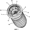
На фиг.3 представлено перспективное изображение зубного имплантата по фиг.1.Figure 3 presents a perspective image of the dental implant of figure 1.
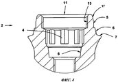
На фиг.4 на виде спереди, в разрезе и в увеличенном масштабе показана головка зубного имплантата по фиг.1.Figure 4 in front view, in section and on an enlarged scale shows the head of the dental implant of figure 1.
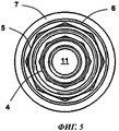
На фиг.5 зубной имплантат по фиг.1 показан на виде сверху.In Fig. 5, the dental implant of Fig. 1 is shown in plan view.
На фиг.6 на виде спереди показан второй вариант зубного имплантата.6, a second embodiment of a dental implant is shown in front view.
На фиг.7 на виде спереди, в разрезе и в увеличенном масштабе показана головка зубного имплантата по фиг.6.Figure 7 in front view, in section and on an enlarged scale shows the head of the dental implant of Fig.6.
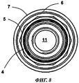
На фиг.8 зубной имплантат по фиг.6 показан на виде сверху.In Fig. 8, the dental implant of Fig. 6 is shown in plan view.
На фиг.9 на виде спереди показан третий вариант зубного имплантата.9, a third embodiment of a dental implant is shown in front view.
На фиг.10 на виде спереди, в разрезе и в увеличенном масштабе показана головка зубного имплантата по фиг.9.Figure 10 in front view, in section and on an enlarged scale shows the head of the dental implant of figure 9.
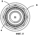
На фиг.11 зубной имплантат по фиг.9 показан на виде сверху. 11, the dental implant of FIG. 9 is shown in a plan view.
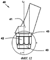
На фиг.12 на виде спереди показан наклонный каркас зубного протеза комплекта, состоящего из зубного имплантата, вспомогательной морфологической детали и протеза согласно изобретению.On Fig front view shows an inclined frame of the denture of the kit, consisting of a dental implant, an auxiliary morphological part and the prosthesis according to the invention.
На фиг.13 наклонный каркас по фиг.12 показан на виде снизу.In Fig.13, the inclined frame of Fig.12 is shown in a bottom view.
На фиг.14 наклонный каркас по фиг.12 показан на виде сверху.In Fig. 14, the inclined frame in Fig. 12 is shown in a plan view.
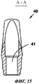
На фиг.15 наклонный каркас по фиг.12 показан в разрезе плоскостью А-А, обозначенной на фиг.12.In Fig. 15, the inclined frame in Fig. 12 is shown in section by the plane AA indicated in Fig. 12.
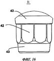
На фиг.16 в увеличенном масштабе показана зона В, обозначенная на фиг. 12.FIG. 16 shows, on an enlarged scale, the zone B indicated in FIG. 12.
На фиг.17 на виде спереди, с частичным вырезом представлена сборка зубного имплантата и протеза.On Fig in front view, with a partial cutaway presents the Assembly of the dental implant and prosthesis.
На фиг.18 сборка по фиг.17 показана в разрезе плоскостью А-А, обозначенной на фиг.17.In Fig. 18, the assembly in Fig. 17 is shown in section by the plane AA indicated in Fig. 17.
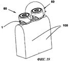
На фиг.19 в перспективном изображении показаны две сборки зубного имплантата и вспомогательной морфологической детали, установленные на челюстную кость.On Fig in a perspective image shows two assemblies of a dental implant and auxiliary morphological parts mounted on the jaw bone.
На фиг.20 в увеличенном масштабе показана зона В, обозначенная на фиг. 19.FIG. 20 shows, on an enlarged scale, the zone B indicated in FIG. 19.
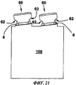
На фиг.21 сборки по фиг.19 показаны на виде сбоку.21, the assemblies of FIG. 19 are shown in side view.
Осуществление изобретенияThe implementation of the invention
Как показано на фиг.1-3, зубной имплантат 1 имеет, по существу, удлиненную цилиндрическую форму. У него имеется нижняя цилиндрическая часть 14 с наружной резьбовой поверхностью, охватывающей эту часть по всей ее длине и позволяющей закрепить эту часть в челюстной кости посредством ввинчивания.As shown in FIGS. 1-3, the
Над нижней частью 14 расположена часть 15 в форме усеченного конуса, поперечный размер которой увеличивается в направлении наружного конца имплантата. Соосно с ней расположены выступающий участок 7 в форме усеченного конуса и вторая часть 6, также в форме усеченного конуса. На конце имплантата соосно выполнена первая, призматическая концевая часть 5 с поперечным сечением в форме многоугольника. Применительно к имплантату по фиг.1-5 это сечение соответствует правильному восьмиугольнику, а для имплантата по фиг.6-8 - десятиугольнику.Above the
Кольцевой конический выступающий участок 7 имплантата 1 по фиг.1-8 соответствует области максимального диаметра (экватора) имплантата 1, отделяющей часть имплантата 1, которая находится внутри челюстной кости, от выступающей из кости части, которая будет частично закрыта тканью десны.The annular conical protruding
Как можно видеть из фиг.3, 5 и 8, кольцевой конический выступающий участок 7 полностью охватывает имплантат 1; его угол конусности составляет примерно 20°. Расположенный на боковой стороне имплантата, этот участок 7 обеспечивает лучшую опору для зубных протезов 9 (фиг.17, 18), каждый из которых состоит из устанавливаемого на имплантат каркаса 40 и фиксируемой на нем коронки, сформованной в виде зуба. Такая конструкция не подразумевает, что протез должен опираться по всей окружности выступающего участка 7: протез 9 может контактировать с данным участком 7 только в отдельных зонах. При этом зоны, не контактирующие с протезом, могут быть оптимизированы для биологического закрытия десной, которое может быть локализовано в зоне второй части 6 в форме усеченного конуса по завершении первого хирургического этапа.As can be seen from Figs. 3, 5 and 8, the annular conical protruding
Например, если зубной протез 9 замещает передний зуб (резец), протез 9 будет опираться на две диаметрально противоположные зоны верхней кольцевой поверхности выступающего участка 7 и/или на вторую часть 6 в форме усеченного конуса. При этом остальные зоны, которые не служат опорой, будут закрыты десной, образующей бугорки (десневые манжетки) на участках, не закрытых протезом 9.For example, if the
Если, как это имеет место в варианте по фиг.9, 10 и 11, имплантат 1 не содержит указанного выступающего участка 7, протез будет частично или полностью опираться на вторую часть 6 в форме усеченного конуса головки 2 имплантата 1. В данном варианте именно эта часть 6 будет определять экватор имплантата 1.If, as is the case in the embodiment of FIGS. 9, 10 and 11, the
Зубной имплантат 1 во всех своих вариантах является имплантатом с внутренним конусом, поскольку глухое осевое отверстие 11, выполненное со стороны его коронкового конца, имеет участок 3 в форме усеченного конуса. На фиг.2 показано, что у глухого осевого отверстия 11, у его закрытого конца, имеется также участок 12 с внутренней резьбой, предназначенный для приема зубного протеза 9, который рассчитан на прикрепление к головке 2 имплантата 1.
На фиг.2, 4 и 7 детально показано, что глухое осевое отверстие 11 содержит призматический участок 4, ограниченный участком 3 в форме усеченного конуса и выполненный с возможностью позиционирования и фиксации протеза 9 относительно имплантата 1. Участок 3 в форме усеченного конуса в глухом осевом отверстии 11 (именуемый также внутренним конусом) придает стабильность всем соединениям внутри имплантата 1, тем самым облегчая введение и фиксацию соединительной детали (абатмента) 50, расположенной между имплантатом 1 и каркасом 40 зубного протеза 9 (см. фиг.18).Figure 2, 4 and 7 shows in detail that the blind
Как вариант, участок 3 в форме усеченного конуса глухого осевого отверстия 11 может быть снабжен резьбой 13 на своем открытом конце, как в имплантате 1 по фиг.3 и 4. Альтернативно, в варианте по фиг.7 и 10 верхний конец участка 3 в форме усеченного конуса сохраняет свою форму, т.е. не имеет резьбы 13. Наличие внутренней резьбы 13 в верхней зоне имплантата 1 с внутренним конусом позволяет присоединять протезы 9, прикрепленные к каркасам, путем привинчивания с использованием соответствующей резьбы на их нижних концах. Тем самым обеспечивается немедленная иммобилизация каркаса относительно зубного имплантата 1, которая обычно выполняется винтом, проходящим через каркас и ввинчиваемым в участок с внутренней резьбой на конце глухого осевого отверстия 11. Каркасы 40 протезов могут состоять из деталей, установленных под углом (как это показано на фиг.12-16) или вертикально (см. фиг.17 и 18).Alternatively, the truncated cone shaped
Как уже упоминалось, из фиг.1, 2, 3, 4, 6, 7 и 9 можно видеть, что головка 2 имплантата 1 имеет первую, призматическую концевую часть 5, за которой расположена вторая часть 6 в форме усеченного конуса, охватывающая в радиальном направлении концевую часть 5 и образующая наружную опорную зону для зубного протеза 9 (см. фиг.18). Первая, призматическая концевая часть 5, наружный профиль которой соответствует многограннику, действующему как направляющая, обеспечивает позиционирование протеза 9 и предотвращает его поворот вокруг продольной оси имплантата 1.As already mentioned, from FIGS. 1, 2, 3, 4, 6, 7 and 9, it can be seen that the
Из фиг.1, 6, 9 и 10 можно видеть, что образующая второй части 6 в форме усеченного конуса формирует с осью имплантата 1 угол w, составляющий 10°-20°, предпочтительно 12°. Наличие этого угла стабилизирует протез 9, опирающийся на данную часть 6. Первая, призматическая концевая часть 5 расположена внутри конуса, являющегося продолжением второй части 6, как это наглядно показано для вариантов по фиг.4 и 7. При этом указанный угол w для части 6 совпадает с углом, который образуют участки 17, примыкающие к вертикальным участкам, формирующим стенки многогранника в составе призматической концевой части 5. Поскольку данная часть 5 находится в радиальном направлении внутри второй части 6 в форме усеченного конуса, она препятствует повороту любого протеза 9 после его установки.From figures 1, 6, 9 and 10 it can be seen that the generatrix of the
Предпочтительно призматический участок 4 глухого осевого отверстия 11 и первая, призматическая концевая часть 5 наружной поверхности головки 2 являются соосными призмами, основания которых являются схожими (однотипными) многоугольниками с взаимно параллельными сторонами, например шестиугольниками, восьмиугольниками (см. фиг.1-5), десятиугольниками (см. фиг.6-8), двенадцатиугольниками или любыми другими многоугольниками.Preferably, the
Каждая грань призматического участка 4, задаваемая соответствующей стороной базового многоугольника, задает определенное положение каркаса 40 протеза через соединительную деталь (абатмент) 50, которая вводится внутрь имплантата 1 с внутренним конусом, как это можно видеть на фиг.18.Each face of the
В другом типе каркаса 40 протеза имеется отверстие 41, через которое может быть проведен винт, фиксируемый ввинчиванием в участок с внутренней резьбой на закрытом конце глухого осевого отверстия 11. Такой вариант используется для наклонного каркаса 40 протеза, показанного на фиг.12-16. Как можно видеть на этих фигурах, нижняя половина наклонного каркаса 40 протеза содержит призматическую стенку 42, основание которой образовано многогранником с профилем, соответствующим профилю призматического участка 4 головки 2 имплантата 1. Таким образом, при ее введении внутрь призматического участка 4, сформированного в имплантате 1 с внутренним конусом, данная призматическая стенка 42 может быть установлена в столько различных положений, сколько имеется сторон у базового многоугольника. При этом будет предотвращен поворот установленного описанным образом каркаса 40 протеза относительно имплантата. Из фиг.12 и 16 можно видеть также, что призматическая стенка 42 заканчивается участком 43 в форме усеченного конуса, у которого угол конусности согласован с углом конусности участка 3 в форме усеченного конуса имплантата 1. В результате сопряжение между имплантатом 1 и наклонным каркасом 40 протеза обеспечивается сопряжением соответствующих конических участков внутри имплантата.In another type of
Призматический участок 4 глухого осевого отверстия 11, окруженный конусным участком 3, используется для ввинчивания имплантата 1 в челюстную кость, а также для позиционирования протезов, которые по своей конструкции должны занимать определенное положение, например наклонных протезов или протезов, сформованных определенным образом. Кроме того, данный участок 4 служит для задания профиля и размеров зубного протеза 9, что позволяет протезисту изготовить нужный протез.The
В случае отсутствия внутреннего призматического или иного некруглого участка, дополняющего внутренний конус, в сочетании с соответствующей формацией на протезе 9, предназначенном для реконструкции одиночного зуба, чтобы предотвратить поворот протеза, было бы необходимо использовать деталь, входящую внутрь полости имплантата, как это имело место с традиционными имплантатами, имеющими конический профиль или внутреннюю полость.In the absence of an internal prismatic or other non-circular section complementary to the inner cone, in combination with the corresponding formation on the
Аналогично, каждая из поверхностей призматической концевой части 5 задает конкретное положение протеза 9 на каркасе.Similarly, each of the surfaces of the
Таким образом, благодаря комбинированию внутренней и наружной многоугольных конфигураций в виде призматического участка 4 и первой, наружной призматической концевой части 5 соответственно расширяются возможности использования внутреннего конуса для позиционирования и фиксации ориентации протеза 9 относительно имплантата 1, а также возможности применения оптимальных деталей в каждом конкретном случае протезирования. Кроме того, облегчается коррекция любых расхождений между осью введения в имплантат 1 и осью, задаваемой протезом 9.Thus, by combining the inner and outer polygonal configurations in the form of a
На фиг.17 показана сборка, состоящая из зубного имплантата 1 и протеза 9. Входящий в сборку протез 9 сконструирован таким образом, что его конец опирается, по меньшей мере, на две диаметрально противоположные зоны второй части 6 в форме усеченного конуса и/или на кольцевой выступающий участок 7 в форме усеченного конуса имплантата (см. фиг.4, 7 и 10).17 shows an assembly consisting of a
Как уже упоминалось, кольцевой выступающий участок 7 в форме усеченного конуса предназначен служить опорой для зубного протеза 9. Данный участок 7 слегка смещен относительно части 15 в форме усеченного конуса, которая введена в костную ткань, и это позволяет концу протеза опираться на выступающий участок 7, не выступая в поперечном направлении за предельный поперечный размер указанной часть 15. Таким образом, даже при работе с протезами 9, формируемыми отливкой, когда точность размеров не столь высока, протез 9 будет надежно опираться на головку 2 имплантата 1, как это показано на фиг.18.As already mentioned, the annular protruding
Зубной имплантат 1 может формировать часть комплекта, состоящего из данного имплантата, зубного протеза 9 и вспомогательной морфологической детали 60. Все названные элементы могут соединяться друг с другом, чтобы сформировать зуб с полными гарантиями и без каких-либо проблем, связанных с тем, что имплантат и устанавливаемый на место зуба протез 9 не будут стыковаться.
Далее, со ссылками на фиг.19-21 будет дано краткое пояснение операций, выполняемых при реставрации зуба, включающей постановку зубного имплантата 1 согласно изобретению, начиная с ситуации, когда дефектный зуб был полностью удален.Next, with reference to FIGS. 19-21, a brief explanation will be given of the operations performed during tooth restoration, including the placement of the
Сначала хирург-стоматолог устанавливает в костную ткань зубной имплантат 1 таким образом, что нижний край кольцевого выступающего участка 7 в форме усеченного конуса образует экватор, который разделяет выступающую часть имплантата 1 и его часть, которая введена в челюстную кость и десну 100, закрывающую верхнюю часть данной кости.First, the dental surgeon places a
Чтобы добиться желательного здорового и эстетичного вида, на головку 2 имплантата 1 устанавливают вспомогательную морфологическую деталь 60, аналогичную колпачку. В верхней поверхности этой детали 60 имеется глухое осевое отверстие 63 с поперечным сечением в форме многоугольника, в которое может быть введен инструмент типа отвертки с целью прикрепления детали 60 к головке 2 имплантата 1. Возможность такого прикрепления обеспечивается наличием внутри морфологической детали 60 втулки с наружной резьбой, соответствующей участку с внутренней резьбой 13 на открытом конце внутреннего конуса имплантата 1.To achieve the desired healthy and aesthetic appearance, an auxiliary
Следует отметить, что нижний конец морфологической детали 60 опирается на вторую часть 6 в форме усеченного конуса и на кольцевой выступающий участок 7 в форме усеченного конуса головки 2 имплантата 1, поскольку этот нижний конец имеет форму усеченного конуса 66, соответствующего усеченному конусу части 6, за которой следует концевой участок 67 в форме усеченного конуса, соответствующий по форме выступающему участку 7.It should be noted that the lower end of the
Как показано на фиг.19-21, вспомогательная морфологическая деталь 60 снабжена двумя диаметрально противоположными отверстиями 62 криволинейного профиля, предназначенными для того, чтобы открыть некоторые зоны головки 2 имплантата 1, которые должны быть закрыты тканью десны 100. Благодаря такому выполнению через некоторое время после прикрепления морфологических деталей 60 к имплантатам 1 биологическая ткань десны 100 займет те участки головки 2 имплантата 1, которые были оставлены открытыми.As shown in Figs. 19-21, the auxiliary
По истечении этого времени, когда морфологические детали 60 будут удалены, станет заметно, что верхний край десны 100 сформировал криволинейные участки, заданные профилем отверстий 62. Именно в этот момент производится установка зубного протеза 9, содержащего каркас 40 (на котором закреплена коронка 70, имеющая форму зуба). Нижний конец протеза 9 будет аналогичен вспомогательной морфологической детали 60, т.е. он будет иметь участок 46 в форме усеченного конуса, соответствующий участку 6, за которым следует концевой участок 47 в форме усеченного конуса, соответствующий по форме и размерам выступающему участку 7. При этом протез будет иметь отверстия, идентичные по форме и положению относительно имплантата 1 отверстиям 62 во вспомогательной морфологической детали 60.After this time, when the
Поэтому после установки протеза 9 вся боковая поверхность головки 2 имплантата 1 будет закрыта в определенных зонах протезом 9, а в остальной части десной 100, которая образует соответствующие бугорки (манжетки) между зубами, что будет являться несомненным свидетельством здоровых зубов.Therefore, after installing the
Следует также отметить, что, хотя на фиг.19-21 показаны два отверстия 62 на нижних концах морфологических вспомогательных деталей 60, в зависимости от типа замещаемого зуба, необходимо обеспечить определенную форму бугорков, формируемых десной 100, в связи с чем могут потребоваться другое количество и другой профиль отверстий 62.It should also be noted that, although FIGS. 19-21 show two
Claims (8)
Applications Claiming Priority (2)
| Application Number | Priority Date | Filing Date | Title |
|---|---|---|---|
| ES200601408A ES2315100B1 (en) | 2006-05-23 | 2006-05-23 | DENTAL IMPLANT OF INTERNAL CONE. |
| ESP200601408 | 2006-05-23 |
Publications (2)
| Publication Number | Publication Date |
|---|---|
| RU2008148800A RU2008148800A (en) | 2010-06-27 |
| RU2440061C2 true RU2440061C2 (en) | 2012-01-20 |
Family
ID=38197826
Family Applications (1)
| Application Number | Title | Priority Date | Filing Date |
|---|---|---|---|
| RU2008148800/14A RU2440061C2 (en) | 2006-05-23 | 2007-04-25 | Dental implant with internal cone |
Country Status (6)
| Country | Link |
|---|---|
| US (1) | US20100143869A1 (en) |
| EP (1) | EP2023848A1 (en) |
| CA (1) | CA2650411A1 (en) |
| ES (1) | ES2315100B1 (en) |
| RU (1) | RU2440061C2 (en) |
| WO (1) | WO2007134686A1 (en) |
Families Citing this family (9)
| Publication number | Priority date | Publication date | Assignee | Title |
|---|---|---|---|---|
| US9314318B2 (en) * | 2008-08-26 | 2016-04-19 | Zest Ip Holdings, Llc | Dental anchor apparatus and method |
| US10350033B2 (en) * | 2009-08-26 | 2019-07-16 | Straumann Holding Ag | Dental implant and kit including said dental implant |
| EP2347729A1 (en) | 2010-01-21 | 2011-07-27 | Camlog Biotechnologies AG | Dental implant, abutment for a dental implant, combination of the same and an implantation set |
| KR101134342B1 (en) * | 2010-04-22 | 2012-04-09 | 주식회사 메가젠임플란트 | Dental implant fixture and implant set having the same |
| CH707689A1 (en) * | 2013-03-08 | 2014-09-15 | Dentalpoint Ag | Zahnimplatat. |
| US9629696B2 (en) * | 2013-06-07 | 2017-04-25 | Paul Ouellette | Hybrid temporary anchorage device implant system and associated methods |
| KR101388846B1 (en) * | 2013-09-10 | 2014-04-23 | 왕제원 | One body implant |
| IL230833A0 (en) * | 2014-02-05 | 2014-09-30 | Ophir Fromovich | Bone implant anchor |
| JP6939079B2 (en) * | 2017-05-16 | 2021-09-22 | 日本電産株式会社 | Motor and disk drive |
Family Cites Families (26)
| Publication number | Priority date | Publication date | Assignee | Title |
|---|---|---|---|---|
| DE3421056A1 (en) * | 1984-06-06 | 1985-12-12 | Feldmühle AG, 4000 Düsseldorf | JAW IMPLANT FOR THE ADMISSION OF A DENTAL SPARE CARRIER |
| US4856994A (en) * | 1988-01-25 | 1989-08-15 | Implant Innovations, Inc. | Periodontal restoration components |
| US5030095A (en) * | 1989-08-16 | 1991-07-09 | Niznick Gerald A | Angled abutment for endosseous implants |
| US5169309A (en) * | 1990-01-12 | 1992-12-08 | Attachments International, Inc. | Abutment for dental appliances and the like |
| US5376004A (en) * | 1993-11-18 | 1994-12-27 | Mena; Raul | Dental implant device |
| US5622500A (en) * | 1994-02-24 | 1997-04-22 | Core-Vent Corporation | Insertion tool/healing collar/abutment |
| DE9420038U1 (en) * | 1994-12-14 | 1995-02-09 | Hartmann Alexander | Implant device |
| BR9610906A (en) * | 1995-10-13 | 1999-07-13 | Straumann Inst Ag | Connection device between an implant and a counter-support |
| SE512050C2 (en) * | 1997-01-21 | 2000-01-17 | Nobel Biocare Ab | Rotationally symmetrical leg anchoring element |
| US6168435B1 (en) * | 1998-10-26 | 2001-01-02 | Implant Innovations, Inc. | Ceramic dental abutments with a metallic core |
| SE513111C2 (en) * | 1998-11-11 | 2000-07-10 | Nobel Biocare Ab | Threaded implant and device and method for such an implant |
| US6663388B1 (en) * | 1998-12-28 | 2003-12-16 | Institut Straumann Ag | Connection between a dental implant and an abutment |
| IT1307923B1 (en) * | 1999-01-25 | 2001-11-29 | Hofmann S A S Di Roberto Hofma | ENDOSSEO DENTAL IMPLANT DEVICE. |
| IT1311004B1 (en) * | 1999-03-16 | 2002-02-27 | Antonio Gallicchio | IMPLANT FOR ARTIFICIAL TEETH. |
| US6287117B1 (en) * | 1999-04-22 | 2001-09-11 | Sulzer Dental Inc. | Endosseous dental implants including a healing screw and an optional implant extender |
| WO2001012054A2 (en) * | 1999-08-17 | 2001-02-22 | Pioneer Laboratories | Bone connector system |
| ES1044251Y (en) * | 1999-10-06 | 2000-09-01 | Soadco S L | DENTAL IMPLANT. |
| DE10315399A1 (en) * | 2003-02-21 | 2004-09-02 | Schröder, Ralf, Dr. | Dental implant with base body and implant post as well as base body and implant post for a dental implant |
| WO2004073541A2 (en) * | 2003-02-21 | 2004-09-02 | Schroeder Ralf | Dental implant comprising a base body and implant post and corresponding base body and implant post |
| FR2854789B1 (en) * | 2003-05-12 | 2006-03-17 | Martin Paul Koury | DEFINITIVE MONOBLOC CORONORADICULAR DENTAL IMPLANT |
| DE10329207A1 (en) * | 2003-06-28 | 2005-01-13 | Ralf Dr. Schröder | Basic body for a dental implant, dental implant with basic body, implant post of a dental implant for introduction into the main body, dental implant with basic body and implant post and crown body for the implant post or the dental implant and packaging for dental implant |
| EP1659973A4 (en) * | 2003-08-11 | 2007-10-03 | Imtec Corp | Dental implant system |
| US20060194171A1 (en) * | 2003-10-03 | 2006-08-31 | Sargon Lazarof | Bi-polar implant |
| US7249949B2 (en) * | 2004-06-29 | 2007-07-31 | Lifecore Biomedical, Inc. | Internal connection dental implant |
| US20060003290A1 (en) * | 2004-07-01 | 2006-01-05 | Niznick Gerald A | Endosseous one-piece screw-type dental implants |
| USD603514S1 (en) * | 2008-07-09 | 2009-11-03 | Silvio Franco Emanuelli | Dental implant |
-
2006
- 2006-05-23 ES ES200601408A patent/ES2315100B1/en not_active Expired - Fee Related
-
2007
- 2007-04-25 WO PCT/EP2007/003629 patent/WO2007134686A1/en active Application Filing
- 2007-04-25 RU RU2008148800/14A patent/RU2440061C2/en not_active IP Right Cessation
- 2007-04-25 EP EP07724559A patent/EP2023848A1/en not_active Withdrawn
- 2007-04-25 CA CA002650411A patent/CA2650411A1/en not_active Abandoned
- 2007-04-25 US US12/301,911 patent/US20100143869A1/en not_active Abandoned
Also Published As
| Publication number | Publication date |
|---|---|
| US20100143869A1 (en) | 2010-06-10 |
| ES2315100B1 (en) | 2010-01-05 |
| ES2315100A1 (en) | 2009-03-16 |
| RU2008148800A (en) | 2010-06-27 |
| WO2007134686A1 (en) | 2007-11-29 |
| EP2023848A1 (en) | 2009-02-18 |
| CA2650411A1 (en) | 2007-11-29 |
Similar Documents
| Publication | Publication Date | Title |
|---|---|---|
| RU2440061C2 (en) | Dental implant with internal cone | |
| KR101881421B1 (en) | Abutment assembly | |
| KR102278335B1 (en) | Abutment system and dental methods | |
| US7014464B2 (en) | Multi-part abutment and transfer cap for use with an endosseous dental implant with non-circular, beveled implant/abutment interface | |
| KR100484395B1 (en) | Structure of dental implant | |
| US20080227057A1 (en) | Narrow Dental Implant and Associated Parts | |
| EP0473262A1 (en) | Dental implant collar and post system | |
| EP1021996B1 (en) | Device for an endosteal dental implant | |
| RU2402992C2 (en) | Dental implant system and method for implantation and making implant system | |
| CA2600280A1 (en) | Screw-in enossal dental implant | |
| RU2100981C1 (en) | Enosseous implant of single tooth | |
| KR20200014558A (en) | Abutment assembly | |
| WO2019017813A1 (en) | Dental implant, connecting screw and kit for implantation | |
| KR101524192B1 (en) | Cervical Shape Abutment for Dental Implant | |
| US20180280121A1 (en) | Dental implant systems and methods of implantation | |
| RU2720486C2 (en) | Kit for dental implantation comprising dental implant and prosthetic components designed to fix single denture in upper and lower jaws of patient | |
| KR102597778B1 (en) | Dental abutment system | |
| KR20070119628A (en) | Narrow dental implant and associated pieces | |
| KR200286847Y1 (en) | Structure of dental implant | |
| KR102194250B1 (en) | Dental Implant Abutment Assembly | |
| KR102500193B1 (en) | A dual fixation system for prosthetics on dental implants that allows the prosthesis to be properly screwed or clipped. | |
| KR101091588B1 (en) | Dental implant fixture | |
| KR20230044765A (en) | Dental abutment system having cement-free crown | |
| KR20230162851A (en) | Abutment Assembly for Dental Implants | |
| IT9019652A1 (en) | DENTAL PROSTHESIS IMPLANT COMPLEX CONSISTING OF AN OSTEO-INTEGRATED SCREW AND A FIXABLE ABUTMENT |
Legal Events
| Date | Code | Title | Description |
|---|---|---|---|
| TK4A | Correction to the publication in the bulletin (patent) |
Free format text: AMENDMENT TO CHAPTER -FG4A- IN JOURNAL: 2-2012 FOR TAG: (73) |
|
| MM4A | The patent is invalid due to non-payment of fees |
Effective date: 20140426 |