RU2435966C2 - Method and system of start and operation of electrically driven load - Google Patents
Method and system of start and operation of electrically driven load Download PDFInfo
- Publication number
- RU2435966C2 RU2435966C2 RU2009113662A RU2009113662A RU2435966C2 RU 2435966 C2 RU2435966 C2 RU 2435966C2 RU 2009113662 A RU2009113662 A RU 2009113662A RU 2009113662 A RU2009113662 A RU 2009113662A RU 2435966 C2 RU2435966 C2 RU 2435966C2
- Authority
- RU
- Russia
- Prior art keywords
- electric machine
- electric
- power supply
- speed
- supply network
- Prior art date
Links
Images
Classifications
-
- H—ELECTRICITY
- H02—GENERATION; CONVERSION OR DISTRIBUTION OF ELECTRIC POWER
- H02P—CONTROL OR REGULATION OF ELECTRIC MOTORS, ELECTRIC GENERATORS OR DYNAMO-ELECTRIC CONVERTERS; CONTROLLING TRANSFORMERS, REACTORS OR CHOKE COILS
- H02P1/00—Arrangements for starting electric motors or dynamo-electric converters
- H02P1/16—Arrangements for starting electric motors or dynamo-electric converters for starting dynamo-electric motors or dynamo-electric converters
- H02P1/26—Arrangements for starting electric motors or dynamo-electric converters for starting dynamo-electric motors or dynamo-electric converters for starting an individual polyphase induction motor
-
- F—MECHANICAL ENGINEERING; LIGHTING; HEATING; WEAPONS; BLASTING
- F01—MACHINES OR ENGINES IN GENERAL; ENGINE PLANTS IN GENERAL; STEAM ENGINES
- F01D—NON-POSITIVE DISPLACEMENT MACHINES OR ENGINES, e.g. STEAM TURBINES
- F01D15/00—Adaptations of machines or engines for special use; Combinations of engines with devices driven thereby
- F01D15/10—Adaptations for driving, or combinations with, electric generators
-
- F—MECHANICAL ENGINEERING; LIGHTING; HEATING; WEAPONS; BLASTING
- F05—INDEXING SCHEMES RELATING TO ENGINES OR PUMPS IN VARIOUS SUBCLASSES OF CLASSES F01-F04
- F05D—INDEXING SCHEME FOR ASPECTS RELATING TO NON-POSITIVE-DISPLACEMENT MACHINES OR ENGINES, GAS-TURBINES OR JET-PROPULSION PLANTS
- F05D2220/00—Application
- F05D2220/70—Application in combination with
- F05D2220/76—Application in combination with an electrical generator
-
- F—MECHANICAL ENGINEERING; LIGHTING; HEATING; WEAPONS; BLASTING
- F05—INDEXING SCHEMES RELATING TO ENGINES OR PUMPS IN VARIOUS SUBCLASSES OF CLASSES F01-F04
- F05D—INDEXING SCHEME FOR ASPECTS RELATING TO NON-POSITIVE-DISPLACEMENT MACHINES OR ENGINES, GAS-TURBINES OR JET-PROPULSION PLANTS
- F05D2260/00—Function
- F05D2260/85—Starting
Landscapes
- Engineering & Computer Science (AREA)
- Power Engineering (AREA)
- Mechanical Engineering (AREA)
- General Engineering & Computer Science (AREA)
- Control Of Eletrric Generators (AREA)
- Control Of Turbines (AREA)
- Control Of Multiple Motors (AREA)
- Motor And Converter Starters (AREA)
- Control Of Positive-Displacement Pumps (AREA)
Abstract
Description
Область изобретенияField of Invention
В целом, настоящее изобретение относится к мощным электрическим приводам с нерегулируемой скоростью, прежде всего, к приводам с мощностью от 10 МВт и более. При использовании в подводных условиях изобретение может быть использовано в приводах любой мощности (а также в оборудовании с уменьшенным потреблением энергии, например, питающемся от маломощной системы энергоснабжения). Настоящее изобретение применимо, в частности, для мощных и сверхмощных приводов газовых компрессоров и для приводов насосов, но может быть использовано для работы других типов сверхмощного оборудования различного назначения. Оно особенно подходит для рабочего оборудования для переработки природного газа, например, при производстве сжиженного природного газа на заводах по сжижению природного газа, на которых компрессоры для сжижения природного газа приводятся в действие электрическим приводом.In General, the present invention relates to powerful electric drives with unregulated speed, primarily to drives with a capacity of 10 MW or more. When used underwater conditions, the invention can be used in drives of any power (as well as equipment with reduced energy consumption, for example, powered by a low-power power supply system). The present invention is applicable, in particular, for powerful and heavy duty drives of gas compressors and for pump drives, but can be used to operate other types of heavy duty equipment for various purposes. It is particularly suitable for working equipment for processing natural gas, for example, in the production of liquefied natural gas in natural gas liquefaction plants, in which compressors for liquefying natural gas are electrically driven.
Предпосылки к созданию и уровень техникиPrerequisites for the creation and prior art
Имеющие отношение к нефтегазовой отрасли устройства часто включают в себя мощные приводы насосов и/или компрессоров, которые разработаны для использования в экономичных конструкциях, запуска и работы в различных условиях. Примером такого проекта может быть завод по сжижению природного газа.Devices related to the oil and gas industry often include powerful pump and / or compressor drives that are designed to be used in economical designs, to run and operate in a variety of conditions. An example of such a project would be a natural gas liquefaction plant.
Сжиженный природный газ (Liquefied Natural Gas) является продуктом охлаждения природного газа до температуры, при которой природный газ становится жидкостью. Природный газ может транспортироваться в больших объемах в сжиженном состоянии экономичным способом, в частности, в тех случаях, когда трубопроводы недоступны или слишком дороги, или требуется много времени для их прокладки. Обычно, танкеры для сжиженного природного газа перевозят большие объемы природного газа по морю от места его производства до места потребления или временного хранения.Liquefied Natural Gas (Liquefied Natural Gas) is a product of cooling natural gas to a temperature at which natural gas becomes liquid. Natural gas can be transported in large volumes in a liquefied state in an economical way, in particular in cases where pipelines are unavailable or too expensive, or it takes a long time to lay them. Typically, liquefied natural gas tankers transport large volumes of natural gas by sea from the place of production to the place of consumption or temporary storage.
В международной патентной заявке WO 97/33131 описана установка для производства сжиженного природного газа, в которой основные ступени охлаждения механически взаимосвязаны и скомпонованы для привода в действие от единой общей газовой турбины, при этом для запуска газовой турбины установлен вспомогательный двигатель. Недостатками механически взаимосвязанных приводящих и приводимых агрегатов установки являются, среди прочего, длинная кинематическая цепь вращающихся на общем валу машин, которая занимает много места и требует тщательной балансировки вала, а также то, что приводимые и приводящие агрегаты необходимо располагать близко друг к другу.International patent application WO 97/33131 describes a plant for the production of liquefied natural gas, in which the main cooling stages are mechanically interconnected and arranged to drive from a single common gas turbine, while an auxiliary engine is installed to start the gas turbine. The disadvantages of mechanically interconnected drive and driven units of the installation are, inter alia, the long kinematic chain of machines rotating on a common shaft, which takes up a lot of space and requires careful balancing of the shaft, as well as the fact that the driven and driven units must be located close to each other.
В настоящее время производство сжиженного природного газа часто основано на применении газовых или паровых турбин для обеспечения подачи электроэнергии на привод используемых при сжижении природного газа охлаждающих агрегатов. Например, в международной патентной заявке WO 2005/047789 А2 описана система привода для производства сжиженного природного газа, в которой холодильный компрессор приводится в действие газовой турбиной, соединенной с пусковым электродвигателем через общий приводной вал между газовой турбиной и компрессором.Currently, the production of liquefied natural gas is often based on the use of gas or steam turbines to provide power to the drive used in the cooling units used for liquefying natural gas. For example, international patent application WO 2005/047789 A2 describes a drive system for producing liquefied natural gas in which a refrigeration compressor is driven by a gas turbine connected to a starting motor through a common drive shaft between the gas turbine and the compressor.
Расположенные в относительной близости к компрессору приводы компрессоров на основе газовой турбины в качестве механического привода представляют собой источники опасности в связи с тем, что система для сжигания газа, обычно работающая при довольно высокой температуре, установлена на заводе по сжижению природного газа достаточно близко к холодильному компрессору. Кроме того, газовая турбина обычно вырабатывает некоторое количество отработанных газов, которые следует так или иначе принимать во внимание, чтобы свести к минимуму риски на заводе по переработке природного газа. Для всех, кто связан с проектированием или эксплуатацией заводов по сжижению природного газа на берегу, в море или где угодно, должно быть ясно, что расположенные поблизости газовые горелки и истечение горячих отработанных газов вблизи от опасной зоны не являются удачным решением, и, вероятно, наиболее привлекательным было бы другое решение, которое также может улучшить беспрерывность производства. Очевидным альтернативным предложением является частотно-управляемый электропривод, который также должен использоваться в различных сочетаниях с турбинными приводами. Завод, находящийся под управлением компании «Statoil» в городе Хаммерфест (Hammerfest) в Норвегии, представляет собой пример завода по сжижению природного газа, с использованием частотного регулирования.Gas turbine-based compressor drives located in relative proximity to the compressor as a mechanical drive are a source of danger due to the fact that the gas combustion system, which usually operates at a rather high temperature, is installed in the natural gas liquefaction plant quite close to the refrigeration compressor . In addition, a gas turbine usually produces a certain amount of exhaust gas, which should be taken into account in one way or another in order to minimize the risks at the natural gas processing plant. It should be clear to anyone involved in the design or operation of natural gas liquefaction plants onshore, at sea or elsewhere that nearby gas burners and the expiration of hot exhaust gases near a hazardous area are not a good solution, and probably another solution would be most attractive, which could also improve production continuity. An obvious alternative is a frequency-controlled electric drive, which should also be used in various combinations with turbine drives. The Statoil plant in Hammerfest, Norway, is an example of a natural gas liquefaction plant using frequency regulation.
В патентной публикации US 5,689,141 описывается система привода компрессора для завода по сжижению природного газа, имеющая поддерживающий преобразователем частоты пуск путем разгона газовой турбины до ram-скорости и воспламенения. В процессе обычной эксплуатации при постоянной скорости электрический двигатель работает в качестве генератора для преобразования вырабатываемой газовой турбиной избыточной механической мощности в электрическую энергию и передачи этой электрической энергии на основной источник электрической мощности на заводе. В этом случае газовая турбина и компрессор смонтированы на общем валу.US Pat. No. 5,689,141 describes a compressor drive system for a natural gas liquefaction plant having a frequency converter starting by accelerating a gas turbine to ram speed and ignition. During normal operation at constant speed, the electric motor acts as a generator to convert the excess mechanical power generated by the gas turbine into electrical energy and transfer this electrical energy to the main source of electrical power at the plant. In this case, the gas turbine and compressor are mounted on a common shaft.
Преобразователь частоты представляет собой достаточно крупный элемент оборудования. Чтобы передать мощность порядка 50 МВт, преобразователь частоты мог бы заполнить четырех- или пятиэтажное здание площадью около 1000 м2. Несмотря на размеры и стоимость таких преобразователей частоты, они зачастую рассматриваются в качестве необходимого оборудования при передаче электрической мощности между приводящими и приводимыми агрегатами, если передаваемая мощность находится в диапазоне порядка 10 МВт или более.The frequency converter is a fairly large piece of equipment. To transmit power of the order of 50 MW, the frequency converter could fill a four- or five-story building with an area of about 1000 m 2 . Despite the size and cost of such frequency converters, they are often considered as necessary equipment when transmitting electric power between driving and driven units, if the transmitted power is in the range of about 10 MW or more.
В патентной заявке US 6,640,586 В1 описана технологическая система для сжижения природного газа, использующая механические приводы и электрические двигатели в качестве приводов компрессора. Описываются различные сочетания компрессоров и электрических двигателей, используемые для различных типов охлаждающих веществ. В этой публикации содержатся краткие описания нескольких недостатков использования обычных газовых турбин на заводах по сжижению природного газа и описываются различные способы сочетания компрессоров и электродвигателей для привода в действие компрессоров на заводах по сжижению природного газа. Электродвигатели в этих технических решениях зачастую используются для запуска посредством различных способов и, по возможности, для содействия газовой турбине в процессе нормальной работы, а механически приводимая в действие кинематическая цепь иногда содержит также паровые турбины.US Pat. No. 6,640,586 B1 describes a process system for liquefying natural gas using mechanical drives and electric motors as compressor drives. The various combinations of compressors and electric motors used for various types of coolants are described. This publication provides brief descriptions of several of the disadvantages of using conventional gas turbines in natural gas liquefaction plants and describes various methods of combining compressors and electric motors to drive compressors in natural gas liquefaction plants. Electric motors in these technical solutions are often used to start by various methods and, if possible, to assist the gas turbine during normal operation, and the mechanically driven kinematic chain sometimes also contains steam turbines.
Принимая во внимание вышеописанный известный уровень техники и недостатки, отмеченные у ближайших аналогов, желательно разработать новые и изобретательские решения, которые смогут преодолеть один или несколько из вышеперечисленных недостатков, достигая оптимальную функциональность в системе привода компрессора для завода по сжижению природного газа или для других целей.Considering the above-described prior art and the disadvantages noted by the closest analogues, it is desirable to develop new and inventive solutions that can overcome one or more of the above disadvantages, achieving optimal functionality in the compressor drive system for a natural gas liquefaction plant or for other purposes.
Цель изобретенияThe purpose of the invention
Главной целью настоящего изобретения является создание системы силового привода, например, для компрессора или насоса, в которой необходимость в дорогостоящем и крупногабаритном частотном преобразователе значительно уменьшена. Тем самым, будет уменьшена стоимость, вес и объем всей системы, что, в свою очередь, уменьшит сложность эксплуатации и проектирования завода.The main objective of the present invention is to provide a power drive system, for example, for a compressor or pump, in which the need for an expensive and large-sized frequency converter is significantly reduced. Thus, the cost, weight and volume of the entire system will be reduced, which, in turn, will reduce the complexity of operation and design of the plant.
Другой целью настоящего изобретения является создание системы привода для главной нагрузки, например для компрессора или насоса, которая может быть использована для перерабатывающего завода, прежде всего, для завода по сжижению природного газа, а также для уменьшения стоимости резервных агрегатов и запасных частей для резервных целей.Another objective of the present invention is to provide a drive system for the main load, for example for a compressor or pump, which can be used for a processing plant, especially for a plant for liquefying natural gas, as well as to reduce the cost of spare units and spare parts for reserve purposes.
Следующей дополнительной целью настоящего изобретения является создание новой компоновки привода компрессора или насоса, прежде всего, для завода по переработке нефти и/или природного газа, в которой является нецелесообразным соединение газовой или паровой турбины с механическим валом компрессора или насоса для привода его в действие, например, в замкнутых пространствах, где предпочтительна лишь компоновка электрического привода.A further additional object of the present invention is to provide a new compressor or pump drive arrangement, especially for an oil and / or natural gas refinery, in which it is not practical to connect a gas or steam turbine to the mechanical shaft of the compressor or pump to drive it, for example , in confined spaces where only an electric drive arrangement is preferred.
Следующей дополнительной целью настоящего изобретения является создание новой компоновки привода, предназначенной для применений, в которых она может обеспечить связь на удалении, что зачастую препятствует использованию способов плавного пуска или прямого старта, характерного для работы привода с нерегулируемой скоростью. Типичными примерами могут быть удаленные расположения привода, которые могут быть совершенно недоступны, прежде всего, если они находятся в подводном положении.A further additional objective of the present invention is to provide a new drive arrangement intended for applications in which it can provide remote communication, which often prevents the use of soft start or direct start methods specific to operating the drive at an unregulated speed. Typical examples are remote drive locations that may be completely inaccessible, especially if they are underwater.
Следующей дополнительной целью настоящего изобретения является создание новой компоновки привода, предназначенной для изменяемого соотнесения генератора с электродвигателем, для обеспечения возможности пуска и работы различных сочетаний электродвигателей и генераторов совершенно независимо друг от друга и на сосуществующих электроэнергетических системах. Кроме того, цель изобретения состоит в обеспечении работы сосуществующих энергосистем, частично независимых друг от друга, то есть в изолированном режиме, с совершенно свободно выбираемой частотой в каждой энергосистеме, которая работает в изолированном режиме. Для этого, использование различных принципов преобразования электрической энергии могло бы сделать возможным обмен электрической энергии для улучшения диапазона выработки электроэнергии в каждой из энергосистем, работающих в изолированном режиме.A further additional objective of the present invention is the creation of a new drive arrangement, designed for variable correlation of the generator with the electric motor, to enable the start-up and operation of various combinations of electric motors and generators completely independently of each other and on coexisting electric power systems. In addition, the purpose of the invention is to ensure the operation of coexisting power systems, partially independent of each other, that is, in an isolated mode, with a completely freely selectable frequency in each power system that operates in an isolated mode. For this, the use of various principles of electric energy conversion could make it possible to exchange electric energy to improve the range of electricity generation in each of the energy systems operating in an isolated mode.
Краткое изложение существа изобретенияSummary of the invention
В первом аспекте изобретения предлагается способ пуска и работы электрически приводимой в действие нагрузки, например компрессора (1) или насоса, путем подвода энергии от механического привода, например турбины или двигателя внутреннего сгорания, посредством чего нагрузка механически подсоединятся к первой электрической машине, а названный механический привод механически присоединен ко второй электрической машине, отличающийся тем, чтоIn a first aspect of the invention, there is provided a method of starting and operating an electrically driven load, such as a compressor (1) or a pump, by supplying energy from a mechanical drive, such as a turbine or internal combustion engine, whereby the load is mechanically connected to the first electric machine, and the mechanical the drive is mechanically attached to a second electrical machine, characterized in that
1) электрическое соединение первой электрической машины ко второй электрической машине осуществляется в неподвижном состоянии или когда первая и вторая машины имеют низкую скорость вращения;1) the electrical connection of the first electric machine to the second electric machine is carried out in a stationary state or when the first and second machines have a low rotation speed;
2) в фазе разгона ускорение первой электрической машины осуществляется ускорением второй электрической машины с механическим приводом;2) in the acceleration phase, the acceleration of the first electric machine is carried out by the acceleration of the second electric machine with a mechanical drive;
3) если первая электрическая машина достигла предварительно заданной скорости вращения, осуществляется синхронизация ее с локальной сетью электроснабжения и подключение ее к этой сети. Благодаря этому способу становятся возможными запуск и привод в действие первой электрической машины в любое время вне зависимости от наличия частотного преобразователя между генератором и электродвигателем.3) if the first electric machine has reached a predetermined rotation speed, it is synchronized with a local power supply network and connected to this network. Thanks to this method, it is possible to start and drive the first electric machine at any time, regardless of the presence of a frequency converter between the generator and the electric motor.
Во втором аспекте изобретения предлагается способ запуска и работы электрически приводимой в действие нагрузки, например компрессора (1) или насоса, которая приводится в действие первой электрической машиной путем подачи энергии от механического привода, такого как турбина или двигатель внутреннего сгорания, или от частотного преобразователя, получающего энергию от внешней сети энергоснабжения, или от местного источника, такого как механический привод,In a second aspect of the invention, there is provided a method of starting and operating an electrically driven load, such as a compressor (1) or a pump, which is driven by a first electric machine by supplying energy from a mechanical drive, such as a turbine or internal combustion engine, or from a frequency converter, receiving energy from an external power supply network, or from a local source, such as a mechanical drive,
отличающийся тем, чтоcharacterized in that
1) в фазе ускорения разгон первой электрической машины, такой как электродвигатель, для названной нагрузки осуществляется от нулевой, близкой к нулевой, или малой скорости посредством либо1) in the acceleration phase, the acceleration of the first electric machine, such as an electric motor, for the named load is carried out from zero, close to zero, or low speed by means of either
a) разгона второй электрической машины, соединенной с механическим приводом, при этом вторая электрическая машина электрически подключена к первой электрической машине и функционирует в качестве электрогенератора, либоa) accelerating a second electric machine connected to a mechanical drive, wherein the second electric machine is electrically connected to the first electric machine and functions as an electric generator, or
b) подачи электроэнергии к первой электрической машине от частотного преобразователя,b) supplying electricity to the first electric machine from a frequency converter,
2) осуществляется синхронизация первой электрической машины с местной сетью энергоснабжения, после чего2) the first electric machine is synchronized with the local power supply network, after which
3) после завершения фазы ускорения работа первой электрической машины осуществляется путем подачи к ней электроэнергии от местной сети энергоснабжения, при этом сеть снабжается энергией от3) after the completion of the acceleration phase, the operation of the first electric machine is carried out by supplying electricity to it from the local power supply network, while the network is supplied with energy from
a) внешней сети энергоснабжения, илиa) an external power supply network, or
b) по меньшей мере одного механического привода, соединенного с по меньшей мере одной второй электрической машиной, высвобождая, тем самым, частотный преобразователь для других задач.b) at least one mechanical drive connected to at least one second electric machine, thereby freeing up the frequency converter for other tasks.
Предпочтительно частотный преобразователь, если он используется, отсоединяется, когда подсоединена вторая электрическая машина, или после этого. Тем самым, частотный преобразователь высвобождается для использования при пуске другой пары «генератор - электродвигатель» или для иных целей.Preferably, the frequency converter, if used, is disconnected when a second electric machine is connected, or thereafter. Thus, the frequency converter is released for use when starting another pair of "generator - electric motor" or for other purposes.
В предпочтительном варианте осуществления способа согласно первому или второму аспектам настоящего изобретения ускорение второй электрической машины обеспечивается запуском паровой турбины при нулевой или близкой к нулевой скорости вращения. Паровая турбина механически соединена с названной второй электрической машиной. Благодаря этому, использование частотного преобразователя для запуска становится излишним.In a preferred embodiment of the method according to the first or second aspects of the present invention, the acceleration of the second electric machine is achieved by starting the steam turbine at zero or near zero speed. The steam turbine is mechanically connected to the named second electric machine. Due to this, the use of a frequency converter for starting becomes unnecessary.
В другом предпочтительном варианте осуществления способа согласно первому или второму аспектам настоящего изобретения ускорение второй электрической машины обеспечивается ускорением газовой турбины от ее минимальной скорости вращения до номинальной скорости, в то время как она механически соединена со второй электрической машиной. Тем самым, также исключается потребность в частотном преобразователе для запуска.In another preferred embodiment of the method according to the first or second aspects of the present invention, the acceleration of the second electric machine is provided by accelerating the gas turbine from its minimum rotation speed to its nominal speed, while it is mechanically connected to the second electric machine. This also eliminates the need for a frequency converter for starting.
В наиболее предпочтительном варианте осуществления согласно второму аспекту настоящего изобретения частотный преобразователь используется после фазы разгона для согласования электроэнергии от внешней сети энергоснабжения с характеристиками местной сети электроснабжения или для согласования электроэнергии от местной сети электроснабжения с характеристиками внешней сети энергоснабжения, создавая тем самым возможность приема электроэнергии из местной сети энергоснабжения и/или отправки электроэнергии в местную сеть энергоснабжения.In a most preferred embodiment according to the second aspect of the present invention, the frequency converter is used after the acceleration phase for matching the electric power from the external power supply network with the characteristics of the local power supply network or for matching the electric power from the local power supply network with the characteristics of the external power supply network, thereby making it possible to receive electric power from the local power supply networks and / or sending electricity to the local power supply network Nia.
Согласно третьему аспекту настоящего изобретения предлагается система запуска и работы по меньшей мере одной механической нагрузки, при этом нагрузка подключена к по меньшей мере одной первой электрической машине и приводится от нее в действие, отличающаяся тем, что подача электроэнергии к первой электрической машине обеспечена механическим приводом, который механически подключен ко второй электрической машине, функционирующей в качестве генератора, при этом вторая электрическая машина предназначена быть однозначно подключенной к первой электрической машине или к нескольким первым электрическим машинам, посредством чего система приспособлена разгонять первую электрическую машину (машины) путем регулируемой подачи энергии от второй электрической машины к первой электрической машине.According to a third aspect of the present invention, there is provided a system for starting and operating at least one mechanical load, wherein the load is connected to and driven from the at least one first electric machine, characterized in that the electric power is supplied to the first electric machine by a mechanical drive, which is mechanically connected to a second electric machine functioning as a generator, while the second electric machine is intended to be uniquely connected to ervoy electrical machine or more first electrical machines, whereby the system is adapted to disperse the first electrical machine (s) by controlled delivery of energy from the second electric machine to the first electrical machine.
В предпочтительном варианте осуществления согласно третьему аспекту настоящего изобретения нагрузка в процессе нормальной работы приспособлена для работы при постоянной скорости или при скорости, синхронизированной со скоростью генератора. Тем самым устраняется потребность в частотном преобразователе, включаемом между генератором и нагрузкой.In a preferred embodiment according to the third aspect of the present invention, the load during normal operation is adapted to operate at a constant speed or at a speed synchronized with the speed of the generator. This eliminates the need for a frequency converter included between the generator and the load.
Согласно четвертому аспекту настоящего изобретения предлагается система запуска и работы для осуществления запуска и работы по меньшей мере одной механической нагрузки, такой как компрессор или насос, при этом нагрузка подключена к по меньшей мере одной первой электрической машине и приводится от нее в действие, отличающаяся тем, что система содержит:According to a fourth aspect of the present invention, there is provided a starting and operating system for starting and operating at least one mechanical load, such as a compressor or pump, the load being connected to and driven from at least one first electric machine, characterized in that the system contains:
- механический привод, подключенный ко второй электрической машине, при этом вторая электрическая машина приспособлена быть однозначно электрически подключенной к одной или нескольким первым электрическим машинам, работая тем самым в качестве генератора в течение фазы ускорения или последующей рабочей фазы,- a mechanical drive connected to the second electric machine, while the second electric machine is adapted to be uniquely electrically connected to one or more of the first electric machines, thereby operating as a generator during the acceleration phase or subsequent working phase,
- частотный преобразователь, такой как привод с частотным регулированием, приспособленный быть однозначно подключенным к одной или нескольким первым электрическим машинам, разгоняя тем самым первую электрическую машину в фазе ускорения или обеспечивая работу первой электрической машины в рабочей фазе, посредством чего- a frequency converter, such as a frequency-controlled drive, adapted to be uniquely connected to one or more first electric machines, thereby accelerating the first electric machine in the acceleration phase or ensuring the operation of the first electric machine in the working phase, whereby
- частотный преобразователь приспособлен для снабжения электроэнергией либо от внешней сети энергоснабжения, либо от местной сети энергоснабжения.- the frequency converter is adapted to supply electricity either from an external power supply network or from a local power supply network.
В предпочтительном варианте осуществления согласно третьему или четвертому аспектам настоящего изобретения система содержит линию электроснабжения с по меньшей мере двойной системой шин для обеспечения параллельного использования другого электрического оборудования независимо от действий второй электрической машины для запуска первой электрической машины.In a preferred embodiment, according to the third or fourth aspects of the present invention, the system comprises an electrical supply line with at least a double busbar system for providing parallel use of other electrical equipment regardless of the actions of the second electric machine to start the first electric machine.
Кроме того, в предпочтительном варианте осуществления системы согласно настоящему изобретению вторая электрическая машина приводится в действие турбинным агрегатом или двигателем внутреннего сгорания и т.п.Furthermore, in a preferred embodiment of the system of the present invention, the second electric machine is driven by a turbine unit or internal combustion engine and the like.
В еще одном предпочтительном варианте осуществления системы согласно настоящему изобретению турбина включает в себя собой газовую турбину и/или паровую турбину.In yet another preferred embodiment of the system of the present invention, the turbine includes a gas turbine and / or a steam turbine.
В другом предпочтительном варианте осуществления системы согласно настоящему изобретению первая электрическая машина включает в себя синхронную электрическую машину и/или электрический асинхронный двигатель.In another preferred embodiment of the system of the present invention, the first electric machine includes a synchronous electric machine and / or an electric induction motor.
В следующем предпочтительном варианте осуществления системы согласно четвертому аспекту настоящего изобретения частотный преобразователь приспособлен для приведения в соответствие электроэнергии из местной сети с характеристиками внешней сети энергоснабжения, создавая тем самым возможность выведения электроэнергии из местной сети во внешнюю сеть энергоснабжения.In a further preferred embodiment of the system according to the fourth aspect of the present invention, the frequency converter is adapted to match the electric power from the local network to the characteristics of the external power supply network, thereby making it possible to output the electric power from the local network to the external power supply network.
Отметив теперь наиболее важные аспекты изобретения, далее изобретение будет описано более подробно со ссылкой на прилагаемые чертежи, на которых:Having now noted the most important aspects of the invention, the invention will now be described in more detail with reference to the accompanying drawings, in which:
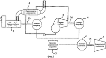
Фиг.1 представляет известное из уровня техники решение для привода в действие холодильного компрессора для сжижения природного газа, типовое для специализированных частотных преобразователей.Figure 1 represents a prior art solution for driving a refrigeration compressor for liquefying natural gas, typical of specialized frequency converters.
Фиг.2 представляет цепь привода компрессора для сжижения природного газа согласно существу изобретения для осуществления способов в соответствии с настоящим изобретением.Figure 2 represents the drive circuit of a compressor for liquefying natural gas according to the invention for implementing the methods in accordance with the present invention.
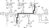
Фиг.3 представляет более подробно схему первого примера осуществления цепи привода в действие компрессора для сжижения природного газа в соответствии с настоящим изобретением.FIG. 3 is a more detailed diagram of a first embodiment of a drive circuit of a compressor for liquefying natural gas in accordance with the present invention.
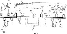
Фиг.4 представляет более подробно схему второго примера осуществления цепи привода в действие компрессора для сжижения природного газа в соответствии с настоящим изобретением.4 is a more detailed diagram of a second embodiment of a drive circuit of a compressor for liquefying natural gas in accordance with the present invention.
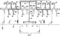
Фиг.5 представляет более подробную схему для совместно используемых силовых систем, которые могут работать на различных частотах.5 is a more detailed diagram for shared power systems that can operate at different frequencies.
Фиг.1 приводится для описания обычного уровня техники в качестве введения к описанию изобретения. На фиг.1 показан общий цикл выработки энергии (выработки пара и электроэнергии на парогенераторной установке), в котором электропривод с переменной скоростью вращения регулирует скорость электродвигателя. Холодильный компрессор 1 приводится в действие электродвигателем 2, который механически связан с приводным валом 10 компрессора 1. Чтобы регулировать скорость электродвигателя 2, известна методика введения привода с регулируемой скоростью (называемого также приводом с частотным регулированием) 3 между электрогенератором 4, 5 и электродвигателем 2. Привод с частотным регулированием действует путем преобразования входного сигнала переменного тока в постоянный ток и последующего генерирования переменного тока с иной частотой. Частота выходного электрического сигнала в приводе с частотным регулированием управляет скоростью электродвигателя, и привод с частотным регулированием обеспечивает частотное управление и, таким образом, регулирование частоты вращения. Благодаря приводу с регулируемой скоростью / с частотным регулированием турбина 7 и генератор 5 могут работать при относительно постоянной скорости, тогда как электродвигатель 2 и компрессор 1 могут менять скорость по мере необходимости. Эти принципы часто используются для широкого диапазона компрессорных приводов.Figure 1 is provided to describe the ordinary state of the art as an introduction to the description of the invention. Figure 1 shows the general cycle of energy production (generation of steam and electricity in a steam generator), in which the variable speed drive controls the speed of the electric motor. The
Для сжижения природного газа как части завода по переработке газа требуется несколько десятков мегаватт электроэнергии для привода в действие компрессора достаточной мощности, поэтому компоненты, например приводы с частотным регулированием, являются обычно крупными агрегатами, имеющими значительные затраты на их проектирование, монтаж и обслуживание.Liquefying natural gas as part of a gas processing plant requires several tens of megawatts of electricity to drive a compressor of sufficient power, therefore components, such as frequency-controlled drives, are usually large units that have significant costs for their design, installation and maintenance.
На фиг.2 показано, как такой привод компрессора для сжижения природного газа согласно настоящему изобретению может иметь упрощенный вид, предусматривающий запуск компрессоров определенным способом, и при этом компрессор при нормальной работе установлен для его привода в действие со скоростью, которая синхронизирована со скоростью турбины. Соответствующие способы для работы представленной на фиг.2 системы будут пояснены далее, при этом отдельные детали будут объяснены в отношении процедур запуска компрессора.Figure 2 shows how such a drive of a compressor for liquefying natural gas according to the present invention can have a simplified view, providing for the start of the compressors in a certain way, and the compressor during normal operation is set to drive it at a speed that is synchronized with the speed of the turbine. Appropriate methods for operating the system of FIG. 2 will be explained below, with individual details being explained with respect to compressor startup procedures.
На фиг.2 показано, как холодильный компрессор 1 приводится в действие электродвигателем 2. На электродвигатель 2 подается электрическое питание через сеть 40 передачи электрической энергии с помощью электрогенератора 4 и/или электрогенератора 5. Питание передается напрямую, без использования привода с регулируемой скоростью или привода с частотным регулированием. Электрогенераторы 4, 5 могут приводиться в действие паровой турбиной 6 и газовой турбиной 7, соответственно.Figure 2 shows how the
На фиг.3 показан более подробно пример осуществления изобретения, как существо изобретения, показанного на фиг.2, может быть реализовано в более сложной системе. Как и на фиг.2, холодильный компрессор 1А, 1В приводится в действие электродвигателем 2А, 2В, при этом электродвигатель механически связан с приводным валом 10А, 10В компрессора. Электродвигатель может быть подключен, например, через обычное коммутационное устройство или через распределительный щит, состоящее из двух секционных выключателей и выключателя питания (типовой для компоновок распределительных устройств с газовой изоляцией) 50А, 50В, к сети 40 передачи электрической энергии, которая в данном примере состоит из двух электрических шин 40а, 40b. Питание электродвигателя 2А, 2В в представленном на фиг.3 примере осуществляется от электрогенератора 4, который приводится в действие от паровой турбины 6. Электрогенератор 4 подключен к сети 40 передачи электрической энергии через второе коммутационное устройство 50В, которое может быть таким же, что и коммутационное устройство 50А.Figure 3 shows in more detail an example embodiment of the invention, as the essence of the invention shown in figure 2, can be implemented in a more complex system. As in FIG. 2, the
Предпочтительно сеть 40 передачи электрической энергии содержит сеть с двойной системой электрических шин, чтобы сделать возможным параллельное использование другого электрического оборудования вне зависимости от работы электрогенератора 4 для запуска электродвигателя 2А, 2В, который приводит в действие компрессор 1А, 1В. Это означает, что электрогенераторы 4, 5а, 5b могут быть подключены к электродвигателям 2а, 2b через любую из электрических шин 40а, 40b.Preferably, the electric
Сеть 40 может быть подключена к другой сети через межшинные соединения 60.
Помимо паровой турбины 6 и электрогенератора 4 система содержит также газовые турбины 7А, 7В и взаимосвязанные с ними электрогенераторы 5А, 5В. Они также могут использоваться для привода электродвигателей 2А, 2В или совместно с паровой турбиной 6 подавать питание на электродвигатели 2А, 2В.In addition to the
На фиг.4 показан второй подробный пример осуществления привода для сжижения природного газа согласно настоящему изобретению. Представленная на фиг.4 система в своей основе подобна системе на фиг.3. Однако она содержит блок 80 частотного преобразователя. Он может быть приспособлен для вращения привода компрессора на основе обычного частотного преобразователя. В этом случае блок 80 частотного преобразователя, который представляет собой интерфейс вставок постоянного тока, присоединяет первую силовую сеть 40В, к которой подключены механически связанные с газовыми турбинами 6А и 6В электрогенераторы 4А и 4В, ко второй силовой сети 40А, к которой подключены электродвигатель 2В и электрогенератор 5А. Электродвигатель 2В механически связан с компрессором 1В, а электрогенератор 5А механически связан с паровой турбиной 7А.4 shows a second detailed embodiment of a drive for liquefying natural gas according to the present invention. Presented in figure 4, the system is basically similar to the system in figure 3. However, it comprises a
Через частотный преобразователь 80 электроэнергия с переменной частотой может быть подана на электродвигатель 2В при его запуске, например, от газового компрессора 6А и электрогенератора 4А. После того как запуск пошел, электродвигатель 2В может работать при постоянной частоте тока, например в 60 Гц, подаваемого от электрогенератора 4а.Through a
После такой последовательности запуска синхронизированная обходная система, включая в себя межшинное соединение 60 или 70, может заменить блок 80 частотного преобразователя, то есть система частотного преобразователя отключается, тогда как межшинное соединение 60 или 70 объединяет первую и вторую силовые сети 40А, 40В. Поэтому становится возможным перевести электродвигатель 2В, как только он запущен, на местную сеть с фиксированной частотой и уровнями напряжения. Блок 80 частотного преобразователя теперь свободен и может быть использован для запуска другого электродвигателя.After this start-up sequence, a synchronized bypass system, including
В качестве примера, повторное использование мощного частотного преобразователя для синхронизации скорости вращения следует использовать в качестве одного конца в соединении линии постоянного тока высокого напряжения (HVDC-Light), например, производства компании ABB, или в соединении линии постоянного тока высокого напряжения (HVDC-Plus), например, производства компании Siemens AG, или подобной системной компоновки, обычно предназначенной для местных приводов или в качестве альтернативы линиям электропередачи для межсистемной связи, используемой для шунтирования региональных различий или подсоединения к некоторым другим отдаленным местностям, в которых существует рынок электроэнергии.As an example, the reuse of a powerful frequency converter to synchronize rotational speed should be used as one end in the connection of a high voltage direct current (HVDC-Light), for example, manufactured by ABB, or in the connection of a high voltage direct current (HVDC-Plus ), for example, manufactured by Siemens AG, or a similar system layout, usually designed for local drives or as an alternative to the interconnect power lines used for bridging regional differences or connected to some other remote areas, where there is market power.
Соединение линии постоянного тока высокого напряжения может быть включено, например, в принципы экономии/резервирования при выработке электроэнергии, если существуют возможности как для отправки, так и для ее получения в отдаленном месте, то есть становится возможным снижать затраты путем уменьшения количества приводов газовых турбин. Запуск электроснабжения может быть выполнен от местного или удаленного соединения в дополнение или вместо выработки указанными электрогенераторами.The connection of a high-voltage direct current line can be included, for example, in the principles of saving / redundancy when generating electricity, if there are opportunities for both sending and receiving it in a remote place, that is, it becomes possible to reduce costs by reducing the number of gas turbine drives. The start of the power supply can be performed from a local or remote connection in addition to or instead of being generated by said electric generators.
После того как описаны некоторые варианты осуществления привода компрессора для сжижения природного газа согласно настоящему изобретению, далее будут подробно рассмотрены некоторые способы запуска электродвигателя 2.After some embodiments of a compressor drive for liquefying natural gas according to the present invention have been described, some methods for starting an
Первый способ запускаFirst way to start
Запуск крупного или особо крупного компрессорного привода с помощью электрической схемы изменения частоты и напряжения, в частности, с использованием электрогенератора, приводимого в действие паровой турбиной (см. фиг.3).Starting a large or especially large compressor drive using an electric circuit for changing the frequency and voltage, in particular, using an electric generator driven by a steam turbine (see figure 3).
1. Приводимый в действие от паровой турбины электрогенератор 4 неподвижен (паровая турбина обычно должна быть прогрета перед подключением к ней какой-либо существенной нагрузки) и предназначен для запуска приводимого в действие конкретным электродвигателем 2А компрессора 1А. Предпочтительно электрогенератор и электродвигатель соединены в «автономном режиме», то есть эти два агрегата соединены так, чтобы на них не оказывали влияния другие системы, например, путем использования только одной электрической шины 40а, 40b из двойной системы электрических шин, как показано на фиг.3.1. The
2. Затем электрогенератор 4 и электродвигатель 2А электрически переводятся в режим бездействия, и их система возбуждения активируется подачей питания от другого источника.2. Then, the
3. Затем вся линия, включающая турбину 6, электрогенератор 4, электродвигатель 2А и компрессор 1А, одновременно запускается. Если валоповоротные устройства газовой турбины 6 работают в то время, когда электрогенератор 4 и электродвигатель 2А переходят в возбужденное состояние, тогда компрессор 1А будет пытаться следовать за ними.3. Then the entire line, including the
4. Теперь запущен поток пара, и приводимый в движение паровой турбиной электрогенератор 4 будет создавать электрическую мощность, подобную частотному преобразователю, и вся электрически взаимосвязанная кинематическая цепь 4, 2А, через сеть 40 передачи электрической энергии (как показано, через электрическую шину 40а) будет плавно запускаться и разгонять две синхронные машины 4, 2А.4. Now the steam flow is started, and the
5. Когда две синхронные машины 4, 2А, работающие как электрогенератор 4 и электродвигатель 2А, достигают заданной скорости, вся кинематическая цепь 2А, 4 может быть синхронизирована через сеть 40 передачи электрической энергии с остальной электрический сетью (через межшинные соединения 60, 65).5. When two
Описанный выше способ может также быть использован, чтобы создать возможность для псевдоодновременного пуска нескольких электрически взаимосвязанных синхронных машин, то есть как электродвигателей, так и электрогенераторов. Вероятно, этот способ хорошо подходит для производства сжиженного природного газа из удаленных и изолированных газовых месторождений, а также небольших месторождений нефти и/или газа, не имеющих доступа к трубопроводам. В этом способе запуска двухвальная или многовальная газовая турбина могла бы заменить паровую турбину.The method described above can also be used to create the possibility for pseudo-simultaneous start-up of several electrically interconnected synchronous machines, that is, both electric motors and electric generators. This method is probably well suited for the production of liquefied natural gas from remote and isolated gas fields, as well as small oil and / or gas fields that do not have access to pipelines. In this starting method, a twin-shaft or multi-shaft gas turbine could replace a steam turbine.
Второй способ запускаSecond way to start
Запуск крупного или особо крупного компрессорного привода с помощью электрической схемы изменяемой частоты и напряжения с использованием приводимого в действие паровой турбиной электрогенератора (см. фиг.3).Starting a large or especially large compressor drive using an electric circuit of variable frequency and voltage using an electric generator driven by a steam turbine (see figure 3).
1. В исходном положении приводимый в действие от газовой турбины 7А электрогенератор 5А замедляет скорость вращения до обычно 60% или до минимальной скорости, развозбуждается и предназначается для запуска приводимого в действие конкретным электродвигателем 2А компрессора 1А.1. In the initial position, the
2. Электрогенератор 5А и электродвигатель 2А затем электрически объединяются в невозбужденный режим, и затем активируется система возбуждения электрогенератора для плавного запуска невозбужденной синхронной машины в качестве асинхронного электродвигателя обычно при 60% рабочей частоты. Демпфирующая обмотка синхронной машины не должна быть перегружена в асинхронном режиме или при работе асинхронной машины, так как необходимый для разгона компрессора до приблизительно 60% скорости момент довольно ограничен.2. The
3. Когда «асинхронный двигатель» приближается к синхронной скорости, он возбуждается и входит в синхронный режим работы совместно с приданым электрогенератором.3. When the “asynchronous motor” approaches the synchronous speed, it is excited and enters the synchronous operation mode together with the dowry generator.
4. Когда работающие в качестве электрогенератора синхронные машины и электродвигатель достигают установленной скорости, тогда вся последовательность может быть синхронизирована с остальной системой электроснабжения.4. When the synchronous machines and the electric motor operating as an electric generator reach the set speed, then the whole sequence can be synchronized with the rest of the power supply system.
Этот второй способ запуска рассматривается как достаточно надежный способ запуска и рассматривается также для обеспечения одновременного запуска нескольких электрически соединенных между собой синхронных машин, даже если применяются блоки трансформаторов. Таким образом, этот способ обеспечивает гибкость в выборе дополнительного оборудования.This second start-up method is considered as a sufficiently reliable start-up method and is also considered to ensure the simultaneous start-up of several synchronous machines electrically interconnected, even if transformer blocks are used. Thus, this method provides flexibility in the selection of additional equipment.
Третий способ запускаThird way to run
Запуск с регулируемой частотой с использованием синхронизирующего шунтирования при номинальной скорости (см. фиг.4).Trigger with adjustable frequency using synchronizing bypass at rated speed (see figure 4).
1. Синхронизирующая обходная цепь 60, 70 для синхронизации скорости разомкнута, и между электродвигателем 2В и одним или более электрогенераторами 4А, 4В подключается блок 80 частотного преобразователя. Электрогенераторы 4А, 4В подают питание для разгона электродвигателя 2В из, по возможности, бездействующего состояния.1. A synchronizing
2. Когда компрессор 1В достигает номинальной скорости, блок 80 частотного преобразователя отключается, а синхронизирующая обходная цепь 60, 70 подключается к незагруженному частотному преобразователю и позволяет электродвигателю быть приводимым в действие от местной силовой цепи 40а, 40b. Когда этот процесс завершается, схема «переменный ток - постоянный ток - постоянный ток - переменный ток» или блок 80 частотного преобразователя высвобождаются для использования для запуска другого электродвигателя, например электродвигателя 2А, или для других целей.2. When the
Этот третий способ запуска может быть достаточно удобным для устройств, в которых возможно использовать блок частотного преобразователя для более чем одного назначения. Если это устройство является применимым для соединения с другой системой энергоснабжения через интерфейс вставок постоянного тока, следует обратить внимание на то, что при описанной компоновке будет возможно запускать привод компрессора с постоянной скоростью независимо от других удаленных концов вставок постоянного тока, см. фиг.4. С помощью этого способа запуска электрогенераторы и электродвигатели могут быть запущены обычным способом, но без необходимости в специальном частотном преобразователе для каждого электродвигателя. Следовательно, количество частотных преобразователей может быть уменьшено всего лишь до одного.This third starting method can be convenient enough for devices in which it is possible to use a frequency converter unit for more than one purpose. If this device is applicable for connecting to another power supply system through the interface of DC inserts, you should pay attention to the fact that with the described arrangement it will be possible to start the compressor drive at a constant speed regardless of the other remote ends of the DC inserts, see figure 4. Using this starting method, electric generators and electric motors can be started in the usual way, but without the need for a special frequency converter for each electric motor. Therefore, the number of frequency converters can be reduced to just one.
Три вышеописанных способа предназначены, прежде всего, для электроприводов компрессоров без газовой или паровой турбины в механической кинематической цепи для приведения их в действие. Однако операция синхронизации скорости пригодна не только для компрессора. Главный принцип может быть с одинаковым успехом применен для запуска любого другого оборудования. Если на приведенных фигурах и в описании заменить холодильный компрессор (компрессоры) 1 на другое оборудование, такое, например, как газовый компрессор, насос или газовая турбина, которому необходим мощный электродвигатель для запуска, то привод с нерегулируемой скоростью и связанный с ним способ запуска раскрыты выше. Следует обратить внимание на то, что синхронный электродвигатель в вышеописанных способах запуска может быть заменен асинхронным электродвигателем, если существующий диапазон мощностей является подходящим.The three methods described above are primarily intended for electric drives of compressors without a gas or steam turbine in a mechanical kinematic circuit to drive them. However, the speed synchronization operation is suitable not only for the compressor. The main principle can be applied with equal success to start any other equipment. If in the figures and in the description to replace the refrigeration compressor (s) 1 with other equipment, such as a gas compressor, pump or gas turbine, which requires a powerful electric motor to start, then the variable speed drive and the associated starting method are disclosed above. It should be noted that the synchronous motor in the starting methods described above can be replaced by an asynchronous motor if the existing power range is suitable.
В примере, привод одновальной промышленной газовой турбины, включающий в кинематической цепи соответствующую электрическую машину, может быть разогнан от нулевой скорости до ram-скорости для газовой турбины на тех же принципах, что описаны для приводимых выше концепций электрически нерегулируемой скорости.In an example, a single-shaft industrial gas turbine drive including a corresponding electric machine in the kinematic circuit can be accelerated from zero speed to ram speed for a gas turbine on the same principles as described for the above concepts of electrically unregulated speed.
Со ссылкой на фиг.5 будет описана система, которая является подобной, однако несколько более сложной, чем представленная на фиг.4 система.With reference to FIG. 5, a system that is similar, but somewhat more complex than the system shown in FIG. 4, will be described.
В этом устройстве имеются четыре электрические шины 40а, 40b, 40 с, 40d, к которым может быть подключено множество электрогенераторов 4а-е, 5а-b и электродвигателей 2a-f. Каждый из электрогенераторов и электродвигателей может быть подключен к по меньшей мере двум из электрических шин 40a-d, a четыре электрических шины 40a-d могут быть подключены к любой другой электрической шине 40a-d через межшинные соединения 60а-b и 70а-b. Электрические шины могут быть также подключены к местной сети 90 энергоснабжения для подачи электроэнергии другим потребителям, помимо электродвигателей 2a-f, или для использования излишков электроэнергии, произведенной в местной сети 90 энергоснабжения. Для обмена электрической энергией переменного тока электрические шины 40a-d могут также быть подключены к сети 100 внешнего энергоснабжения, которая может быть национальной или региональной энергетической системой.This device has four
Если электрические шины 40a-d не взаимосвязаны между собой, они могут действовать на различных частотах, например, как показано, электрические шины 40а и 40с могут работать при частоте 56 Гц, а электрические шины 40b и 40d - при частоте 61 Гц. В случае работы электрических шин с одинаковой частотой, они могут быть соединены между собой. Такая приспособляемость создает возможность для адаптации компрессоров к различной производительности. Поэтому поставка, например, сжиженного природного газа может быть адаптирована к внешним потребностям без необходимости изменения скорости компрессоров.If the
Если передача электроэнергии осуществляется между любой из электрических шин 40a-d и местной сетью 90, осуществление этого становится возможным через вставку 91 постоянного тока, так что частота электрической шины 40a-d и местной электрической сети могут быть различны.If electric power is transferred between any of the
Кроме того, существует возможность подачи электроэнергии на частотный преобразователь 80 для запуска комбинации электрогенератора и электродвигателя от местной сети 90, как показано, с помощью звена 92.In addition, there is the possibility of supplying electricity to the
Возможна также система с количеством электрических шин более четырех.A system with more than four busbars is also possible.
Во всех приведенных выше примерах приводящий агрегат (турбина) и приводимый агрегат (компрессор) могут быть заменены агрегатами других типов, например дизельным двигателем в качестве приводящего агрегата и насосом в качестве приводимого агрегата, без отступления от сущности настоящего изобретения.In all the above examples, the drive unit (turbine) and the driven unit (compressor) can be replaced by other types of units, for example, a diesel engine as a driving unit and a pump as a driven unit, without departing from the essence of the present invention.
Не повторяя подробное описание для всех возможных применений, приведенное выше описание должно быть достаточным для любого специалиста, чтобы использовать сходную технику привода с нерегулируемой скоростью и соответствующий способ для любого другого применения, помимо предложенных компрессора или газовой турбины, при условии отсутствия внутренних особенностей этого применения, которые препятствовали бы такой компоновке системы. Вышеописанные компоновка системы и способ могут с тем же успехом быть использованы в приводах вращающегося оборудования всех типов, которое может монтироваться на валу, и обычно являются приводимыми в действие приводами, такими как, например, электрические машины и газовые турбины.Without repeating the detailed description for all possible applications, the above description should be sufficient for any specialist to use a similar variable speed drive technique and an appropriate method for any other application besides the proposed compressor or gas turbine, provided that there are no internal features of this application, that would prevent such a system layout. The system arrangement and method described above can equally well be used in drives of all types of rotating equipment that can be mounted on a shaft, and are typically driven drives, such as, for example, electric machines and gas turbines.
В том случае если турбины или генераторы, соответственно, вырабатывают больше энергии, чем это необходимо для первой электрической машины (машин), можно использовать частотный преобразователь 80 для выработки постоянного тока, пригодного для передачи в другие системы или сети. Также, частотный преобразователь 80 можно использовать для выработки электроэнергии, адаптированной к внешней электрической сети переменного тока, такой как внешняя сеть 100.In the event that the turbines or generators, respectively, generate more energy than is necessary for the first electric machine (s), you can use the
В целом было описано, как приводы компрессора применимы для электрически приводимой в действие работы с нерегулируемой скоростью, со ссылкой на завод по сжижению природного газа в качестве типичного примера. Благодаря устранению специального привода с регулируемой скоростью из электрического привода сжижающего газ компрессора или специальной паровой и/или газовой турбины из механического привода компрессора ожидается получение существенных преимуществ в стоимости, весе, пространстве.In general, it has been described how compressor drives are applicable for electrically driven, variable speed operation, with reference to a natural gas liquefaction plant as a typical example. By eliminating a special variable-speed drive from an electric drive of a gas-compressing compressor or a special steam and / or gas turbine from a mechanical drive of a compressor, significant advantages are expected in cost, weight, and space.
Подобная цепочка аргументации могла бы наиболее полно использоваться для привода магистрального подпорного компрессора и других крупных приводов, подходящих для работы с нерегулируемой скоростью, с целью улучшения бесперебойности и сокращения затрат на техническое обслуживание, строительство и т.д.Such a chain of argument could be most fully used to drive the main booster compressor and other large drives suitable for operation with unregulated speed, in order to improve uninterrupted operation and reduce the cost of maintenance, construction, etc.
Три описанные принципа синхронизации скорости соответствуют определенному переходному режиму и режиму бездействия завода по сжижению природного газа, включая запуск, и, кроме того, принципы нерегулируемой скорости являются более надежными по сравнению с неустановившимися изменениями или падениями напряжения, чем сопоставимые регулируемые приводы с частотным преобразователем.The three described principles of speed synchronization correspond to a specific transitional regime and the inactivity mode of a natural gas liquefaction plant, including start-up, and, in addition, the principles of uncontrolled speed are more reliable than unsteady changes or voltage drops than comparable adjustable frequency drive drives.
Следует также обратить особое внимание на то, что конструкция электрической системы, которая допускает запуск и работу крупных и/или удаленных приводов с нерегулируемой скоростью, основанная на представленных для настоящего изобретения принципах, предполагает приспособляемость, которая может дать возможность работы электрических приводов с нерегулируемой скоростью в сети электроснабжения с переменной сетевой частотой независимо от распределения электроэнергии с фиксированной частотой к нуждающимся потребителям и возможных соединений с местной, региональной или национальной энергосистемой.Particular attention should also be paid to the fact that the design of the electrical system, which allows the start and operation of large and / or remote drives with unregulated speed, based on the principles presented for the present invention, implies adaptability, which can enable the operation of electric drives with unregulated speed in power supply networks with a variable network frequency regardless of the distribution of electricity with a fixed frequency to needy consumers and possible connections eny with local, regional or national power grid.
Claims (38)
1) электрическое подключение первой электрической машины ко второй электрической машине осуществляется во время остановки или когда первая и/или вторая машина имеют низкую скорость, посредством чего соединение второй электрической машины является выделенным для первой электрической машины;
2) в фазе ускорения разгон первой электрической машины осуществляется разгоном второй электрической машины с механическим приводом;
3) когда первая электрическая машина достигла заранее определенной скорости вращения, осуществляется ее синхронизация с местной сетью энергоснабжения и подключение ее к этой сети.1. A method for starting and operating an electrically driven load, for example, a compressor (1) or a pump, by supplying energy from a mechanical drive, for example, a turbine or internal combustion engine, whereby the load is mechanically connected to the first electric machine, and the mechanical drive is mechanically connected to the second electric machine, characterized in that
1) the electrical connection of the first electric machine to the second electric machine occurs during a stop or when the first and / or second machine have a low speed, whereby the connection of the second electric machine is dedicated to the first electric machine;
2) in the acceleration phase, the acceleration of the first electric machine is carried out by the acceleration of the second electric machine with a mechanical drive;
3) when the first electric machine has reached a predetermined rotation speed, it is synchronized with the local power supply network and connected to this network.
1) в фазе ускорения разгон первой электрической машины, такой как электродвигатель, для названной нагрузки осуществляется от нулевой, близкой к нулевой или малой скорости посредством либо
a) разгона второй электрической машины, соединенной с механическим приводом, при этом вторая электрическая машина электрически подключена к первой электрической машине и функционирует в качестве электрогенератора, посредством чего соединение второй электрической машины является выделенным для первой электрической машины, либо
b) подачи электроэнергии к первой электрической машине от частотного преобразователя,
2) осуществляется синхронизация первой электрической машины с местной сетью энергоснабжения, после чего
3) после завершения фазы ускорения работа первой электрической машины осуществляется путем подачи к ней электроэнергии от местной сети энергоснабжения, при этом сеть снабжается энергией от
a) внешней сети энергоснабжения, или
b) по меньшей мере одного механического привода, соединенного по меньшей мере с одной второй электрической машиной, высвобождая тем самым частотный преобразователь для других задач.10. A method for starting and operating an electrically driven load, for example, a compressor (1) or a pump, which is driven by the first electric machine by supplying energy from a mechanical drive, such as a turbine or internal combustion engine, or from a frequency converter that receives energy from an external power supply network, or from a local source, such as a mechanical drive, characterized in that
1) in the acceleration phase, the acceleration of the first electric machine, such as an electric motor, for the named load is carried out from zero, close to zero or low speed by means of either
a) accelerating a second electric machine connected to a mechanical drive, wherein the second electric machine is electrically connected to the first electric machine and functions as an electric generator, whereby the connection of the second electric machine is dedicated to the first electric machine, or
b) supplying electricity to the first electric machine from a frequency converter,
2) the first electric machine is synchronized with the local power supply network, after which
3) after the completion of the acceleration phase, the operation of the first electric machine is carried out by supplying electricity to it from the local power supply network, while the network is supplied with energy
a) an external power supply network, or
b) at least one mechanical drive connected to at least one second electric machine, thereby freeing up the frequency converter for other tasks.
подача электроэнергии к первой электрической машине обеспечена механическим приводом, который механически подключен ко второй электрической машине, функционирующей в качестве генератора, при этом вторая электрическая машина предназначена быть однозначно подключенной к первой электрической машине или к нескольким первым электрическим машинам, посредством чего система приспособлена разгонять первую электрическую машину (машины) путем регулируемой подачи энергии от второй электрической машины к первой электрической машине.18. The starting and operating system for starting and operating at least one mechanical load, wherein the load is connected to and driven from the at least one first electric machine, characterized in that
the electric power is supplied to the first electric machine by a mechanical drive that is mechanically connected to a second electric machine functioning as a generator, while the second electric machine is designed to be uniquely connected to the first electric machine or to several first electric machines, whereby the system is adapted to accelerate the first electric machine (s) by controlled supply of energy from the second electric machine to the first electric machine.
- механический привод, подключенный ко второй электрической машине, при этом вторая электрическая машина приспособлена быть однозначно электрически подключенной к одной или нескольким первым электрическим машинам, работая тем самым в качестве генератора в течение фазы ускорения или последующей рабочей фазы,
- частотный преобразователь, такой как привод с частотным регулированием, приспособленный быть однозначно подключенным к одной или нескольким первым электрическим машинам, разгоняя тем самым первую электрическую машину в фазе ускорения или обеспечивая работу первой электрической машины в рабочей фазе, посредством чего
частотный преобразователь приспособлен для снабжения его электроэнергией либо от внешней сети энергоснабжения, либо от местной сети энергоснабжения.28. The starting and operating system for starting and operating at least one mechanical load, such as a compressor or pump, wherein the load is connected to and driven from at least one first electric machine, characterized in that the system comprises
- a mechanical drive connected to the second electric machine, while the second electric machine is adapted to be uniquely electrically connected to one or more of the first electric machines, thereby operating as a generator during the acceleration phase or subsequent working phase,
- a frequency converter, such as a frequency-controlled drive, adapted to be uniquely connected to one or more first electric machines, thereby accelerating the first electric machine in the acceleration phase or ensuring the operation of the first electric machine in the working phase, whereby
the frequency converter is adapted to supply electric power either from an external power supply network or from a local power supply network.
Applications Claiming Priority (2)
| Application Number | Priority Date | Filing Date | Title |
|---|---|---|---|
| NO20064084 | 2006-09-12 | ||
| NO20064084A NO326634B1 (en) | 2006-09-12 | 2006-09-12 | Method and system for starting and operating an electrically driven load |
Publications (2)
| Publication Number | Publication Date |
|---|---|
| RU2009113662A RU2009113662A (en) | 2010-10-20 |
| RU2435966C2 true RU2435966C2 (en) | 2011-12-10 |
Family
ID=39184223
Family Applications (1)
| Application Number | Title | Priority Date | Filing Date |
|---|---|---|---|
| RU2009113662A RU2435966C2 (en) | 2006-09-12 | 2007-09-12 | Method and system of start and operation of electrically driven load |
Country Status (9)
| Country | Link |
|---|---|
| US (2) | US8269449B2 (en) |
| EP (1) | EP2070185B1 (en) |
| JP (1) | JP5656404B2 (en) |
| AU (1) | AU2007295187B2 (en) |
| BR (1) | BRPI0716780B1 (en) |
| CA (1) | CA2663268C (en) |
| NO (1) | NO326634B1 (en) |
| RU (1) | RU2435966C2 (en) |
| WO (1) | WO2008033033A2 (en) |
Families Citing this family (32)
| Publication number | Priority date | Publication date | Assignee | Title |
|---|---|---|---|---|
| EP2101039A1 (en) * | 2008-03-11 | 2009-09-16 | Siemens Aktiengesellschaft | Continuous operation and power supply of an acid gas reinjection facility |
| DE102008039449A1 (en) * | 2008-08-25 | 2010-03-04 | Rheinisch-Westfälische Technische Hochschule Aachen | Emission-free Karftwerk |
| EP2226928A1 (en) * | 2009-03-03 | 2010-09-08 | Bluewater Energy Services B.V. | Semi-direct variable speed drive with N+1 power availability |
| CN102498358B (en) | 2009-09-17 | 2015-01-14 | 国际壳牌研究有限公司 | Off-shore structure comprising two power systems and method of powering the same |
| US20110146293A1 (en) * | 2009-12-23 | 2011-06-23 | General Electric Company | Method for connecting a starting means to a turbomachine |
| CN102782429B (en) | 2010-03-05 | 2015-11-25 | 埃克森美孚上游研究公司 | Liquefied natural gas workshop equipment flexibly |
| WO2011159463A2 (en) * | 2010-06-17 | 2011-12-22 | Dresser-Rand Company | Variable speed high efficiency gas compressor system |
| AT510011B1 (en) * | 2010-09-06 | 2012-01-15 | Ge Jenbacher Gmbh & Co Ohg | POWER PLANT BLOCK |
| CN103119821B (en) | 2010-09-30 | 2016-01-13 | Abb研究有限公司 | Multiterminal HVDC system coordination controls |
| CN102022861B (en) * | 2010-12-01 | 2013-05-08 | 广东工业大学 | Hybrid type variable frequency air conditioning system with two working modes and control method thereof |
| EP2463978A1 (en) * | 2010-12-08 | 2012-06-13 | Alstom Technology Ltd | Power factor correction for multiple generators |
| US8855952B2 (en) * | 2011-01-05 | 2014-10-07 | Hamilton Sundstrand Corporation | Ram air turbine with flux regulated permanent magnet generator and testing method |
| DE102011081806A1 (en) * | 2011-08-30 | 2013-02-28 | Siemens Aktiengesellschaft | Safe motor starter |
| BRPI1103937A2 (en) * | 2011-09-05 | 2013-08-06 | Prates Joel Aires | automatic reversible synchronizer circuit |
| EP2644839B1 (en) * | 2012-03-26 | 2018-07-04 | General Electric Technology GmbH | Gas turbine start with frequency converter |
| US8742605B1 (en) * | 2013-02-07 | 2014-06-03 | Hamilton Sundstrand Corporation | Method for aircraft engine start using synchronous generator and constant speed drive |
| US20140260251A1 (en) * | 2013-03-13 | 2014-09-18 | Apache Corporation | Combined Heat and Power Technology for Natural Gas Liquefaction Plants |
| US9939194B2 (en) * | 2014-10-21 | 2018-04-10 | Kellogg Brown & Root Llc | Isolated power networks within an all-electric LNG plant and methods for operating same |
| JPWO2016129030A1 (en) * | 2015-02-09 | 2017-11-02 | 三菱重工コンプレッサ株式会社 | Gas turbine system |
| US9979339B2 (en) * | 2015-12-14 | 2018-05-22 | Rolls-Royce North American Technologies Inc. | Synchronous electric power distribution startup system |
| US10141874B2 (en) * | 2015-12-14 | 2018-11-27 | Rolls-Royce North American Technologies Inc. | Synchronous electrical power distribution system startup and control |
| WO2017106216A2 (en) * | 2015-12-14 | 2017-06-22 | Rolls-Royce North American Technologies Inc. | Synchronous electrical power distribution system startup and control |
| US10205415B2 (en) * | 2015-12-14 | 2019-02-12 | Rolls-Royce North American Technologies Inc. | Multiple generator synchronous electrical power distribution system |
| US10263553B2 (en) | 2015-12-14 | 2019-04-16 | Rolls-Royce North American Technologies Inc. | Synchronous electrical power distribution system |
| US10498275B2 (en) * | 2015-12-14 | 2019-12-03 | Rolls-Royce North American Technologies Inc. | Synchronous electrical power distribution excitation control system |
| WO2017163275A1 (en) * | 2016-03-23 | 2017-09-28 | 千代田化工建設株式会社 | Intake air cooling system and intake air cooling method for gas turbine |
| WO2017177612A1 (en) * | 2016-04-13 | 2017-10-19 | 冯伟忠 | Generalized frequency conversion system for steam turbine generator unit |
| CN105703676A (en) * | 2016-04-13 | 2016-06-22 | 冯伟忠 | Generalized frequency conversion system used for steam turbine generator unit |
| US11225910B2 (en) | 2019-11-05 | 2022-01-18 | General Electric Company | Load anticipator system for a generator system |
| US11028723B1 (en) * | 2019-11-21 | 2021-06-08 | Rolls-Royce Marine North America Inc. | Gas turbine generator load level control system |
| RU2737958C1 (en) * | 2020-06-27 | 2020-12-07 | Федеральное государственное бюджетное образовательное учреждение высшего образования «Магнитогорский государственный технический университет им. Г.И. Носова» | Device for starting powerful synchronous electric motors |
| CN114268249A (en) * | 2021-12-14 | 2022-04-01 | 大力电工襄阳股份有限公司 | High-voltage synchronous frequency conversion soft starting equipment and starting method thereof |
Family Cites Families (15)
| Publication number | Priority date | Publication date | Assignee | Title |
|---|---|---|---|---|
| JPS5858880A (en) * | 1981-10-02 | 1983-04-07 | Ebara Densan:Kk | Operating method for underwater pump for deep well |
| JPS6143752U (en) * | 1984-08-27 | 1986-03-22 | 工業技術院長 | Seal structure of underwater motor |
| US5152141A (en) * | 1991-04-08 | 1992-10-06 | Avco Corporation | Management of electrically driven engine accessories |
| JPH0767369A (en) | 1993-08-24 | 1995-03-10 | Fuji Electric Co Ltd | Synchronized starting of synchronous motor |
| FR2718902B1 (en) * | 1994-04-13 | 1996-05-24 | Europ Gas Turbines Sa | Turbine-generator assembly without reducer. |
| JP3563143B2 (en) | 1995-02-14 | 2004-09-08 | 千代田化工建設株式会社 | Compressor drive of natural gas liquefaction plant |
| NO960911A (en) | 1996-03-06 | 1997-05-05 | Linde Ag | Installations for the production of liquefied natural gas |
| IT1283373B1 (en) | 1996-07-31 | 1998-04-17 | Pirelli Cavi S P A Ora Pirelli | BIDIRECTIONAL MULTI-CHANNEL OPTICAL TELECOMMUNICATION SYSTEM |
| JP2001132648A (en) * | 1999-11-01 | 2001-05-18 | Hitachi Ltd | Starting method of private power generation for manhole pump |
| FI20020390A (en) * | 2002-02-28 | 2003-08-29 | Kylmaehertsi Oy | Method of controlling a cooling device |
| EG24658A (en) * | 2002-09-30 | 2010-04-07 | Bpcorporation North America In | All electric lng system and process |
| US6640586B1 (en) * | 2002-11-01 | 2003-11-04 | Conocophillips Company | Motor driven compressor system for natural gas liquefaction |
| AU2004289969B2 (en) * | 2003-11-06 | 2009-08-27 | Exxonmobil Upstream Research Company | Method for efficient, nonsynchronous LNG production |
| US7388303B2 (en) * | 2003-12-01 | 2008-06-17 | Conocophillips Company | Stand-alone electrical system for large motor loads |
| JP2011053043A (en) * | 2009-09-01 | 2011-03-17 | Ushio Inc | Clinical inspection apparatus |
-
2006
- 2006-09-12 NO NO20064084A patent/NO326634B1/en unknown
-
2007
- 2007-09-12 EP EP07834741.6A patent/EP2070185B1/en active Active
- 2007-09-12 AU AU2007295187A patent/AU2007295187B2/en not_active Ceased
- 2007-09-12 CA CA2663268A patent/CA2663268C/en active Active
- 2007-09-12 BR BRPI0716780-6A patent/BRPI0716780B1/en not_active IP Right Cessation
- 2007-09-12 RU RU2009113662A patent/RU2435966C2/en active
- 2007-09-12 JP JP2009528193A patent/JP5656404B2/en not_active Expired - Fee Related
- 2007-09-12 US US12/441,046 patent/US8269449B2/en active Active
- 2007-09-12 WO PCT/NO2007/000322 patent/WO2008033033A2/en active Application Filing
-
2012
- 2012-08-20 US US13/589,705 patent/US8872467B2/en active Active
Also Published As
| Publication number | Publication date |
|---|---|
| AU2007295187B2 (en) | 2011-09-22 |
| EP2070185A4 (en) | 2014-04-02 |
| BRPI0716780B1 (en) | 2023-05-16 |
| JP5656404B2 (en) | 2015-01-21 |
| CA2663268A1 (en) | 2008-03-20 |
| US8872467B2 (en) | 2014-10-28 |
| AU2007295187A1 (en) | 2008-03-20 |
| US20120313372A1 (en) | 2012-12-13 |
| EP2070185B1 (en) | 2018-11-07 |
| BRPI0716780A2 (en) | 2014-11-18 |
| CA2663268C (en) | 2017-01-10 |
| NO20064084L (en) | 2008-03-13 |
| WO2008033033A3 (en) | 2008-05-08 |
| US8269449B2 (en) | 2012-09-18 |
| JP2010503791A (en) | 2010-02-04 |
| US20100019717A1 (en) | 2010-01-28 |
| NO326634B1 (en) | 2009-01-26 |
| WO2008033033A2 (en) | 2008-03-20 |
| RU2009113662A (en) | 2010-10-20 |
| EP2070185A2 (en) | 2009-06-17 |
Similar Documents
| Publication | Publication Date | Title |
|---|---|---|
| RU2435966C2 (en) | Method and system of start and operation of electrically driven load | |
| JP2010503791A5 (en) | ||
| JP2018198525A (en) | Ac coupling type power electronics system for fuel cell power system | |
| JPH08265991A (en) | Power plant and controller therefor | |
| CN103732490A (en) | Improvement in ship propulsion engine fuel efficiency | |
| US10570827B2 (en) | Gas turbine train with starter motor | |
| CN101867341A (en) | System and method for fixed frequency power generation | |
| CN107112854B (en) | Device and method for driving a variable-speed working apparatus | |
| KR101276954B1 (en) | A method for supplying outside energy to an onboard electrical power network of a ship, a ship with such an outside energy supply | |
| WO2024001673A1 (en) | Thermal power energy storage black start system | |
| KR20210145162A (en) | How to self-start the electric grid | |
| JP2022505734A (en) | Hybrid synchronous capacitor and power generator | |
| CN101826829B (en) | For controlling the system and method for the speed of each in N number of varying speed motor | |
| JP2012500608A (en) | Power plant facilities for selective operation in power networks with different network frequencies | |
| RU2272938C1 (en) | Compressor station | |
| RU53081U1 (en) | POWER SUPPLY SYSTEM | |
| JP2008131694A (en) | Gas turbine power generator | |
| CN106887992A (en) | A kind of electric energy conversion of many buses and switching system | |
| CN207021922U (en) | A kind of electric energy conversion of more buses and switching system | |
| RU2272937C1 (en) | Method of operating compression station for main gas pipeline | |
| CN1051466A (en) | Uninterrupted power supply(ups) with gas turbine as power | |
| JP2013034286A (en) | Starting device and starting method for power generation system including main power generator and auxiliary machine | |
| KR20130071971A (en) | Frequency converter apparatus for ship | |
| KR20040014649A (en) | Motor Generation System |
Legal Events
| Date | Code | Title | Description |
|---|---|---|---|
| PC43 | Official registration of the transfer of the exclusive right without contract for inventions |
Effective date: 20190712 |
|
| PD4A | Correction of name of patent owner |