RU2435003C2 - Fastening system made of dowel and plastic nail and method to install insulation panels - Google Patents
Fastening system made of dowel and plastic nail and method to install insulation panels Download PDFInfo
- Publication number
- RU2435003C2 RU2435003C2 RU2009106581/03A RU2009106581A RU2435003C2 RU 2435003 C2 RU2435003 C2 RU 2435003C2 RU 2009106581/03 A RU2009106581/03 A RU 2009106581/03A RU 2009106581 A RU2009106581 A RU 2009106581A RU 2435003 C2 RU2435003 C2 RU 2435003C2
- Authority
- RU
- Russia
- Prior art keywords
- nail
- spacer
- head
- plug
- spacer nail
- Prior art date
Links
- 238000009413 insulation Methods 0.000 title claims abstract description 17
- 238000000034 method Methods 0.000 title claims abstract description 8
- 125000006850 spacer group Chemical group 0.000 claims abstract description 70
- 239000000463 material Substances 0.000 claims description 8
- 241000587161 Gomphocarpus Species 0.000 claims description 4
- 230000003116 impacting effect Effects 0.000 claims 2
- 238000000926 separation method Methods 0.000 claims 1
- 238000010276 construction Methods 0.000 abstract 1
- 238000003780 insertion Methods 0.000 abstract 1
- 230000037431 insertion Effects 0.000 abstract 1
- 239000000126 substance Substances 0.000 abstract 1
- 238000009434 installation Methods 0.000 description 8
- 239000011810 insulating material Substances 0.000 description 7
- 239000011248 coating agent Substances 0.000 description 3
- 238000000576 coating method Methods 0.000 description 3
- 239000012774 insulation material Substances 0.000 description 3
- XEEYBQQBJWHFJM-UHFFFAOYSA-N Iron Chemical compound [Fe] XEEYBQQBJWHFJM-UHFFFAOYSA-N 0.000 description 2
- 239000007799 cork Substances 0.000 description 2
- 239000012634 fragment Substances 0.000 description 2
- 230000035515 penetration Effects 0.000 description 2
- 230000035939 shock Effects 0.000 description 2
- 239000004575 stone Substances 0.000 description 2
- 229910000831 Steel Inorganic materials 0.000 description 1
- 238000007906 compression Methods 0.000 description 1
- 229910052742 iron Inorganic materials 0.000 description 1
- 230000013011 mating Effects 0.000 description 1
- 239000010959 steel Substances 0.000 description 1
Images


Classifications
-
- E—FIXED CONSTRUCTIONS
- E04—BUILDING
- E04D—ROOF COVERINGS; SKY-LIGHTS; GUTTERS; ROOF-WORKING TOOLS
- E04D3/00—Roof covering by making use of flat or curved slabs or stiff sheets
- E04D3/36—Connecting; Fastening
- E04D3/3601—Connecting; Fastening of roof covering supported by the roof structure with interposition of a insulating layer
- E04D3/3603—Connecting; Fastening of roof covering supported by the roof structure with interposition of a insulating layer the fastening means being screws or nails
-
- E—FIXED CONSTRUCTIONS
- E04—BUILDING
- E04B—GENERAL BUILDING CONSTRUCTIONS; WALLS, e.g. PARTITIONS; ROOFS; FLOORS; CEILINGS; INSULATION OR OTHER PROTECTION OF BUILDINGS
- E04B1/00—Constructions in general; Structures which are not restricted either to walls, e.g. partitions, or floors or ceilings or roofs
- E04B1/62—Insulation or other protection; Elements or use of specified material therefor
- E04B1/74—Heat, sound or noise insulation, absorption, or reflection; Other building methods affording favourable thermal or acoustical conditions, e.g. accumulating of heat within walls
- E04B1/76—Heat, sound or noise insulation, absorption, or reflection; Other building methods affording favourable thermal or acoustical conditions, e.g. accumulating of heat within walls specifically with respect to heat only
- E04B1/762—Exterior insulation of exterior walls
- E04B1/7629—Details of the mechanical connection of the insulation to the wall
- E04B1/7633—Dowels with enlarged insulation retaining head
Abstract
Description
Область техники, к которой относится изобретениеFIELD OF THE INVENTION
Настоящее изобретение относится к крепежной системе и способу монтажа изоляционных панелей на основании, причем крепежная система состоит из распорного элемента с головкой распорного элемента и стержнем распорного элемента, а также дюбеля с прижимной шайбой и примыкающей к ней втулкой дюбеля.The present invention relates to a fastening system and a method of mounting insulating panels on a base, the fastening system consisting of a spacer with a spacer head and a spacer rod, as well as a dowel with a pressure washer and a dowel bush adjacent to it.
Уровень техникиState of the art
Для того чтобы получить предпочтительно ровную установку дюбелей заподлицо, то есть слегка заглубленную установку, обычные дюбели, в том случае, когда они прилегают к изоляционной панели с помощью прижимной шайбы, заглубляют дальше в изоляционный материал посредством дополнительных ударов по головке распорного элемента. При использовании гвоздей из железа или стали это не создает проблем. Однако в том случае, когда для достижения лучшего изоляционного действия для монтажа изоляционных панелей используются гвозди из пластика, создается риск повреждения гвоздя при чрезмерной осевой нагрузке или при косых ударах. В этом отношении проблема состоит в том, что строитель не всегда может ударить по гвоздю с точной желаемой силой и под одним и тем же углом. Другими словами, сила и направление удара не поддаются предварительному контролю.In order to obtain a predominantly even installation of the dowels flush, that is, a slightly recessed installation, conventional dowels, when they are adjacent to the insulation panel with the pressure washer, are further buried in the insulation material by additional impacts on the head of the spacer element. When using nails made of iron or steel, this does not cause problems. However, in the case when nails made of plastic are used for the installation of insulating panels to achieve the best insulation effect, the risk of damage to the nail is created due to excessive axial load or oblique impacts. In this regard, the problem is that the builder cannot always hit the nail with the exact desired strength and at the same angle. In other words, the force and direction of impact are not subject to preliminary control.
Из патентного документа ЕР 1318250 A3 известен дюбель для монтажа изоляционных панелей, который может быть полностью заглублен в изоляционную панель. Это производится с помощью специальных режущих устройств, которые расположены на наружной кромке прижимной головки или шайбы и при внедрении дюбеля врезаются в изоляционный материал. Посредством усилия, передаваемого на распорный элемент от устройства заглубления, изоляционный материал сжимается одновременно с врезанием в него прижимной шайбы. В примере осуществления изобретения описан дюбель, прижимная шайба которого соединена с втулкой дюбеля посредством выступа на нижнем конце прижимной шайбы и на верхнем конце втулки дюбеля. Это соединение между втулкой дюбеля и прижимной шайбой освобождается винтом, который приводится во вращение с помощью приводного инструмента. При этом соединение между втулкой дюбеля и стержнем выполнено таким, что оно реагирует на относительно равномерные крутящие моменты. Применение этой технологии к ударному дюбелю представляется нецелесообразным, поскольку, с одной стороны, при забивании гвоздей ударные усилия менее равномерны, и, с другой стороны, для заглубленной установки требуется вращательное движение для врезания в изоляционный материал.From the patent document EP 1318250 A3 a wall plug is known for mounting insulating panels, which can be completely buried in the insulating panel. This is done using special cutting devices that are located on the outer edge of the clamping head or washer and, when the dowel is inserted, cut into the insulating material. Through the force transmitted to the spacer element from the deepening device, the insulating material is compressed at the same time as the clamping plate is inserted into it. In an embodiment of the invention, a dowel is described, the clamping washer of which is connected to the dowel bush by a protrusion on the lower end of the clamping washer and on the upper end of the dowel bush. This connection between the dowel sleeve and the pressure washer is released by a screw, which is driven by a power tool. In this case, the connection between the dowel sleeve and the shaft is made such that it responds to relatively uniform torques. The application of this technology to a shock dowel seems impractical, since, on the one hand, when hammering nails, the impact forces are less uniform, and, on the other hand, for a recessed installation, a rotational movement is required to cut into the insulating material.
Раскрытие изобретенияDisclosure of invention
Задача, на решение которой направлено настоящее изобретение, заключается в создании дюбеля, который приспособлен специально для монтажа с распорным гвоздем из пластика без риска повреждения распорного гвоздя.The problem to which the present invention is directed is to create a dowel that is specially adapted for installation with a spacer nail made of plastic without risk of damage to the spacer nail.
В соответствии с изобретением решение поставленной задачи достигается за счет крепежной системы для монтажа изоляционных панелей, состоящей из распорного гвоздя с головкой распорного гвоздя и стержнем распорного гвоздя, а также дюбеля с прижимной шайбой и примыкающей к ней втулкой дюбеля, причем распорный гвоздь изготовлен из пластмассового материала, а на нижнем по направлению ввода конце прижимной шайбы предусмотрены радиально выступающие перемычки, которые отделены друг от друга проемами и обеспечивают соединение с втулкой дюбеля, при этом указанные перемычки выполнены с возможностью разрыва при вводе распорного гвоздя.In accordance with the invention, the solution to this problem is achieved by means of a fastening system for installing insulation panels, consisting of a spacer nail with a spacer nail head and a spacer nail shaft, as well as a plug with a clamping washer and a plug plug adjacent to it, and the spacer nail is made of plastic material and on the lower end of the clamping washer, radially protruding jumpers are provided, which are separated from each other by openings and provide connection with the plug of the dowel , while these jumpers are made with the possibility of rupture when you enter a spacer nail.
Задача решается также за счет способа монтажа изоляционной панели на основании с помощью распорного гвоздя, изготовленного из пластмассового материала, имеющего головку распорного гвоздя и стержень распорного гвоздя, а также дюбеля, имеющего прижимную шайбу и примыкающую к ней втулку дюбеля, содержащего, по меньшей мере, следующие шаги: просверливают отверстие сквозь изоляционную панель в основание, вводят дюбель со вставленным распорным гвоздем в указанное отверстие, забивают распорный гвоздь в прижимную шайбу и втулку дюбеля, пока головка распорного гвоздя не войдет в выемку прижимной шайбы, а прижимная шайба не прижмется к изоляционной панели, производят дальнейшее забивание головки распорного гвоздя предпочтительно посредством удара по головке распорного гвоздя, при этом обеспечивают разрыв перемычек, предусмотренных между прижимной шайбой и втулкой дюбеля, и скольжение прижимной шайбы по втулке дюбеля, причем обеспечивают, в конечном монтажном положении, расположение прижимной шайбы и головки распорного гвоздя заподлицо с верхней поверхностью изоляционной панели.The problem is also solved by the method of mounting the insulating panel on the base using a spacer nail made of plastic material having a spacer nail head and a spacer nail, as well as a dowel having a pressure washer and a dowel bush adjacent to it containing at least the following steps: drill a hole through the insulation panel into the base, insert the dowel with the inserted nail in the specified hole, hammer the spacer nail into the pressure washer and the dowel sleeve catching the spacer nail does not enter the recess of the clamping washer, and the clamping washer does not press against the insulating panel, further hammer the head of the spacer nail, preferably by hitting the head of the spacer nail, while ensuring that the jumpers provided between the clamping washer and the dowel sleeve break, and the clamping slide washers along the plug of the dowel, moreover, in the final mounting position, provide the location of the clamping washer and the head of the spacer nail flush with the upper surface of the insulating Neli.
За счет выполнения разрывных перемычек в соответствии с изобретением в процессе монтажа могут эффективно демпфироваться слишком высокие осевые нагрузки, так что при различных ударах высокой интенсивности могут без проблем использоваться распорные элементы из пластика.Due to the rupture bridges in accordance with the invention, axial loads that are too high can be effectively damped during installation, so that plastic spacers can be used without problems with various high-impact shocks.
В предпочтительном примере осуществления изобретения к головке распорного гвоздя примыкает конический участок. Головка распорного гвоздя и конический участок входят в соответствующую выемку в прижимной шайбе. Это необходимо для того, чтобы в конечном монтажном положении головка распорного элемента также была расположена заподлицо с верхней поверхностью изоляционной панели. Кроме того, при этом достигается эффективная передача усилия от распорного гвоздя на дюбель.In a preferred embodiment, a conical portion is adjacent to the head of the spacer nail. The head of the spacer nail and the conical section are included in the corresponding recess in the pressure washer. This is necessary so that in the final mounting position the head of the spacer element is also located flush with the upper surface of the insulation panel. In addition, this achieves an effective transfer of force from the expansion nail to the dowel.
Предпочтительно прижимная шайба после разрыва перемычек может скользить в осевом направлении вдоль втулки дюбеля. Это необходимо, например, для монтажа заподлицо с верхней поверхностью.Preferably, the pressure washer after rupture of the bridges can axially slide along the dowel sleeve. This is necessary, for example, for mounting flush with the top surface.
В следующем предпочтительном примере осуществления перемычки и проемы имеют одинаковые окружные длины. За счет этого осевая нагрузка распределяется равномерно, и это приводит к предварительно определенному равномерному разрыву при превышении определенной силы. Однако имеется также возможность того, что перемычки имеют меньшие окружные длины, чем проемы, или того, что перемычки имеют большие окружные длины, чем проемы.In a further preferred embodiment, the webs and openings have the same circumferential lengths. Due to this, the axial load is distributed evenly, and this leads to a predetermined uniform rupture in excess of a certain force. However, there is also the possibility that the jumpers have shorter circumferential lengths than the openings, or that the jumpers have longer circumferential lengths than the openings.
В предпочтительном примере осуществления способа по изобретению прижимную шайбу, предпочтительно с помощью дальнейших ударов по головке распорного гвоздя, заглубляют в изоляционную панель настолько, что в конечном монтажном положении на заглубленную прижимную шайбу может быть наложено покрытие.In a preferred embodiment of the method according to the invention, the pressure washer, preferably by further striking the head of the spacer nail, is buried in the insulating panel so that a coating can be applied to the buried pressure washer in the final mounting position.
Краткий перечень чертежейBrief List of Drawings
Далее со ссылками на прилагаемые чертежи будет подробно описан монтаж крепежной системы по изобретению с помощью способа по изобретению. На чертежах:Next, with reference to the accompanying drawings, the installation of the fastening system according to the invention using the method according to the invention will be described in detail. In the drawings:
фиг.1 изображает крепежную систему в разрезе,figure 1 depicts a mounting system in section
фиг.2 изображает крепежную систему в разрезе по линии II-II на фиг.1,figure 2 depicts a mounting system in section along the line II-II in figure 1,
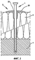
фиг.3 изображает в поперечном разрезе крепежную систему, введенную в изоляционную панель и основание,figure 3 depicts a cross-section of a fastening system inserted into the insulating panel and the base,
фиг.4 изображает в поперечном разрезе крепежную систему в процессе монтажа,figure 4 depicts a cross-section of a mounting system during installation,
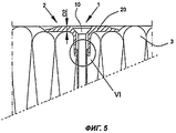
фиг.5 изображает в поперечном разрезе крепежную систему в конечном монтажном положении,5 is a cross-sectional view of a mounting system in a final mounting position,
фиг.6 изображает разомкнутое соединение между прижимной шайбой и втулкой дюбеля в конечном монтажном положении,6 depicts an open connection between the clamping washer and the plug of the dowel in the final mounting position,
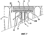
фиг.7 изображает в поперечном разрезе заделанную в изоляционный материал и покрытую крепежную систему,Fig.7 depicts in cross section embedded in an insulating material and coated mounting system,
фиг.8 изображает разомкнутое соединение между прижимной шайбой и втулкой дюбеля в заделанном и покрытом положении.Fig. 8 shows an open connection between a pressure washer and a dowel sleeve in a sealed and coated position.
Осуществление изобретенияThe implementation of the invention
На фиг.1 показана крепежная система, которая состоит из пластикового распорного гвоздя 1 и дюбеля 2. Распорный гвоздь 1 имеет головку 10 и примыкающий к ней конический участок 11. Конический участок 11 переходит в стержень 12 распорного гвоздя, который на чертеже показан не полностью. Распорный гвоздь 1 вставлен в дюбель 2 только частично, так что выемка 22 прижимной шайбы 20 еще не занята головкой 10 и коническим участком 11 гвоздя. Выемка 22 выполнена соответствующей или ответной головке 10 и коническому участку 11, так что обеспечивается возможность полной передачи усилия от распорного гвоздя 1 на дюбель 2. В конечном монтажном положении головка 10 не выступает над прижимной шайбой 20, то есть обеспечивается возможность их монтажа заподлицо (см. также фиг.4). К прижимной шайбе примыкает также втулка дюбеля. Между прижимной шайбой 20 и втулкой 21 дюбеля предусмотрено разрываемое соединение, видное на фиг.2.Figure 1 shows the mounting system, which consists of a
На фиг.2 показаны прижимная шайба 20, проемы или прорези 24 и перемычки 23, которые обеспечивают соединение с втулкой 21 дюбеля. Внутри втулки 21 дюбеля виден стержень 12 распорного гвоздя. Перемычки 23 и проемы 24, как правило, имеют одинаковую окружную длину. За счет этого осевая нагрузка равномерно распределяется на отдельные перемычки 23, что приводит к контролируемому разрыву перемычек 23 при превышении определенного усилия. Однако в зависимости от потребности их окружная длина может варьироваться. В том случае, когда перемычки 23 должны разрываться уже при относительно низкой нагрузке, они имеют окружную длину меньше окружной длины проемов 24. В противном случае, когда перемычки 23 должны разрываться только при относительно высокой нагрузке, они имеют окружную длину больше окружной длины проемов 24. В целом примерно половина окружного периметра втулки 21 дюбеля находится в соединении с перемычками 23. При этом обеспечивается нагрузка разрыва, специально рассчитанная для пластикового распорного гвоздя. Кроме того, показанный на чертеже размер или толщина D1 соответствует толщине перемычки 23 в сумме с толщиной стенки втулки 21 дюбеля, при этом указанные толщины, как правило, равны примерно половине толщины D1. Эти величины также могут варьироваться в зависимости от потребности.Figure 2 shows the
На фиг.3 показан дюбель 2, который введен через материал изоляционной панели 3 в основание в виде каменной стены 4 и прилегает прижимной шайбой 20 к изоляционной панели 3. Распорный гвоздь 1 уже вставлен в дюбель, однако он доходит в дюбеле 2 примерно до начала каменной стены 4, то есть при наличии в дюбеле распорной зоны она еще не активизирована.Figure 3 shows a
На фиг.4 распорный гвоздь 1 заглублен в прижимную шайбу 20 и втулку 21 дюбеля настолько, что головка 10 распорного элемента (и конический участок 11) входит в выемку 22 прижимной шайбы 20. Теперь головку 10 распорного гвоздя заглубляют дальше, что предпочтительно осуществляется путем удара по ней.In Fig. 4, the
Результат показан на фиг.5, где прижимная шайба 20 и головка 10 распорного гвоздя расположены заподлицо с верхней поверхностью изоляционной панели 3, при этом изоляционная панель 3 слегка сжата. На отдельном виде узла по фиг.6 видно, что перемычки 23, служащие в качестве соединения между втулкой 21 дюбеля и прижимной шайбой 20, разорваны вследствие осевой нагрузки, приложенной к головке распорного гвоздя. Как на втулке 21 дюбеля, так и на прижимной шайбе 20 остаются обрывки бывших перемычек 23, которые обычно разрываются примерно посредине. Наружная поверхность обрывков бывает, как правило, неровной. После этого прижимная шайба может скользить вдоль втулки 21 дюбеля для того, чтобы занять свое конечное монтажное положение, при этом обратный ход прижимной шайбы 20 соответствует примерно половине толщины D2 прижимной шайбы 20.The result is shown in FIG. 5, where the
На фиг.7 распорный гвоздь 1 и дюбель 2 показаны в положении заглубления в изоляционную панель 3. Такое заглубление дюбеля необходимо, когда желательно полное покрытие прижимной шайбы 20 изоляционным материалом. Для этого наносят дополнительные удары по головке распорного гвоздя, так что изоляционный материал под прижимной шайбой 20 дополнительно сжимается до тех пор, пока, например, втулка 21 дюбеля с обрывками бывших перемычек 23 не упрется в конический участок 11 распорного гвоздя 1 (см. вид узла по фиг.8). Как правило, предварительно с помощью соответствующего устройства в изоляционном материале вырезают круг примерно по диаметру прижимной шайбы, причем в изоляционном материале формируют гладкую торцевую поверхность. За счет этого обеспечивается сжатие изоляционного материала только под прижимной шайбой и предотвращается образование рваных кромок в изоляционной панели 3. По окончании процесса сжатия прижимная шайба 20 достигает внутри изоляционной панели 3 глубины, которая примерно соответствует толщине D3 предварительно изготовленной пробки или покрытия 5. Пробка или покрытие 5 изготовлены из того же материала, что и изоляционная панель 3 или, при необходимости, из другого подходящего материала. В установленном положении пробка или покрытие 5 расположены заподлицо с верхней поверхностью изоляционной панели 3.In Fig. 7, the
Claims (9)
a) просверливают отверстие сквозь изоляционную панель (3) в основание (4),
b) вводят дюбель (2) со вставленным распорным гвоздем (1) в указанное отверстие,
c) забивают распорный гвоздь (1) в прижимную шайбу (20) и втулку (21) дюбеля, пока головка (10) распорного гвоздя не войдет в выемку (22) прижимной шайбы (20), а прижимная шайба (20) не прижмется к изоляционной панели (3),
d) производят дальнейшее забивание головки (10) распорного гвоздя предпочтительно посредством удара по головке (10) распорного гвоздя, при этом
e) обеспечивают разрыв перемычек (23), предусмотренных между прижимной шайбой (20) и втулкой (21) дюбеля, и скольжение прижимной шайбы (20) по втулке (21) дюбеля, причем
f) обеспечивают в конечном монтажном положении расположение прижимной шайбы (20) и головки (10) распорного гвоздя заподлицо с поверхностью изоляционной панели (3).8. The method of mounting the insulating panel (3) on the base (4) using a spacer nail (1) made of plastic material having a spacer nail head (10) and a spacer nail shaft (12), and a wall plug (2) having a clamping washer (20) and a dowel sleeve (21) adjacent to it, comprising at least the following steps.
a) drill a hole through the insulating panel (3) into the base (4),
b) insert the dowel (2) with the inserted spacer nail (1) into the specified hole,
c) hammer the spacer nail (1) into the pressure washer (20) and the plug (21) of the expansion bolt shield until the head (10) of the expansion nail enters the recess (22) of the pressure washer (20) and the pressure washer (20) is not pressed against insulation panel (3),
d) further hammer the head (10) of the spacer nail, preferably by impacting the head (10) of the spacer nail, wherein
e) ensure the separation of the jumpers (23) provided between the clamping washer (20) and the plug (21) of the plug and the sliding of the clamping washer (20) along the plug (21) of the plug
f) ensure that the clamping washer (20) and the head (10) of the spacer nail are flush with the surface of the insulating panel (3) in the final mounting position.
a) просверливают отверстие сквозь изоляционную панель (3) в основание (4),
b) вводят дюбель (2) со вставленным распорным гвоздем (1) в указанное отверстие,
c) забивают распорный гвоздь (1) в прижимную шайбу (20) и втулку (21) дюбеля, пока головка (10) распорного гвоздя не войдет в выемку (22) прижимной шайбы (20), а прижимная шайба (20) не прижмется к изоляционной панели (3),
d) производят дальнейшее забивание головки (10) распорного гвоздя предпочтительно посредством удара по головке (10) распорного гвоздя, при этом
e) обеспечивают разрыв перемычек (23), предусмотренных между прижимной шайбой (20) и втулкой (21) дюбеля, и скольжение прижимной шайбы (20) по втулке (21) дюбеля, причем заглубляют прижимную шайбу (20) предпочтительно с помощью дальнейших ударов по головке (10) распорного гвоздя в изоляционную панель (3) настолько, что в конечном монтажном положении на заглубленную прижимную шайбу (20) может быть наложено покрытие (5). 9. The method of mounting the insulating panel (3) on the base (4) using a spacer nail (1) made of plastic material having a spacer nail head (10) and a spacer nail shaft (12), and a wall plug (2) having a pressure washer (20) and an adjacent plug (21) of the dowel, comprising at least the following steps:
a) drill a hole through the insulating panel (3) into the base (4),
b) insert the dowel (2) with the inserted spacer nail (1) into the specified hole,
c) hammer the spacer nail (1) into the pressure washer (20) and the plug (21) of the expansion bolt shield until the head (10) of the expansion nail enters the recess (22) of the pressure washer (20) and the pressure washer (20) is not pressed against insulation panel (3),
d) further hammer the head (10) of the spacer nail, preferably by impacting the head (10) of the spacer nail, wherein
e) break the jumpers (23) provided between the pressure washer (20) and the plug (21) of the plug and slide the pressure washer (20) along the plug (21) of the plug, and deepen the pressure washer (20) preferably by further striking the head (10) of the spacer nail in the insulation panel (3) so that in the final mounting position, a recessed clamping washer (20) can be coated (5).
Applications Claiming Priority (2)
| Application Number | Priority Date | Filing Date | Title |
|---|---|---|---|
| DE102006037025A DE102006037025A1 (en) | 2006-08-08 | 2006-08-08 | Fixing system made of dowel and plastic nail as well as method for mounting insulation boards |
| DE102006037025.2 | 2006-08-08 |
Publications (2)
| Publication Number | Publication Date |
|---|---|
| RU2009106581A RU2009106581A (en) | 2010-09-20 |
| RU2435003C2 true RU2435003C2 (en) | 2011-11-27 |
Family
ID=38608908
Family Applications (1)
| Application Number | Title | Priority Date | Filing Date |
|---|---|---|---|
| RU2009106581/03A RU2435003C2 (en) | 2006-08-08 | 2007-06-27 | Fastening system made of dowel and plastic nail and method to install insulation panels |
Country Status (9)
| Country | Link |
|---|---|
| EP (1) | EP2049745B1 (en) |
| CN (1) | CN101529029A (en) |
| AT (1) | ATE447648T1 (en) |
| DE (2) | DE102006037025A1 (en) |
| PL (1) | PL2049745T3 (en) |
| RU (1) | RU2435003C2 (en) |
| SI (1) | SI2049745T1 (en) |
| UA (1) | UA94616C2 (en) |
| WO (1) | WO2008017347A1 (en) |
Cited By (3)
| Publication number | Priority date | Publication date | Assignee | Title |
|---|---|---|---|---|
| RU2525395C2 (en) * | 2009-10-02 | 2014-08-10 | Климас Вкрэнт-Мэт Спулка З.О.О. | Dowel for insulation material |
| RU198438U1 (en) * | 2020-04-25 | 2020-07-09 | Александр Евгеньевич Куликов | Sheet dowel |
| RU207656U1 (en) * | 2021-06-02 | 2021-11-09 | Альберт Рафикович Гайнулин | UNIVERSAL INSULATION DOWEL |
Families Citing this family (10)
| Publication number | Priority date | Publication date | Assignee | Title |
|---|---|---|---|---|
| DE202008011892U1 (en) | 2008-09-05 | 2008-12-18 | Schlagmann Baustoffwerke Gmbh & Co. Kg | drilling |
| DE102008061430B4 (en) * | 2008-12-10 | 2012-04-26 | Ejot Baubefestigungen Gmbh | assembly tool |
| DE102010018515A1 (en) | 2009-04-29 | 2010-11-18 | Haacke Treuhand Gmbh | Wall element for thermal insulation of building facades, and for use in product line, and hence has outer layer facing outer chamber, where surface is designed to face towards building facade |
| AT510315B1 (en) * | 2010-08-27 | 2013-09-15 | Froewis Markus | ARRANGEMENT FOR, PARTICULARLY, DISTANCED, FASTENING AT LEAST ONE INSULATED PLATE TO A BUILDING |
| EP2610413B1 (en) | 2011-12-27 | 2015-06-17 | EJOT Baubefestigungen GmbH | Dowel with clamping sleeve |
| EP2796633B1 (en) | 2013-04-25 | 2016-11-02 | EJOT Baubefestigungen GmbH | Device and method for fixing an insulation panel with simultaneous heat insulation closure |
| DE102013111698B4 (en) | 2013-10-24 | 2022-06-09 | Klimas Sp. z o. o. | fastening system |
| US20150121792A1 (en) | 2013-11-06 | 2015-05-07 | Owens Corning Intellectual Capital, Llc | Composite thermal isolating masonry tie fastener |
| EP2915929B1 (en) * | 2014-03-07 | 2018-05-02 | RANIT-Befestigungssysteme GmbH | Method and fastening system for attaching, in particular mineral wool panels to a supporting base |
| HUE052473T2 (en) * | 2018-03-07 | 2021-05-28 | Ejot Baubefestigungen Gmbh | Method and system for fixing an insulating material |
Family Cites Families (4)
| Publication number | Priority date | Publication date | Assignee | Title |
|---|---|---|---|---|
| DE3128153A1 (en) * | 1981-07-16 | 1983-02-03 | Artur Dr.H.C. 7244 Waldachtal Fischer | Fastening element comprising a plastic nail and a plastic dowel |
| DE3907034A1 (en) * | 1989-03-04 | 1990-09-06 | Upat Max Langensiepen Kg | Expansion dowel |
| DE19808927C1 (en) * | 1998-03-03 | 1999-07-08 | Ejot Kunststofftech Gmbh | Insulation mounting connector for building wall |
| DK2752533T3 (en) * | 2001-12-05 | 2015-10-12 | Ejot Gmbh & Co Kg | An apparatus for driving a udspilingselement into a dowel |
-
2006
- 2006-08-08 DE DE102006037025A patent/DE102006037025A1/en not_active Ceased
-
2007
- 2007-06-27 SI SI200730151T patent/SI2049745T1/en unknown
- 2007-06-27 WO PCT/EP2007/005677 patent/WO2008017347A1/en active Application Filing
- 2007-06-27 CN CNA2007800296032A patent/CN101529029A/en active Pending
- 2007-06-27 EP EP07764880A patent/EP2049745B1/en active Active
- 2007-06-27 UA UAA200900856A patent/UA94616C2/en unknown
- 2007-06-27 RU RU2009106581/03A patent/RU2435003C2/en active
- 2007-06-27 PL PL07764880T patent/PL2049745T3/en unknown
- 2007-06-27 DE DE502007001928T patent/DE502007001928D1/en active Active
- 2007-06-27 AT AT07764880T patent/ATE447648T1/en active
Cited By (3)
| Publication number | Priority date | Publication date | Assignee | Title |
|---|---|---|---|---|
| RU2525395C2 (en) * | 2009-10-02 | 2014-08-10 | Климас Вкрэнт-Мэт Спулка З.О.О. | Dowel for insulation material |
| RU198438U1 (en) * | 2020-04-25 | 2020-07-09 | Александр Евгеньевич Куликов | Sheet dowel |
| RU207656U1 (en) * | 2021-06-02 | 2021-11-09 | Альберт Рафикович Гайнулин | UNIVERSAL INSULATION DOWEL |
Also Published As
| Publication number | Publication date |
|---|---|
| DE502007001928D1 (en) | 2009-12-17 |
| EP2049745B1 (en) | 2009-11-04 |
| ATE447648T1 (en) | 2009-11-15 |
| DE102006037025A1 (en) | 2008-02-14 |
| RU2009106581A (en) | 2010-09-20 |
| UA94616C2 (en) | 2011-05-25 |
| EP2049745A1 (en) | 2009-04-22 |
| SI2049745T1 (en) | 2010-03-31 |
| WO2008017347A1 (en) | 2008-02-14 |
| WO2008017347A8 (en) | 2009-03-12 |
| CN101529029A (en) | 2009-09-09 |
| PL2049745T3 (en) | 2010-04-30 |
Similar Documents
| Publication | Publication Date | Title |
|---|---|---|
| RU2435003C2 (en) | Fastening system made of dowel and plastic nail and method to install insulation panels | |
| EP1870533B1 (en) | Method for attaching insulating boards | |
| CA1041326A (en) | Self-drilling one-piece masonry anchor | |
| EP1738083B1 (en) | Method of fastening a guard rail by means of a guard rail bolt, the guard rail bolt and the tool for fastening the guard rail bolt | |
| KR102176905B1 (en) | Stucco wall reinforcement system and reinforcement method using the same | |
| CZ303125B6 (en) | Dowel pin with alternative anchorage of pressure plate in insulation, assembly method and mounting jig for making the same | |
| KR100900886B1 (en) | Apparatus fixing an insulating material to aluminium form | |
| JP5342118B2 (en) | Method of drilling bottomed hole in surface layer of concrete and anchor fitting used for drilling bottomed hole | |
| KR101265226B1 (en) | Using corn as a gap steel nail and its construction methods | |
| RU2180383C2 (en) | Holder for insulating material | |
| CA2671583A1 (en) | Flat ring-shaped anchoring element | |
| RU2525395C2 (en) | Dowel for insulation material | |
| JP2020033698A (en) | Hole-in anchor and construction method thereof | |
| JP2006016952A (en) | Anchor, method for temporarily fixing it, and temporary fixing structure using the same | |
| JP7054977B2 (en) | Mounting object mounting structure and its construction method | |
| JP3844487B1 (en) | Expanding anchor | |
| EP1867805A2 (en) | Method and device for installation of constructional elements, in particular insulation panels, onto a wall | |
| EP1591602B1 (en) | System for fastening components to a wall | |
| EP3833879B1 (en) | Method for temporarily releasing screw anchorage | |
| DE102020122156A1 (en) | Tool for setting an anchor nail | |
| KR200410781Y1 (en) | Ground reinforcement device | |
| KR20040089945A (en) | Drill aid apparatus for narrow portion and reparing and reinforcing method of structure by using the drill aid apparatus | |
| KR20190000078U (en) | Apparatus for strengthening the ground | |
| DE102016124992A1 (en) | Method, protective sleeve and kit for fixing an insulating panel | |
| JP3150420U (en) | Anchor bolt removal tool |