RU2434240C1 - Radio source and direction finder orientation determining method - Google Patents
Radio source and direction finder orientation determining method Download PDFInfo
- Publication number
- RU2434240C1 RU2434240C1 RU2010144727/09A RU2010144727A RU2434240C1 RU 2434240 C1 RU2434240 C1 RU 2434240C1 RU 2010144727/09 A RU2010144727/09 A RU 2010144727/09A RU 2010144727 A RU2010144727 A RU 2010144727A RU 2434240 C1 RU2434240 C1 RU 2434240C1
- Authority
- RU
- Russia
- Prior art keywords
- finding
- receiving devices
- antenna
- signals
- signal
- Prior art date
Links
Images
Abstract
Description
Изобретение относится к радиотехнике и может быть использовано в системах радиоконтроля и радиотехнической разведки для определения направления на источник радиоизлучения.The invention relates to radio engineering and can be used in systems of radio monitoring and radio intelligence to determine the direction of the source of radio emission.
Известны способы пеленгации радиосигналов и пеленгаторы для их осуществления, реализующие корреляционно-интерферометрический метод пеленгования (патент РФ №2190236 от 13.09.2000 г., патент РФ №2201599 от 27.03.2002 г., патент РФ №2263327 от 27.10.2005 г., патент РФ №2341811 от 20.12.2008 г.).Known methods for direction finding of radio signals and direction finders for their implementation, implementing the correlation-interferometric method of direction finding (RF patent No. 2190236 from 09/13/2000, RF patent No. 2201599 from 03/27/2002, RF patent No. 2263327 from 10/27/2005, RF patent No. 2341811 dated December 20, 2008).
Ограничением указанных способов и устройств является сравнительно узкая полоса частот одновременной разведки.A limitation of these methods and devices is the relatively narrow frequency band of simultaneous reconnaissance.
Известен способ обнаружения и определения пеленга и частоты ИРИ, реализующей корреляционную обработку на основе статического анализа спектральных плотностей энергии сигнала и шума (патент РФ №2190236 от 27.09.2002 г.). Ограничениями данного способа является достаточно большое время для проведения статического анализа.A known method of detecting and determining the bearing and frequency of the IRI, which implements correlation processing based on a static analysis of the spectral energy densities of the signal and noise (RF patent No. 2190236 from 09/27/2002). The limitations of this method is a sufficiently large time for conducting static analysis.
Известны также амплитудные и фазовые пеленгаторы (а.с. СССР №1840389, опубл. 20.11.06 г. и заявки JP 2005062144, опубл. 10.03.05 г., US 2006158375, опубл. 20.07.06 г., CN 101206257, опубл. 25.06.08 г., WO 2005073749, опубл. 11.08.2005 г.).Also known amplitude and phase direction finders (AS USSR No. 1840389, publ. 20.11.06, and applications JP 2005062144, publ. 10.03.05, US 2006158375, publ. 07.20.06, CN 101206257, publ. June 25, 2008, WO 2005073749, publ. August 11, 2005).
Ограничениями амплитудных пеленгаторов являются недостаточно высокая точность пеленгования из-за ошибок, вызванных неидентичностью коэффициентов усиления приемных каналов пеленгатора, особенно в широком диапазоне частот.The limitations of the amplitude direction finders are insufficiently high direction finding accuracy due to errors caused by the non-identity of the gain of the receiving channels of the direction finder, especially in a wide frequency range.
Ограничениями фазовых пеленгаторов является сравнительно узкая полоса частот одновременной разведки и ограниченная зона однозначного пеленгования, что вызывает необходимость применения многобазовых методов пеленгования.The limitations of phase direction finders are the relatively narrow frequency band of simultaneous reconnaissance and the limited zone of unambiguous direction finding, which necessitates the use of multi-base direction finding methods.
Наиболее близким к предлагаемому способу определения направления на источник радиоизлучения, входящим в группу изобретений, является способ амплитудного пеленгования источников радиоизлучений (патент РФ №2319975 от 20.03.2008 г.), в котором излучаемый сигнал принимают М идентичными антеннами, фокальные оси которых сдвинуты в плоскости пеленгования одна относительно другой таким образом, что диаграммы направленности смежных антенн пересекаются на уровне не более 3-х децибел, а все М антенн в сумме перекрывают сектор пеленгования 360°. Принятые сигналы распределяют по М идентичным приемным каналам, в каждом из которых поступивший в него сигнал усиливают, детектируют, результат детектирования усиливают в логарифмическом усилителе, измеряют мощность усиленных сигналов в канале с максимальным уровнем и в двух смежных с ним и по соотношению мощностей измеренных сигналов определяют направление на источник излучения, расчет направления φи на источник излучаемого сигнала осуществляют по формулам:Closest to the proposed method for determining the direction of the radio source, which is part of the group of inventions, is a method for amplitude direction finding of radio sources (RF patent No. 2319975 of 03.20.2008), in which the emitted signal is received by M identical antennas whose focal axes are shifted in the plane direction finding one relative to another so that the radiation patterns of adjacent antennas intersect at a level of no more than 3 decibels, and all M antennas in total overlap the direction finding sector 360 °. The received signals are distributed over M identical receiving channels, in each of which the signal received in it is amplified, detected, the detection result is amplified in a logarithmic amplifier, the power of the amplified signals in the channel with a maximum level is measured and in two adjacent signals and the ratio of the measured signal powers is determined direction to the radiation source, calculation of the direction φ and to the source of the emitted signal is carried out according to the formulas:
φи=φN+β·sign(PN+1-PN-1),φ and = φ N + β · sign (P N + 1 -P N-1 ),
где β - модуль углового отклонения направления на пеленгуемый источник излучения от фокальной оси антенны приемного канала с максимальным уровнем сигнала;where β is the module of the angular deviation of the direction to the direction-finding radiation source from the focal axis of the antenna of the receiving channel with the maximum signal level;
δ1, δ2, δ3 - модуль нормированного относительного (в децибелах) коэффициента усиления антенны при угловых отклонениях направления прихода сигнала от ее фокальной оси θ0, 4/3 θ0 и 2/3 θ0 соответственно;δ 1 , δ 2 , δ 3 - modulus of the normalized relative (in decibels) antenna gain with angular deviations of the signal arrival direction from its focal axis θ 0 , 4/3 θ 0 and 2/3 θ 0, respectively;
N - номер приемного канала с максимальным уровнем сигнала;N is the number of the receiving channel with the maximum signal level;
Pn, Pn+1, Pn-1 - относительные, отсчитанные от уровня чувствительности в децибелах уровни мощности принятого сигнала в N-м приемном канале и в смежных с ним справа и слева соответственно;P n , P n + 1 , P n-1 - relative, measured from the sensitivity level in decibels, power levels of the received signal in the N-th receiving channel and adjacent to it on the right and left, respectively;
φN - направление фокальной оси антенны N-го приемного канала.φ N is the direction of the focal axis of the antenna of the N-th receiving channel.
Данный способ выбран в качестве прототипа.This method is selected as a prototype.
Ограничениями указанного способа являются:The limitations of this method are:
- низкая чувствительность, так как для обнаружения сигнала одновременно в трех смежных каналах РПУ необходимо иметь запас по чувствительности пеленгатора не менее 15 дБ;- low sensitivity, since in order to detect a signal simultaneously in three adjacent channels of the RPU, it is necessary to have a margin in sensitivity of the direction finder of at least 15 dB;
- при работе в широком диапазоне частот и большом динамическом диапазоне входных сигналов возможно снижение точности пеленгования за счет неидентичности коэффициентов усиления различных каналов РПУ и изменения ширины ДН антенн, а следовательно, и соотношения уровней сигналов в соседних каналах;- when working in a wide range of frequencies and a large dynamic range of input signals, it is possible to reduce the accuracy of direction finding due to the non-identical amplification factors of the different channels of the RPU and the change in the width of the antenna paths, and therefore the ratio of signal levels in adjacent channels;
- достаточно высокая сложность реализации из-за большого числа приемных каналов.- a rather high complexity of implementation due to the large number of receiving channels.
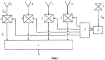
Наиболее близким к предлагаемому пеленгатору по принципу построения является пеленгатор по патенту DE 3347068 от 26.03.92 г., схема которого приведена на фиг.1. Пеленгатор содержит ненаправленную антенну 1, многоканальное радиоприемное устройство 2, делитель мощности 3, направленные пеленгационные антенны 4, смесители 5 и вычислительное устройство 6.Closest to the proposed direction finder according to the principle of construction is the direction finder according to the patent DE 3347068 from 03/26/92, a diagram of which is shown in figure 1. The direction finder comprises an
Принцип работы пеленгатора состоит в следующем. Всенаправленная антенна 1 и пеленгационные антенны 4 перекрывают весь рабочий диапазон частот. Многоканальное радиоприемное устройство 2 содержит m смежных частотных каналов, перекрывающих весь рабочий диапазон частот. При обнаружении источника радиоизлучения всенаправленной антенной 1 и j-м частотным каналом многоканального радиоприемного устройства 2 сигнал выделяется, усиливается и поступает через делитель мощности 3 на все смесители 5, которые настраиваются на частоту принятого сигнала. Вычислительное устройство 6 определяет направление на источник радиоизлучения известным моноимпульсным амплитудным методом по соотношению уровней сигналов в соседних пеленгационных каналах.The principle of operation of the direction finder is as follows. Omni-
Данный пеленгатор выбран в качестве прототипа заявленного пеленгатора.This direction finder is selected as a prototype of the claimed direction finder.
Ограничением данного пеленгатора является:The limitation of this direction finder is:
- низкое быстродействие, так как определение направления на каждый из обнаруженных всенаправленной антенной источников радиоизлучения осуществляется последовательно во времени;- low speed, since the determination of the direction of each of the detected omnidirectional antenna sources of radio emission is carried out sequentially in time;
- низкая чувствительность, так как чувствительность пеленгатора определяется каналом приема с всенаправленной антенной с низким коэффициентом усиления, а не направленной пеленгационной антенной, у которой коэффициент усиления существенно выше.- low sensitivity, since the sensitivity of the direction finder is determined by the reception channel with an omnidirectional antenna with a low gain, and not a directional direction finding antenna, in which the gain is much higher.
Основной задачей, на решение которой направлены заявляемый способ определения направления на источник радиоизлучения и пеленгатор, является улучшение основных технических характеристик.The main objective, the solution of which is claimed by the claimed method of determining the direction to the source of radio emission and direction finder, is to improve the basic technical characteristics.
Единым техническим результатом, достигаемым при осуществлении заявленной группы изобретений, является повышение чувствительности и точности пеленгования, а также быстродействия.A single technical result achieved in the implementation of the claimed group of inventions is to increase the sensitivity and accuracy of direction finding, as well as speed.
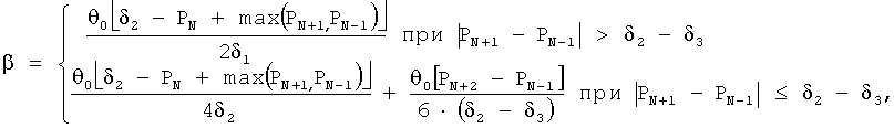
Указанный технический результат достигается тем, что в известном способе амплитудного пеленгования источников радиоизлучений, при котором излучаемый сигнал принимают пеленгационной антенной, состоящей из М идентичных антенн, фокальные оси которых сдвинуты друг относительно друга в плоскости пеленгования таким образом, что смежные диаграммы направленности антенн образуют идентичные пеленгационные характеристики, а в сумме М антенн перекрывают всю зону наблюдения 360°, согласно изобретению принятые сигналы распределяют по трем идентичным приемным устройствам, при этом обзор всей зоны наблюдения осуществляют электронным переключением М выходов пеленгационной антенны ко входам трех приемных устройств таким образом, что ко входам приемных устройств всегда на время определения направления на источник радиоизлучения подключены одновременно три смежные антенны, в каждом приемном устройстве принятые сигналы распределяют по идентичным частотным поддиапазонам, в каждом из которых сигналы усиливают, детектируют, результат детектирования усиливают логарифмическим видеоусилителем, измеряют мощность усиленных сигналов с учетом поправок на неидентичность коэффициентов передачи приемных устройств, которую определяют и запоминают при периодической калибровке приемных устройств в каждом поддиапазоне частот и в динамическом диапазоне входных сигналов, по соотношению мощностей определяют частотный поддиапазон, в котором принят сигнал, а для сигналов, имеющих максимальный уровень в приемном устройстве, подключенном к центральной из трех смежных антенн, определяют направление βi на i-й источник радиоизлучения по пеленгационным характеристикам, образованным центральной и одной из смежных антенн (правой или левой), с большей мощностью сигнала, для j-го частотного поддиапазона, в котором принят сигнал, по формулам:The specified technical result is achieved by the fact that in the known method of amplitude direction finding of radio emission sources, in which the emitted signal is received by a direction-finding antenna consisting of M identical antennas whose focal axes are shifted relative to each other in the direction-finding plane so that adjacent directional patterns of the antennas form identical direction-finding characteristics, and in total M antennas cover the entire 360 ° observation area, according to the invention, the received signals are distributed over three idents receiving antennas, while the entire observation area is surveyed by electronically switching the M outputs of the direction-finding antenna to the inputs of the three receiving devices in such a way that three adjacent antennas are always connected to the inputs of the receiving devices at the time of determining the direction to the radio emission source, received signals in each receiving device distributed over identical frequency subbands, in each of which the signals are amplified, detected, the detection result is amplified in a logarithmic form an amplifier, measure the power of the amplified signals, taking into account corrections for the non-identity of the transmission coefficients of the receiving devices, which is determined and stored during periodic calibration of the receiving devices in each frequency sub-range and in the dynamic range of the input signals, the frequency sub-range in which the signal is received is determined by the power ratio, and for signals having the maximum level at the receiver, connected to the central of three adjacent antennas define the direction β i to i-th source radioizlu eniya characteristics of DF formed by the central and one of the adjacent antennas (right or left), with a greater signal power for the j-th frequency subband, wherein the received signal by the formulas:
βi=βРСНk±Δβi,β i = β RSNk ± Δβ i ,
где βPCHk, градус - значение пеленга для равносигнального направления выбранной k-й пеленгационной характеристики.where β PCHk , degree is the bearing value for the equal-signal direction of the selected k-th direction-finding characteristic.
Значение +Δβ принимают при определении направления по пеленгационной характеристике, образованной центральной и левой смежными антеннами, а - Δβ - при определении направления по пеленгационной характеристике, образованной центральной и правой смежными антеннами.The value + Δβ is taken when determining the direction from the direction-finding characteristic formed by the central and left adjacent antennas, and - Δβ - when determining the direction from the direction-finding characteristic formed by the central and right adjacent antennas.
Δβi, градус=S(fj)·ΔPi,Δβ i , degree = S (f j ) · ΔP i ,
где Δβi - отклонение направления на i-й источник радиоизлучения от равносигнального направления выбранной k-й пеленгационной характеристики;where Δβ i is the deviation of the direction to the i-th source of radio emission from the equal-signal direction of the selected k-th direction finding characteristic;
S(fj), градус/дБ - крутизна пеленгационной характеристики в j-м частотном поддиапазоне:S (f j ), degree / dB is the steepness of the direction-finding characteristic in the j-th frequency subband:
ΔPi, дБ=Pц-Pл(п)±ΔPk(fj,Pi),ΔP i , dB = P c -P l (p) ± ΔP k (f j , P i ),
где Рц, Рл(п) - относительный уровень мощности сигнала в приемном устройстве, подключенном соответственно к центральной, левой (или правой) из трех смежных антенн;where R c , R l (p) is the relative signal power level in the receiving device, connected respectively to the central, left (or right) of the three adjacent antennas;
ΔPk(fj,Pi), дБ - неидентичность коэффициентов передачи приемных устройств, подключенных к центральной и левой (или правой) из трех смежных антенн в j-м частотном поддиапазоне при уровне мощности, соответствующей мощности входного сигнала.ΔP k (f j , P i ), dB is the non-identity of the transmission coefficients of the receiving devices connected to the central and left (or right) of the three adjacent antennas in the j-th frequency subband at a power level corresponding to the power of the input signal.
Значение ΔPk(fj,Pi) и знак плюс или минус определяют при калибровке приемных устройств по сигналам синтезатора рабочих частот.The value ΔP k (f j , P i ) and the plus or minus sign are determined when calibrating the receiving devices according to the signals of the operating frequency synthesizer.
Очевидно, что для определения направления достаточно двух смежных каналов пеленгационной антенны. В предложенном способе используют три смежных канала, так как левый и правый смежные каналы дополнительно используются для компенсации приема по ближним боковым лепесткам центральной антенны, уменьшая тем самым вероятность появления ложных пеленгов при большом уровне входных сигналов.Obviously, two adjacent channels of a direction-finding antenna are sufficient to determine the direction. In the proposed method, three adjacent channels are used, since the left and right adjacent channels are additionally used to compensate for the reception on the near side lobes of the central antenna, thereby reducing the likelihood of false bearings with a high level of input signals.
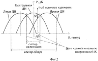
Структура диаграмм направленности пеленгационной антенны, поясняющая сущность способа определения направления на источник радиоизлучения, приведена на фиг.2.The structure of the direction-finding patterns of the direction-finding antenna, explaining the essence of the method for determining the direction to the source of radio emission, is shown in figure 2.
Указанный технический результат достигается также тем, что в пеленгаторе, содержащем многолучевую пеленгационную антенну, состоящую из М идентичных антенн, фокальные оси которых сдвинуты друг относительно друга в плоскости пеленгования таким образом, что диаграммы направленности смежных антенн образуют идентичные пеленгационные характеристики, а в сумме диаграммы направленности М антенн перекрывают всю зону наблюдения 360°, ненаправленную антенну компенсации приема по боковым лепесткам, четыре идентичных приемных устройства, каждое из которых представляет собой многоканальный приемник и устройство анализа и управления, согласно изобретению выходы многолучевой пеленгационной антенны через переключатель, имеющий М входов и три выхода и через направленный ответвитель подключены ко входам трех приемных устройств, причем переключатель при любых переключениях обеспечивает одновременное подключение выходов трех смежных антенн, ненаправленная антенна также через направленный ответвитель подключена к четвертому приемному устройству, а выходы всех четырех приемных устройств подключены ко входам устройства анализа и управления, управляющие выходы которого подключены ко всем приемным устройствам, переключателю и синтезатору рабочих частот, выход которого через направленный ответвитель подключен ко входам всех четырех приемных устройств.The specified technical result is also achieved by the fact that in the direction finder containing a multi-beam direction-finding antenna, consisting of M identical antennas, the focal axes of which are shifted relative to each other in the direction-finding plane so that the radiation patterns of adjacent antennas form identical direction-finding characteristics, and in the sum of the radiation patterns M antennas cover the entire 360 ° viewing area, an omnidirectional receive compensation antenna along the side lobes, four identical receiving devices, each of which is a multi-channel receiver and analysis and control device, according to the invention, the outputs of a multi-beam direction-finding antenna through a switch having M inputs and three outputs and through a directional coupler are connected to the inputs of three receiving devices, and the switch, at any switching, provides simultaneous connection of the outputs of three adjacent antennas , the omnidirectional antenna is also connected through the directional coupler to the fourth receiving device, and the outputs of all four receiving stroystv connected to inputs of the analysis and control unit, the control outputs of which are connected to all the receivers, and the switch operating frequency synthesizer whose output is connected through a directional coupler to the inputs of all four receivers.
Сущность изобретения поясняется чертежами, на которых приведеныThe invention is illustrated by drawings, which show
на фиг 1 - структурная схема пеленгатора прототипа;in Fig 1 is a structural diagram of the direction finder of the prototype;
на фиг 2 - структура диаграмм направленности пеленгационной антенны;on Fig 2 - the structure of the radiation patterns of the direction-finding antenna;
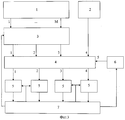
на фиг.3 - структурная схема пеленгатора;figure 3 is a structural diagram of a direction finder;
на фиг.4 - структурная схема приемного устройства;figure 4 is a structural diagram of a receiving device;
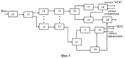
на фиг.5 - структурная схема усилителя преобразователя.figure 5 - structural diagram of the amplifier of the Converter.
Поскольку заявленный способ реализован в работе устройства, то подробное его описание приведено при описании работы пеленгатора.Since the claimed method is implemented in the operation of the device, its detailed description is given when describing the operation of the direction finder.
Пеленгатор (фиг.3) содержит многолучевую пеленгационную антенну 1, ненаправленную антенну 2. Выходы пеленгационной антенны 1 через переключатель 3 и направленный ответвитель 4 подключены к соответствующим входам трех многоканальных приемных устройств 5, выход ненаправленной антенны 2 подключен через направленный ответвитель 4 ко входу 4-го приемного устройства 5, выходы всех приемных устройств 5 подключены к устройству анализа и управления (УАУ) 7, управляющие выходы которого подключены к переключателю 3, всем приемным устройствам 5 и синтезатору рабочих частот 6, выход которого через направленный ответвитель 4 подключен ко входам всех приемных устройств 5.The direction finder (figure 3) contains a multi-beam direction-
Многолучевая пеленгационная антенна 1 состоит из М идентичных антенн, фокальные оси которых сдвинуты друг относительно друга в плоскости пеленгования таким образом, что смежные диаграммы направленности антенн образуют идентичные пеленгационные характеристики. В сумме М антенн перекрывают в плоскости пеленгования всю зону наблюдения 360°. Поскольку ширина парциальной ДН в широком диапазоне частот может изменяться, крутизна пеленгационной характеристики (ПХ) зависит от несущей частоты.A multi-beam direction-
Под крутизной ПХ понимается зависимость соотношения мощностей в пеленгационных каналах от отклонения от равносигнального направления ПХ.Under the slope of the HRP is understood as the dependence of the ratio of power in direction finding channels on the deviation from the equal-signal direction of the HRP.
Пеленгационная антенна 1 может быть выполнена в виде М идентичных рупорных, логопериодических или других типов антенн, обеспечивающих требуемую структуру ДН.
Ненаправленная антенна 2 имеет круговую ДН и может быть выполнена в виде биконической антенны.
Многолучевая пеленгационная антенна 1 и ненаправленная антенна 2 перекрывают весь рабочий диапазон частот.A multi-beam direction-finding
Переключатель 3 содержит М входов по числу выходов многолучевой пеленгационной антенны и три выхода и может быть выполнен на основе 3-х переключателей 4×1, т.е. имеющих 4 входа и один выход. В состав переключателя входит устройство управления, которое обеспечивает отпирание (запирание) соответствующих каналов переключателя 3 по командам от устройства анализа и управления 7. Переключение должно осуществляться таким образом, чтобы всегда ко входам приемных устройств 5 были одновременно подключены три смежных антенны многолучевой пеленгационной антенны 1.
Направленный ответвитель 4 предназначен для подачи сигналов синтезатора рабочих частот 6 на входы всех приемных устройств 5 с целью их калибровки в диапазоне частот. Ослабление направленного ответвителя 4 по направлениям 1-1, 2-2, 3-3, 4-4 минимально с целью не допустить снижения чувствительности пеленгатора. Ослабление сигнала по направлениям 5-1, 5-2 5-3, 5-4 - не менее 20 дБ с целью исключения потерь мощности сигнала ИРИ.The
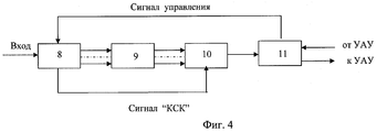
Каждое из приемных устройств 5 представляет собой супергетеродинный двухступенчатый многоканальный приемник. Структурная схема одного приемного устройства 5 приведена на фиг.4.Each of the receiving
В состав одного приемного устройства 5 входит усилитель преобразователь 8, детектор логарифмический многоканальный 9, устройство предварительной обработки 10 и устройство буферное 11.The composition of one
Устройство (УАУ) 7 содержит устройство управления переключателем 3, синтезатором рабочих частот 6 и приемными устройствами 5, а также вычислительное устройство. УАУ 7 - это многопроцессорная вычислительная структура, выполненная на основе сигнальных микропроцессорных устройств и программируемых логических интегральных микросхем (PLIC) (например, типа THS32DVC5402A, ф. Texas Instruments, XC4VLX60FF668 ф.Xilinx, AD9211 ф. Analog Devices).The device (UAU) 7 contains a control device for the
Синтезатор рабочих частот 6 выполнен на основе серийно выпускаемых генераторов, управляемых напряжением (например V585ME06 ф-Z - comm. США, K03-2700-433-R ф.Мет-Circuits, США) и обеспечивает формирование калибровочных СВЧ-сигналов во всем рабочем диапазоне частот и в динамическом диапазоне входных сигналов.The
Пеленгатор работает следующим образом.The direction finder works as follows.
Обзор зоны наблюдения осуществляется за счет электронного переключения выходов многолучевой пеленгационной антенны 1, причем таким образом, что всегда к приемным устройствам 5 одновременно подключены три антенны, имеющие смежные диаграммы направленности.The observation zone is surveyed by electronically switching the outputs of the multi-beam direction-finding
Пеленгатор работает в автоматическом режиме, зона наблюдения задается извне, например с пульта управления станции радиотехнической разведки, куда входит пеленгатор. Если задана зона наблюдения, которая перекрывается одной парциальной диаграммой направленности пеленгационной антенны 1, то переключения не происходит. В этом режиме осуществляется постоянное наблюдение за отдельными источниками излучения. Если зона наблюдения не перекрывается одной парциальной диаграммой направленности пеленгационной антенны 1, то происходит периодическое переключение выходов пеленгационной антенны 1 по изложенному выше алгоритму. Время, в течение которого зона наблюдения не переключается, определяется исходя из необходимости уверенного обнаружения ИРИ и может составлять ориентировочно не более 20 мс.The direction finder operates in automatic mode, the observation zone is set from the outside, for example, from the control panel of the radio intelligence station, where the direction finder is included. If the observation zone is set, which is overlapped by one partial radiation pattern of the direction-finding
Сигнал ИРИ, принятый пеленгационной антенной 1 через переключатель 3 и направленный ответвитель 4, поступает на вход усилителя преобразователя 8 приемного устройства 5.The IRI signal received by the
Сигнал ИРИ, принятый ненаправленной антенной 2, поступает через направленный ответвитель 4 на вход четвертого приемного устройства 5.The IRI signal received by the
Структурная схема усилителя преобразователя приведена на фиг.5.The block diagram of the amplifier of the Converter is shown in Fig.5.
Сигнал, поступивший на усилитель преобразователь 8 усиливается в усилителе 12 и через разветвитель 13 и полосовые фильтры 14, обеспечивающие разделение по частотным поддиапазонам с полосой Δfi, поступает на один из преобразователей 15, где преобразуется в промежуточную частоту fn, далее через делитель мощности 16 поступает одновременно на детекторы 17 и быстродействующий коммутатор 19, продетектированный сигнал поступает на устройство управления 18, которое открывает коммутатор 19 и СВЧ-сигнал через сумматор 20 подается на детектор логарифмический многоканальный 9. Сигналы "КСК" (признак наличия сигнала ИРИ) через устройство управления 18 подаются на УПО 10 для определения несущей частоты источника излучения. Коммутаторы 19 могут управляться также извне от устройства анализа и управления 7 через устройство буферное 11.The signal received by the amplifier, the
Усилитель преобразователь 8 является 1-й ступенью супергетеродинного многоканального приемника. Коммутаторы 19 используются для ограничения полосы разве дуемых частот по командам от УАУ 7. Если коммутатор 19 закрыт командой от УАУ 7, сигнал дальше не проходит, если команда от УАУ 7 на запирание отсутствует, то коммутатор 19 открывается приходящим сигналом. Признак отпирания коммутатора 19 (сигнал "КСК") используется как признак наличия сигнала в данном поддиапазоне частот.The
Детектор логарифмический многоканальный 9 представляет собой вторую ступень супергетеродинного многоканального приемника 5.The multi-channel
В детекторе логарифмическом многоканальном 9 сигнал промежуточной частоты вновь усиливается, диапазон частот Δfi разделяется с помощью полосовых фильтров на одинаковые поддиапазоны Δf2. Далее СВЧ-сигнал детектируется, усиливается логарифмическими видеоусилителями и подается на вход соответствующего канала устройства предварительной обработки 10 (УПО). Количество входов УПО 10 равно количеству выходов детектора логарифмического многоканального 9. В каждом канале УПО 10 с помощью АЦП происходит преобразование видеосигнала в цифровой код и сравнение кодов амплитуд сигналов ИРИ. По номеру канала детектора логарифмического многоканального 9 и признаку о срабатывании коммутатора усилителя преобразователя 8 (сигнал "КСК") определяется значение несущей частоты ИРИ fi.In the detector logarithmic multi-channel 9, the intermediate frequency signal is again amplified, the frequency range Δf i is divided using bandpass filters into the same subbands Δf 2 . Next, the microwave signal is detected, amplified by logarithmic video amplifiers and fed to the input of the corresponding channel of the preliminary processing device 10 (UPR). The number of inputs of the
Информация о коде несущей частоты и амплитуде сигнала поступает через устройство буферное 11 на УАУ 7. В УАУ 7 производится сравнение уровней сигналов ИРИ для значения fi, в том числе и для сигналов, принятых ненаправленной антенной 2, и определяется номер приемного устройства 5 с максимальной амплитудой сигнала. Если сигнал имеет максимальную амплитуду в канале приемного устройства 5, подключенному к центральной из 3-х смежных пеленгационных антенн 1, он принимается к обработке. В противном случае обработка прекращается. Значение пеленга i-го источника радиоизлучения β1 определяется в УАУ 7 моноимпульсным амплитудным методом по формулам:Information about the carrier frequency code and the signal amplitude is received through the
βi=βрсн±Δβi,β i = β pcn ± Δβ i ,
где βрсн (градус) - значение пеленга для равносигнального направления выбранной пеленгационной характеристики, значение (+Δβi) принимают при определении направления по пеленгационной характеристике, образованной центральной и левой смежными антеннами, а (-Δβi) - при определении направления по пеленгационной характеристике, образованной центральной и правой смежными антеннами.where β rsn (degree) is the bearing value for the equal-signal direction of the selected direction-finding characteristic, the value (+ Δβ i ) is taken when determining the direction from the direction-finding characteristic formed by the central and left adjacent antennas, and (-Δβ i ) when determining the direction from the direction-finding characteristic formed by the central and right adjacent antennas.
Δβi, градус=S(fj)·ΔРi,Δβ i , degree = S (f j ) · ΔР i ,
где Δβi - отклонение направления на i-й ИРИ от равносигнального направления выбранной пеленгационной характеристике;where Δβ i is the deviation of the direction on the i-th IRI from the equal-signal direction to the selected direction-finding characteristic;
S(fj), градус/дБ - крутизна пеленгационной характеристики в j-м частотном поддиапазоне.S (f j ), degree / dB is the steepness of the direction-finding characteristic in the j-th frequency subband.
ΔPi, дБ=Рц-Рл(п)±ΔPk(fj,Pi),ΔP i , dB = R c -P l (p) ± ΔP k (f j , P i ),
где Pц, Рл(п), дБ - относительный уровень мощности сигнала в приемном устройстве, подключенном к центральной, левой (или правой) из трех смежных антенн;where P c , R l (p) , dB is the relative signal power level in the receiving device connected to the central, left (or right) of the three adjacent antennas;
ΔPk(fj,Pi) - неидентичность коэффициентов передачи приемных устройств, подключенных к центральной и левой (или правой) из трех смежных антенн в j-м частотном поддиапазоне, при уровне мощности, соответствующей мощности входного сигнала.ΔP k (f j , P i ) - the identity of the transmission coefficients of the receiving devices connected to the central and left (or right) of the three adjacent antennas in the j-th frequency subband, at a power level corresponding to the power of the input signal.
Значение ΔP(fj,Pi) и знак плюс или минус определяют при калибровке по сигналам синтезатора рабочих частот.The value ΔP (f j , P i ) and the plus or minus sign are determined during calibration by the signals of the operating frequency synthesizer.
Таким образом АР определяется с учетом периодической калибровки трактов приемных устройств 5 с помощью сигналов синтезатора частот 6, что позволяет уменьшить погрешность пеленгования, вызванную неидентичностью коэффициента передачи приемных устройств 5 в широком диапазоне частот и при большом динамическом диапазоне входных сигналов. Поправочные коэффициенты для расчета ΔР после проведения калибровки запоминаются в УАУ 7. Калибровка производится в каждом поддиапазоне частот с дискретой канала детектора логарифмического многоканального 10 Δf2. Количество дискрет в динамическом диапазоне определяется характеристиками приемных устройств 5.Thus, the AR is determined taking into account the periodic calibration of the paths of the receiving
Периодичность калибровки выбирается такой, чтобы она не влияла на основную работу пеленгатора, и может составлять десятки минут.The calibration frequency is chosen so that it does not affect the main operation of the direction finder, and can be tens of minutes.
То, что калибровка позволяет уменьшить погрешность определения направления на ИРИ за счет неидентичности коэффициента передачи приемных трактов, подтверждаются следующими выкладками.The fact that the calibration allows to reduce the error in determining the direction to the IRI due to the non-identity of the transmission coefficient of the receiving paths is confirmed by the following calculations.
Допустим, чтоAssume that
f(θ1) и f(θ2) - функции, описывающие парциальные диаграммы направленности пеленгационной антенны;f (θ 1 ) and f (θ 2 ) are functions that describe partial radiation patterns of a direction-finding antenna;
К1, К2 - коэффициенты усиления приемных каналов 1 и 2;To 1 , To 2 - gain of the receiving
Δu - сигнал, несущий информацию об угле прихода.Δu - signal carrying information about the angle of arrival.
Можно показать, что при условии, что К1, К2 - линейные функции, а погрешность логарифмирования незначительнаIt can be shown that, provided that K 1 , K 2 are linear functions, and the logarithm error is negligible
![]()
![]()
Δu'=lgk1-lgk2 - ошибка, обусловленная неидентичностью коэффициентов передачи приемных каналов.Δu '= lgk 1 -lgk 2 - error due to the non-identical transmission coefficients of the receiving channels.
При подаче калибровочного сигналаWhen applying a calibration signal
![]()
![]()
В результате вычитания сигналов 1 и 2 получаемAs a result of subtracting
Δu=lgf(θ1)-lgf(θ2)+lgk1(fc)-lgk2(fc)-lgk2(fk)+lgk2(fk)Δu = logf (θ 1 ) -lgf (θ 2 ) + lgk 1 (f c ) -lgk 2 (f c ) -lgk 2 (f k ) + lgk 2 (f k )
Δu'=lgk1(fc)-lgk1(fk)+lgk2(fc)-lgk2(fk).Δu '= lgk 1 (f c ) -lgk 1 (f k ) + lgk 2 (f c ) -lgk 2 (f k ).
Если k1 и k2 на частотах сигнала fc и калибровки fk отличаются незначительно, то ошибка за счет разноканальности уменьшается.If k 1 and k 2 at the frequencies of the signal f c and calibration f k differ slightly, then the error due to the multi-channel decreases.
Значение пеленга β усредняется за время наблюдения в УАУ 7 и выдается внешнему потребителю.Bearing value β is averaged over the observation time in
Если в зоне наблюдения несколько ИРИ, то пеленги определяются по каждому из них, причем обработка сигналов всех ИРИ проводится параллельно. После обработки всех сигналов происходит переключение и по изложенному выше алгоритму осуществляется обработка сигналов ИРИ в новой пространственной зоне наблюдения.If there are several IRIs in the observation zone, then the bearings are determined for each of them, and the signals of all IRIs are processed in parallel. After processing all the signals, a switching occurs and according to the above algorithm, the processing of IRI signals is carried out in the new spatial observation zone.
Таким образом, если зона наблюдения не перекрывается одной парциальной диаграммой направленности пеленгационной антенны 1, то происходит переключение выходов пеленгационной антенны 1 до тех пор, пока вся зона наблюдения не будет просмотрена, далее цикл повторяется.Thus, if the observation area is not overlapped by one partial radiation pattern of the
Claims (2)
βi=βрсн±Δβi,
где Ррсн (градус) - значение пеленга для равносигнального направления выбранной пеленгационной характеристики, значение (+Δβi) принимают при определении направления по пеленгационной характеристике, образованной центральной и левой смежными антеннами, a (-Δβi) - при определении направления по пеленгационной характеристике, образованной центральной и правой смежными антеннами, Δβi, градус=S(fj)·ΔPi,
где Δβi - отклонение направления на i-й источник радиоизлучения от равносигнального направления выбранной пеленгационной характеристики,
S(fj), градус/дБ - крутизна пеленгационной характеристики в j-м
частотном поддиапазоне,
ΔPi, дБ=Рц-Рл(п)±ΔРk(fj,Pi),
где Рц, Р л(п), дБ - относительный уровень мощности сигнала в приемном устройстве, подключенном к центральной, левой (или правой) из трех смежных антенн,
ΔPk(fj,Pi) - неидентичность коэффициентов передачи приемных устройств, подключенных к центральной и левой (или правой) из трех смежных антенн в j-м частотном поддиапазоне, при уровне мощности, соответствующей мощности входного сигнала, причем значение ΔP((fj,Pi) и знак плюс или минус определяют при калибровке по сигналам синтезатора рабочих частот.1. The method of determining the direction to the source of radio emission, in which the radiated signal is received by a direction-finding antenna, consisting of M identical antennas, the focal axes of which are shifted relative to each other in the direction-finding plane so that adjacent directional patterns of the antennas form identical direction-finding characteristics, and in total M antennas cover the entire 360 ° observation area, characterized in that the received signals are distributed over three identical receiving devices, while the overview of the entire 360 ° observation area carry out electronic switching of the M outputs of the direction-finding antenna to the inputs of three receiving devices, the switching being carried out in such a way that three adjacent antennas are always simultaneously connected to the inputs of the receiving devices at the time of determining the direction to the radio source, and in each receiving device the received signals are distributed over identical frequency subbands , in each of the frequency subbands, the signals are amplified, detected, the detection result is amplified by a logarithmic video amplifier m, the power of the amplified signals is measured taking into account corrections for the non-identity of the transmission coefficients of the receiving devices, which is determined and stored during periodic calibration of the receiving devices according to the frequency synthesizer signals in each frequency subband and in the dynamic range of the input signals, then the frequency subband is determined by the ratio of the measured amplified signal powers in which the signal is received, and for signals having a maximum level in the receiving device connected to the central of three adjacent a antenna, determine the direction of β i to the i-th source of radio emission according to direction-finding characteristics formed by the central and one of the adjacent antennas (right or left), with a high signal level, with a slope value for the j-th frequency subband in which the signal is received, formulas:
β i = β pcn ± Δβ i ,
where P rsn (degree) is the bearing value for the equal-signal direction of the selected direction-finding characteristic, the value (+ Δβ i ) is taken when determining the direction from the direction-finding characteristic formed by the central and left adjacent antennas, and (-Δβ i ) - when determining the direction from the direction-finding characteristic formed by the central and right adjacent antennas, Δβ i , degree = S (f j ) · ΔP i ,
where Δβ i is the deviation of the direction to the i-th source of radio emission from the equal-signal direction of the selected direction-finding characteristic,
S (f j ), degree / dB - steepness of direction-finding characteristic in j-th
frequency sub-band
ΔP i , dB = R c -P l (p) ± ΔP k (f j , P i ),
where R c , R l (p) , dB is the relative power level of the signal in the receiving device connected to the central, left (or right) of the three adjacent antennas,
ΔP k (f j , P i ) is the identity of the transmission coefficients of the receiving devices connected to the central and left (or right) of three adjacent antennas in the jth frequency subband, at a power level corresponding to the power of the input signal, and the value ΔP (( f j , P i ) and the plus or minus sign are determined during calibration using the operating frequency synthesizer signals.
Priority Applications (1)
| Application Number | Priority Date | Filing Date | Title |
|---|---|---|---|
| RU2010144727/09A RU2434240C1 (en) | 2010-11-01 | 2010-11-01 | Radio source and direction finder orientation determining method |
Applications Claiming Priority (1)
| Application Number | Priority Date | Filing Date | Title |
|---|---|---|---|
| RU2010144727/09A RU2434240C1 (en) | 2010-11-01 | 2010-11-01 | Radio source and direction finder orientation determining method |
Publications (1)
| Publication Number | Publication Date |
|---|---|
| RU2434240C1 true RU2434240C1 (en) | 2011-11-20 |
Family
ID=45316763
Family Applications (1)
| Application Number | Title | Priority Date | Filing Date |
|---|---|---|---|
| RU2010144727/09A RU2434240C1 (en) | 2010-11-01 | 2010-11-01 | Radio source and direction finder orientation determining method |
Country Status (1)
| Country | Link |
|---|---|
| RU (1) | RU2434240C1 (en) |
Cited By (9)
| Publication number | Priority date | Publication date | Assignee | Title |
|---|---|---|---|---|
| CN103000996A (en) * | 2012-11-22 | 2013-03-27 | 北京航空航天大学 | Uniform circular array direction-finder antenna receiving mutual impedance test and mutual coupling compensation system |
| RU2505834C1 (en) * | 2012-11-07 | 2014-01-27 | Андрей Владимирович Симонов | Method of detecting radio-frequency radiation in near field of source |
| RU2528177C2 (en) * | 2012-12-28 | 2014-09-10 | Федеральное государственное бюджетное образовательное учреждение высшего профессионального образования "Московский государственный технический университет имени Н.Э. Баумана" (МГТУ им. Н.Э. Баумана) | Method of determining bearing panorama of radio-frequency sources at one frequency |
| RU2530748C2 (en) * | 2012-12-28 | 2014-10-10 | Федеральное государственное бюджетное образовательное учреждение высшего профессионального образования "Московский государственный технический университет имени Н.Э. Баумана" (МГТУ им. Н.Э. Баумана) | Method of determining most probable values of bearings of radio-frequency sources at one frequency |
| RU2551115C1 (en) * | 2013-12-30 | 2015-05-20 | Федеральное государственное бюджетное образовательное учреждение высшего профессионального образования "Московский государственный технический университет имени Н.Э. Баумана" (МГТУ им. Н.Э. Баумана) | Method of characteristics determination of overlapping radiosignals of same frequency |
| RU2593835C2 (en) * | 2014-10-22 | 2016-08-10 | Федеральное государственное казенное военное образовательное учреждение высшего профессионального образования "Военный учебно-научный центр Военно-Морского Флота "Военно-морская академия имени Адмирала Флота Советского Союза Н.Г. Кузнецова" | Method of determining direction of radio-frequency source using method of analysing region relative to axis of symmetry of two horn antennae |
| RU2603356C1 (en) * | 2015-08-31 | 2016-11-27 | Российская Федерация, от имени которой выступает Министерство обороны Российской Федерации | Radio-frequency radiation source direction-finding method |
| RU2765484C2 (en) * | 2021-04-13 | 2022-01-31 | Акционерное общество "Научно-исследовательский институт "Вектор" (АО "НИИ "Вектор") | Method for direction finding and device implementing thereof |
| RU2792039C2 (en) * | 2021-09-13 | 2023-03-16 | Федеральное государственное казенное военное образовательное учреждение высшего образования "Военный учебно-научный центр Военно-воздушных сил "Военно-воздушная академия имени профессора Н.Е. Жуковского и Ю.А. Гагарина" (г. Воронеж) Министерства обороны Российской Федерации | Method for determination of direction to radiation source with phase direction finder on quadcopter |
-
2010
- 2010-11-01 RU RU2010144727/09A patent/RU2434240C1/en not_active IP Right Cessation
Cited By (10)
| Publication number | Priority date | Publication date | Assignee | Title |
|---|---|---|---|---|
| RU2505834C1 (en) * | 2012-11-07 | 2014-01-27 | Андрей Владимирович Симонов | Method of detecting radio-frequency radiation in near field of source |
| CN103000996A (en) * | 2012-11-22 | 2013-03-27 | 北京航空航天大学 | Uniform circular array direction-finder antenna receiving mutual impedance test and mutual coupling compensation system |
| RU2528177C2 (en) * | 2012-12-28 | 2014-09-10 | Федеральное государственное бюджетное образовательное учреждение высшего профессионального образования "Московский государственный технический университет имени Н.Э. Баумана" (МГТУ им. Н.Э. Баумана) | Method of determining bearing panorama of radio-frequency sources at one frequency |
| RU2530748C2 (en) * | 2012-12-28 | 2014-10-10 | Федеральное государственное бюджетное образовательное учреждение высшего профессионального образования "Московский государственный технический университет имени Н.Э. Баумана" (МГТУ им. Н.Э. Баумана) | Method of determining most probable values of bearings of radio-frequency sources at one frequency |
| RU2551115C1 (en) * | 2013-12-30 | 2015-05-20 | Федеральное государственное бюджетное образовательное учреждение высшего профессионального образования "Московский государственный технический университет имени Н.Э. Баумана" (МГТУ им. Н.Э. Баумана) | Method of characteristics determination of overlapping radiosignals of same frequency |
| RU2593835C2 (en) * | 2014-10-22 | 2016-08-10 | Федеральное государственное казенное военное образовательное учреждение высшего профессионального образования "Военный учебно-научный центр Военно-Морского Флота "Военно-морская академия имени Адмирала Флота Советского Союза Н.Г. Кузнецова" | Method of determining direction of radio-frequency source using method of analysing region relative to axis of symmetry of two horn antennae |
| RU2603356C1 (en) * | 2015-08-31 | 2016-11-27 | Российская Федерация, от имени которой выступает Министерство обороны Российской Федерации | Radio-frequency radiation source direction-finding method |
| RU2765484C2 (en) * | 2021-04-13 | 2022-01-31 | Акционерное общество "Научно-исследовательский институт "Вектор" (АО "НИИ "Вектор") | Method for direction finding and device implementing thereof |
| RU2792039C2 (en) * | 2021-09-13 | 2023-03-16 | Федеральное государственное казенное военное образовательное учреждение высшего образования "Военный учебно-научный центр Военно-воздушных сил "Военно-воздушная академия имени профессора Н.Е. Жуковского и Ю.А. Гагарина" (г. Воронеж) Министерства обороны Российской Федерации | Method for determination of direction to radiation source with phase direction finder on quadcopter |
| RU2812273C1 (en) * | 2023-07-11 | 2024-01-29 | Федеральное государственное казенное военное образовательное учреждение высшего образования "Военный учебно-научный центр Военно-воздушных сил "Военно-воздушная академия имени профессора Н.Е. Жуковского и Ю.А. Гагарина" (г. Воронеж) Министерства обороны Российской Федерации | Method for determining direction to radiation source with phase direction finder |
Similar Documents
| Publication | Publication Date | Title |
|---|---|---|
| RU2434240C1 (en) | Radio source and direction finder orientation determining method | |
| US7577464B2 (en) | Compact antenna system for polarization sensitive null steering and direction-finding | |
| US6759983B2 (en) | Method and device for precise geolocation of low-power, broadband, amplitude-modulated signals | |
| Urco et al. | Coherent MIMO to improve aperture synthesis radar imaging of field-aligned irregularities: First results at Jicamarca | |
| RU2390946C2 (en) | Broadband station of radio engineering survey with high sensitivity | |
| RU2285939C1 (en) | Method for controlling airspace, irradiated by external radiation sources, and radiolocation station for realization of said method | |
| Yinusa et al. | Robust satellite navigation by means of a spherical cap conformal antenna array | |
| RU2410712C1 (en) | Method of detecting aerial objects | |
| Anastasio et al. | Optimization of multistatic passive radar geometry based on CRLB with uncertain observations | |
| US3766560A (en) | Radio receiving apparatus for locating a plurality of target transmitters | |
| CA1159934A (en) | Cancellation of group delay error by dual speed of rotation | |
| RU2233456C2 (en) | Object radio detection method | |
| RU2364885C2 (en) | Method for detection and identification of radio transmitter by its radiation in nearest area and device for its realisation | |
| US5812091A (en) | Radio interferometric antenna for angle coding | |
| Shcherbyna et al. | Prospect for using low-element adaptive antenna systems for radio monitoring stations | |
| Memarian et al. | Multiple signals direction finding of IoT devices through improved correlative interferometer using directional elements | |
| RU2332684C1 (en) | Multi-position radio detection method and device for implementing method | |
| Henault et al. | Effects of mutual coupling on the accuracy of adcock direction finding systems | |
| RU2267134C2 (en) | Mode of direction finding of radio signals and a direction finder of radio signals | |
| RU2580933C1 (en) | Method of determining range to radio source | |
| RU2601876C1 (en) | Active jammer direction-finding method | |
| Diao et al. | Compact millimeter wave architecture dedicated to object detection using dual band—dual polarization and impulse method | |
| KR102349841B1 (en) | System and method for detecting jamming singnal direction | |
| RU2717828C1 (en) | Method of determining coordinates of radio-frequency sources and a system for realizing | |
| Antonio et al. | Machine Learning Based Fully Digital UWB Antenna for Direction Finding Systems |
Legal Events
| Date | Code | Title | Description |
|---|---|---|---|
| PC43 | Official registration of the transfer of the exclusive right without contract for inventions |
Effective date: 20120524 |
|
| PC41 | Official registration of the transfer of exclusive right |
Effective date: 20121026 |
|
| MM4A | The patent is invalid due to non-payment of fees |
Effective date: 20151102 |